EP2268552B1 - Becher, herstellungsverfahren und maschine hierfür - Google Patents
Becher, herstellungsverfahren und maschine hierfür Download PDFInfo
- Publication number
- EP2268552B1 EP2268552B1 EP09735305.6A EP09735305A EP2268552B1 EP 2268552 B1 EP2268552 B1 EP 2268552B1 EP 09735305 A EP09735305 A EP 09735305A EP 2268552 B1 EP2268552 B1 EP 2268552B1
- Authority
- EP
- European Patent Office
- Prior art keywords
- cup
- sleeve
- cups
- way
- former
- Prior art date
- Legal status (The legal status is an assumption and is not a legal conclusion. Google has not performed a legal analysis and makes no representation as to the accuracy of the status listed.)
- Not-in-force
Links
- 238000004519 manufacturing process Methods 0.000 title claims description 7
- 238000010227 cup method (microbiological evaluation) Methods 0.000 title 1
- 238000000034 method Methods 0.000 claims description 18
- 239000011796 hollow space material Substances 0.000 claims 1
- 229920006300 shrink film Polymers 0.000 description 18
- 238000000465 moulding Methods 0.000 description 13
- 235000013618 yogurt Nutrition 0.000 description 8
- 238000007373 indentation Methods 0.000 description 6
- 239000000463 material Substances 0.000 description 4
- 238000003856 thermoforming Methods 0.000 description 4
- 239000013013 elastic material Substances 0.000 description 3
- 239000004698 Polyethylene Substances 0.000 description 2
- 239000004743 Polypropylene Substances 0.000 description 2
- 239000004793 Polystyrene Substances 0.000 description 2
- 238000001746 injection moulding Methods 0.000 description 2
- 238000004806 packaging method and process Methods 0.000 description 2
- -1 polyethylene Polymers 0.000 description 2
- 230000008092 positive effect Effects 0.000 description 2
- 239000011324 bead Substances 0.000 description 1
- 238000010297 mechanical methods and process Methods 0.000 description 1
- 230000005226 mechanical processes and functions Effects 0.000 description 1
- 229920000573 polyethylene Polymers 0.000 description 1
- 229920001155 polypropylene Polymers 0.000 description 1
- 229920002223 polystyrene Polymers 0.000 description 1
- 238000003825 pressing Methods 0.000 description 1
- 238000005086 pumping Methods 0.000 description 1
- 230000005855 radiation Effects 0.000 description 1
- 238000011084 recovery Methods 0.000 description 1
- 238000005096 rolling process Methods 0.000 description 1
- 238000000926 separation method Methods 0.000 description 1
- 239000002689 soil Substances 0.000 description 1
- 210000002023 somite Anatomy 0.000 description 1
- 229920001169 thermoplastic Polymers 0.000 description 1
- 239000004416 thermosoftening plastic Substances 0.000 description 1
Images


Classifications
-
- B—PERFORMING OPERATIONS; TRANSPORTING
- B65—CONVEYING; PACKING; STORING; HANDLING THIN OR FILAMENTARY MATERIAL
- B65D—CONTAINERS FOR STORAGE OR TRANSPORT OF ARTICLES OR MATERIALS, e.g. BAGS, BARRELS, BOTTLES, BOXES, CANS, CARTONS, CRATES, DRUMS, JARS, TANKS, HOPPERS, FORWARDING CONTAINERS; ACCESSORIES, CLOSURES, OR FITTINGS THEREFOR; PACKAGING ELEMENTS; PACKAGES
- B65D1/00—Rigid or semi-rigid containers having bodies formed in one piece, e.g. by casting metallic material, by moulding plastics, by blowing vitreous material, by throwing ceramic material, by moulding pulped fibrous material or by deep-drawing operations performed on sheet material
- B65D1/22—Boxes or like containers with side walls of substantial depth for enclosing contents
- B65D1/26—Thin-walled containers, e.g. formed by deep-drawing operations
- B65D1/30—Groups of containers joined together end-to-end or side-by-side
-
- B—PERFORMING OPERATIONS; TRANSPORTING
- B65—CONVEYING; PACKING; STORING; HANDLING THIN OR FILAMENTARY MATERIAL
- B65D—CONTAINERS FOR STORAGE OR TRANSPORT OF ARTICLES OR MATERIALS, e.g. BAGS, BARRELS, BOTTLES, BOXES, CANS, CARTONS, CRATES, DRUMS, JARS, TANKS, HOPPERS, FORWARDING CONTAINERS; ACCESSORIES, CLOSURES, OR FITTINGS THEREFOR; PACKAGING ELEMENTS; PACKAGES
- B65D25/00—Details of other kinds or types of rigid or semi-rigid containers
- B65D25/20—External fittings
- B65D25/24—External fittings for spacing bases of containers from supporting surfaces, e.g. legs
-
- B—PERFORMING OPERATIONS; TRANSPORTING
- B65—CONVEYING; PACKING; STORING; HANDLING THIN OR FILAMENTARY MATERIAL
- B65D—CONTAINERS FOR STORAGE OR TRANSPORT OF ARTICLES OR MATERIALS, e.g. BAGS, BARRELS, BOTTLES, BOXES, CANS, CARTONS, CRATES, DRUMS, JARS, TANKS, HOPPERS, FORWARDING CONTAINERS; ACCESSORIES, CLOSURES, OR FITTINGS THEREFOR; PACKAGING ELEMENTS; PACKAGES
- B65D71/00—Bundles of articles held together by packaging elements for convenience of storage or transport, e.g. portable segregating carrier for plural receptacles such as beer cans or pop bottles; Bales of material
- B65D71/06—Packaging elements holding or encircling completely or almost completely the bundle of articles, e.g. wrappers
- B65D71/08—Wrappers shrunk by heat or under tension, e.g. stretch films or films tensioned by compressed articles
Definitions
- the invention relates to a cup, in particular yogurt cup, with a container element which is at least partially enveloped by a shrink film, in particular a shrink tube.
- yogurt cups in addition to the so-called standard cups, these are simple cups without feet (see EP 0 408 016 A1 . Fig. 1a ), also used cups with foot, especially the so-called foot cup, which have in their lower part a, mostly cylindrical, previewausformung without undercut, and the so-called cup cups, which in its lower part a conical supportiveausformung, which is upwards , tapers to the bottom of the container element, so have a foot shape with undercut.
- thermoplastics such as PE (polyethylene), PP (polypropylene) or PS (polystyrene), with thermoforming or deep-drawing used for the standard cups, while injection molding is used for the cup and cup cups becomes.
- thermoforming is cheaper and faster than injection molding, it is not used for the cup and cup cups. This is due to the shape of the foot cups and cup cups, which is more complicated than the shape of the standard footless cup due to the foot and can not be realized by thermoforming or only with excessive effort.
- the shrink film / shrink tubing protrudes at least in places at the bottom of the container element down and forms or expands the footprint with this projection, the shrink film / shrink tubing in the lower part at least in places from the cup wall and / or the cup bottom protrudes, creating a corresponding cavity.
- the projection formed by the shrink film / shrink tube forms the lower part in particular the foot or the stand element of the cup.
- a manufacturing method is that the container member and the shrink film / shrink tube and at least one molding are guided to each other, and then the shrink film / shrink tubing is shrunk in its outer dimensions and then the molding is separated from the cup. For this purpose, it is advantageous if the molded part is reduced before the separation process.
- a machine for carrying out the process brings together the container element and shrink film / shrink tube and has a molded part which is adapted to shape the shrink film / shrink tube.
- the molded part can be changed in size of its outer dimensions.
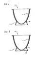
- the cup 10 is after Fig. 1 and 2 a Bembonostiil 11 and the container surrounding a shrink film 13.
- the shrink film (the shrink tube) 13 also referred to as “sleeve” forms even the stationary part of the container (yogurt cup) or expands the footprint, without an additional part (stand element / panel element) is shrunk with.
- the sleeve 13 is closely connected to at least a lower part of the
- the sleeve is in its lower part at least in places from the cup wall and / or the cup base, whereby a corresponding cavity 14 is formed.
- the sleeve 13 has a radial indentation 15 at the lower end, because this results in an increased stability, which carries the weight of the (filled) cup safer, see Figures 2 . 7 . 8th and 11 ,
- the shrinking film 13 is placed around the container element, preferably a heat-shrinkable tube is placed around the container element 11, Figures 3 and 6 ,
- the container element and a further part, which has the desired shape of the base / stand part, hereinafter referred to as "molded part" 27, are brought together in such a way that the desired overall shape of the container results, FIGS. 3, 4 . 6 and 7 .
- the sleeve 13 is brought to shrink. As it cools down, the sleeve solidifies.
- the molded part 27 and the container part 11 are separated from each other, Figures 5 . 7 ,
- the container part 11 and the molded part 27 are guided to each other, and then the sleeve is placed around the two parts.
- the molded part is variable in size, FIGS. 7 to 9 ,
- the molded part 27 may consist entirely or partially of a moldable hollow body which can be changed in size by pumping up and down, in particular pneumatically or hydraulically.
- This hollow body may consist entirely or partially of an elastic material.
- the molding may also be variable in size by a pressing operation by compressing an elastic material wholly or in places, the size of the molding changing as a result of protrusion and retraction of the material.
- the molded part can be changed by a variety of mechanical processes.
- the molded part may consist, in whole or in part, of separate parts, for example, of segments or sectors and may, for example, be disassembled and assembled by sliding operations and thus be variable in size.
- the molding can be variable in size by rolling up and down, for example, a cuff or toroidal ring can be rolled into each other / bent.
- the molding can be completely or partially covered with elastic material to obtain a desired shape.
- the molded part does not have to describe the exact shape of the lower part / base / foot, it is sufficient, depending on the shrinkage behavior of the sleeve / shrink film, that the molded part only describes, for example, a donut-shaped ring or a relatively thin disc.
- the shrink film 13 applies according to such that a voluminous and stable foot shape is achieved.
- a machine which carries out this method, and has corresponding features, namely: the former 27, which is variable in size, and a device that shrinks the sleeve allows.
Landscapes
- Engineering & Computer Science (AREA)
- Mechanical Engineering (AREA)
- Ceramic Engineering (AREA)
- Dairy Products (AREA)
Description
- Die Erfindung betrifft einen Becher insbesondere Joghurtbecher mit einem Behälterelement das von einer Schrumpffolie insbesondere einem Schrumpfschlauch mindestens teilweise umhüllt ist.
- Es ist bekannt, als Joghurtbecher neben den so genannten Standardbechern, das sind einfache Becher ohne Fuß (siehe
EP 0 408 016 A1 ,Fig. 1a ), auch Becher mit Fuß zu verwenden, vor Allem die so genannten Fußbecher, die in ihrem unteren Bereich eine, meist zylindrische, Fußausformung ohne Hinterschneidung aufweisen, und die so genannten Pokalbecher, die in ihrem unteren Bereich eine konische Fußausformung , die sich nach oben, zum Boden des Behälterelementes hin verjüngt, also eine Fußform mit Hinterschneidung aufweisen . Diese bekannten Joghurtbecher werden in einem Stück, meist aus Thermoplasten, wie zum Beispiel PE (Polyethylen), PP (Polypropylen) oder PS (Polystyrol), hergestellt, wobei für die Standardbecher das Thermoformen oder Tiefziehen, für die Fußbecher und Pokalbecher hingegen das Spritzgießen verwendet wird. Obwohl das Thermoformen kostengünstiger und schneller ist als das Spritzgießen, wird es nicht für die Fußbecher und Pokalbecher verwendet. Dies liegt an der Form der Fußbecher und Pokalbecher, die auf Grund des Fußes komplizierter als die Form der fußlosen Standardbecher ist und durch Thermoformen nicht oder nur mit übermäßigem Aufwand realisiert werden kann. - Obwohl sich die Fuß- und Pokalbecher nur wesentlich teurer, aufwendiger und langsamer produzieren lassen als die Standardbecher, welche durch das schnelle und kostengünstige Thermoformen herstellbar sind, werden sie dennoch hergestellt, denn der Fuß, den sie im Unterschied zu den Standardbechern aufweisen,
- erhöht das Außenvolumen der Verpackung, was sich positiv auf die Kaufentscheidung auswirkt;
- kann eine Taillierung bilden, was die Haptik angenehmer macht und den Becher attraktiver erscheinen lässt;
- kann die Becherhöhe vergrößern, was sich positiv auf die Kaufentscheidung auswirkt;
- kann bei einem Becher mit löffelfreundlichem Rundboden dafür sorgen, dass der Becher stabil steht;
- bewirkt, dass keine Bodenvertiefungen im Becherboden nötig sind, um an Höhe zu gewinnen;
- bewirkt, dass sich die Bodenstabilität erhöht, ohne dass Materialsicken nötig sind, welche die Entnahme von Inhalten wie Joghurt mit einem Löffel erschweren.
- Die Fußausformung dieser Fuß- und Pokalbecher bringt also im Vergleich zu den fußlosen Standardbechern sowohl eine praktischere Form wie auch eine hochwertigere Anmutung, was der Grund dafür ist, dass in diese sehr kostspieligen Becherformen investiert wird.
- Es ist Aufgabe der Erfindung, einen Becher, insbesondere Joghurtbecher, zur Verfügung zu stellen, der im Vergleich zu den Standardbechern mindestens die Vorteile des zusätzlichen Volumens und einer möglichen Taillierung aufweist, der vorzugsweise auch stabil stehende Rundbodenformen und eine zusätzliche Becherhöhengewinnung ermöglicht und im Vergleich zu den bekannten Fußbechern und Pokalbechern eine kostengünstigere und/oder schnellere Herstellung ermöglicht. Es ist auch Aufgabe der Erfindung, ein Herstellungsverfahren und eine Herstellungsvorrichtung für einen solchen Becher zur Verfügung zu stellen.
- Diese Aufgabe wird erfindungsgemäß dadurch gelöst, dass die Schrumpffolie/Schrumpfschlauch mindestens stellenweise am unteren Bereich des Behälterelementes nach unten vorsteht und mit diesem Vorsprung die Standfläche bildet oder erweitert, wobei die Schrumpffolie/Schrumpfschlauch im unteren Bereich mindestens stellenweise von der Becherwand und/oder dem Becherboden absteht, wodurch sich ein entsprechender Hohlraum bildet.
- Vorzugsweise wird vorgeschlagen, dass der von der Schrumpffolie/ Schrumpfschlauch gebildete Vorsprung das Unterteil insbesondere den Fuß bzw. das Standelement des Bechers bildet.
- Ein Herstellungsverfahren besteht darin, dass das Behälterelement und die Schrumpffolie/Schrumpfschlauch und mindestens ein Formteil zueinander geführt werden, und danach die Schrumpffolie/der Schrumpfschlauch in seinen Außenabmessungen geschrumpft wird und dann das Formteil vom Becher getrennt wird. Hierzu ist von Vorteil, wenn vor dem Trennvorgang das Formteil verkleinert wird.
- Eine Maschine zum Ausführen des Verfahrens führt das Behälterelement und Schrumpffolie/Schrumpfschlauch zusammen und weist ein Formteil auf, welches dazu geeignet ist, der Schrumpffolie/Schrumpfschlauch die Form zu geben. Hierbei kann das Formteil in der Größe seiner Außenabmessungen veränderbar sein.
- Im Folgenden werden bevorzugte Ausführungsformen der Erfindung beispielhaft anhand der beigefügten Zeichnungen detailliert erläutert.
- Fig. 1
- ist ein Längsschnitt des erfindungsgemäßen Bechers und zeigt eine Becherversion mit Rundboden und einem Fuß (oder Sockel) der sich aus der Schrumpffolie bildet. Die Schrumpffolie weist hierbei keinen radialen Einzug auf.
- Fig. 2
- ist ein Längsschnitt eines vorgeschlagenen Bechers und zeigt eine Becherversion mit Rundboden und einem Fuß (oder Sockel) der sich aus der Schrumpffolie bildet. Die Schrumpffolie weist hierbei einen radialen Einzug auf.
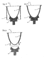
- Fig. 3
- ist ein Längsschnitt des, dem Schrumpfvorgang vorausgehenden Verfahrensschrittes, bei dem das Behälterelement und der Schrumpfschlauch und das Formteil so zueinander geführt wurden, dass der Schrumpfvorgang folgen kann.
- Fig. 4
- ist ein Längsschnitt des Verfahrensschrittes, nachdem der Schrumpfvorgang erfolgt ist. Bei dieser Becherversion weist der Schrumpfschlauch keinen radialen Einzug auf.
- Fig. 5
- ist ein Längsschnitt des Verfahrensschrittes, nachdem das Formteil und der Becher voneinander getrennt wurden.
- Fig. 6
- ist ein Längsschnitt des, dem Schrumpfvorgang vorausgehenden Verfahrensschrittes, bei dem das Behälterelement und der Schrumpfschlauch und das Formteil so zueinander geführt wurden, dass der Schrumpfvorgang folgen kann.
- Fig. 7
- ist ein Längsschnitt des Verfahrensschrittes, nachdem der Schrumpfvorgang erfolgt ist. Bei dieser Becherversion weist der Schrumpfschlauch einen radialen Einzug auf.
- Fig. 8
- ist ein Längsschnitt des Verfahrensschrittes, nachdem das Formteil in seiner Größe mindestens soweit verkleinert wurde, dass es durch die Öffnung des radialen Bodeneinzuges passt und somit das Formteil und der Becher voneinander getrennt werden können.
- Fig. 9
- ist ein Längsschnitt des Verfahrensschrittes, nachdem das Formteil und der Becher voneinander getrennt wurden.
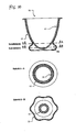
- Fig. 10
- ist ein Längsschnitt eines vorgeschlagenen Bechers und zeigt eine Becherversion mit Rundboden und einem Fuß (oder Sockel) der sich aus der Schrumpffolie bildet, wobei der Fuß nicht als Rotationskörper ausgebildet ist, sondern eine "dreidimensionale" Form aufweist, woraus sich eine erhöhte Stabilität ergeben kann bei weiterhin sehr geringem Materialeinsatz.
- Fig. 11
- ist eine perspektivische Ansicht des Bechers nach
Figur 10 . - Der Becher 10 weist nach
Fig. 1 und 2 ein Behältnisteil 11 und eine das Behältnisteil umgebende Schrumpffolie 13 auf. - Die Schrumpffolie (der Schrumpfschlauch) 13, auch als "Sleeve" bezeichnet, bildet selbst den Standteil des Behältnisses (Joghurtbechers) bzw. erweitert die Standfläche, ohne dass ein Zusatzteil (Standelement/Blendenelement) mit eingeschrumpft wird.
- Der Sleeve 13 verläuft enganliegend um mindestens einen unteren Teil des
- Behälterelementes, und weil kein zusätzliches Stand- bzw. Blendenelement vorhanden ist, steht der Sleeve in seinem unteren Bereich mindestens stellenweise von der Becherwand und/oder dem Becherboden ab, wodurch sich ein entsprechender Hohlraum 14 bildet.
- Vorzugsweise hat der Sleeve 13 einen radialen Einzug 15 am unteren Ende, weil sich hierdurch eine erhöhte Stabilität ergibt, die das Gewicht des (gefüllten) Bechers sicherer trägt, siehe
Figuren 2 ,7 ,8 und11 . - Um diese neue Verpackung herzustellen wird folgendes Verfahren vorgeschlagen, wie in den
Figuren 3 bis 9 dargestellt. - Um das Behälterelement wird die Schrumpffolie 13 gelegt, vorzugsweise wird ein Schrumpfschlauch um das Behälterelement 11 gelegt,
Figuren 3 und6 . - Es werden das Behälterelement und ein weiteres Teil, welches die gewünschte Form des Sockels/Standteiles aufweist, im Folgenden als "Formteil" 27 bezeichnet, so zusammengeführt, dass sich die gewünschte Gesamtform des Behältnisses ergibt,
Figuren 3, 4 ,6 und 7 . Mittels Wärme, insbesondere Wärmestrahlung wird der Sleeve 13 zum Schrumpfen gebracht. Mit seinem Abkühlen erstarrt der Sleeve. Das Formteil 27 und das Behältnisteil 11 werden voneinander getrennt,Figuren 5 ,7 . - Vorzugsweise werden das Behältnisteil 11 und das Formteil 27 zueinander geführt, und danach wird der Sleeve um die beiden Teile gelegt.
- Die Reihenfolge der Verfahrensschritte kann verschieden sein und zwar folgende Schritte nacheinander:
- Unterlegen des Sleeves 13, Zuführen des Formteils 27 in den Sleeve, Schrumpfen des Sleeves
- Zuführen des Formteils, Unterlegen des Sleeves, Schrumpfen des Sleeves.
- Damit sich dieser Vorgang auch bei Sleeveformen mit einem radialen Einzug im unteren Bereich durchführen lässt, ist das Formteil in seiner Größe veränderbar,
Figuren 7 bis 9 . - Es sind verschiedenste Möglichkeiten zur Vergrößerung und Verkleinerung des Formteils und auch Kombinationen hieraus denkbar.
- So kann das Formteil 27 bspw. komplett oder teilweise aus einem formbaren Hohlkörper bestehen, der durch Auf- und Abpumpen, insbesondere pneumatisch oder hydraulisch, in seiner Größe veränderbar ist. Dieser Hohlkörper kann komplett oder teilweise aus einem elastischen Material bestehen.
- Das Formteil kann auch durch einen Pressvorgang in seiner Größe veränderbar sein, indem ein elastisches Material ganz oder stellenweise zusammengedrückt wird, wobei sich die Größe des Formteils durch ein Hervorquillen und Zurückziehen des Materials verändert.
- Das Formteil kann durch eine Vielzahl an mechanischen Vorgängen veränderbar sein. Das Formteil kann ganz oder teilweise aus separaten Teilen bspw. aus Segmenten oder Sektoren bestehen und sich zum Beispiel durch Schiebevorgänge auseinander- und zusammensetzen und so in seiner Größe veränderbar sein.
- Das Formteil kann durch ein Auf- und Abrollen in seiner Größe veränderbar sein, beispielsweise kann ein manschetten- oder torusförmiger Ring ineinander gerollt / gebogen werden.
- Es kann auch bspw. ein ring- oder scheibenförmiges Teil durch einzelne sich drehende Teile gebildet und in der Größe verändert werden, wie es bspw. von einem Zentralverschluss in Fotoapparaten bekannt ist.
- Das Formteil kann ganz oder teilweise mit elastischem Material umhüllt werden, um eine gewünschte Form zu erhalten.
- Das Formteil muss nicht die exakte Form des Unterteils / Sockels / Fußes beschreiben, es reicht aus, je nach Schrumpfverhalten des Sleeves / der Schrumpffolie, dass das Formteil nur bspw. einen torusförmigen Ring oder eine relativ dünne Scheibe beschreibt. Die Schrumpffolie 13 legt sich entsprechend dergestalt an, dass eine voluminöse und stabile Fußform erreicht wird.
- Entsprechend wird eine Maschine vorgeschlagen, die dieses Verfahren ausführt, und entsprechende Merkmale aufweist, nämlich: Den Formgeber 27, der in seiner Größe veränderbar ist, sowie eine Einrichtung, die das Aufschrumpfen des Sleeves ermöglicht.
-
- Joghurtbecher
- Behälterelement
- Standelement, 12' Blendenelement
- Schrumpffolie
- Seitenwand von 11
- Boden von 11
- Seitenwand von 12, 12'
- Vertiefungen an 14, 16
- Erhebungen an 14, 16
- Boden von 12
- Beine von 12
- Verschluss
- Füllung
- Mehrfachjoghurtbecher
- Materialbrücke
- Perforationslinie von 24
- Perforationslinie von 13
- Formteil
Claims (6)
- Becher (10) insbesondere Joghurtbecher mit einem Behälterelement (11) das von einer Schrumpffolie (13) insbesondere einem Schrumpfschlauch mindestens teilweise umhüllt ist, dadurch gekennzeichnet, dass die Schrumpffolie/Schrumpfschlauch (13) mindestens stellenweise am unteren Bereich des Behälterelementes nach unten vorsteht und mit diesem Vorsprung die Standfläche bildet oder erweitert, wobei die Schrumpffolie/Schrumpfschlauch im unteren Bereich mindestens stellenweise von der Becherwand und/oder dem Becherboden absteht, wodurch sich ein entsprechender Hohlraum (14) bildet.
- Becher nach Anspruch 1, dadurch gekennzeichnet, dass der von der Schrumpffolie/Schrumpfschlauch (13) gebildete Vorsprung das Unterteil insbesondere den Fuß bzw. das Standelement des Bechers (10) bildet.
- Herstellungsverfahren für einen Becher nach Anspruch 1 oder 2 mit den Schritten, dass das Behälterelement (11) und die Schrumpffolie/Schrumpfschlauch (13) und mindestens ein Formteil (27) zueinander geführt werden, und danach die Schrumpffolie/der Schrumpfschlauch in seinen Außenabmessungen geschrumpft wird und dann das Formteil vom Becher getrennt wird.
- Verfahren nach Anspruch 3, dadurch gekennzeichnet, dass vor dem Trennvorgang das Formteil (27) verkleinert wird.
- Maschine zum Ausführen des Verfahrens nach einem der Ansprüche 1 bis 4, dadurch gekennzeichnet, dass sie Behälterelement (11) und Schrumpffolie/Schrumpfschlauch (13) zusammenführt und ein Formteil (27) aufweist, welches dazu geeignet ist, der Schrumpffolie/Schrumpfschlauch die Form zu geben.
- Maschine nach Anspruch 5, dadurch gekennzeichnet, dass das Formteil (27) in der Größe seiner Außenabmessungen veränderbar ist.
Applications Claiming Priority (3)
| Application Number | Priority Date | Filing Date | Title |
|---|---|---|---|
| DE102008020284 | 2008-04-22 | ||
| DE102008049248A DE102008049248A1 (de) | 2008-04-22 | 2008-09-26 | Becher und Herstellungsverfahren hierfür |
| PCT/EP2009/002853 WO2009129973A1 (de) | 2008-04-22 | 2009-04-20 | Becher und herstellungsverfahren hierfür |
Publications (2)
| Publication Number | Publication Date |
|---|---|
| EP2268552A1 EP2268552A1 (de) | 2011-01-05 |
| EP2268552B1 true EP2268552B1 (de) | 2013-10-23 |
Family
ID=41111940
Family Applications (1)
| Application Number | Title | Priority Date | Filing Date |
|---|---|---|---|
| EP09735305.6A Not-in-force EP2268552B1 (de) | 2008-04-22 | 2009-04-20 | Becher, herstellungsverfahren und maschine hierfür |
Country Status (3)
| Country | Link |
|---|---|
| EP (1) | EP2268552B1 (de) |
| DE (1) | DE102008049248A1 (de) |
| WO (1) | WO2009129973A1 (de) |
Families Citing this family (3)
| Publication number | Priority date | Publication date | Assignee | Title |
|---|---|---|---|---|
| DE102011010294A1 (de) | 2010-02-26 | 2011-09-01 | Michael Mühlbauer | Becher mit stabilisiertem Sleeve-Fuß |
| FR2976257B1 (fr) * | 2011-06-10 | 2013-06-28 | Decomatic Sa | Procede de protection d'un bord d'un recipient et recipient ainsi equipe |
| CZ25035U1 (cs) * | 2012-11-27 | 2013-03-07 | Zajistovací segment plastového kelímku s prevleceným víckem |
Family Cites Families (13)
| Publication number | Priority date | Publication date | Assignee | Title |
|---|---|---|---|---|
| US2729080A (en) * | 1952-02-07 | 1956-01-03 | Dixie Cup Co | Paper cup holder |
| GB1000169A (en) * | 1963-09-30 | 1965-08-04 | Keyes Fibre Co | Moulded pulp articles such as containers |
| DE1963479A1 (de) * | 1969-12-18 | 1971-06-24 | Reginald Hobbs | Verpackung fuer eine Anzahl von separaten Behaeltern |
| US3854583A (en) * | 1971-12-23 | 1974-12-17 | Owens Illinois Inc | Nestable fabricated thermoplastic container and method of fabrication same |
| DE7535079U (de) * | 1975-11-05 | 1976-03-18 | Suedmilch Ag | Tragegriff fuer Mehrfachpackungen |
| US5018468A (en) * | 1989-04-28 | 1991-05-28 | Peterson Steven R | Multiple position footstrap track for sailboards |
| US5078817A (en) * | 1989-07-12 | 1992-01-07 | Sumitomo Bakelite Company Limited | Process for producing printed container for food packaging |
| US5462180A (en) * | 1994-01-21 | 1995-10-31 | Electra Form, Inc. | Bottle base stand |
| DE29705638U1 (de) * | 1997-04-02 | 1998-08-06 | Fahrion, Otmar, 70806 Kornwestheim | Bechereinheit |
| DE19910675A1 (de) * | 1999-03-11 | 2000-09-14 | Vanessa Klemz | Doppelbecher |
| ITBO20010228A1 (it) * | 2001-04-18 | 2002-10-18 | Sacmi | Apparecchiatura a giostra per la fabbricazione, mediante stampaggio acompressione, di articoli in materiale plastico |
| NL1027179C2 (nl) * | 2004-08-19 | 2006-02-21 | Pharmachemie Bv | Beschermde injectieflacon, en werkwijze voor het vervaardigen daarvan. |
| EP1876107A1 (de) * | 2006-07-03 | 2008-01-09 | Marpe S.r.l. | Glas und Anordnung für eine Zugabe |
-
2008
- 2008-09-26 DE DE102008049248A patent/DE102008049248A1/de not_active Withdrawn
-
2009
- 2009-04-20 WO PCT/EP2009/002853 patent/WO2009129973A1/de not_active Ceased
- 2009-04-20 EP EP09735305.6A patent/EP2268552B1/de not_active Not-in-force
Also Published As
| Publication number | Publication date |
|---|---|
| DE102008049248A1 (de) | 2009-10-29 |
| WO2009129973A1 (de) | 2009-10-29 |
| EP2268552A1 (de) | 2011-01-05 |
Similar Documents
| Publication | Publication Date | Title |
|---|---|---|
| DE2559155C3 (de) | Einweg-Behälter aus in Wärme schrumpffähigem Schaumkunststoff | |
| EP3551422B1 (de) | Verfahren zur herstellung einer schuhsohle | |
| DE1536203B1 (de) | Verfahren und vorrichtung zum herstellen eines behaelters aus einem mit einer endkappe verbunde/ n mantel aus einer kunststoffolie | |
| DE102006025612A1 (de) | Wärmeisolierender Becher | |
| DE202009000245U1 (de) | Verpackungsverbundmaterial | |
| DE2705237C2 (de) | Verpackungsbehälter | |
| EP2268552B1 (de) | Becher, herstellungsverfahren und maschine hierfür | |
| DE2413542A1 (de) | Geschuetzter behaelter und verfahren zu seiner herstellung | |
| DE3735644A1 (de) | Behaelter | |
| DE7713419U1 (de) | Kosmetikstift | |
| DE1704448A1 (de) | Verfahren zur Herstellung von Hohlkoerpern aus Kunststoff-Schaumstoff | |
| EP2511084A1 (de) | Knotenelement aus faserverstärktem Kunststoff sowie Herstellungsverfahren und Verwendung dafür | |
| DE3046977A1 (de) | Kunststoffbehaelter | |
| DE10009303A1 (de) | Einzelaufnahme für ein empfindliches Lager- oder Transportgut und Verfahren zu ihrer Herstellung | |
| DE1938272A1 (de) | Verfahren zur Herstellung von Verpackungen aus Schaumstoffen und nach dem Verfahren hergestellte Verpackungen | |
| DE19703039A1 (de) | Verbesserungen bei der Herstellung von Lenkrädern für Kraftfahrzeuge | |
| DE202004015374U1 (de) | Behälter für Lebensmittel | |
| DE3427732A1 (de) | Laengenveraenderbarer Trinkhalm und Verfahren zu dessen Herstellung | |
| DE3932998C2 (de) | Verpackung | |
| DE2057901A1 (de) | Flaschenkapsel aus Kunststoff-Schrumpffolie sowie Verfahren zu deren Herstellung | |
| DE3032453A1 (de) | Verfahren zur herstellung eines halters fuer desodorierende und desinfizierende mittel fuer toilettenschuesseln und entsprechende vorrichtung | |
| DE2853402A1 (de) | Portionierter hohlstab aus laengsweise gerafftem verpackungsschlauch mit den hohlstab umgebender stuetzhuelle | |
| DE492385C (de) | Hohle, einen menschlichen Fuss und Bein wiedergebende Strumpfform fuer Schaustellungszwecke | |
| DE202015104550U1 (de) | Vorrichtung zur Unterstützung bei der Erzeugung von optischen Mustern | |
| DE7733850U1 (de) | Schale die aus zwei ineinandergreifenden Haelften zu einem geschlossenen Hohlkoerper zusammengesetzt und zur Aufnahme von Formteilen bestimmt ist |
Legal Events
| Date | Code | Title | Description |
|---|---|---|---|
| PUAI | Public reference made under article 153(3) epc to a published international application that has entered the european phase |
Free format text: ORIGINAL CODE: 0009012 |
|
| 17P | Request for examination filed |
Effective date: 20101112 |
|
| AK | Designated contracting states |
Kind code of ref document: A1 Designated state(s): AT BE BG CH CY CZ DE DK EE ES FI FR GB GR HR HU IE IS IT LI LT LU LV MC MK MT NL NO PL PT RO SE SI SK TR |
|
| AX | Request for extension of the european patent |
Extension state: AL BA RS |
|
| 17Q | First examination report despatched |
Effective date: 20110503 |
|
| DAX | Request for extension of the european patent (deleted) | ||
| GRAP | Despatch of communication of intention to grant a patent |
Free format text: ORIGINAL CODE: EPIDOSNIGR1 |
|
| RAP1 | Party data changed (applicant data changed or rights of an application transferred) |
Owner name: MUEHLBAUER, MICHAEL |
|
| GRAP | Despatch of communication of intention to grant a patent |
Free format text: ORIGINAL CODE: EPIDOSNIGR1 |
|
| GRAS | Grant fee paid |
Free format text: ORIGINAL CODE: EPIDOSNIGR3 |
|
| GRAA | (expected) grant |
Free format text: ORIGINAL CODE: 0009210 |
|
| AK | Designated contracting states |
Kind code of ref document: B1 Designated state(s): AT BE BG CH CY CZ DE DK EE ES FI FR GB GR HR HU IE IS IT LI LT LU LV MC MK MT NL NO PL PT RO SE SI SK TR |
|
| REG | Reference to a national code |
Ref country code: GB Ref legal event code: FG4D Free format text: NOT ENGLISH |
|
| REG | Reference to a national code |
Ref country code: CH Ref legal event code: EP |
|
| REG | Reference to a national code |
Ref country code: AT Ref legal event code: REF Ref document number: 637442 Country of ref document: AT Kind code of ref document: T Effective date: 20131115 |
|
| REG | Reference to a national code |
Ref country code: IE Ref legal event code: FG4D Free format text: LANGUAGE OF EP DOCUMENT: GERMAN |
|
| REG | Reference to a national code |
Ref country code: DE Ref legal event code: R096 Ref document number: 502009008223 Country of ref document: DE Effective date: 20131219 |
|
| REG | Reference to a national code |
Ref country code: DE Ref legal event code: R082 Ref document number: 502009008223 Country of ref document: DE Representative=s name: COHAUSZ HANNIG BORKOWSKI WISSGOTT, DE |
|
| REG | Reference to a national code |
Ref country code: NL Ref legal event code: VDEP Effective date: 20131023 |
|
| REG | Reference to a national code |
Ref country code: LT Ref legal event code: MG4D |
|
| PG25 | Lapsed in a contracting state [announced via postgrant information from national office to epo] |
Ref country code: SE Free format text: LAPSE BECAUSE OF FAILURE TO SUBMIT A TRANSLATION OF THE DESCRIPTION OR TO PAY THE FEE WITHIN THE PRESCRIBED TIME-LIMIT Effective date: 20131023 Ref country code: IS Free format text: LAPSE BECAUSE OF FAILURE TO SUBMIT A TRANSLATION OF THE DESCRIPTION OR TO PAY THE FEE WITHIN THE PRESCRIBED TIME-LIMIT Effective date: 20140223 Ref country code: FI Free format text: LAPSE BECAUSE OF FAILURE TO SUBMIT A TRANSLATION OF THE DESCRIPTION OR TO PAY THE FEE WITHIN THE PRESCRIBED TIME-LIMIT Effective date: 20131023 Ref country code: NO Free format text: LAPSE BECAUSE OF FAILURE TO SUBMIT A TRANSLATION OF THE DESCRIPTION OR TO PAY THE FEE WITHIN THE PRESCRIBED TIME-LIMIT Effective date: 20140123 Ref country code: HR Free format text: LAPSE BECAUSE OF FAILURE TO SUBMIT A TRANSLATION OF THE DESCRIPTION OR TO PAY THE FEE WITHIN THE PRESCRIBED TIME-LIMIT Effective date: 20131023 Ref country code: LT Free format text: LAPSE BECAUSE OF FAILURE TO SUBMIT A TRANSLATION OF THE DESCRIPTION OR TO PAY THE FEE WITHIN THE PRESCRIBED TIME-LIMIT Effective date: 20131023 Ref country code: NL Free format text: LAPSE BECAUSE OF FAILURE TO SUBMIT A TRANSLATION OF THE DESCRIPTION OR TO PAY THE FEE WITHIN THE PRESCRIBED TIME-LIMIT Effective date: 20131023 |
|
| PG25 | Lapsed in a contracting state [announced via postgrant information from national office to epo] |
Ref country code: LV Free format text: LAPSE BECAUSE OF FAILURE TO SUBMIT A TRANSLATION OF THE DESCRIPTION OR TO PAY THE FEE WITHIN THE PRESCRIBED TIME-LIMIT Effective date: 20131023 Ref country code: ES Free format text: LAPSE BECAUSE OF FAILURE TO SUBMIT A TRANSLATION OF THE DESCRIPTION OR TO PAY THE FEE WITHIN THE PRESCRIBED TIME-LIMIT Effective date: 20131023 Ref country code: CY Free format text: LAPSE BECAUSE OF FAILURE TO SUBMIT A TRANSLATION OF THE DESCRIPTION OR TO PAY THE FEE WITHIN THE PRESCRIBED TIME-LIMIT Effective date: 20131023 |
|
| PG25 | Lapsed in a contracting state [announced via postgrant information from national office to epo] |
Ref country code: PT Free format text: LAPSE BECAUSE OF FAILURE TO SUBMIT A TRANSLATION OF THE DESCRIPTION OR TO PAY THE FEE WITHIN THE PRESCRIBED TIME-LIMIT Effective date: 20140224 |
|
| REG | Reference to a national code |
Ref country code: DE Ref legal event code: R097 Ref document number: 502009008223 Country of ref document: DE |
|
| PG25 | Lapsed in a contracting state [announced via postgrant information from national office to epo] |
Ref country code: EE Free format text: LAPSE BECAUSE OF FAILURE TO SUBMIT A TRANSLATION OF THE DESCRIPTION OR TO PAY THE FEE WITHIN THE PRESCRIBED TIME-LIMIT Effective date: 20131023 |
|
| PG25 | Lapsed in a contracting state [announced via postgrant information from national office to epo] |
Ref country code: PL Free format text: LAPSE BECAUSE OF FAILURE TO SUBMIT A TRANSLATION OF THE DESCRIPTION OR TO PAY THE FEE WITHIN THE PRESCRIBED TIME-LIMIT Effective date: 20131023 Ref country code: CZ Free format text: LAPSE BECAUSE OF FAILURE TO SUBMIT A TRANSLATION OF THE DESCRIPTION OR TO PAY THE FEE WITHIN THE PRESCRIBED TIME-LIMIT Effective date: 20131023 Ref country code: SK Free format text: LAPSE BECAUSE OF FAILURE TO SUBMIT A TRANSLATION OF THE DESCRIPTION OR TO PAY THE FEE WITHIN THE PRESCRIBED TIME-LIMIT Effective date: 20131023 Ref country code: IT Free format text: LAPSE BECAUSE OF FAILURE TO SUBMIT A TRANSLATION OF THE DESCRIPTION OR TO PAY THE FEE WITHIN THE PRESCRIBED TIME-LIMIT Effective date: 20131023 Ref country code: RO Free format text: LAPSE BECAUSE OF FAILURE TO SUBMIT A TRANSLATION OF THE DESCRIPTION OR TO PAY THE FEE WITHIN THE PRESCRIBED TIME-LIMIT Effective date: 20131023 |
|
| PLBE | No opposition filed within time limit |
Free format text: ORIGINAL CODE: 0009261 |
|
| STAA | Information on the status of an ep patent application or granted ep patent |
Free format text: STATUS: NO OPPOSITION FILED WITHIN TIME LIMIT |
|
| PG25 | Lapsed in a contracting state [announced via postgrant information from national office to epo] |
Ref country code: DK Free format text: LAPSE BECAUSE OF FAILURE TO SUBMIT A TRANSLATION OF THE DESCRIPTION OR TO PAY THE FEE WITHIN THE PRESCRIBED TIME-LIMIT Effective date: 20131023 |
|
| 26N | No opposition filed |
Effective date: 20140724 |
|
| REG | Reference to a national code |
Ref country code: DE Ref legal event code: R119 Ref document number: 502009008223 Country of ref document: DE |
|
| REG | Reference to a national code |
Ref country code: DE Ref legal event code: R097 Ref document number: 502009008223 Country of ref document: DE Effective date: 20140724 |
|
| PG25 | Lapsed in a contracting state [announced via postgrant information from national office to epo] |
Ref country code: MC Free format text: LAPSE BECAUSE OF FAILURE TO SUBMIT A TRANSLATION OF THE DESCRIPTION OR TO PAY THE FEE WITHIN THE PRESCRIBED TIME-LIMIT Effective date: 20131023 Ref country code: LU Free format text: LAPSE BECAUSE OF FAILURE TO SUBMIT A TRANSLATION OF THE DESCRIPTION OR TO PAY THE FEE WITHIN THE PRESCRIBED TIME-LIMIT Effective date: 20140420 |
|
| REG | Reference to a national code |
Ref country code: CH Ref legal event code: PL |
|
| GBPC | Gb: european patent ceased through non-payment of renewal fee |
Effective date: 20140420 |
|
| REG | Reference to a national code |
Ref country code: DE Ref legal event code: R119 Ref document number: 502009008223 Country of ref document: DE Effective date: 20141101 |
|
| REG | Reference to a national code |
Ref country code: FR Ref legal event code: ST Effective date: 20141231 |
|
| REG | Reference to a national code |
Ref country code: IE Ref legal event code: MM4A |
|
| PG25 | Lapsed in a contracting state [announced via postgrant information from national office to epo] |
Ref country code: GB Free format text: LAPSE BECAUSE OF NON-PAYMENT OF DUE FEES Effective date: 20140420 Ref country code: DE Free format text: LAPSE BECAUSE OF NON-PAYMENT OF DUE FEES Effective date: 20141101 Ref country code: CH Free format text: LAPSE BECAUSE OF NON-PAYMENT OF DUE FEES Effective date: 20140430 Ref country code: LI Free format text: LAPSE BECAUSE OF NON-PAYMENT OF DUE FEES Effective date: 20140430 |
|
| PG25 | Lapsed in a contracting state [announced via postgrant information from national office to epo] |
Ref country code: FR Free format text: LAPSE BECAUSE OF NON-PAYMENT OF DUE FEES Effective date: 20140430 Ref country code: SI Free format text: LAPSE BECAUSE OF FAILURE TO SUBMIT A TRANSLATION OF THE DESCRIPTION OR TO PAY THE FEE WITHIN THE PRESCRIBED TIME-LIMIT Effective date: 20131023 |
|
| PG25 | Lapsed in a contracting state [announced via postgrant information from national office to epo] |
Ref country code: IE Free format text: LAPSE BECAUSE OF NON-PAYMENT OF DUE FEES Effective date: 20140420 |
|
| REG | Reference to a national code |
Ref country code: AT Ref legal event code: MM01 Ref document number: 637442 Country of ref document: AT Kind code of ref document: T Effective date: 20140420 |
|
| PG25 | Lapsed in a contracting state [announced via postgrant information from national office to epo] |
Ref country code: AT Free format text: LAPSE BECAUSE OF NON-PAYMENT OF DUE FEES Effective date: 20140420 |
|
| PG25 | Lapsed in a contracting state [announced via postgrant information from national office to epo] |
Ref country code: MT Free format text: LAPSE BECAUSE OF FAILURE TO SUBMIT A TRANSLATION OF THE DESCRIPTION OR TO PAY THE FEE WITHIN THE PRESCRIBED TIME-LIMIT Effective date: 20131023 |
|
| PG25 | Lapsed in a contracting state [announced via postgrant information from national office to epo] |
Ref country code: BG Free format text: LAPSE BECAUSE OF FAILURE TO SUBMIT A TRANSLATION OF THE DESCRIPTION OR TO PAY THE FEE WITHIN THE PRESCRIBED TIME-LIMIT Effective date: 20131023 Ref country code: GR Free format text: LAPSE BECAUSE OF FAILURE TO SUBMIT A TRANSLATION OF THE DESCRIPTION OR TO PAY THE FEE WITHIN THE PRESCRIBED TIME-LIMIT Effective date: 20140124 |
|
| PG25 | Lapsed in a contracting state [announced via postgrant information from national office to epo] |
Ref country code: BE Free format text: LAPSE BECAUSE OF FAILURE TO SUBMIT A TRANSLATION OF THE DESCRIPTION OR TO PAY THE FEE WITHIN THE PRESCRIBED TIME-LIMIT Effective date: 20140430 Ref country code: HU Free format text: LAPSE BECAUSE OF FAILURE TO SUBMIT A TRANSLATION OF THE DESCRIPTION OR TO PAY THE FEE WITHIN THE PRESCRIBED TIME-LIMIT; INVALID AB INITIO Effective date: 20090420 Ref country code: TR Free format text: LAPSE BECAUSE OF FAILURE TO SUBMIT A TRANSLATION OF THE DESCRIPTION OR TO PAY THE FEE WITHIN THE PRESCRIBED TIME-LIMIT Effective date: 20131023 |
|
| PG25 | Lapsed in a contracting state [announced via postgrant information from national office to epo] |
Ref country code: MK Free format text: LAPSE BECAUSE OF FAILURE TO SUBMIT A TRANSLATION OF THE DESCRIPTION OR TO PAY THE FEE WITHIN THE PRESCRIBED TIME-LIMIT Effective date: 20131023 |