EP2263804B1 - Electrostatic atomizer and air conditioner - Google Patents
Electrostatic atomizer and air conditioner Download PDFInfo
- Publication number
- EP2263804B1 EP2263804B1 EP10004941.0A EP10004941A EP2263804B1 EP 2263804 B1 EP2263804 B1 EP 2263804B1 EP 10004941 A EP10004941 A EP 10004941A EP 2263804 B1 EP2263804 B1 EP 2263804B1
- Authority
- EP
- European Patent Office
- Prior art keywords
- unit
- water
- atomizing
- cooling
- electrostatic atomizer
- Prior art date
- Legal status (The legal status is an assumption and is not a legal conclusion. Google has not performed a legal analysis and makes no representation as to the accuracy of the status listed.)
- Not-in-force
Links
Images


Classifications
-
- B—PERFORMING OPERATIONS; TRANSPORTING
- B05—SPRAYING OR ATOMISING IN GENERAL; APPLYING FLUENT MATERIALS TO SURFACES, IN GENERAL
- B05B—SPRAYING APPARATUS; ATOMISING APPARATUS; NOZZLES
- B05B5/00—Electrostatic spraying apparatus; Spraying apparatus with means for charging the spray electrically; Apparatus for spraying liquids or other fluent materials by other electric means
- B05B5/025—Discharge apparatus, e.g. electrostatic spray guns
- B05B5/057—Arrangements for discharging liquids or other fluent material without using a gun or nozzle
-
- B—PERFORMING OPERATIONS; TRANSPORTING
- B05—SPRAYING OR ATOMISING IN GENERAL; APPLYING FLUENT MATERIALS TO SURFACES, IN GENERAL
- B05B—SPRAYING APPARATUS; ATOMISING APPARATUS; NOZZLES
- B05B5/00—Electrostatic spraying apparatus; Spraying apparatus with means for charging the spray electrically; Apparatus for spraying liquids or other fluent materials by other electric means
- B05B5/16—Arrangements for supplying liquids or other fluent material
-
- F—MECHANICAL ENGINEERING; LIGHTING; HEATING; WEAPONS; BLASTING
- F24—HEATING; RANGES; VENTILATING
- F24F—AIR-CONDITIONING; AIR-HUMIDIFICATION; VENTILATION; USE OF AIR CURRENTS FOR SCREENING
- F24F6/00—Air-humidification, e.g. cooling by humidification
- F24F6/12—Air-humidification, e.g. cooling by humidification by forming water dispersions in the air
Definitions
- the present invention relates to an electrostatic atomizer for generating mist of nanometer size (particulate water) by the electrostatic atomization phenomena, and an air conditioner mounting the electrostatic atomizer.
- an electrostatic atomizer in which ceramic porous body delivering water is made to stand up in a water reserving unit, water in the water reserving unit is sucked up to the upper end by capillary action, and by applying high voltage to the ceramic porous body, at the upper end which is pin-shaped, sucked water is crushed and released in the air. It has been necessary for the user to supply water to the water reserving unit (for example, refer to Patent Document 1).
- Patent Document 2 Another electrostatic atomizer has been proposed as well as Patent Document 2, in which a cooling surface (a heat exchanging surface) is included as the water supply means, a water keeping unit is provided for keeping condensed water which is condensed and generated on the cooling surface, the ceramic porous body is contacted with the water keeping unit, and the water in the water keeping unit is delivered to the ceramic porous body by capillary action up to the top end and atomized (for example, refer to Patent Documents 3 to 5).
- a cooling surface a heat exchanging surface
- a water keeping unit is provided for keeping condensed water which is condensed and generated on the cooling surface
- the ceramic porous body is contacted with the water keeping unit
- the water in the water keeping unit is delivered to the ceramic porous body by capillary action up to the top end and atomized
- the metal bar does not have a slit hole like the ceramic porous body, it has no water absorption function nor delivery function. Accordingly, there is a problem that only small amount of the atomization (generating mist amount) can be obtained using only attached amount of water condensed on the surface of the top end of the metal bar, and further the mist generation is not stable.
- JP 2009 090282 A discloses an electrostatic atomizer comprising water supply means having a Peltier unit and a cooling unit contacting to a cooling surface of the Peltier unit, for dropping water condensed at the cooling unit from the cooling unit in a direction of gravitation force; and an atomizing electrode formed by a porous body for receiving the water dropped from the water supply means and for atomizing the water at a top end atomizing unit by being applied with high voltage.
- the present invention is done in order to solve the above problems, and aims to provide an electrostatic atomizer which can guide rapidly and steadily water supplied from the water supply means to the top end atomizing unit of the atomizing electrode and can obtain stably a large amount of electrostatic mist, and an air conditioner which can stably release plenty of the electrostatic mist to the indoors using the electrostatic atomizer.
- an electrostatic atomizer includes the features of claim 1.
- Figs. 1 to 17 show the first embodiment; first, with reference to Figs. 1 to 4 , a configuration of an electrostatic atomizer 100 will be explained.
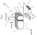
- the electrostatic atomizer 100 of the present embodiment includes an atomizing electrode 2 and a counter electrode 3 to generate an electrostatic mist 1 of nanometer (10 -9 m) size as shown in Fig. 1 .
- the atomizing electrode 2 includes a trunk unit 28 and a top end atomizing unit 29 which are both plate-shaped, and water supplied to the trunk unit 28 is moved (delivered) to the top end atomizing unit 29.
- the top end (the projected end) of the top end atomizing unit 29 is arranged so as to be directed to the counter electrode 3.
- porous body is used as material; however, here, in particular, foam metal which is metal porous body having three-dimensional net structure is used. These will be explained later in detail.
- the counter electrode 3 works as a ground electrode, which is potential 0 V, and negative DC voltage of -4 to -6 V is applied to the atomizing electrode 2.
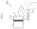
- the shape of the trunk unit 28 of the atomizing electrode 2 is almost rectangular-shaped, and above the trunk unit 28, separated with a space of a predetermined distance L1 (refer to Fig. 2 ), plural cooling fins 8b of the cooling unit 8, which is contacted to the cooling surface of the Peltier unit 6 being a part of the water supply means, are positioned so that the fins are parallely aligned in almost horizontal direction.
- the trunk unit 28 is formed by extending the long-side direction width (the width of the longitudinal direction) in the parallel-aligning direction of the cooling fins 8b. Namely, the long-side direction (the longitudinal direction) of the trunk unit 28 being almost rectangular-shaped almost agrees with the parallel-aligning direction of the cooling fins 8b of the cooling unit 8.
- the atomizing electrode 2 is positioned below the cooling fins 8b with the space of the predetermined distance L1 and includes the trunk unit 28 being tabular-shaped which extends the width of the longitudinal direction (the long-side direction) in the parallel-aligning direction of the cooling fins 8b. Then, the short-side direction of the trunk unit 28 almost agrees with the projected direction of the cooling fins 8b.
- the trunk unit 28 has an elongated shape, in which the width of the long-side direction is equal to or greater than three times of the width of the short-side direction. Then, the plate thickness of the plate-shaped atomizing electrode 2 is smaller than the short-side direction width of the trunk unit 28.
- the shape of the trunk unit 28 has been explained as almost rectangular-shaped, the shape is not limited to a complete rectangle which forms a right angle with the long side and the short side but can be a parallelogram or a trapezoid in which the angle formed by the short side with respect to the long side is an acute angle or an obtuse angle, namely, the two long sides are mutually in parallel, but the short side is not connected orthogonally to the long side.
- the trunk unit 28 being almost rectangular-shaped includes not only a rectangle, but also a parallelogram or a trapezoid like the above.
- the atomizing electrode 2 is provided with the top end atomizing unit 29 in the middle of the side surface of the long-side direction (the longitudinal direction) of the trunk unit 28 so as to be projected from the side surface as shown in Fig. 1 .
- the top end atomizing unit 29 is a plate-shaped projection having the same thickness and being continuous to the trunk unit 28, the shape of which is triangular-shaped in a top plan view.
- the surface of the bottom side is connected to the side surface in the long-side direction of the trunk unit 28, a top end 29a (the projected end) being a peak is directed to the counter electrode 3.
- This top end 29a becomes a part discharging with the counter electrode 3.
- Figs. 1 to 4 show a case where the projection which is the top end atomizing unit 29 is one; however, the projection can be plural.
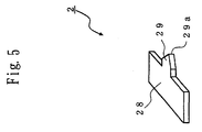
- the shape of projection which is the top end atomizing unit 29 can be, what is called, a home-plate shape having a rectangular-shaped part which is connected to the trunk unit 28 and a triangular-shaped part of which the surface of the bottom side is connected to the rectangular-shaped part as shown in Fig. 5 , and the top end 29a (the projected end) being a peak of the triangular-shaped part can be directed to the counter electrode 3.
- the top end atomizing unit 29 of the atomizing electrode 2, whether it is triangular-shaped as shown in Fig. 1 or home-plate-shaped shown in Fig. 5 in top plan view, as well as the trunk unit 28, is plate-shaped having a thickness and formed in a united manner with the trunk unit 28, the top end 29a directed to the counter electrode 3 also has a thickness, and the top end 29a is pointed linearly. Since the top end 29a is pointed linearly, two angular parts are formed at the upper and lower ends.
- the top end atomizing unit 29 is formed continuously to the trunk unit 28 in the middle of the side surface extending to the parallel-aligning direction of the cooling fins 8b which is the long-side direction (the longitudinal direction) of the trunk unit 28 being tabular-shaped, and is a plate-shaped projection projected towards the counter electrode 3 from the side surface in the long-side direction of the trunk unit 28; the shape is such that the projection width decreases as approaching to the top end 29a and that the top end 29a is formed to be a linearly fine state or a very thin state being close to the linearly fine state.
- the counter electrode 3 is formed to be plate-shaped using conductive metal or resin, and has an opening in its almost center.
- the counter electrode 3 is positioned separately with a certain distance from the top end 29a of the top end atomizing unit 29 so that the opening should face the top end atomizing unit 29 of the atomizing electrode 2.
- the electrostatic atomizer 100 shown in Fig. 1 has the water supply means structured by a Peltier unit 6, a heat radiating part 7 contacting to a heat radiating surface of the Peltier unit 6, and a cooling unit 8 contacting to a cooling surface positioned at the opposite side of the heat radiating surface. Then, w ater generated by the water supply means is supplied by dropping with the gravitational force to a top surface of the trunk unit 28 of the atomizing electrode 2.
- Each of the heat radiating part 7 and the cooling unit 8 has a base board contacting to the Peltier unit 6 and plural fins standing almost vertically on the surface at the non-Peltier unit side of the base board.
- the plural fins of the heat radiating part 7 and the cooling unit 8 are aligned in a direction being almost orthogonal to the passing airflow so that each fin should be in almost parallel with the passing airflow.
- respective fins of the heat radiating part 7 and the cooling unit 8 are aligned in almost horizontal direction which is a direction being almost orthogonal to the direction of gravitational force.
- the fins of the heat radiating part 7 are formed to have a surface area being larger than the fins of the cooling unit 8.
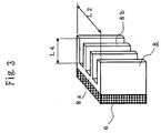
- Fig. 3 is a schematic configuration diagram of the cooling unit 8; the cooling unit 8 includes the base board 8a contacting to the Peltier unit 6 and the plural cooling fins 8b standing almost vertically on the surface of the base board 8a at non-Peltier unit side.
- the plural cooling fins 8b are aligned in the almost horizontal direction as discussed above.
- L2 shown in Fig. 3 is the width of the cooling fins 8b in the parallel-aligning direction, and is a distance from the outer side surface of the cooling fin 8b located at one end of the parallel-aligning direction to the outer side surface of another cooling fin 8b located at the other end. Including the cooling fins 8b at both ends, the plural cooling fins 8b located within a range of the width L2 are all exposed in the air.
- L4 shown in Fig. 3 is a projected height of the cooling fin 8b and is a distance to the projected end from the base end on the base board 8a, namely, a distance to the projected end of the cooling fin 8b from the surface at the non-Peltier unit side of the base board 8a.
- the lower end surfaces of the plural cooling fins 8b are totally exposed so as to face the top surface of the trunk unit 28 of the atomizing electrode 2 with the predetermined distance L1.
- the distance L4 should be changed to another value obtained by subtracting the covered distance. In such a case, the distance L4 becomes the exposed length of the lower end surface of the cooling fins 8b in the projected direction.
- Plural semiconductor PN junctions are provided inside of the Peltier unit 6; when DC voltage of around 1 to 5 V is applied to the Peltier unit 6 from the low voltage supplying unit 5, the current flows in one direction. The heat amount of the heat discharging surface is increased by the Peltier effect, and the heat is absorbed at the cooling surface. By this operation, the heat radiating part 7 is heated, and the cooling unit 8 is cooled. When the temperature of the cooling unit 8 is cooled up to equal to or less than the dew point of the passing air by the Peltier unit 6, condensation water 10 which is condensed water in the air is generated on the surface of the cooling fins 8b of the cooling unit 8.
- the generated condensation water 10 falls along the surface of the cooling fins 8b towards the lower ends of the cooling fins 8b by the gravitational force, and after it falls up to the lower ends, the condensation water is dropped downwardly from the cooling fins 8b by the gravitational force. Since the passing air flows in almost same direction of the gravitational force, the condensation water 10 is easily generated on the surface of the upper side of the cooling fins 8b. As the passing air flows downwardly, the water in the air decreases, and thus the condensation becomes difficult. The condensation hardly occurs on the lower end surfaces of the cooling fins 8b.
- the heat radiating part 7 and the cooling unit 8 are formed by aluminum as material.
- a general contact angle with water of aluminum fin is 50 to 70 degrees.
- at least water repellent treatment for increasing the contact angle up to equal to or greater than 90 degrees or hydrophilic treatment for decreasing the contact angle up to equal to or less than 30 degrees is carried out on the cooling fins 8b.
- the contact angle of water means an angle made by the waterdrop surface and the solid surface when the waterdrop is put on the solid surface and the waterdrop is balanced, that is, an angle made by a tangential line formed by the waterdrop and the surface of the cooling fin 8b at a contacting point where the waterdrop contacts the surface of the cooling fin 8b.
- the atomizing electrode 2 is arranged through the space of predetermined length of L1 from the lower end of the cooling fin 8b as shown in Fig. 2 .
- the cooling unit 8 and the atomizing electrode 2 do not have parts which directly contact with each other.
- the condensation water 10 dropped from the lower end of the cooling fin 8b falls to the top surface of the trunk unit 28 of the atomizing electrode 2.
- the trunk unit 28 being almost rectangular-shaped of the atomizing electrode 2 extends the long-side direction in parallel-aligning direction of the cooling fins 8b and is arranged directly below (just below) the cooling fins 8b with the space of the distance L1.
- the condensation water 10 fallen by the gravitational force on the top surface of the trunk unit 28 is absorbed to the inside of the atomizing electrode 2 which is the metal porous body and is moved by the surface diffusion in gaps, the inside of which are mutually connected three-dimensionally with each other. Th e condensation water 10 is delivered to the top end atomizing unit 29 from the trunk unit 28 in the inside of the atomizing electrode 2 by surface diffusion phenomena like this.
- the water (the condensation water 10) is delivered up to adjacent area of the top end 29a of the top end atomizing unit 29 of the atomizing electrode 2, the water adjacent to the top end 29a is applied with the high voltage, and the water is charged with the same potential as the atomizing electrode 2, namely, the negative high voltage, since the negative high voltage of -4 to -6 kV is applied to the atomizing electrode 2 with respect to the counter electrode 3 which is the ground electrode. Therefore, the charged water is pulled to the outside of the atomizing electrode 2 locally from the top end 29a and forms an embossment of a so-called Taylor cone by the action of coulomb force in the electrostatic field.
- the top end atomizing unit 29 is formed to be plate-shaped and the top end 29a which is the discharging part is pointed linearly, it is possible to converge the electric fields at least at two angular parts of the upper and lower ends of the top end 29a.
- the top end which is the discharging part is sharpened to be pin-shaped, and Taylor cone of water is formed at only the pin-shaped top end, in case of the sharpened linearly top end 29a, Taylor cone of water can be formed at least at two angular parts of the upper and lower ends.
- the discharging part is formed to be the pin-shaped top end, it is possible to efficiently generate a large amount of the electrostatic mist 1.
- top end 29a is sharpened linearly, electric field is converged, though it does not as much as the angular parts of the upper and lower ends, Taylor cone of water is sometimes formed at somewhere between the upper and lower angular parts, and it is possible to efficiently generate a large amount of the electrostatic mist 1.
- an angle ⁇ (shown in Fig. 4 ) of the peak of a triangular shape in a top plan view towards the counter electrode 3 should be an acute angle, preferably equal to or less than 60 degrees.
- the electrostatic mist 1 generated like this is called as simply mist or particulate water; since it is charged, the electrostatic mist 1 is sometimes called as charged mist or charged particulate water. Further, since the size is nanometer size, the electrostatic mist 1 is sometimes also called as nano mist. In either way, the electrostatic mist 1 is charged mist of nanometer size (particulate water) generated from water applied with high voltage and miniaturized by Rayleigh fission; here, the mist generated like this is called as the electrostatic mist 1. Further, to generate the electrostatic mist 1 like this is called as electrostatic atomization, and the atomization means to atomize water. Then, atomizing amount means generation amount (production amount) of the electrostatic mist 1.
- Fig. 4 is a schematic configuration diagram of the atomizing electrode 2.
- L3 shown in this figure is a width of the long-side direction (the longitudinal direction) of the top surface of the trunk unit 28 exposed facing the cooling fins 8b located above, and a width in the same direction as the parallel-aligning direction of the cooling fins 8b.
- the one end part is not included in the above the width L3.
- the width L3 does not simply mean the length of the long-side direction of the trunk unit 28, but is the width of the long-side direction of the top surface of the trunk unit 28 exposed to the cooling fins 8b located above, and the part which is not exposed to the upper side is not included in the width L3.
- L5 shown in Fig. 5 is a width of the direction being orthogonal to L3, a width of the short-side direction of the top surface of the trunk unit 28 exposed to the cooling fins 8b, and a width in the same direction as the projected direction of the cooling fins 8b.
- the atomizing electrode 2 is formed so that the width L3 of the trunk unit 28 should be equal to or greater than the width L2 of the above-discussed parallel-aligning direction of the cooling fins 8b. Namely, the width L3 ⁇ the width L2. Further, the atomizing electrode 2 is formed so that the width L5 of the trunk unit 28 should be equal to or greater than the above-discussed projected height L4 of the cooling fins 8b. Namely, the width L5 ⁇ L4.
- the trunk unit 28 of the atomizing electrode 2 is arranged with respect to the cooling fins 8b so that when the cooling fins 8b are totally projected over the trunk unit 28 of the atomizing electrode 2 in the direction of gravitational force, the parallel-aligning direction width L2 should almost agree with the long-side direction width L3 of the trunk unit 28, or the width L2 should be included in the width L3, and further, the height L4 should almost agree with the short-side direction width L5 of the trunk unit 28, or the height L4 should be included in the width L5.
- the plural cooling fins 8b located above and the trunk unit 28 of the atomizing electrode 2 which is located below the plural cooling fins 8b and positioned with the gap L1 so as not to contact the cooling unit 8 have such a positional relation. Therefore, it is possible to receive laconically and steadily a large amount of the condensation water 10 dropped widely from the lower ends of the plural cooling fins 8b in the parallel-aligning direction by the gravitational force using the top surface of the trunk unit 28 acting as the water receiving surface and deliver the condensation water 10 to the top end atomizing unit 29, and thus a large amount of the electrostatic mist 1 can be generated stably.
- the condensation water 10 is dropped from any position in the projected direction having a range of the height L4 of the lower ends of the cooling fins 8b, it is possible to receive laconically and steadily the condensation water 10 by the top surface of the trunk unit 28 acting as the water receiving surface, and thus a large amount of the electrostatic mist 1 can be generated stably.
- the cooling fins 8b are aligned in parallel in the horizontal direction which is almost orthogonal to the airflow, the trunk unit 28 of the atomizing electrode 2 is made tabular-shaped and is formed so as to extend the width of the long-side direction in the parallel-aligning direction. Consequently, the condensation water 10 which is efficiently condensed with a large amount by the cooling fins 8b can be received by the top surface of the trunk unit 28 laconically and steadily, and thus the generation of the electrostatic mist 1 is stably continued.
- the cooling unit 8 of the water supply means does not always need to include the cooling fins 8b, but the cooling unit 8 can be configured so that only the base board 8a being tabular-shaped should contact the cooling surface of the Peltier unit 6, though the amount of generated condensation water 10 is reduced compared with a case having the cooling fins 8b.
- the base board 8a acts as the cooling board
- the condensation water 10 is generated on the surface of the opposite side of the surface contacting the Peltier unit 6 (when the cooling fins 8b are provided, the surface from which the plural cooling fins 8b are projected), the condensation water 10 falls along the surface by the gravitational force towards the lower end, and after it falls up to the lower end, the condensation water 10 is dropped downwardly from the base board 8a by the gravitational force.
- the width L3 of the trunk unit 28 of the atomizing electrode 2 can be formed so as to be equal to or greater than the width (the length) of the base board 8a in the horizontal direction. Namely, the width L3 ⁇ the width of the base board 8a in the horizontal direction.
- the trunk unit 28 of the atomizing electrode 2 is arranged with respect to the cooling unit 8 so that the width of the base board 8a in the horizontal direction should almost agree with the long-side direction width L3 of the trunk unit 28, or should be included in the width L3 when the base board 8a is projected over the trunk unit 28 of the atomizing electrode 2 in the direction of gravitational force.
- the trunk unit 28 is positioned with the gap of the distance L1 below the base board 8a, and the cooling unit 8 and the atomizing electrode 2 are not contacted.
- the positional relation is made like the above, and thereby it is possible to receive laconically and steadily the condensation water 10 dropped widely in the horizontal direction from the lower end of the base board 8a which is the cooling board by the gravitational force using the top surface of the trunk unit 28 acting as the water receiving surface and deliver the water to the top end atomizing unit 29; and thus a large amount of the electrostatic mist 1 can be generated stably.
- the width L3 of the trunk unit 28 of the atomizing electrode 2 is made equal to or greater than the horizontal direction width of the cooling unit 8, namely, the width L3 is set to be the width L3 ⁇ the horizontal direction width of the cooling unit 8, and further, when the cooling unit 8 is projected over the trunk unit 28 of the atomizing electrode 2 in the direction of gravitational force, the horizontal direction width of the cooling unit 8 is made to almost agree with the long-side direction width L3 of the trunk unit 28, or to be included in the width L3, and thereby it is possible to receive laconically and steadily the condensation water 10 dropped widely from the cooling unit 8 in the horizontal direction by the gravitational force by the top surface of the trunk unit 28 acting as the water receiving surface and deliver the water to the top end atomizing unit 29; and thus a large amount of the electrostatic mist 1 can be generated stably.
- the cooling fins 8b are provided projectedly also from the left and right ends of the base board 8a, and the width L2 in the parallel-aligning direction corresponds to the horizontal direction width of the cooling unit 8.
- the base board 8a is generally formed to be rectangular-shaped and is arranged so that the longitudinal direction should be orthogonal to the direction of passing airflow. Since the generation of condensation water 10 in the cooling unit 8 mostly occurs in the upstream of the cooling unit 8 (of the passing airflow), such arrangement allows to have a large area of the base board 8a (the surface of the opposite side of the surface contacting to the Peltier unit 6) contacting the airflow which contains a large amount of water. Therefore, the condensation water 10 generated in the cooling unit 8 is to be dropped widely in the horizontal direction.
- the condensation water 10 received by the trunk unit 28 can be delivered rapidly to the top end atomizing unit 29 compared with the case where the top end atomizing unit 29 is provided in the short-side direction side surface. Therefore, together with the fact that the passage of the condensation water 10 to the atomizing electrode 2 is a direct drop to the trunk unit 28 by the gravitational force, it is possible to generate the electrostatic mist 1 in a short time from starting the operation of the electrostatic atomizer 100.
- the top end atomizing unit 29 should be arranged in the long-side direction side surface of the trunk unit 28 and at a position corresponding to the center of the parallel-aligning direction width L2 of the cooling fins 8b.
- the atomizing electrode 2 is configured not to reserve the condensation water 10 supplied by dropping from the cooling unit 8 in its surroundings.
- the holding frame for fixing the atomizing electrode 2 is not made to be a container so as not to reserve water.
- an opening which opens downwardly is provided at the surrounding part including the lower surface (the surface of the opposite side of the top surface facing the cooling unit 8) of the atomizing electrode 2, so that unnecessary water is discharged from the holding frame of the atomizing electrode 2 through the opening; and thus water is made not to be reserved around the atomizing electrode 2.
- the counter electrode 3 is provided so as to keep the potential difference constant with the atomizing electrode 2; however, without providing the counter electrode 3, the electrostatic mist 1 can be generated by discharge in the air (discharge with floating potential in the air). Further, by using a member of which potential is around 0 V among the equipment mounting the electrostatic atomizer 100 (for example, if it is mounted on the indoor unit of the air conditioner, the indoor heat exchanger provided inside of the indoor unit) as a substitute of the counter electrode 3 to keep the potential difference with the atomizing electrode 2 and the electrostatic mist 1 can be generated.
- the passing air amount (the amount of the passing airflow) to the cooling unit 8 is made small compared with the heat radiating part 7.
- the heat radiating part 7 makes the upstream side open and does not give the ventilation resistance to the airflow passing the heat radiating part 7; however, at the cooling unit 8 side, a fence or a rib, etc. is provided at the upstream side to restrict the opening of the inflow opening to decrease the passing air amount.
- the passing air amount is decreased, the flow speed of the airflow passing the cooling unit 8 is made small up to around 0.1 m/s which is slight breeze status, and thereby the outflow of the airflow with seizing the cooling heat can be avoided. As a result of this, the cooling fins 8b can be cooled efficiently.
- the atomizing electrode 2 Since the atomizing electrode 2 is formed by the metal porous body, the atomizing electrode 2 has property to deliver the received water to the top end atomizing unit 29 by receiving the condensation water 10 dropped on anywhere of the top surface of the trunk unit 28.
- the atomizing electrode 2 itself includes three functions: such as the water receiving unit, the water delivering means, and the atomizing unit (the generating part of the electrostatic mist 1). Therefore, it is possible to have an effect to collect water rapidly to the top end atomizing unit 29 and to carry out the electrostatic atomization efficiently, properly, and stably.
- the trunk unit 28 of the atomizing electrode 2 is provided below the cooling unit 8 contacting the cooling surface of the Peltier unit 6 in the direction of gravitational force with the gap of the predetermined distance L1 at a distant position from which the direct contact with the cooling unit 8 is impossible.
- the predetermined gap L1 needs to have a distance such that the atomizing electrode 2 and the cooling unit 8 should not be electrically connected.
- the top surface of the trunk unit 28 exposed to the cooling fins 8b is formed flatly without providing a projection such as the top end atomizing unit 29 to which electric fields are converged.
- the distance L1 needs to be at least 3 mm.
- the condensation water 10 is made to be dropped from the cooling fins 8b to the trunk unit 28, so that the insulating distance between the cooling fins 8b and the trunk unit 28 is essentially shortened by the length of the waterdrop just before dropping from the lower ends of the cooling fins 8b; considering such amount, the distance L1 needs to be at least 5 mm, and it is better to provide the trunk unit 28 with the gap L1 of equal to or greater than 5 mm from the lower ends of the cooling fins 8b.
- the condensation water 10 is dropped directly to the top surface of the trunk unit 28 by the gravitational force. There is no element to prevent the movement of water from the cooling unit 8 to the trunk unit 28. By this operation, it is possible to supply the condensation water 10 generated in the cooling unit 8 rapidly and steadily to the atomizing electrode 2 in a short time.
- the metal porous body (a detail will be explained later) is used as material of the atomizing electrode 2, and thereby once water is supplied to a part of the trunk unit 28, the water proceeds through the inside voids by the surface diffusion and can be delivered rapidly to the top end atomizing unit 29; thus it is possible to reduce the time from starting the operation until the generation of the electrostatic mist 1.
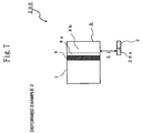
- Fig. 6 shows an electrostatic atomizer 150 of a deformed example 1.
- the top end atomizing unit 29 of the atomizing electrode 2 is projected on the long-side direction side surface of the trunk unit 28 in the same direction as the projected direction of the cooling fins 8b; however, in the electrostatic atomizer 150, the top end atomizing unit 29 of the atomizing electrode 2 is projected on the long-side direction side surface at the opposite side of that surface, so as to be projected in the direction being opposite to the projected direction of the cooling fins 8b, namely, the projected direction of the fins of the heat radiating part 7.
- the counter electrode 3 is provided at the side of the heat radiating part 7 so as to face the top end atomizing unit 29 at that time.
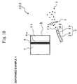
- the electrostatic atomizer 200 of a deformed example 2 will be explained.
- the top end atomizing unit 29 is provided at the end part (on the short-side direction side surface) of the trunk unit 28, that is, the position of the top end atomizing unit 29 with respect to the trunk unit 28 is not like the electrostatic atomizer 100 shown in Fig. 1 in which the projection position of the top end atomizing unit 29 is on the long-side direction side surface of the trunk unit 28.
- the trunk unit 28 is arranged by extending the long-side direction in the direction which agrees with the parallel-aligning direction of the plural cooling fins 8b from which the condensation water 10 is dropped.
- Fig. 8 is a top plan view of the atomizing electrode 2 used for the electrostatic atomizer 200.
- the dimension L3 and L5 shown in this figure represent the same dimension as L3 and L5 (refer to Fig. 4 ) of the atomizing electrode 2 of the electrostatic atomizer 100, the positional relation of the cooling fins 8b with the dimension L2 and L4 (refer to Fig. 3 ) is also the same as the electrostatic atomizer 100.
- the counter electrode 3 is provided forwardly of the projected top end atomizing unit 29.
- the atomizing electrode 2 itself includes three functions, such as the water receiving unit, the water delivering means, and the atomizing unit (the generating part of the electrostatic mist 1).
- the projection does not exist in the middle of the long-side direction, the delivery operation of the atomizing electrode 2 is facilitated, so that it is possible to obtain an effect to increase the reliability of the delivery operation.
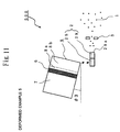
- Fig. 9 is a side view of the electrostatic atomizer 300 of a deformed example 3.
- the difference with the electrostatic atomizer 100 of Fig. 1 is a providing angle of the atomizing electrode 2 (the top end atomizing unit 29 and the trunk unit 28).
- the atomizing electrode 2 is provided horizontally, and of the cooling unit 8, the parallel-aligning direction of the cooling fins 8b and the projected height direction are both horizontal, the lower end surface of the cooling fin 8b and the top surface of the atomizing electrode 2 are provided also in parallel to both of the parallel-aligning direction of the cooling fins 8b and the projected height direction.
- the atomizing electrode 2 is provided by slanting with the angle ⁇ 1 (refer to Fig. 9 ) from the trunk unit 28 towards the top end atomizing unit 29 (provided projectedly on the long-side direction side surface of the trunk unit 28) in the direction of gravitational force.
- the size of the angle ⁇ 1 is around 5 to 30 degrees.
- the gravitational force can be used for the water delivery from the trunk unit 28 to the top end atomizing unit 29 in addition to the movement by the surface diffusion of water through the inside voids, and thus it is possible to obtain another effect that, for example, even if the condensation water 10 generated in the cooling unit 8 is little, the condensation water 10 received by the trunk unit 28 can be delivered rapidly to the top end atomizing unit 29.
- Fig. 10 is a side view of the electrostatic atomizer 400 of a deformed example 4.
- the electrostatic atomizer 400 is different from the electrostatic atomizer 300 of Fig. 9 in that the slanting direction of the atomizing electrode 2 (the top end atomizing unit 29 and the trunk unit 28) is opposite.
- the atomizing electrode 2 is provided by slanting with an angle ⁇ 2 (refer to Fig. 10 ) from the trunk unit 28 towards the top end atomizing unit 29 (provided projectedly on the long-side direction side surface of the trunk unit 28) in the direction of anti-gravitational force.
- the size of the angle ⁇ 2 is around 5 to 30 degrees.
- the electrostatic atomizer 400 in which the atomizing electrode 2 is provided like this, for example, if the humidity in the air supplied to the cooling unit 8 is high, and the condensation water 10 is dropped excessively to the trunk unit 28, it is possible to discharge the excessive water in the direction being opposite to the projected direction of the top end atomizing unit 29.
- this electrostatic atomizer 400 since the excessive water does not flow into the top end 29a of the top end atomizing unit 29 by discharging the excessive water from the opposite side of the top end atomizing unit 29, the generation of the electrostatic mist 1 is not inhibited by the excessive water, and it is possible to generate the electrostatic mist 1 properly and stably.
- the atomizing electrode 2 is provided by slanting from the trunk unit 28 towards the top end atomizing unit 29 in the direction of anti-gravitational force, since the atomizing electrode 2 is formed by the metal porous body, if the inside is not saturated with water, it is possible to deliver the water to the top end atomizing unit 29 through the inside voids (the pores) by the surface diffusion against the gravitational force.
- Fig. 11 is a side view of the electrostatic atomizer 500 of a deformed example 5.
- the difference with the electrostatic atomizer 100 of Fig. 1 is the providing angle of the cooling unit 8.
- the cooling unit 8 is provided by slanting with the angle ⁇ 3 (refer to Fig. 11 ) from the base board 8a (the base end of the cooling fins 8b) which is at the Peltier unit 6 side towards the projected end of the cooling fins 8b in the direction of gravitational force.
- the size of the angle ⁇ 3 is around 10 to 30 degrees.
- the cooling unit 8 In the electrostatic atomizer 500 in which the cooling unit 8 is provided like this, water condensed on the surfaces of the cooling fins 8b is transmitted to the lower end with being guided to the projected end side of the cooling fins 8b by the gravitational force.
- the dropping location of the water dropped from the lower ends of the cooling fins 8b can be limited to a narrow range at the projected end side of the cooling fins 8b.
- the electrostatic atomizer 100 of Fig. 1 all of the range of the projected height L4 of the cooling fins 8b is the dropping location; however in this electrostatic atomizer 500, it is possible to make the range of the dropping location of the condensation water 10 narrower than L4.
- the refore it is possible to make the short-side direction width of the trunk unit 28 of the atomizing electrode 2 smaller than L4. Namely, the short-side direction width of the trunk unit 28 can be made smaller compared with the electrostatic atomizer 100.
- the width L5 (refer to Fig. 4 ) of the short-side direction of the top surface of the trunk unit 28 exposed to the cooling fins 8b can be made smaller than the electrostatic atomizer 100.
- this electrostatic atomizer 500 can deliver the condensation water 10 received by the trunk unit 28 to the top end atomizing unit 29 more rapidly than the electrostatic atomizer 100 of Fig. 1 ; thus it is possible to obtain an effect that the time from starting the operation before the generation of the electrostatic mist 1 can be further reduced.
- the providing angle of the atomizing electrode 2 of the electrostatic atomizer 500 shown in Fig. 11 is also horizontal similarly to the electrostatic atomizer 100 of Fig. 1 ; however, the providing angle can be slanted like the deformed example 3 of Fig. 9 or the deformed example 4 of Fig. 10 , and if slanted like that, it is also possible to obtain the effect of the deformed example 3 or the deformed example 4.
- the coulomb force does not exceed the surface tension of water that forms Taylor cone, water becomes hard to leave from the top end 29a of the top end atomizing unit 29, namely, the water is hardly popped out of the top end 29a, and the generation of the electrostatic mist 1 is sometimes inhibited.
- the inside voids (the pores) of the atomizing electrode 2 is not saturated with water. Therefore, by suppressing the power distribution to the Peltier unit 6, it is preferable to control generation amount of the condensation water 10 so as not to make the atomizing electrode 2 be saturated with water.
- the configuration of the electrostatic atomizer in particular, the shape or the arrangement structure of the atomizing electrode 2 has been explained. H ereinafter, the configuration of the atomizing electrode 2 will be explained in detail.
- the atomizing electrode 2 is formed by using the foam metal which is the metal porous body as its material.
- Ceramic such as titania, mullite, silica, alumina, etc. has been used as the porous body material which works both as the water delivery function and discharge function (for example, Patent Document 1). Ceramic includes an advantage of the ability of water delivery by capillary action, good workability, superiority in the abrasion resistance against high voltage, etc.
- ceramic is the porous body material
- the inside of ceramic is relatively dense such that the inside porosity (the inclusion rate of the pores) is around 10 to 50% and the pore diameter (the outer diameter) of the pore is 0.1 to 1.0 ⁇ m, at largest 3.0 ⁇ m, so that it takes time to deliver water to be atomized to the discharging part of the top end by capillary action.
- the pores may be clogged due to impurities, water may be bridged, and water absorbing property and water delivering performance cannot be maintained high for a long period of time.
- the volume resistance rate (the electric resistance rate) of ceramic is high, the high-voltage applied on ceramic does not work sufficiently on the water to be atomized, the atomization is hard to occur, and there is also a problem that it is impossible to obtain enough amount of mist.
- the metal bar when used as the electrode at the discharging side instead of porous material, it is impossible to deliver water to the top end which is the discharging part since the metal bar does not include pores inside. Therefore, the metal bar itself is sometimes cooled to generate the condensation water directly on the top end surface; however, the water amount of the water condensed on the top end surface of the metal bar is small, and there is a problem that sufficient amount of mist cannot be obtained using only the water condensed on the top end surface of the metal bar.
- the foam metal which is the metal porous body is proposed to use as material for the atomizing electrode 2, since the foam metal is material which has low electric resistance rate (volume resistance rate) and high conductivity, while having sufficient water absorption property and water delivering performance, and thus efficiently conveys electricity to the water to be atomized.
- the foam metal is defined as the metal porous body having three-dimensional net structure.
- the thr ee-dimensional net structure is known as resin foam represented by sponge, and the foam metal has the same structure as this.
- Sintered metal is well known as the metal porous body. The different point of the foam metal from the sintered metal, the porosity of the foam metal is high and the pore diameter of the pore is large due to the three-dimensional net structure.
- the foam metal is made by adding foaming agent in the liquid mixture containing metal so-called slurry, and under the status where the mixture is foamed, by sintering at an extremely high temperature. By this operation, the foam material can be made using raw materials of various metals or alloys.
- the foam metal made like this has a continuous pore structure. Although the foam metal has been used mainly for a filter, a catalyst carrier, a fuel cell gas diffusion layer, etc., this time, it is found that the foam metal has superior feature as material of the electrode of the electrostatic atomizer.
- the most remarkable characteristic of the foam metal is high porosity.
- the porosity is also called as the void ratio showing the inclusion rate of pores, which can be evaluated by examining how much water absorption is made inside of the foam metal. This evaluation method follows the principle of Archimedes that a body immersed in a fluid is buoyed up by a force equal to the weight of the displaced fluid.
- the porosity extremely high such as 60 to 98% due to the three-dimensional net structure.
- the inside of the foam metal namely, the atomizing electrode 2 can absorb a large amount of water.
- the porosity is too large, although the water absorption property can be increased, the absorbed water might leak; thus it is preferable to set the porosity to 60 to 90% for the atomizing electrode 2.
- the porosity is around 10 to 50%, approximate 35%. Further, in case of general sintered metal which is not the foam metal, the porosity is around 50 % if it is high, so that the porosity of the foam metal is clearly high.
- the foam metal used for the atomizing electrode 2 in the electrostatic atomizers 100 to 500 of the present embodiment is structured by a sintered metal part 22 and a pore 21 which is a void part.
- a diameter of the pore 21 is defined as a pore diameter.
- the size of the pore diameter can be determined by an image taken by an electronic microscope. Further, it is possible to measure not only the pore diameter but also distribution status of pores using a mercury intrusion porosimetry or a gas adsorption measuring device.
- the pore diameter of the foam metal of the atomizing electrode 2 is good to be 10 to 1000 ⁇ m
- the foam metal having the pore diameter of 50 to 600 ⁇ m is preferable from the viewpoint of water absorption property or prevention of clogging
- the foam metal having the pore diameter of 150 to 300 ⁇ m is the most preferable considering the stiffness or the productivity (workability).
- the pore diameter is less than 10 ⁇ m like ceramic, there is a high risk of clogging since the pore diameter is too fine (too small), and the water absorption amount of such material is small. Further, it is difficult to make all the size of the pores 21 small stably in production of the foam metal. On the contr ary, if the pore diameter exceeds 1000 ⁇ m, the water absorbed through the continuous pores 21 might easily leak, which makes hard to deliver water from the trunk unit 28 to the top end atomizing unit 29.
- the water absorption amount of the foam metal used for the atomizing electrode 2 will be compared with that of the ceramic porous body which has been conventionally used for the electrode at the discharging side.
- Fig. 13 shows the results.
- Embodiment Example 1 which is the foam metal using austenitic stainless steel SUS316 as raw material
- the water absorption amount is around 0.5 g/cm 3
- Embodiment Example 2 which is the foam metal using titanium as raw material
- the water absorption amount is around 0.4 g/cm 3
- the water absorption amount is around 0.2 g/cm 3 . It is found that the foam metal has two times water absorption performance as that of ceramic.
- the foam metal having the high porosity and a large pore diameter inside has high water absorption performance compared with ceramic as shown in Fig. 13 .
- Th e high water absorption performance means the amount and the speed of inside movement of the water is also large, namely, delivery performance is also high. Therefore, the atomizing electrode 2 formed by the foam metal allows water to move rapidly to the top end atomizing unit 29 compared with the case using the ceramic. Since the water absorption amount is large, it is possible to reduce the time before starting the electrostatic atomization from starting the operation of the electrostatic atomizers 100 to 500. In addition, it is possible to prevent an event that electrostatic atomization may discontinue because the water delivery to the top end atomizing unit 29 from the trunk unit 28 is stopped temporarily, and it is possible to generate the electrostatic mist 1 properly and stably.
- the inside of the foam metal water is moved mainly by the surface diffusion through the three dimensionally continuous pores 21, so that as for the providing direction of the atomizing electrode 2, it is possible to set the top end atomizing unit 29 directed to the ceiling direction or directed horizontally, irrelevant to the direction of gravitational force. Then, since the atomizing electrode 2 is a continuous pore structure and the pore diameter of the pores 21 is large, the water can be delivered stably to the top end atomizing unit 29 for a long period of time without clogging.
- Fig. 14 shows the result of comparing the electric resistance rate of the foam metal and other porous bodies
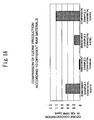
- Fig. 15 shows the result of comparing the electrostatic atomizing amount of the atomizing electrode 2 of the present embodiment formed by the foam metal and the atomizing electrode formed by ceramic and having the same shape as the atomizing electrode 2.
- the electrostatic atomizing amount means the mist generation amount showing the weight of the electrostatic mist 1 generated by the electrostatic atomizer using the above the atomizing electrode per a unit time (popped out of the atomizing electrode), and it is possible to estimate the degree of humidity elevation of the inside of a box of predetermined volume.
- the supply voltage of the high-voltage supply unit 4 is made the same in Fig. 15 .
- the electric resistance of the atomizing electrode 2 is often specified according to its material.
- the electric resistance rate of the foam metal although it is the foam, since the foam metal is absolutely metal and conductor, in both cases of Embodiment Example 1 of SUS316 in which the raw material is stainless steel and Embodiment Example 2 of titanium, electric resistance is extremely small such as around 1 ⁇ 10 -7 ⁇ m, so that the foam metal conducts electricity very well, namely, it is possible to convey the electricity efficiently to the water, with reducing the loss, and to charge the water.
- the electric resistance rate of ceramic material is large such as 1 ⁇ 10 14 ⁇ m in case of mullite shown in Comparison Example 1 and 1 ⁇ 10 12 ⁇ m in case of titania shown in Comparison Example 2, so that the ceramic material cannot be called as a conductor, but it is an intermediate between a semi-conductor and an insulator.
- the ceramic material shows the high electric resistance rate similarly to the sponge which is the resin foam of Comparison Example 3.
- the atomizing electrode 2 using the foam metal as material, it is possible to charge water more efficiently than the case using the ceramic as material.
- Na mely if the high-voltage supplied by the high-voltage supply unit 4 is the same size, when using the atomizing electrode 2 using the foam metal as material according to the present embodiment, it is possible to convey the electric current more easily to the water and to charge the water more efficiently than the case using the ceramic as material.
- the electric resistance is reduced, so that the electric power consumed by the electrostatic atomization can be smaller than the case using the ceramic as material; thus it is possible to contribute to saving of energy.
- the electrostatic atomizing amount of the atomizing electrode 2 formed by the foam metal as material is around 0.15 cc/hr per an electrode of the atomizing electrode 2 in both cases of Embodiment Example 1 using SUS316 as the raw material of the foam metal and Embodiment Example 2 using titanium.
- the electrostatic atomizing amount is smaller than Embodiment Examples using the foam metal such as 0.06 cc/hr in case of mullite shown in Comparison Example 1, and 0.08 cc/hr in case of titania shown in Comparison Example 2.
- the electrostatic atomizing amount of titania is larger than mullite; from Fig. 14 , it is found that the electric resistance rate of mullite is 2 digits lower than titania.
- Fig. 14 and Fig. 15 it is found by comparing cases using ceramic, namely, Comparison Example 1 and Comparison Example 2, that when the atomizing electrode can easily conduct electricity (the electric resistance rate is small), electricity is applied and charged efficiently to the water, Taylor cone of water formed at the top end 29a of the top end atomizing unit 29 is popped out easily by the coulomb force, and thus the electrostatic atomizing amount is increased.
- the atomizing electrode 2 formed by the foam metal is made by producing a large sheet-shaped foam metal having the thickness of around 0.5 mm to 5.0 mm and cutting the sheet-shaped foam metal to form a desired shape (the trunk unit 28 and the top end atomizing unit 29 which are continuous). Mass production is possible by laminating the sheet-shaped foam metal in the plate thickness direction and cutting out multiple pieces simultaneously. The cutting out is carried out by wire-cut or laser-cut. It is possible to process to form into the desired shape using other various kinds of processing methods such as punching by Thompson blade or press, cutting by machine, cutting by hand, bending work, etc. Although it is not used for the atomizing electrode 2, the foam metal can be jointed by welding or waxing.
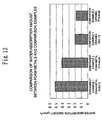
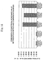
- Fig. 16 shows the comparison result of the ozone production according to different raw materials (quality of materials) of the foam metal.
- ozone is useful in its antiseptic property if the amount is appropriate, when the generation amount is excessive, the smell is felt unusual for the human from its grass-like smelling, or it sometimes works oxidation action or corrosion action on the human or the surrounding substances. Therefore, in the electrostatic atomizers 100 to 500 for releasing the electrostatic mist 1, it is desired to suppress the production amount of ozone generated by the discharge as much as possible.
- the production amount of ozone in the atomizing electrode 2 formed by the foam metal is examined by experiment.
- the contents of experiment are to examine a steady-state value of ozone concentration inside of 42 L (liter) box (42 L tank) when the predetermined same size of high voltage is applied on the atomizing electrode 2.
- the foam metal shown in Comparison Example 4 is SUS304 (nickel content of 8 to 10.5%, chrome content of 18 to 20%) which is generally well-known as austenitic stainless steel, and as the ozone production in this case, the ozone concentration inside of 42 L tank is 1.2 ppm.
- SUS304 nickel content of 8 to 10.5%, chrome content of 18 to 20%
- the ozone concentration inside of 42 L tank is 1.2 ppm.
- the ozone concentration of 42 L tank is 0.7 ppm, which corresponds to around 60% compared with Comparison Example 1 using SUS304.
- Embodiment Example 2 shown in Fig. 16 formed by the foam metal using titanium as raw material is the least such that the ozone concentration of the 42 L tank is 0.03 ppm, that is, 1/40 of Comparison Example 4 (SUS304) and 1/23 of Embodiment Example 1 (SUS316); the ozone production can be largely suppressed.
- Embodiment Example 3 formed by the foam metal using nickel as raw material is used, the ozone concentration inside of the 42 L tank is 0.3 ppm, so that suppressant effect of ozone generation cannot be obtained as much as Embodiment Example 2 (titanium); however, suppressant effect of ozone generation is larger than Embodiment Example 1 (SUS316).
- radical activated species
- the chemical reactivity of such radical is extremely high, and the radical is a very unstable substance because it is active. Since it immediately reacts with molecules in the air such as oxygen and nitrogen, etc., it is extremely short-lived in the air, so that it disappears almost instantly even if it is generated. E ven if the radical is generated, they would not be released with the electrostatic mist 1, and the electrostatic mist 1 would not include radical.
- the most suitable material of the atomizing electrode 2 is the foam metal using titanium as raw material.
- the foam metal using SUS316, titanium, or nickel as raw material it is possible to prevent electric corrosion or electric abrasion caused by applying high voltage, and it is possible to maintain the shape of the atomizing electrode 2, in particular, the sharpened shape of the top end atomizing unit 29 for a long period of time. Therefore, it is also possible to obtain the effect that the electrostatic atomization can be stably done for a long period of time. This effect is remarkable from the feature of, in particular, material using titanium as raw material.
- the foam metal has the three-dimensional net structure in which the porosity is high and the pore diameter is large, the foam metal has high water absorption property and high delivering property (the property that the moving speed of water is high). Further, by using such property, it has been explained that the foam metal is suitable as material of the atomizing electrode 2 of the atomizing electrode 2 shown in the present embodiment.
- the foam metal is suitable as material of the atomizing electrode 2 of the atomizing electrode 2 shown in the present embodiment.
- the oxidation treatment can be done by exposing the foam metal in the oxygen atmosphere.
- the increase of hydrophilic property by the oxidation treatment is remarkable when titanium is used as raw material.
- the surface layer has property being close to titanium oxide. Since water acid radical (OH group) is made on the outermost surface by reacting with the surrounding water when titanium oxide receives energy such as ultraviolet, etc., the titanium oxide has high affinity for water (is high hydrophilic). Therefore, when the water is moved by the surface diffusion, the water broadens and proceeds without stopping, and the water inside of the foam metal can be moved efficiently and rapidly.
- the foam metal using titanium as raw material the result is obtained that the moving speed of the water of the case where the oxidation treatment is done is about five times as much as that of the case where the oxidation treatment is not done.
- the oxidation treatment is done not only on the outer surface of the atomizing electrode 2 formed by the foam metal, but also on the surface facing the inside pores 21 by passing through the continuous pores because of the continuous pore structure having a high porosity and a large pore diameter.
- hydrophilic property increases in all the surfaces of the metal part 22 including the inside surface facing the pores 21, so that the moving speed of water can be increased. Therefore, it is possible to reduce the time from starting the operation of the electrostatic atomizers 100 to 50 until the release of the electrostatic mist 1.
- one of the characteristics of the atomizing electrode 2 of the electrostatic atomizer related to the present embodiment is that the atomizing electrode 2 is formed by the foam metal having the three-dimensional net structure as material. Therefore, since the water absorption amount is large, and the moving speed of water is high, it takes short from starting the operation of the electrostatic atomizer until starting atomization (the electrostatic mist 1 is released). Then, since the foam metal has the low electric resistance rate and is excellent in electric conductivity, it is possible to have an effect that the electricity can be efficiently applied to the water to be atomized and the water can be charged, and the atomizing amount is increased.
- the atomizing electrode 2 is formed by the foam metal on the surface of which the oxidation treatment is done after sinitering as material, the hydrophilic property of the inside surface is increased, and it is possible to have an effect that the moving speed of water is further improved.
- the foam metal having the three-dimensional net structure which has been explained up to the above, because of its high water absorption property and high delivering property, it is applicable to not only the atomizing electrode 2 of the electrostatic atomizers 100 to 500 shown in the present embodiment, but also to the electrostatic atomizer of another embodiment; if the foam metal is used for an electrode which also works for water deliverer to the discharging part, it is possible to obtain the same effect as the atomizing electrode 2 of the present embodiment.
- water of the water reserving unit which is the water supply means is delivered to the upper end of an erect delivering body made by ceramic porous body by capillary action, and Taylor cone of water is formed on the upper end which is sharpened in a pin-shape to generate mist.
- the delivering body corresponding to the atomizing electrode 2
- the foam metal which has been explained up to the above, the delivering speed of water is remarkably increased, so that it is possible to reduce the time from starting the operation before electrostatic atomization compared with the case using the delivering body formed by ceramic.
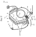
- FIG. 17 is a cross sectional view of the air conditioner 50 including either of the electrostatic atomizers 100 to 500.
- the air conditioner 50 is a general wall-hanging type.
- the air conditioner 50 is provided with a suction opening 41 for sucking the indoor air, a supply opening 42 for blowing out conditioned air to the indoors, a heat exchanger 51 (including an upper front heat exchanger 51a, a lower front heat exchanger 51b, and a back heat exchanger 51 c) which is an inverted V shape and for generating conditioned air from the indoor air, a drain pan 40 (two pans) for receiving the water condensed by the heat exchanger 51, and a blower fan 43.
- the indoor air flown from the suction opening 41 located above the main body of the air conditioner 50 by the rotation of the blower fan 43 is heat exchanged with the refrigerant of the refrigerating cycle on passing the heat exchanger 51 to adjust the temperature and the humidity.
- the h eat-exchanged indoor air passes through the blower fan 43, and is blown out to the indoors as the conditioned air from the supply opening 42 positioned below.
- the supply opening 42 is provided with a horizontal wind direction board 44 which can change the wind direction of the conditioned air to be blown out and a vertical wind direction board 45, and the blowing direction of the blowing airflow is adjusted.
- the horizontal wind direction board 44 which can change the horizontal air direction of the blowing airflow is positioned at the upstream side of the vertical wind direction board 45 which can change the vertical air direction of the blowing airflow. Further, the condensation water of the heat exchanger 51 collected by the drain pan 40 is discharged to the outdoor through a drain hose, not illustrated.
- either of the electrostatic atomizers 100 to 500 is provided at either of the windward side (the upstream side) of the lower front heat exchanger 51b, or the windward side (the upstream side) of the back heat exchanger 51c and also above the drain pan 40.
- the drain pan 40 receives such excessive water and discharges to the outdoors together with the condensation water of the heat exchanger 51. Therefore, there is no probability of leakage of the excessive water of either of the provided electrostatic atomizers 100 to 500 to the indoors.
- the air conditioner 50 By providing the air conditioner 50 with either of the electrostatic atomizers 100 to 500, a large amount of the electrostatic mist 1 released from the electrostatic atomizer is made pass through the heat exchanger 51 together with the indoor air sucked from the suction opening 41 and can be released to the indoors together with the conditioned air from the supply opening 42.
- the electrostatic mist 1 of nanometer size generated in either of the electrostatic atomizers 100 to 500 is released to the indoors together with the conditioned air from the supply opening 42 of the air conditioner 50, since the electrostatic mist 1 is charged negatively, the electrostatic mist 1 tends to approach the human body having a potential difference. Then, since the size of the electrostatic mist 1 is smaller than the corneocyte of the human cell, the electrostatic mist 1 is permeated in exposed skin such as a face or a neck, etc., and gives moisturizing effect to the user. By this operation, the following effect can be obtained.
- the increase of the moisture of the exposed part of skin such as a face or a neck of the user, etc. with 25% corresponds to the increase of the indoor humidity with around 20%RH.
- the increase of around 20%RH of the indoor humidity corresponds to the increase of around 1 degree of the sensory temperature of human.
- the power consumption amount of the air conditioner 50 can be reduced with around 10%.
- the parallel-aligning direction of the cooling fins 8b or the fins of the heat radiating part 7 should be in the horizontal direction of the main body of the air conditioner 50.
- the sucked airflow from the suction opening 41 is made to flow along the fins, and the heat radiation of the heat radiating part 7 is promoted.
- the heat radiating part 7 is arranged so as to face the heat exchanger 51, the flowing amount of airflow (the indoor sucked air) passing the heat radiating part 7 is increased, and the heat radiation is further promoted.
- the top end atomizing unit 29 is provided on the long-side direction side surface of the trunk unit 28 at the side of the heat radiating part 7 so as to be projected in the direction being opposite to the projected direction of the cooling fins 8b.
- the electrostatic mist 1 is mounted on the airflow having a large flowing amount passing the heat radiating part 7 and can be guided rapidly and steadily to the supply opening 42, and accordingly it is possible to release plenty of the electrostatic mist 1 from the supply opening 42 in a short time from starting the operation of the air conditioner 50.
- the atomizing electrode 2 is formed by the foam metal using reducing metal, in particular, titanium as raw material, thereby suppressing the production amount of ozone generated by discharge.
- reducing metal in particular, titanium as raw material.
- the radical does not work oxidation action on the human body of the user who requests the moisturizing effect. Although it is char ged, pure water of nanometer size permeates the skin of user, so that the moisturizing effect can be increased, without giving harmful effect on the skin.
- the foam metal having the three-dimensional net structure is used as material of the atomizing electrode 2. If, for example, another porous body such as ceramic, nonfoam general sintered metal, or resin foam, etc. which delivers water by the capillary action is used for forming the atomizing electrode 2, various effects obtained by using the foam metal cannot be obtained.
- the electrostatic atomizer related to the present invention can guide rapidly and steadily water dropped from the water supply means to the top end atomizing unit of the water applying electrode, and it is possible to have an effect to generate stably a large amount of the electrostatic mist in a short time from starting the operation.
Landscapes
- Chemical & Material Sciences (AREA)
- Engineering & Computer Science (AREA)
- Dispersion Chemistry (AREA)
- Combustion & Propulsion (AREA)
- Mechanical Engineering (AREA)
- General Engineering & Computer Science (AREA)
- Electrostatic Spraying Apparatus (AREA)
- Devices For Blowing Cold Air, Devices For Blowing Warm Air, And Means For Preventing Water Condensation In Air Conditioning Units (AREA)
Applications Claiming Priority (1)
| Application Number | Priority Date | Filing Date | Title |
|---|---|---|---|
| JP2009142787A JP4818399B2 (ja) | 2009-06-15 | 2009-06-15 | 静電霧化装置及び空気調和機 |
Publications (2)
| Publication Number | Publication Date |
|---|---|
| EP2263804A1 EP2263804A1 (en) | 2010-12-22 |
| EP2263804B1 true EP2263804B1 (en) | 2016-04-13 |
Family
ID=42236489
Family Applications (1)
| Application Number | Title | Priority Date | Filing Date |
|---|---|---|---|
| EP10004941.0A Not-in-force EP2263804B1 (en) | 2009-06-15 | 2010-05-10 | Electrostatic atomizer and air conditioner |
Country Status (5)
| Country | Link |
|---|---|
| US (1) | US9132439B2 (enExample) |
| EP (1) | EP2263804B1 (enExample) |
| JP (1) | JP4818399B2 (enExample) |
| CN (1) | CN101920230B (enExample) |
| ES (1) | ES2571881T3 (enExample) |
Families Citing this family (17)
| Publication number | Priority date | Publication date | Assignee | Title |
|---|---|---|---|---|
| JP4805421B2 (ja) * | 2011-03-11 | 2011-11-02 | 三菱電機株式会社 | 静電霧化装置及び空気調和機 |
| JP2014040977A (ja) * | 2012-08-23 | 2014-03-06 | Toshiba Corp | 空気調和機 |
| US9816715B2 (en) * | 2012-09-18 | 2017-11-14 | Mitsubishi Electric Corporation | Humidifier and air-conditioning apparatus with humidifier |
| CN103900155B (zh) * | 2012-12-26 | 2017-06-16 | 广州市拓丰电器有限公司 | 水离子空气净化器 |
| JP6080965B2 (ja) * | 2013-09-18 | 2017-02-15 | 三菱電機株式会社 | 加湿装置、及び加湿装置を備えた空気調和機 |
| JP6319233B2 (ja) * | 2015-08-28 | 2018-05-09 | トヨタ自動車株式会社 | 静電微粒化式塗装装置及び塗装方法 |
| CN105091176A (zh) * | 2015-08-31 | 2015-11-25 | 广东美的制冷设备有限公司 | 蓄湿装置及空调器 |
| JP6076553B1 (ja) * | 2016-02-09 | 2017-02-08 | 三菱電機株式会社 | 加湿装置及び空気調和機 |
| US10724131B2 (en) * | 2016-04-12 | 2020-07-28 | United Technologies Corporation | Light weight component and method of making |
| US10619949B2 (en) | 2016-04-12 | 2020-04-14 | United Technologies Corporation | Light weight housing for internal component with integrated thermal management features and method of making |
| US10399117B2 (en) | 2016-04-12 | 2019-09-03 | United Technologies Corporation | Method of making light weight component with internal metallic foam and polymer reinforcement |
| US10335850B2 (en) | 2016-04-12 | 2019-07-02 | United Technologies Corporation | Light weight housing for internal component and method of making |
| US12152807B2 (en) * | 2018-02-12 | 2024-11-26 | Noritake Co., Limited | Liquid atomizing apparatus |
| CN111174283B (zh) * | 2018-10-24 | 2022-01-21 | 青岛海尔空调器有限总公司 | 一种可移动的空调、空调集群及智能家居系统 |
| KR102173228B1 (ko) * | 2019-01-04 | 2020-11-03 | 한국과학기술원 | 연성 평판 진동형 히트파이프 및 이의 제작 방법 |
| CN109631197A (zh) * | 2019-01-30 | 2019-04-16 | 肖金坚 | 一种具备静电除尘功能的空气净化系统 |
| CN114247575B (zh) * | 2020-09-22 | 2025-05-27 | 平流层复合水离子(深圳)有限公司 | 等距电极自积水有益物质发生装置及具有该装置的阵列 |
Family Cites Families (48)
| Publication number | Priority date | Publication date | Assignee | Title |
|---|---|---|---|---|
| JPS5872824A (ja) * | 1981-10-27 | 1983-04-30 | Mitsubishi Heavy Ind Ltd | 空調機の加湿装置 |
| JPH03275112A (ja) * | 1990-03-23 | 1991-12-05 | Mitsubishi Electric Corp | 電子除湿装置 |
| JP3032925B2 (ja) * | 1992-09-25 | 2000-04-17 | 富士写真フイルム株式会社 | 非水電池 |
| JPH07167455A (ja) | 1993-12-13 | 1995-07-04 | Aisin Seiki Co Ltd | 除湿装置 |
| US5848351A (en) | 1995-04-03 | 1998-12-08 | Mitsubishi Materials Corporation | Porous metallic material having high specific surface area, method of producing the same, porous metallic plate material and electrode for alkaline secondary battery |
| KR970073821A (ko) | 1995-09-27 | 1997-12-10 | 아키모토 유미 | 다공질 소결금속판의 제조방법 및 제조장치 |
| CN1213826C (zh) * | 1995-11-20 | 2005-08-10 | 三菱麻铁里亚尔株式会社 | 制造烧结多孔金属板的方法和设备 |
| JP3844859B2 (ja) | 1997-11-12 | 2006-11-15 | 三菱電機株式会社 | 除湿装置 |
| JP4032954B2 (ja) * | 2002-07-05 | 2008-01-16 | ソニー株式会社 | 冷却装置、電子機器装置、音響装置及び冷却装置の製造方法 |
| JP2004255517A (ja) | 2003-02-26 | 2004-09-16 | Suzuki Motor Corp | 放電加工用の消耗電極部材 |
| JP4195989B2 (ja) | 2003-05-27 | 2008-12-17 | パナソニック電工株式会社 | 静電霧化装置及びこれを備えた空気清浄機 |
| CN1774301B (zh) * | 2003-05-27 | 2012-07-04 | 松下电器产业株式会社 | 带电微粒子水和形成其中分散有带电微粒子水的雾状物的环境的方法 |
| FR2862007B1 (fr) * | 2003-11-12 | 2005-12-23 | Commissariat Energie Atomique | Dispositif microfluidique muni d'un nez d'electronebulisation. |
| FR2862006B1 (fr) * | 2003-11-12 | 2006-01-27 | Univ Lille Sciences Tech | Sources d'electronebulisation planaires sur le modele d'une plume de calligraphie et leur fabrication. |
| JP2005192822A (ja) | 2004-01-08 | 2005-07-21 | Matsushita Electric Ind Co Ltd | 浄化方法と浄化装置 |
| ATE520469T1 (de) * | 2004-04-08 | 2011-09-15 | Panasonic Elec Works Co Ltd | Elektrostatischer zerstäuber |
| JP4625267B2 (ja) | 2004-04-08 | 2011-02-02 | パナソニック電工株式会社 | 静電霧化装置 |
| JP3952052B2 (ja) * | 2004-09-06 | 2007-08-01 | 松下電工株式会社 | 静電霧化装置 |
| JP4123211B2 (ja) * | 2004-09-24 | 2008-07-23 | 松下電器産業株式会社 | 空気調和機 |
| GB0421386D0 (en) * | 2004-09-25 | 2004-10-27 | Scion Sprays Ltd | Electrostatic atomisers and mixing arrangements |
| CN1268460C (zh) * | 2004-11-22 | 2006-08-09 | 广州有色金属研究院 | 一种金属多孔材料的制备方法 |
| JP4701746B2 (ja) | 2005-02-23 | 2011-06-15 | パナソニック電工株式会社 | 空気清浄機能付き空気調和機 |
| US20060201162A1 (en) * | 2005-03-11 | 2006-09-14 | Hsieh Hsin-Mao | Dehumidifying device |
| JP2007101140A (ja) | 2005-10-07 | 2007-04-19 | Daikin Ind Ltd | 空気調和機 |
| JP4674541B2 (ja) * | 2005-12-22 | 2011-04-20 | パナソニック電工株式会社 | 静電霧化装置及び静電霧化装置を備えた食品保管庫 |
| JP2007273100A (ja) | 2006-03-30 | 2007-10-18 | Equos Research Co Ltd | 燃料電池のセル及びスタック並びに燃料電池システム |
| JP2007278569A (ja) | 2006-04-05 | 2007-10-25 | Matsushita Electric Ind Co Ltd | 冷蔵庫 |
| JP4736915B2 (ja) | 2006-04-07 | 2011-07-27 | パナソニック電工株式会社 | 静電霧化装置 |
| JP4023512B1 (ja) * | 2006-06-15 | 2007-12-19 | ダイキン工業株式会社 | 液処理装置、空気調和装置、及び加湿器 |
| JP2008142661A (ja) | 2006-12-12 | 2008-06-26 | Daikin Ind Ltd | 静電噴霧装置 |
| JP4706630B2 (ja) * | 2006-12-15 | 2011-06-22 | パナソニック電工株式会社 | 静電霧化装置 |
| JP4366405B2 (ja) * | 2007-01-31 | 2009-11-18 | 日立アプライアンス株式会社 | 空気調和機 |
| JP2008190813A (ja) * | 2007-02-07 | 2008-08-21 | Hitachi Appliances Inc | 静電霧化装置を搭載した空気調和機 |
| JP2008212887A (ja) | 2007-03-07 | 2008-09-18 | Techno Frontier:Kk | 静電霧化装置 |
| JP2007263551A (ja) * | 2007-04-05 | 2007-10-11 | Matsushita Electric Works Ltd | 空気調和機 |
| JP3986550B2 (ja) | 2007-04-06 | 2007-10-03 | 松下電工株式会社 | 静電霧化装置 |
| JP3986549B2 (ja) | 2007-04-06 | 2007-10-03 | 松下電工株式会社 | 静電霧化装置 |
| JP4036887B2 (ja) | 2007-04-06 | 2008-01-23 | 松下電工株式会社 | 静電霧化装置 |
| JP5027594B2 (ja) | 2007-08-20 | 2012-09-19 | パナソニック株式会社 | 静電霧化装置 |
| JP2009090192A (ja) * | 2007-10-05 | 2009-04-30 | Panasonic Electric Works Co Ltd | 静電霧化装置 |
| JP5183274B2 (ja) | 2007-11-09 | 2013-04-17 | 日立アプライアンス株式会社 | 空気調和機 |
| JP2009128642A (ja) * | 2007-11-22 | 2009-06-11 | Sharp Corp | 帯電装置および画像形成装置 |
| JP4371173B2 (ja) * | 2008-09-25 | 2009-11-25 | パナソニック電工株式会社 | 静電霧化装置 |
| JP4321660B2 (ja) | 2008-09-25 | 2009-08-26 | パナソニック電工株式会社 | 静電霧化装置 |
| JP4379536B2 (ja) | 2008-09-25 | 2009-12-09 | パナソニック電工株式会社 | 静電霧化装置 |
| ES2585089T3 (es) * | 2009-03-27 | 2016-10-03 | Mitsubishi Electric Corporation | Aparato de atomización electrostática, dispositivo, acondicionador de aire y refrigerador |
| JP5686504B2 (ja) * | 2009-06-15 | 2015-03-18 | 三菱電機株式会社 | 静電霧化装置及び空気調和機 |
| JP5377412B2 (ja) * | 2010-06-04 | 2013-12-25 | 三菱電機株式会社 | 加湿装置 |
-
2009
- 2009-06-15 JP JP2009142787A patent/JP4818399B2/ja active Active
-
2010
- 2010-02-26 CN CN201010126093.4A patent/CN101920230B/zh not_active Expired - Fee Related
- 2010-05-10 ES ES10004941T patent/ES2571881T3/es active Active
- 2010-05-10 EP EP10004941.0A patent/EP2263804B1/en not_active Not-in-force
- 2010-05-18 US US12/782,179 patent/US9132439B2/en not_active Expired - Fee Related
Also Published As
| Publication number | Publication date |
|---|---|
| US20100313580A1 (en) | 2010-12-16 |
| ES2571881T3 (es) | 2016-05-27 |
| CN101920230B (zh) | 2015-06-17 |
| CN101920230A (zh) | 2010-12-22 |
| EP2263804A1 (en) | 2010-12-22 |
| JP4818399B2 (ja) | 2011-11-16 |
| JP2010284626A (ja) | 2010-12-24 |
| US9132439B2 (en) | 2015-09-15 |
Similar Documents
| Publication | Publication Date | Title |
|---|---|---|
| EP2263804B1 (en) | Electrostatic atomizer and air conditioner | |
| JP5955395B2 (ja) | 加湿装置及び加湿装置を備えた空気調和機 | |
| JP5686504B2 (ja) | 静電霧化装置及び空気調和機 | |
| US20160146483A1 (en) | Humidifier and air-conditioning apparatus including humidifier | |
| JP5646068B2 (ja) | 加湿装置 | |
| US10746419B2 (en) | Humidifier and air-conditioning apparatus | |
| JP6076544B2 (ja) | 加湿装置、及び加湿装置を備えた空気調和機 | |
| US9777935B2 (en) | Humidifier and air-conditioning apparatus including the same | |
| JP5574636B2 (ja) | 静電霧化装置及び空気調和機 | |
| JP5317883B2 (ja) | 空気調和機 | |
| JP4805421B2 (ja) | 静電霧化装置及び空気調和機 | |
| JP4922596B2 (ja) | 空調用霧発生装置 | |
| JP4841700B2 (ja) | 静電霧化装置及び空気調和機 | |
| JP4841698B2 (ja) | 静電霧化装置及び空気調和機 | |
| JP4841699B2 (ja) | 空気調和機 | |
| JP5159722B2 (ja) | 静電霧化装置及び空気調和機 | |
| JP5627639B2 (ja) | 静電霧化装置及び空気調和機 | |
| JP5213811B2 (ja) | 静電霧化装置及び空気調和機 | |
| JP2011161309A (ja) | 微粒化ノズル装置 | |
| JP5159742B2 (ja) | 静電霧化装置および空気調和機 | |
| JP4841701B2 (ja) | 静電霧化装置及び空気調和機 | |
| JP5586769B2 (ja) | 空気調和機 | |
| JP2012021763A (ja) | 空気調和機 | |
| JP5417289B2 (ja) | 空気調和機 |
Legal Events
| Date | Code | Title | Description |
|---|---|---|---|
| PUAI | Public reference made under article 153(3) epc to a published international application that has entered the european phase |
Free format text: ORIGINAL CODE: 0009012 |
|
| AK | Designated contracting states |
Kind code of ref document: A1 Designated state(s): AL AT BE BG CH CY CZ DE DK EE ES FI FR GB GR HR HU IE IS IT LI LT LU LV MC MK MT NL NO PL PT RO SE SI SK SM TR |
|
| AX | Request for extension of the european patent |
Extension state: BA ME RS |
|
| 17P | Request for examination filed |
Effective date: 20110610 |
|
| 17Q | First examination report despatched |
Effective date: 20120824 |
|
| REG | Reference to a national code |
Ref country code: DE Ref legal event code: R079 Ref document number: 602010032171 Country of ref document: DE Free format text: PREVIOUS MAIN CLASS: B05B0005057000 Ipc: F24F0006120000 |
|
| RIC1 | Information provided on ipc code assigned before grant |
Ipc: B05B 5/057 20060101ALI20150820BHEP Ipc: B05B 5/16 20060101ALI20150820BHEP Ipc: F24F 6/12 20060101AFI20150820BHEP |
|
| GRAP | Despatch of communication of intention to grant a patent |
Free format text: ORIGINAL CODE: EPIDOSNIGR1 |
|
| INTG | Intention to grant announced |
Effective date: 20151012 |
|
| GRAS | Grant fee paid |
Free format text: ORIGINAL CODE: EPIDOSNIGR3 |
|
| GRAA | (expected) grant |
Free format text: ORIGINAL CODE: 0009210 |
|
| AK | Designated contracting states |
Kind code of ref document: B1 Designated state(s): AL AT BE BG CH CY CZ DE DK EE ES FI FR GB GR HR HU IE IS IT LI LT LU LV MC MK MT NL NO PL PT RO SE SI SK SM TR |
|
| REG | Reference to a national code |
Ref country code: GB Ref legal event code: FG4D |
|
| REG | Reference to a national code |
Ref country code: AT Ref legal event code: REF Ref document number: 790572 Country of ref document: AT Kind code of ref document: T Effective date: 20160415 Ref country code: CH Ref legal event code: EP |
|
| REG | Reference to a national code |
Ref country code: IE Ref legal event code: FG4D |
|
| REG | Reference to a national code |
Ref country code: DE Ref legal event code: R096 Ref document number: 602010032171 Country of ref document: DE |
|
| REG | Reference to a national code |
Ref country code: ES Ref legal event code: FG2A Ref document number: 2571881 Country of ref document: ES Kind code of ref document: T3 Effective date: 20160527 |
|
| REG | Reference to a national code |
Ref country code: LT Ref legal event code: MG4D |
|
| PG25 | Lapsed in a contracting state [announced via postgrant information from national office to epo] |
Ref country code: BE Free format text: LAPSE BECAUSE OF NON-PAYMENT OF DUE FEES Effective date: 20160531 |
|
| REG | Reference to a national code |
Ref country code: AT Ref legal event code: MK05 Ref document number: 790572 Country of ref document: AT Kind code of ref document: T Effective date: 20160413 |
|
| REG | Reference to a national code |
Ref country code: NL Ref legal event code: MP Effective date: 20160413 |
|
| PG25 | Lapsed in a contracting state [announced via postgrant information from national office to epo] |
Ref country code: FI Free format text: LAPSE BECAUSE OF FAILURE TO SUBMIT A TRANSLATION OF THE DESCRIPTION OR TO PAY THE FEE WITHIN THE PRESCRIBED TIME-LIMIT Effective date: 20160413 Ref country code: PL Free format text: LAPSE BECAUSE OF FAILURE TO SUBMIT A TRANSLATION OF THE DESCRIPTION OR TO PAY THE FEE WITHIN THE PRESCRIBED TIME-LIMIT Effective date: 20160413 Ref country code: NL Free format text: LAPSE BECAUSE OF FAILURE TO SUBMIT A TRANSLATION OF THE DESCRIPTION OR TO PAY THE FEE WITHIN THE PRESCRIBED TIME-LIMIT Effective date: 20160413 Ref country code: NO Free format text: LAPSE BECAUSE OF FAILURE TO SUBMIT A TRANSLATION OF THE DESCRIPTION OR TO PAY THE FEE WITHIN THE PRESCRIBED TIME-LIMIT Effective date: 20160713 Ref country code: LT Free format text: LAPSE BECAUSE OF FAILURE TO SUBMIT A TRANSLATION OF THE DESCRIPTION OR TO PAY THE FEE WITHIN THE PRESCRIBED TIME-LIMIT Effective date: 20160413 |
|
| PG25 | Lapsed in a contracting state [announced via postgrant information from national office to epo] |
Ref country code: AT Free format text: LAPSE BECAUSE OF FAILURE TO SUBMIT A TRANSLATION OF THE DESCRIPTION OR TO PAY THE FEE WITHIN THE PRESCRIBED TIME-LIMIT Effective date: 20160413 Ref country code: LV Free format text: LAPSE BECAUSE OF FAILURE TO SUBMIT A TRANSLATION OF THE DESCRIPTION OR TO PAY THE FEE WITHIN THE PRESCRIBED TIME-LIMIT Effective date: 20160413 Ref country code: PT Free format text: LAPSE BECAUSE OF FAILURE TO SUBMIT A TRANSLATION OF THE DESCRIPTION OR TO PAY THE FEE WITHIN THE PRESCRIBED TIME-LIMIT Effective date: 20160816 Ref country code: SE Free format text: LAPSE BECAUSE OF FAILURE TO SUBMIT A TRANSLATION OF THE DESCRIPTION OR TO PAY THE FEE WITHIN THE PRESCRIBED TIME-LIMIT Effective date: 20160413 Ref country code: GR Free format text: LAPSE BECAUSE OF FAILURE TO SUBMIT A TRANSLATION OF THE DESCRIPTION OR TO PAY THE FEE WITHIN THE PRESCRIBED TIME-LIMIT Effective date: 20160714 Ref country code: HR Free format text: LAPSE BECAUSE OF FAILURE TO SUBMIT A TRANSLATION OF THE DESCRIPTION OR TO PAY THE FEE WITHIN THE PRESCRIBED TIME-LIMIT Effective date: 20160413 |
|
| REG | Reference to a national code |
Ref country code: DE Ref legal event code: R119 Ref document number: 602010032171 Country of ref document: DE |
|
| PG25 | Lapsed in a contracting state [announced via postgrant information from national office to epo] |
Ref country code: BE Free format text: LAPSE BECAUSE OF FAILURE TO SUBMIT A TRANSLATION OF THE DESCRIPTION OR TO PAY THE FEE WITHIN THE PRESCRIBED TIME-LIMIT Effective date: 20160413 |
|
| REG | Reference to a national code |
Ref country code: CH Ref legal event code: PL |
|
| PG25 | Lapsed in a contracting state [announced via postgrant information from national office to epo] |
Ref country code: EE Free format text: LAPSE BECAUSE OF FAILURE TO SUBMIT A TRANSLATION OF THE DESCRIPTION OR TO PAY THE FEE WITHIN THE PRESCRIBED TIME-LIMIT Effective date: 20160413 Ref country code: SK Free format text: LAPSE BECAUSE OF FAILURE TO SUBMIT A TRANSLATION OF THE DESCRIPTION OR TO PAY THE FEE WITHIN THE PRESCRIBED TIME-LIMIT Effective date: 20160413 Ref country code: DK Free format text: LAPSE BECAUSE OF FAILURE TO SUBMIT A TRANSLATION OF THE DESCRIPTION OR TO PAY THE FEE WITHIN THE PRESCRIBED TIME-LIMIT Effective date: 20160413 Ref country code: CZ Free format text: LAPSE BECAUSE OF FAILURE TO SUBMIT A TRANSLATION OF THE DESCRIPTION OR TO PAY THE FEE WITHIN THE PRESCRIBED TIME-LIMIT Effective date: 20160413 Ref country code: RO Free format text: LAPSE BECAUSE OF FAILURE TO SUBMIT A TRANSLATION OF THE DESCRIPTION OR TO PAY THE FEE WITHIN THE PRESCRIBED TIME-LIMIT Effective date: 20160413 Ref country code: MC Free format text: LAPSE BECAUSE OF FAILURE TO SUBMIT A TRANSLATION OF THE DESCRIPTION OR TO PAY THE FEE WITHIN THE PRESCRIBED TIME-LIMIT Effective date: 20160413 Ref country code: LI Free format text: LAPSE BECAUSE OF NON-PAYMENT OF DUE FEES Effective date: 20160531 Ref country code: CH Free format text: LAPSE BECAUSE OF NON-PAYMENT OF DUE FEES Effective date: 20160531 |
|
| PLBE | No opposition filed within time limit |
Free format text: ORIGINAL CODE: 0009261 |
|
| STAA | Information on the status of an ep patent application or granted ep patent |
Free format text: STATUS: NO OPPOSITION FILED WITHIN TIME LIMIT |
|
| REG | Reference to a national code |
Ref country code: IE Ref legal event code: MM4A |
|
| PG25 | Lapsed in a contracting state [announced via postgrant information from national office to epo] |
Ref country code: SM Free format text: LAPSE BECAUSE OF FAILURE TO SUBMIT A TRANSLATION OF THE DESCRIPTION OR TO PAY THE FEE WITHIN THE PRESCRIBED TIME-LIMIT Effective date: 20160413 |
|
| REG | Reference to a national code |
Ref country code: FR Ref legal event code: ST Effective date: 20170131 |
|
| 26N | No opposition filed |
Effective date: 20170116 |
|
| GBPC | Gb: european patent ceased through non-payment of renewal fee |
Effective date: 20160713 |
|
| PG25 | Lapsed in a contracting state [announced via postgrant information from national office to epo] |
Ref country code: FR Free format text: LAPSE BECAUSE OF NON-PAYMENT OF DUE FEES Effective date: 20160613 Ref country code: DE Free format text: LAPSE BECAUSE OF NON-PAYMENT OF DUE FEES Effective date: 20161201 |
|
| PG25 | Lapsed in a contracting state [announced via postgrant information from national office to epo] |
Ref country code: SI Free format text: LAPSE BECAUSE OF FAILURE TO SUBMIT A TRANSLATION OF THE DESCRIPTION OR TO PAY THE FEE WITHIN THE PRESCRIBED TIME-LIMIT Effective date: 20160413 Ref country code: GB Free format text: LAPSE BECAUSE OF NON-PAYMENT OF DUE FEES Effective date: 20160713 Ref country code: IE Free format text: LAPSE BECAUSE OF NON-PAYMENT OF DUE FEES Effective date: 20160510 |
|
| REG | Reference to a national code |
Ref country code: ES Ref legal event code: GC2A Effective date: 20180306 |
|
| PG25 | Lapsed in a contracting state [announced via postgrant information from national office to epo] |
Ref country code: HU Free format text: LAPSE BECAUSE OF FAILURE TO SUBMIT A TRANSLATION OF THE DESCRIPTION OR TO PAY THE FEE WITHIN THE PRESCRIBED TIME-LIMIT; INVALID AB INITIO Effective date: 20100510 Ref country code: CY Free format text: LAPSE BECAUSE OF FAILURE TO SUBMIT A TRANSLATION OF THE DESCRIPTION OR TO PAY THE FEE WITHIN THE PRESCRIBED TIME-LIMIT Effective date: 20160413 |
|
| PG25 | Lapsed in a contracting state [announced via postgrant information from national office to epo] |
Ref country code: TR Free format text: LAPSE BECAUSE OF FAILURE TO SUBMIT A TRANSLATION OF THE DESCRIPTION OR TO PAY THE FEE WITHIN THE PRESCRIBED TIME-LIMIT Effective date: 20160413 Ref country code: LU Free format text: LAPSE BECAUSE OF NON-PAYMENT OF DUE FEES Effective date: 20160510 Ref country code: MK Free format text: LAPSE BECAUSE OF FAILURE TO SUBMIT A TRANSLATION OF THE DESCRIPTION OR TO PAY THE FEE WITHIN THE PRESCRIBED TIME-LIMIT Effective date: 20160413 Ref country code: MT Free format text: LAPSE BECAUSE OF NON-PAYMENT OF DUE FEES Effective date: 20160531 Ref country code: IS Free format text: LAPSE BECAUSE OF FAILURE TO SUBMIT A TRANSLATION OF THE DESCRIPTION OR TO PAY THE FEE WITHIN THE PRESCRIBED TIME-LIMIT Effective date: 20160413 |
|
| PG25 | Lapsed in a contracting state [announced via postgrant information from national office to epo] |
Ref country code: BG Free format text: LAPSE BECAUSE OF FAILURE TO SUBMIT A TRANSLATION OF THE DESCRIPTION OR TO PAY THE FEE WITHIN THE PRESCRIBED TIME-LIMIT Effective date: 20160413 |
|
| PGFP | Annual fee paid to national office [announced via postgrant information from national office to epo] |
Ref country code: ES Payment date: 20180605 Year of fee payment: 9 |
|
| PGFP | Annual fee paid to national office [announced via postgrant information from national office to epo] |
Ref country code: IT Payment date: 20180522 Year of fee payment: 9 |
|
| PG25 | Lapsed in a contracting state [announced via postgrant information from national office to epo] |
Ref country code: AL Free format text: LAPSE BECAUSE OF FAILURE TO SUBMIT A TRANSLATION OF THE DESCRIPTION OR TO PAY THE FEE WITHIN THE PRESCRIBED TIME-LIMIT Effective date: 20160413 |
|
| PG25 | Lapsed in a contracting state [announced via postgrant information from national office to epo] |
Ref country code: IT Free format text: LAPSE BECAUSE OF NON-PAYMENT OF DUE FEES Effective date: 20190510 |
|
| REG | Reference to a national code |
Ref country code: ES Ref legal event code: FD2A Effective date: 20200925 |
|
| PG25 | Lapsed in a contracting state [announced via postgrant information from national office to epo] |
Ref country code: ES Free format text: LAPSE BECAUSE OF NON-PAYMENT OF DUE FEES Effective date: 20190511 |