EP2246779B1 - Drucksystem, Druckgerät und Druckertreiber - Google Patents
Drucksystem, Druckgerät und Druckertreiber Download PDFInfo
- Publication number
- EP2246779B1 EP2246779B1 EP10003226.7A EP10003226A EP2246779B1 EP 2246779 B1 EP2246779 B1 EP 2246779B1 EP 10003226 A EP10003226 A EP 10003226A EP 2246779 B1 EP2246779 B1 EP 2246779B1
- Authority
- EP
- European Patent Office
- Prior art keywords
- printing
- jamming
- sheet
- double
- occurrence probability
- Prior art date
- Legal status (The legal status is an assumption and is not a legal conclusion. Google has not performed a legal analysis and makes no representation as to the accuracy of the status listed.)
- Not-in-force
Links
Images




Classifications
-
- G—PHYSICS
- G06—COMPUTING OR CALCULATING; COUNTING
- G06F—ELECTRIC DIGITAL DATA PROCESSING
- G06F3/00—Input arrangements for transferring data to be processed into a form capable of being handled by the computer; Output arrangements for transferring data from processing unit to output unit, e.g. interface arrangements
- G06F3/12—Digital output to print unit, e.g. line printer, chain printer
- G06F3/1201—Dedicated interfaces to print systems
- G06F3/1278—Dedicated interfaces to print systems specifically adapted to adopt a particular infrastructure
- G06F3/1285—Remote printer device, e.g. being remote from client or server
-
- B—PERFORMING OPERATIONS; TRANSPORTING
- B41—PRINTING; LINING MACHINES; TYPEWRITERS; STAMPS
- B41J—TYPEWRITERS; SELECTIVE PRINTING MECHANISMS, i.e. MECHANISMS PRINTING OTHERWISE THAN FROM A FORME; CORRECTION OF TYPOGRAPHICAL ERRORS
- B41J13/00—Devices or arrangements of selective printing mechanisms, e.g. ink-jet printers or thermal printers, specially adapted for supporting or handling copy material in short lengths, e.g. sheets
- B41J13/0009—Devices or arrangements of selective printing mechanisms, e.g. ink-jet printers or thermal printers, specially adapted for supporting or handling copy material in short lengths, e.g. sheets control of the transport of the copy material
-
- B—PERFORMING OPERATIONS; TRANSPORTING
- B41—PRINTING; LINING MACHINES; TYPEWRITERS; STAMPS
- B41J—TYPEWRITERS; SELECTIVE PRINTING MECHANISMS, i.e. MECHANISMS PRINTING OTHERWISE THAN FROM A FORME; CORRECTION OF TYPOGRAPHICAL ERRORS
- B41J3/00—Typewriters or selective printing or marking mechanisms characterised by the purpose for which they are constructed
- B41J3/60—Typewriters or selective printing or marking mechanisms characterised by the purpose for which they are constructed for printing on both faces of the printing material
-
- G—PHYSICS
- G03—PHOTOGRAPHY; CINEMATOGRAPHY; ANALOGOUS TECHNIQUES USING WAVES OTHER THAN OPTICAL WAVES; ELECTROGRAPHY; HOLOGRAPHY
- G03G—ELECTROGRAPHY; ELECTROPHOTOGRAPHY; MAGNETOGRAPHY
- G03G15/00—Apparatus for electrographic processes using a charge pattern
- G03G15/22—Apparatus for electrographic processes using a charge pattern involving the combination of more than one step according to groups G03G13/02 - G03G13/20
- G03G15/23—Apparatus for electrographic processes using a charge pattern involving the combination of more than one step according to groups G03G13/02 - G03G13/20 specially adapted for copying both sides of an original or for copying on both sides of a recording or image-receiving material
- G03G15/231—Arrangements for copying on both sides of a recording or image-receiving material
- G03G15/232—Arrangements for copying on both sides of a recording or image-receiving material using a single reusable electrographic recording member
- G03G15/234—Arrangements for copying on both sides of a recording or image-receiving material using a single reusable electrographic recording member by inverting and refeeding the image receiving material with an image on one face to the recording member to transfer a second image on its second face, e.g. by using a duplex tray; Details of duplex trays or inverters
-
- G—PHYSICS
- G03—PHOTOGRAPHY; CINEMATOGRAPHY; ANALOGOUS TECHNIQUES USING WAVES OTHER THAN OPTICAL WAVES; ELECTROGRAPHY; HOLOGRAPHY
- G03G—ELECTROGRAPHY; ELECTROPHOTOGRAPHY; MAGNETOGRAPHY
- G03G15/00—Apparatus for electrographic processes using a charge pattern
- G03G15/65—Apparatus which relate to the handling of copy material
- G03G15/6555—Handling of sheet copy material taking place in a specific part of the copy material feeding path
- G03G15/6579—Refeeding path for composite copying
-
- G—PHYSICS
- G03—PHOTOGRAPHY; CINEMATOGRAPHY; ANALOGOUS TECHNIQUES USING WAVES OTHER THAN OPTICAL WAVES; ELECTROGRAPHY; HOLOGRAPHY
- G03G—ELECTROGRAPHY; ELECTROPHOTOGRAPHY; MAGNETOGRAPHY
- G03G15/00—Apparatus for electrographic processes using a charge pattern
- G03G15/70—Detecting malfunctions relating to paper handling, e.g. jams
-
- G—PHYSICS
- G06—COMPUTING OR CALCULATING; COUNTING
- G06F—ELECTRIC DIGITAL DATA PROCESSING
- G06F3/00—Input arrangements for transferring data to be processed into a form capable of being handled by the computer; Output arrangements for transferring data from processing unit to output unit, e.g. interface arrangements
- G06F3/12—Digital output to print unit, e.g. line printer, chain printer
- G06F3/1201—Dedicated interfaces to print systems
- G06F3/1202—Dedicated interfaces to print systems specifically adapted to achieve a particular effect
- G06F3/121—Facilitating exception or error detection and recovery, e.g. fault, media or consumables depleted
-
- G—PHYSICS
- G06—COMPUTING OR CALCULATING; COUNTING
- G06F—ELECTRIC DIGITAL DATA PROCESSING
- G06F3/00—Input arrangements for transferring data to be processed into a form capable of being handled by the computer; Output arrangements for transferring data from processing unit to output unit, e.g. interface arrangements
- G06F3/12—Digital output to print unit, e.g. line printer, chain printer
- G06F3/1201—Dedicated interfaces to print systems
- G06F3/1223—Dedicated interfaces to print systems specifically adapted to use a particular technique
- G06F3/1229—Printer resources management or printer maintenance, e.g. device status, power levels
- G06F3/1234—Errors handling and recovery, e.g. reprinting
-
- G—PHYSICS
- G03—PHOTOGRAPHY; CINEMATOGRAPHY; ANALOGOUS TECHNIQUES USING WAVES OTHER THAN OPTICAL WAVES; ELECTROGRAPHY; HOLOGRAPHY
- G03G—ELECTROGRAPHY; ELECTROPHOTOGRAPHY; MAGNETOGRAPHY
- G03G2215/00—Apparatus for electrophotographic processes
- G03G2215/00362—Apparatus for electrophotographic processes relating to the copy medium handling
- G03G2215/00367—The feeding path segment where particular handling of the copy medium occurs, segments being adjacent and non-overlapping. Each segment is identified by the most downstream point in the segment, so that for instance the segment labelled "Fixing device" is referring to the path between the "Transfer device" and the "Fixing device"
- G03G2215/00417—Post-fixing device
- G03G2215/0043—Refeeding path
-
- G—PHYSICS
- G03—PHOTOGRAPHY; CINEMATOGRAPHY; ANALOGOUS TECHNIQUES USING WAVES OTHER THAN OPTICAL WAVES; ELECTROGRAPHY; HOLOGRAPHY
- G03G—ELECTROGRAPHY; ELECTROPHOTOGRAPHY; MAGNETOGRAPHY
- G03G2215/00—Apparatus for electrophotographic processes
- G03G2215/00362—Apparatus for electrophotographic processes relating to the copy medium handling
- G03G2215/00535—Stable handling of copy medium
- G03G2215/00548—Jam, error detection, e.g. double feeding
-
- G—PHYSICS
- G03—PHOTOGRAPHY; CINEMATOGRAPHY; ANALOGOUS TECHNIQUES USING WAVES OTHER THAN OPTICAL WAVES; ELECTROGRAPHY; HOLOGRAPHY
- G03G—ELECTROGRAPHY; ELECTROPHOTOGRAPHY; MAGNETOGRAPHY
- G03G2215/00—Apparatus for electrophotographic processes
- G03G2215/00362—Apparatus for electrophotographic processes relating to the copy medium handling
- G03G2215/00535—Stable handling of copy medium
- G03G2215/00556—Control of copy medium feeding
- G03G2215/00586—Control of copy medium feeding duplex mode
Definitions
- the present invention relates to a printing system having a double-side printing function, a printing device, and a printer driver.
- a double-side printing method of a printing device printing on one side and printing on the other side are continuously performed for each sheet.
- this method is referred to as a double side continuous printing method.
- a printing device adopting a method in which between printing on one side and printing on the other side of one sheet, one side of another sheet is printed.
- the method includes a method of continuously performing printing on one side for a plurality of sheets (refer to JP11-284818A ).
- this method is referred to as a one sided continuous printing method.
- a period from printing on one side of one sheet to printing on the other side of the sheet may be used for printing another sheet. Accordingly, it is possible to perform the printing processing at a higher speed than in the double side continuous printing method.
- JP 2009-46303 A there is known a printer which is operable for image formation onto a sheet of a sheet width Lp, with a sheet spacing Lg and a printing transfer speed Vg, a constant speed transferrer makes sheet transfer at the printing transfer speed Vg from a register via the printer to a speed change position, a variable speed transferrer makes sheet transfer from the speed change position to the register, and a transfer controller controls sheet transfer speeds, the variable speed transferrer having sections for sheet transfer, including deceleration and acceleration sections for sheet reversal at the sheet reversing path, and a constant speed section for transfer at a constant transfer speed Vr, the transfer controller determining a circulating sheet number N, executing a calculation of transfer speed Vr employing sheet width Lp, sheet spacing Lg, printing transfer speed Vg, and accelerations, to enable sheet transfer for circulation within a time interval of N(Lp+Lg)/Vg.
- JP 2005-041229 A there is disclosed a printer comprising a paper sensor detecting a paper jam and a jam incidence-rate calculation unit calculating a jam incidence rate, based on which a control unit decides whether it is switched from a high-speed printing mode to a low-speed printing mode and whether it is switched from double-sided printing to one-sided printing mode.
- the above-described one sided continuous printing method has an advantage in that the printing processing can be performed at a higher speed than in the double side continuous printing method.
- a larger number of sheets may exist in a sheet conveyance path inside the printing device at the same time compared to the double side continuous printing method. Therefore, in the one sided continuous printing method, when the double-side printing processing is stopped by sheet jamming or blackout, a larger number of sheets may be held in the sheet conveyance path than in the double side continuous printing method. Therefore, it may take a lot of time to remove the sheets.
- the one sided continuous printing method should be used or should not be used. In image forming devices according to the related art, however, such an aspect is not sufficiently considered. Therefore, there is a demand for the improvement of convenience.
- An object of the present invention is that it provides a printing system capable of performing double-side printing processing in accordance with a method depending on the state of a printing device, a printing device, and a printer driver.
- Fig. 1 is a block diagram illustrating the electrical configuration of a printing system 1 according to an embodiment of the present invention.
- the printing system 1 includes a terminal device 10 as an example of a personal computer and an information processing device and a printer 30 as an example of a printing apparatus.
- the terminal device 10 includes a CPU 11 as an example of an acquisition unit, a ROM 12, a RAM 13, a hard disk drive (HDD) 14 as an example of a memory, an operation unit 15 having a keyboard or pointing device, a display unit 16 having a liquid crystal display or the like, and a network interface 17 connected to a communication line 20.
- the HDD 14 stores an operating system (OS), application software capable of writing printing data, and various programs such as a printer driver for controlling the printer 30.
- OS operating system
- application software capable of writing printing data
- various programs such as a printer driver for controlling the printer 30.
- the printer 30 includes a CPU 31 (an example of a control unit, and a changing unit), a ROM 32, a RAM 33, a HDD 34, an operation unit 35, a display unit 36, a printing unit 37, a conveyance mechanism 38, a network interface 39, and a sheet detection unit 40.
- the ROM 32 stores various programs for controlling the operation of the printer 30.
- the CPU 31 controls the operation of the printer 30 in accordance with a program read from the ROM 32, while storing the processing result into the RAM 33.
- the operation unit 35 includes a plurality of buttons through which a variety of input operations such as a printing start instruction can be made by a user.
- the display unit 36 includes a liquid crystal display or lamp to display various setting screens or operation states.
- the printing unit 37 performs printing on a sheet W such as a paper.
- the network interface 39 is connected to the external terminal device 10 or the like through the communication line 20 such that interactive data communication can be performed.
- the conveyance mechanism 38 and the sheet detection unit 40 will be described below.
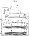
- Fig. 2 is a schematic view illustrating the internal configuration of the printer 30.
- the printer 30 includes a housing unit 41, the conveyance mechanism 38, the printing unit 37, a fixing unit 43, and a discharge tray 45.
- the housing unit 41 is provided in the bottom portion of the printer 30, and includes a plurality (for example, two) of trays T, each of which accommodates sheets W.
- a plurality for example, two
- trays T each of which accommodates sheets W.
- the respective trays T are discriminated, they are sequentially referred to as a first tray T1 and a second tray T2 from the uppermost tray.
- the conveyance mechanism 38 includes a pickup roller 47, a pair of registration rollers 49, 49, a sheet conveyance belt 51, and a reversing mechanism 53.
- the pickup roller 47 picks up the sheets W accommodated in the tray T one by one, and then conveys the sheet W to the registration rollers 49, 49.
- the registration rollers 49, 49 adjust the posture of the conveyed sheet W to deliver onto the sheet conveyance belt 51 at predetermined timing.
- the printing unit 37 forms an image (monochrome image or color image) at a predetermined printing position X on the sheet W conveyed by the sheet conveyance belt 51, based on printing data received from the terminal device 10, for example.
- the sheet W having the image formed thereon is thermally fixed by the fixing unit 43 and then discharged onto the discharge tray 45.
- a path for guiding the sheet W from the tray T to the printing position X, which is indicated by a solid arrow of Fig. 2 is referred to as a printing conveyance path P1 as an example of printing paths.
- the reversing mechanism 53 includes a discharge roller 55, a reverse conveyance path P2 as an example of reverse paths, which is indicated by the dotted-line arrow in Fig. 2 , a flapper 59, and a plurality of reversing conveyance rollers 61.
- a discharge roller 55 a reverse conveyance path P2 as an example of reverse paths, which is indicated by the dotted-line arrow in Fig. 2 .
- a flapper 59 a plurality of reversing conveyance rollers 61.
- the sheet W is conveyed through the flapper 59, the reverse conveyance path P2, the plurality of reversing conveyance rollers 61, and the registration rollers 49, 49 by the reverse rotation of the discharge roller 55, and then delivered onto the tray 51 in a state in which the front and rear surfaces are reversed. Then, an image is printed on the front surface of the sheet W by the printing unit 37, which corresponds to an upper surface of the sheet W when the sheet W is accommodated in the tray T, and the sheet W is discharged onto the discharge tray 45.
- the sheet detection unit 40 includes a plurality of sensors 40A which outputs a detection signal depending on whether or not a sheet W is present at the respective conveyance positions inside the conveyance mechanism 38.
- the CPU 31 consecutively receives a detection signal indicating the presence of the sheet W from the respective sensors 40A for a predetermined time or more or does not receive a detection signal for a predetermined time or more, the CPU 31 determines that jamming (sheet jamming) occurred at the respective positions.
- one or more sensors 40A are provided in the printing conveyance path P1 and the reverse conveyance path P2, respectively. Therefore, the CPU 31 also can determine whether or not jamming occurs in any one of the printing conveyance path P1 and the reverse conveyance path P2.
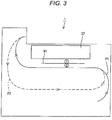
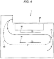
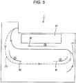
- Figs. 3 to 5 are pattern diagrams explaining methods of the double-side printing processing.
- a number surrounded by a circle means that an image corresponding to the sequence of the number is formed on the surface of sheet W at the side where the number is attached.
- the printer 30 can perform the double-side printing method depending on a plurality of methods.
- the plurality of methods are classified into a reversing method which uses the reversing mechanism 53 and a non-reversing method which does not use the reversing mechanism 53.
- the reversing method is classified depending on a difference in the maximum number of sheets W existing in the conveyance mechanism 38 at the same time.
- the sheets W have an image formed on one surface thereof, and does not have an image formed on the other surface thereof.
- examples of the methods will be described.
- the 21 method is a double-side continuous printing method in which printing on one surface and printing on the other surface for each sheet W1 are continuously performed from the beginning to the end of the printing. For example, when six page images are printed on both surfaces of three sheets W, the printer 30 performs printing in the following sequence:
- the printer 30 while printing is performed on the front surface of a sheet W after the printing is performed on the rear surface of the sheet W, the printer 30 does not perform printing on another sheet W.
- the maximum sheet number is one.
- the 2413 method includes a process in which while printing is performed on the front surface of a sheet W after printing is performed on the rear surface of the sheet W, printing is performed on the rear surface of another sheet W. For example, when six page images are printed on both surfaces of three sheets W, the printer 30 performs printing in the following sequence:
- the maximum sheet number is two.
- the 246135 method includes a process in which while printing is performed on the front surface of a sheet W after printing is performed on the rear surface of the sheet W, printing is performed on the rear surfaces of two other sheets W. For example, when six page images are printed on both surfaces of three sheets W, the printer 30 performs printing in the following sequence:
- the 246135 method as illustrated in Fig. 5 , when the first sheet W1 having the second image printed thereon and the second sheet W2 having the fourth image printed thereon exist in the reverse conveyance path P2, the third sheet W3 exists in the printing conveyance path P1. Accordingly, the maximum sheet number is three.
- the 246135 method will be omitted to simplify the descriptions.
- the manual method one or more sheets W are discharged to the discharge tray 45 without passing through the reverse conveyance path P2, in a state in which only the rear surfaces thereof are printed.
- the discharged sheets W are reset on the tray T by a user such that the rear surfaces (printed surfaces) thereof face upward.
- the front surface of the reset sheets W are printed, and the sheets W are discharged to the discharge tray 45 without passing through the reverse conveyance path P2.
- the maximum sheet number is 1 or 2 which is the number of sheets which can be accommodated in the printing conveyance path P1, but the sheets do not pass through the reverse conveyance path P2.
- the printing system 1 performs printing control processing which will be described below, such that double-side printing processing can be performed in accordance with a method selected automatically from the above-described methods according to jamming occurrence probability of the printer 30.
- printing control processing will be divided into processing at the terminal device 10 and processing at the printer 30.
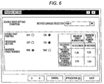
- Fig. 6 is a diagram illustrating a double-side printing setting screen.
- the CPU 11 reads the printer driver from the HDD 14 to selectively display a basic setting screen for setting general printing conditions such as sheet size and image quality, extended function screens, and a support screen on the display unit 16.
- the double-side printing setting screen is one of the extended function screens.
- the double side setting screen includes a tray selection field, a double-side printing field, a reversing method field, and a maximum sheet number field.
- the double-side printing field as a user switches over between ON and OFF buttons, any one of the double-side printing processing and the one side printing processing can be selectively performed. Furthermore, when the one side printing processing is selected, that is, the OFF button is clicked, the other fields may be grayed out so as not to be selected.
- any one of the reversing method and the non-reversing method may be selected. Furthermore, when the non-reversing method is selected, that is, the OFF button is clicked, the maximum sheet number field and the manual method auto-switching field may be grayed out so as not to be selected.
- the user can select a reversing method corresponding to the selected sheet number.
- the number of the tray T (the first tray T1 or the second tray T2) is pull-down displayed so that the user can select a tray.
- the double-side printing setting screen may display jamming information on the methods of the double-side printing processing which can be performed by the printer 30.
- the jamming information includes a required time, an individual jamming occurrence probability, and an individual reversing jamming occurrence probability for each of the methods whereby the maximum sheet numbers are different from each other.
- the required time is the average required time when a reference number (for example, ten) of sheets W are printed.
- the reference number of sheets may be a fixed value, or the number of printed sheets for each printing data. In the latter, a time obtained by multiplying the reference number by a unit required time per sheet W1 for each of the methods may be set to the required time.
- the individual jamming occurrence probability refers to an occurrence probability of jamming (hereinafter, referred to as individual jamming) which occurs in the printer 30 including the printing conveyance path P1 and the reverse conveyance path P2, when the double-side printing processing is performed using each of the methods.
- the individual jamming occurrence probability is calculated by dividing the number of occurrences of individual jamming by the accumulative number of printed sheets W in the printer 30. Especially, it is preferable to use the accumulative number of double-side printed sheets.
- the individual reversing jamming occurrence probability refers to an occurrence probability of jamming (hereinafter, referred to as individual reversing jamming) which occurs only in the reverse conveyance path P2. In this embodiment, the individual reversing jamming occurrence probability is calculated by dividing the number of occurrences of individual reversing jamming by the accumulative number of printed sheets.
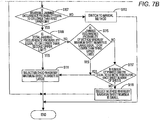
- Fig. 7 is a flow chart showing the double-side printing setting processing.
- the CPU 11 performs the double-side printing setting processing.
- the jamming information is not displayed on the double-side printing setting screen.
- step S101: NO when it is determined that a user selects the one sided printing and then clicks an OK button or application button on the printing setting screen (step S101: NO), the double-side printing setting processing is terminated.
- step S101: YES and step S103: NO the double-side printing setting processing is terminated.
- step S103 when it is determined that a reversing method is selected (step S103: YES), the latest jamming information is received from the printer 30 and then displayed on the double-side printing setting screen (step S105) (refer to Fig. 6 ). Accordingly, the user can check the jamming occurrence probabilities of the respective methods by referring to the displayed jamming information.
- the CPU 11 determines whether or not an average occurrence probability of reversing jamming is equal to or lower than a first upper limit (for example, 5%), by referring to the jamming information (step S107).
- the average occurrence probability of reversing jamming refers to an average of individual reversing jamming occurrence probabilities in the respective reversing methods. Instead of the average occurrence probability of reverse jamming, an occurrence probability of individual reversing jamming in a method predetermined as a default value may be set to a determination target.
- step S107 NO
- the double-side printing processing is performed in accordance with the reversing method, and the method is forcibly switched to the manual method (step S113). Then, the double-side printing setting processing is terminated.
- step S107 when it is determined that the average occurrence probability of reversing jamming is equal to or lower than the first upper limit (step S107: YES), it is determined whether or not the total jamming occurrence probability is equal to or lower than a second upper limit (for example, 1%), by referring to the jamming information (step S109).
- a second upper limit for example, 1%
- An average occurrence probability of total jamming refers to an average of individual jamming occurrence probabilities in the respective reversing methods.
- the occurrence probability of reversing jamming in a method predetermined as a default value for example, a method whereby the maximum sheet number is large
- a default value for example, a method whereby the maximum sheet number is large
- step S109 When it is determined that the total jamming occurrence probability is equal to or lower than the second upper limit (step S109: YES), a method (2413 method) is selected whereby the maximum sheet number is large (step S111), and the double-side printing setting processing is terminated. Furthermore, when the occurrence probability of reversing jamming in the default method is set to a determination target, the default method is selected.
- step S109: NO it is determined whether or not the individual jamming occurrence probability of the method whereby the maximum sheet number is large is equal to or lower than a third upper limit (for example, 2%) (step S115).
- the CPU 11 functions as a determination unit.
- step S115: YES it is considered that there is a low risk of jamming occurrence even though the double-side printing processing is performed in accordance with the method (2413 method) whereby the maximum sheet number is large, and the method is selected whereby the maximum sheet number is large (step S111).
- the double-side printing setting processing is terminated.
- a relative difference in individual jamming occurrence probability between the method whereby the maximum sheet number is large and the method whereby the maximum sheet number is small is less than a reference value (for example, 0.5%), the method may be selected whereby the maximum sheet number is large.
- step S115: NO the method whereby the maximum sheet number is large is selected in preference to high-speed processing rather than jamming avoidance (step S111), when the number of sheets W (corresponding to the page number of printing data) which are printed by the double-side printing processing based on printing data of the currently-set target is equal to or more than a reference sheet number of sheets (for example, 30 sheets) (step S117: YES). Then, the double-side printing setting processing is terminated in preference to high-speed processing rather than jamming avoidance.
- step S117: NO when the number of sheets W printed by the double-side printing processing is less than the reference number (step S117: NO), a method (21 method) whereby the maximum sheet number is small is selected in preference to jamming avoidance (step S119), and the double-side printing setting processing is terminated.
- the CPU 11 transmits printing data and the variety of printing setting information set on the printing setting screen to the printer 30.
- the printing data includes image data to be printed
- the variety of printing setting information includes the method of the double-side printing processing.
- the CPU 31 of the printer 30 controls the printing unit 37 and the conveyance mechanism 38 based on the printing data, and starts the double-side printing processing of the method depending on the printing setting information. At this time, the CPU 31 functions as the control unit. Furthermore, when the double-side printing processing starts, the CPU 31 starts jamming monitoring processing.
- Fig. 8 is a flow chart showing jamming monitoring processing.
- the CPU 31 monitors whether jamming occurred or not, based on detection signals from the respective sensors 40A (step S201). When it is determined that jamming occurred (step S201 : YES), the CPU stops the double-side printing processing (step S203), and updates the jamming information table (step S205).
- Fig. 9 is a diagram showing an example of the contents of the jamming information table.
- the jamming information table is original data for generating the jamming information transmitted to the terminal device 10, and is stored in the HDD 34.
- the CPU 31 calculates the total jamming occurrence probability whenever jamming occurs, and updates the jamming information table.
- step S207 it is determined whether the jamming was removed or not. For example, when detection signals indicating no sheet exists are received from all of the sensors 40A, it is determined that the jamming was removed.
- step S207 the jamming information the same as shown in Fig. 6 , for example, is displayed on the display unit 36 (step S209).
- the user can determine whether or not to continue the method which is being performed.
- step S211 NO
- step S211 NO
- step S211 YES
- step S211 YES
- step S215 the double-side printing processing is resumed as the changed method
- step S215 the operation returns to step S201.
- the CPU 31 functions as the changing unit.
- the double-side printing processing is performed in accordance with a method whereby the maximum sheet number of sheets existing in the conveyance mechanism 38 at the same time is small, compared with when the jamming occurrence probability is low. Accordingly, it is possible to perform the double-side printing processing in accordance with the method depending on the jamming occurrence state of the printer 30. For example, when the occurrence probability is relatively low, the printing can be performed at a high speed by performing the double-side printing processing in accordance with the method whereby the maximum sheet number is large. Meanwhile, when the occurrence probability is relatively high, the double-side printing processing may be performed in accordance with the method whereby the maximum sheet number is small. In this case, it is possible to reduce the effort of a sheet removing operation which would be performed if jamming occurs.
- the non-reversing method may be selected without using the reverse conveyance path P2, which makes it possible to reduce the jamming occurrence.
- the jamming management processing may be performed to change the method of the double-side printing processing at this point of time. Furthermore, when the number of sheets W to be double-side printed is relatively large, the method whereby the maximum sheet number is large may be selected to perform the double-side printing processing at a high speed.
Landscapes
- Engineering & Computer Science (AREA)
- Physics & Mathematics (AREA)
- General Physics & Mathematics (AREA)
- Theoretical Computer Science (AREA)
- Human Computer Interaction (AREA)
- General Engineering & Computer Science (AREA)
- Accessory Devices And Overall Control Thereof (AREA)
- Control Or Security For Electrophotography (AREA)
- Conveyance By Endless Belt Conveyors (AREA)
- Paper Feeding For Electrophotography (AREA)
- Separation, Sorting, Adjustment, Or Bending Of Sheets To Be Conveyed (AREA)
Claims (6)
- Drucksystem, aufweisend:eine Druckeinheit (37), die ein Drucken auf einem Blatt durchführt;einen Transportmechanismus (38) mit einem Druckweg (P1), auf dem ein Blatt zu einer Druckposition der Druckeinheit (37) geführt wird, und mit einem Wendeweg (P2), auf dem das Blatt, das die Druckposition durchläuft, gewendet wird und das Blatt erneut zur Druckposition geführt wird;eine Steuereinheit (31), die eine doppelseitige Druckverarbeitung abhängig von einer Mehrzahl von Verfahren durchführt, bei denen die Höchstzahlen der Blätter, die gleichzeitig im Transportmechanismus (38) vorhanden sind, jeweils verschieden sind, wobei die Mehrzahl von Verfahren ein erstes Verfahren und ein zweites Verfahren umfasst, wobei die Höchstzahl der Blätter, die gleichzeitig im Transportmechanismus (38) vorhanden sind, im ersten Verfahren größer ist als im zweiten Verfahren;eine Erfassungseinheit (40), die einen Papierstau erfasst; undeine Bestimmungseinheit, die eine Wahrscheinlichkeit dafür, dass ein Papierstau im Transportmechanismus (38) auftreten wird, auf Basis eines Erfassungsergebnisses der Erfassungseinheit (40) bestimmt,dadurch gekennzeichnet, dass die Steuereinheit (31) das erste Verfahren auswählt, wenn die Bestimmungseinheit bestimmt, dass die Wahrscheinlichkeit dafür, dass ein Papierstau auftreten wird, höchstens so hoch ist wie ein oberer Grenzwert, unddann, wenn die Bestimmungseinheit bestimmt, dass die Wahrscheinlichkeit dafür, dass ein Papierstau auftreten wird, höher ist als der obere Grenzwert, die Steuereinheit (31) das zweite Verfahren auswählt, falls eine relative Differenz einer individuellen Stauereigniswahrscheinlichkeit zwischen dem ersten Verfahren und dem zweiten Verfahren größer ist als ein Bezugswert, und die (31) Steuereinheit das erste Verfahren auswählt, wenn die relative Differenz höchstens so groß ist wie der Bezugswert, wobei die individuelle Stauereigniswahrscheinlichkeit eine Wahrscheinlichkeit für ein Stauereignis bezeichnet, dass im Drucksystem eintritt, wenn die doppelseitige Druckverarbeitung unter Verwendung von jedem von der Mehrzahl von Verfahren jeweils durchgeführt wird, unddie Steuereinheit (31) die doppelseitige Druckverarbeitung gemäß dem ausgewählten Verfahren durchführt.
- Drucksystem nach Anspruch 1, wobei
die Bestimmungseinheit eine Höhe der Stauereigniswahrscheinlichkeit im Wendeweg (P2) bestimmt, und
die Steuereinheit (31) ein Verfahren ohne Wenden auswählt, bei dem der Wendeweg (P2) nicht verwendet wird, und die doppelseitige Druckverarbeitung gemäß dem ausgewählten Verfahren ohne Wenden durchführt, wenn die Bestimmungseinheit bestimmt, dass die Stauereigniswahrscheinlichkeit höher ist als ein anderer oberer Grenzwert. - Drucksystem nach Anspruch 1 oder 2, ferner eine Änderungseinheit aufweisend, die das Verfahren der doppelseitigen Druckverarbeitung ändert, während die doppelseitige Druckverarbeitung, die durch die Druckeinheit durchgeführt wird, im Gange ist.
- Drucksystem nach einem der Ansprüche 1 bis 3, wobei die Steuereinheit (31) selbst dann, wenn auf Basis des Bestimmungsergebnisses der Bestimmungseinheit das zweite Verfahren ausgewählt werden sollte, das erste Verfahren auswählt, wenn die Zahl der Blätter, die doppelseitig bedruckt werden sollen, mindestens so groß ist wie eine Bezugs-Blattzahl.
- Druckvorrichtung, aufweisend:eine Druckeinheit (37), die ein Drucken auf einem Blatt durchführt;einen Transportmechanismus (38) mit einem Druckweg (P1), auf dem ein Blatt zu einer Druckposition der Druckeinheit (37) geführt wird, und einen Wendemechanismus (53) mit einem Wendeweg (P2) zum Wenden des Blattes, das die Druckposition durchläuft, und zum erneuten Führen des Blattes zur Druckposition;eine Steuereinheit (31), welche die Druckeinheit (37) und den Wendemechanismus (53) so steuert, dass diese eine doppelseitige Druckverarbeitung abhängig von einer Mehrzahl von Verfahren durchführen, bei denen Höchstzahlen von Blättern, die gleichzeitig im Wendemechanismus (53) vorhanden sind, voneinander verschieden sind, wobei die Mehrzahl von Verfahren ein erstes Verfahren und ein zweites Verfahren umfasst, wobei die Höchstzahl der Blätter, die gleichzeitig im Transportmechanismus (38) vorhanden sind, im ersten Verfahren größer ist als im zweiten Verfahren;eine Erfassungseinheit (40), die einen Papierstau erfasst, undeine Bestimmungseinheit, die eine Wahrscheinlichkeit für ein Papierstauereignis im Transportmechanismus (38) auf Basis des Erfassungsergebnisses der Erfassungseinheit (40) bestimmt,dadurch gekennzeichnet, dass die Steuereinheit (31) das erste Verfahren auswählt, wenn die Bestimmungseinheit bestimmt, dass die Ereigniswahrscheinlichkeit höchstens so hoch ist wie ein oberer Grenzwert, unddann, wenn die Bestimmungseinheit bestimmt, dass die Stauereigniswahrscheinlichkeit höher ist als der obere Grenzwert, die Steuereinheit (31) das zweite Verfahren auswählt, falls eine relative Differenz einer individuellen Stauereigniswahrscheinlichkeit zwischen dem ersten Verfahren und dem zweiten Verfahren größer ist als ein Bezugswert, und die Steuereinheit (31) das erste Verfahren auswählt, wenn die relative Differenz höchstens so groß ist wie der Bezugswert,wobei die individuelle Stauereigniswahrscheinlichkeit eine Wahrscheinlichkeit für ein Papierstauereignis bezeichnet, das im Drucksystem eintritt, wenn die doppelseitige Druckverarbeitung unter Verwendung von jedem von der Mehrzahl von Verfahren jeweils durchgeführt wird, undwobei die Steuereinheit (31) die doppelseitige Druckverarbeitung gemäß dem ausgewählten Verfahren durchführt.
- Druckertreiber einer Druckvorrichtung, die mit einen Transportmechanismus (38) aufweist und die eine doppelseitige Druckverarbeitung abhängig von einer Mehrzahl von Verfahren durchführt, bei denen sich Höchstzahlen von Blättern, die gleichzeitig im Transportmechanismus (38) vorhanden sind, voneinander unterscheiden, wobei die Mehrzahl von Verfahren ein erstes Verfahren und ein zweites Verfahren umfasst, wobei die Höchstzahl der Blätter, die gleichzeitig im Transportmechanismus (38) vorhanden sind, im ersten Verfahren größer ist als im zweiten Verfahren, und der Druckertreiber bewirkt, dass eine Informationsverarbeitungsvorrichtung, die mit der Druckvorrichtung in Kommunikationsverbindung steht, Folgendes durchführt:Bestimmen, wie hoch eine Wahrscheinlichkeit für ein Papierstauereignis im Transportmechanismus (38) ist, auf Basis eines Erfassungsergebnisses, das von einer Erfassungseinheit (40) erhalten wird, die einen Papierstau erfasst,dadurch gekennzeichnet, dass das erste Verfahren ausgewählt wird, wenn bestimmt wird, dass die Stauereigniswahrscheinlichkeit höchstens so groß ist wie ein oberer Grenzwert;dann, wenn bestimmt wird, dass die Stauereigniswahrscheinlichkeit höher ist als der obere Grenzwert, das zweite Verfahren ausgewählt wird, falls eine relative Differenz einer individuellen Stauereigniswahrscheinlichkeit zwischen dem ersten Verfahren und dem zweiten Verfahren größer ist als ein Bezugswert, und das erste Verfahren ausgewählt wird, wenn die relative Differenz höchstens so groß ist wie der Bezugswert, undder Druckvorrichtung befohlen wird, die doppelseitige Druckverarbeitung gemäß dem ausgewählten Verfahren durchzuführen.
Applications Claiming Priority (1)
| Application Number | Priority Date | Filing Date | Title |
|---|---|---|---|
| JP2009111607A JP4863096B2 (ja) | 2009-04-30 | 2009-04-30 | 印刷システム、印刷装置及びプリンタドライバ |
Publications (3)
| Publication Number | Publication Date |
|---|---|
| EP2246779A2 EP2246779A2 (de) | 2010-11-03 |
| EP2246779A3 EP2246779A3 (de) | 2012-04-25 |
| EP2246779B1 true EP2246779B1 (de) | 2018-05-09 |
Family
ID=42197737
Family Applications (1)
| Application Number | Title | Priority Date | Filing Date |
|---|---|---|---|
| EP10003226.7A Not-in-force EP2246779B1 (de) | 2009-04-30 | 2010-03-25 | Drucksystem, Druckgerät und Druckertreiber |
Country Status (4)
| Country | Link |
|---|---|
| US (1) | US9031423B2 (de) |
| EP (1) | EP2246779B1 (de) |
| JP (1) | JP4863096B2 (de) |
| CN (1) | CN101875265B (de) |
Families Citing this family (15)
| Publication number | Priority date | Publication date | Assignee | Title |
|---|---|---|---|---|
| JP4894883B2 (ja) * | 2009-04-30 | 2012-03-14 | ブラザー工業株式会社 | 印刷システム、印刷装置及びプリンタドライバ |
| JP4863096B2 (ja) | 2009-04-30 | 2012-01-25 | ブラザー工業株式会社 | 印刷システム、印刷装置及びプリンタドライバ |
| JP5278459B2 (ja) * | 2011-01-31 | 2013-09-04 | ブラザー工業株式会社 | 印刷装置及び両面印刷制御プログラム |
| JP6129785B2 (ja) * | 2013-09-30 | 2017-05-17 | 京セラドキュメントソリューションズ株式会社 | 画像形成装置およびプリンタードライバー |
| JP6366370B2 (ja) * | 2014-06-04 | 2018-08-01 | キヤノン株式会社 | 記録装置、記録装置の制御方法、プログラムおよび記憶媒体 |
| US9912832B2 (en) | 2014-08-14 | 2018-03-06 | Kabushiki Kaisha Toshiba | Image forming apparatus and control method of the same |
| JP6939146B2 (ja) * | 2017-06-29 | 2021-09-22 | ブラザー工業株式会社 | 画像形成装置およびシート搬送方法 |
| JP2019072893A (ja) * | 2017-10-13 | 2019-05-16 | 京セラドキュメントソリューションズ株式会社 | 画像形成装置 |
| US10998514B2 (en) | 2017-12-01 | 2021-05-04 | Samsung Electronics Co., Ltd. | Photoelectric devices and image sensors and electronic devices |
| CN108001049A (zh) * | 2017-12-28 | 2018-05-08 | 北京摩数教育科技有限公司 | 一种改进的打印机 |
| JP2020071442A (ja) * | 2018-11-02 | 2020-05-07 | コニカミノルタ株式会社 | 画像形成装置、搬送枚数調整方法、およびコンピュータプログラム |
| CN110228723A (zh) * | 2019-07-10 | 2019-09-13 | 威海新北洋技术服务有限公司 | 出纸装置及打印机 |
| JP7422559B2 (ja) * | 2020-02-27 | 2024-01-26 | キヤノン株式会社 | 画像形成装置 |
| CN112659762B (zh) * | 2020-12-30 | 2025-06-24 | 宁波得力科贝技术有限公司 | 一种双面打印机 |
| CN116405605B (zh) * | 2023-03-29 | 2025-08-19 | 珠海奔图电子有限公司 | 一种卡纸处理方法及系统、图像形成设备和存储介质 |
Citations (1)
| Publication number | Priority date | Publication date | Assignee | Title |
|---|---|---|---|---|
| JP2005041229A (ja) * | 2004-09-27 | 2005-02-17 | Fujitsu Ltd | 画像形成装置 |
Family Cites Families (24)
| Publication number | Priority date | Publication date | Assignee | Title |
|---|---|---|---|---|
| US5557367A (en) * | 1995-03-27 | 1996-09-17 | Xerox Corporation | Method and apparatus for optimizing scheduling in imaging devices |
| JP3725203B2 (ja) * | 1995-06-05 | 2005-12-07 | 富士通株式会社 | 画像形成装置 |
| JPH11284818A (ja) | 1998-03-27 | 1999-10-15 | Fuji Xerox Co Ltd | 画像処理装置 |
| JP3768785B2 (ja) | 2000-07-19 | 2006-04-19 | キヤノン株式会社 | 画像形成装置および記憶媒体 |
| JP2003098910A (ja) | 2001-09-25 | 2003-04-04 | Konica Corp | 残時間報知機能付き画像形成装置及び残時間算出方法 |
| JP2003274081A (ja) | 2002-03-13 | 2003-09-26 | Ricoh Co Ltd | 画像形成装置、および画像形成方法 |
| US6778787B2 (en) | 2002-04-05 | 2004-08-17 | Canon Kabushiki Kaisha | Image forming apparatus with control to divert sheet to usable path |
| JP2004164618A (ja) | 2002-10-14 | 2004-06-10 | Oce Technol Bv | 携帯端末における選択メカニズム |
| JP2005221821A (ja) | 2004-02-06 | 2005-08-18 | Fuji Xerox Co Ltd | 画像形成装置 |
| JP4538845B2 (ja) | 2004-04-21 | 2010-09-08 | 富士ゼロックス株式会社 | 故障診断方法および故障診断装置、画像形成装置、並びにプログラムおよび記憶媒体 |
| JP4468154B2 (ja) | 2004-12-22 | 2010-05-26 | シャープ株式会社 | 画像形成装置および手差し給紙装置 |
| JP4617981B2 (ja) | 2005-04-18 | 2011-01-26 | コニカミノルタビジネステクノロジーズ株式会社 | 画像形成システム |
| JP2007030476A (ja) | 2005-07-29 | 2007-02-08 | Canon Inc | 印刷システム |
| JP2007058027A (ja) | 2005-08-26 | 2007-03-08 | Konica Minolta Business Technologies Inc | 画像形成方法および画像形成装置 |
| EP1857921A3 (de) | 2006-05-12 | 2010-06-09 | Ricoh Company, Ltd. | Verwaltung von Aufzeichnungsblattinformationen |
| JP2008090219A (ja) | 2006-10-05 | 2008-04-17 | Seiko Epson Corp | 画像形成装置、および画像形成装置の制御方法 |
| JP2009006484A (ja) | 2007-06-26 | 2009-01-15 | Kyocera Mita Corp | 画像形成装置 |
| JP5366428B2 (ja) * | 2007-07-23 | 2013-12-11 | 理想科学工業株式会社 | 両面印刷装置 |
| WO2009014033A1 (ja) | 2007-07-23 | 2009-01-29 | Riso Kagaku Corporation | 両面印刷装置 |
| JP2009075153A (ja) | 2007-09-18 | 2009-04-09 | Ricoh Co Ltd | 画像形成装置 |
| JP5081638B2 (ja) | 2008-01-11 | 2012-11-28 | 理想科学工業株式会社 | 印刷装置 |
| JP4575482B2 (ja) | 2008-09-05 | 2010-11-04 | 富士通株式会社 | 画像形成装置 |
| JP4863096B2 (ja) | 2009-04-30 | 2012-01-25 | ブラザー工業株式会社 | 印刷システム、印刷装置及びプリンタドライバ |
| JP2011004267A (ja) | 2009-06-19 | 2011-01-06 | Konica Minolta Business Technologies Inc | 画像形成装置、画像形成装置において実行される故障予測方法、及び画像形成装置の制御プログラム |
-
2009
- 2009-04-30 JP JP2009111607A patent/JP4863096B2/ja active Active
-
2010
- 2010-03-25 EP EP10003226.7A patent/EP2246779B1/de not_active Not-in-force
- 2010-03-26 US US12/732,867 patent/US9031423B2/en active Active
- 2010-03-30 CN CN201010156867.8A patent/CN101875265B/zh active Active
Patent Citations (1)
| Publication number | Priority date | Publication date | Assignee | Title |
|---|---|---|---|---|
| JP2005041229A (ja) * | 2004-09-27 | 2005-02-17 | Fujitsu Ltd | 画像形成装置 |
Also Published As
| Publication number | Publication date |
|---|---|
| JP4863096B2 (ja) | 2012-01-25 |
| EP2246779A3 (de) | 2012-04-25 |
| US9031423B2 (en) | 2015-05-12 |
| JP2010262085A (ja) | 2010-11-18 |
| US20100276870A1 (en) | 2010-11-04 |
| EP2246779A2 (de) | 2010-11-03 |
| CN101875265A (zh) | 2010-11-03 |
| CN101875265B (zh) | 2014-07-30 |
Similar Documents
| Publication | Publication Date | Title |
|---|---|---|
| US9031423B2 (en) | Printing system, printing device, and printer driver | |
| EP2246780B1 (de) | Drucksystem, Druckvorrichtung und Druckertreiber | |
| JP4798470B2 (ja) | 印刷装置 | |
| CN101086636B (zh) | 图像形成设备和输送故障判断方法 | |
| US20070014614A1 (en) | Image forming apparatus and program for outputting error information of image forming apparatus | |
| JP2017056668A (ja) | 画像形成装置およびその制御方法 | |
| JP4575482B2 (ja) | 画像形成装置 | |
| JP2011201082A (ja) | 印刷制御装置、印刷システム、及びプログラム | |
| US6246926B1 (en) | Sheet sorting apparatus and sheet sorting method | |
| US20120013946A1 (en) | Printing system, printing method, and recording medium | |
| US5913015A (en) | Image forming system including sorter unit | |
| JP5559498B2 (ja) | 画像形成装置 | |
| JP2008262103A (ja) | 印刷装置の制御装置、印刷システム、および印刷装置の制御プログラム | |
| JP2013077143A (ja) | 画像形成管理装置、画像形成管理システムおよび画像形成管理プログラム | |
| US8831458B2 (en) | Image forming apparatus | |
| JP2011212946A (ja) | 画像形成装置 | |
| EP4620879A1 (de) | Blattzuführvorrichtung und bilderzeugungsvorrichtung damit | |
| JP2003145858A (ja) | 記録装置 | |
| JP2010222097A (ja) | 記録媒体供給装置及び画像形成装置 | |
| US20210034309A1 (en) | Image forming apparatus | |
| KR20040009170A (ko) | 이면지 제한 기능을 구비한 양면인쇄장치 및 그 제어방법 | |
| JP2005215593A (ja) | 画像形成装置 | |
| JP2021162766A (ja) | 画像形成装置 | |
| JP2010226295A (ja) | 画像形成装置 | |
| JP2008290305A (ja) | 画像形成装置 |
Legal Events
| Date | Code | Title | Description |
|---|---|---|---|
| PUAI | Public reference made under article 153(3) epc to a published international application that has entered the european phase |
Free format text: ORIGINAL CODE: 0009012 |
|
| AK | Designated contracting states |
Kind code of ref document: A2 Designated state(s): AT BE BG CH CY CZ DE DK EE ES FI FR GB GR HR HU IE IS IT LI LT LU LV MC MK MT NL NO PL PT RO SE SI SK SM TR |
|
| AX | Request for extension of the european patent |
Extension state: AL BA ME RS |
|
| PUAL | Search report despatched |
Free format text: ORIGINAL CODE: 0009013 |
|
| AK | Designated contracting states |
Kind code of ref document: A3 Designated state(s): AT BE BG CH CY CZ DE DK EE ES FI FR GB GR HR HU IE IS IT LI LT LU LV MC MK MT NL NO PL PT RO SE SI SK SM TR |
|
| AX | Request for extension of the european patent |
Extension state: AL BA ME RS |
|
| RIC1 | Information provided on ipc code assigned before grant |
Ipc: G06F 3/12 20060101AFI20120320BHEP |
|
| 17P | Request for examination filed |
Effective date: 20121025 |
|
| 17Q | First examination report despatched |
Effective date: 20141014 |
|
| STAA | Information on the status of an ep patent application or granted ep patent |
Free format text: STATUS: EXAMINATION IS IN PROGRESS |
|
| RIC1 | Information provided on ipc code assigned before grant |
Ipc: B41J 3/60 20060101ALI20171019BHEP Ipc: B41J 13/00 20060101ALI20171019BHEP Ipc: G06F 3/12 20060101AFI20171019BHEP Ipc: G03G 15/23 20060101ALI20171019BHEP Ipc: G03G 15/00 20060101ALI20171019BHEP |
|
| GRAP | Despatch of communication of intention to grant a patent |
Free format text: ORIGINAL CODE: EPIDOSNIGR1 |
|
| STAA | Information on the status of an ep patent application or granted ep patent |
Free format text: STATUS: GRANT OF PATENT IS INTENDED |
|
| INTG | Intention to grant announced |
Effective date: 20171128 |
|
| GRAS | Grant fee paid |
Free format text: ORIGINAL CODE: EPIDOSNIGR3 |
|
| GRAA | (expected) grant |
Free format text: ORIGINAL CODE: 0009210 |
|
| STAA | Information on the status of an ep patent application or granted ep patent |
Free format text: STATUS: THE PATENT HAS BEEN GRANTED |
|
| AK | Designated contracting states |
Kind code of ref document: B1 Designated state(s): AT BE BG CH CY CZ DE DK EE ES FI FR GB GR HR HU IE IS IT LI LT LU LV MC MK MT NL NO PL PT RO SE SI SK SM TR |
|
| REG | Reference to a national code |
Ref country code: GB Ref legal event code: FG4D |
|
| RIN1 | Information on inventor provided before grant (corrected) |
Inventor name: YAMADA, AKIHIRO |
|
| REG | Reference to a national code |
Ref country code: CH Ref legal event code: EP Ref country code: AT Ref legal event code: REF Ref document number: 998163 Country of ref document: AT Kind code of ref document: T Effective date: 20180515 |
|
| REG | Reference to a national code |
Ref country code: IE Ref legal event code: FG4D |
|
| REG | Reference to a national code |
Ref country code: DE Ref legal event code: R096 Ref document number: 602010050455 Country of ref document: DE |
|
| REG | Reference to a national code |
Ref country code: NL Ref legal event code: MP Effective date: 20180509 |
|
| REG | Reference to a national code |
Ref country code: LT Ref legal event code: MG4D |
|
| PG25 | Lapsed in a contracting state [announced via postgrant information from national office to epo] |
Ref country code: LT Free format text: LAPSE BECAUSE OF FAILURE TO SUBMIT A TRANSLATION OF THE DESCRIPTION OR TO PAY THE FEE WITHIN THE PRESCRIBED TIME-LIMIT Effective date: 20180509 Ref country code: SE Free format text: LAPSE BECAUSE OF FAILURE TO SUBMIT A TRANSLATION OF THE DESCRIPTION OR TO PAY THE FEE WITHIN THE PRESCRIBED TIME-LIMIT Effective date: 20180509 Ref country code: NO Free format text: LAPSE BECAUSE OF FAILURE TO SUBMIT A TRANSLATION OF THE DESCRIPTION OR TO PAY THE FEE WITHIN THE PRESCRIBED TIME-LIMIT Effective date: 20180809 Ref country code: FI Free format text: LAPSE BECAUSE OF FAILURE TO SUBMIT A TRANSLATION OF THE DESCRIPTION OR TO PAY THE FEE WITHIN THE PRESCRIBED TIME-LIMIT Effective date: 20180509 Ref country code: BG Free format text: LAPSE BECAUSE OF FAILURE TO SUBMIT A TRANSLATION OF THE DESCRIPTION OR TO PAY THE FEE WITHIN THE PRESCRIBED TIME-LIMIT Effective date: 20180809 Ref country code: ES Free format text: LAPSE BECAUSE OF FAILURE TO SUBMIT A TRANSLATION OF THE DESCRIPTION OR TO PAY THE FEE WITHIN THE PRESCRIBED TIME-LIMIT Effective date: 20180509 |
|
| PG25 | Lapsed in a contracting state [announced via postgrant information from national office to epo] |
Ref country code: GR Free format text: LAPSE BECAUSE OF FAILURE TO SUBMIT A TRANSLATION OF THE DESCRIPTION OR TO PAY THE FEE WITHIN THE PRESCRIBED TIME-LIMIT Effective date: 20180810 Ref country code: LV Free format text: LAPSE BECAUSE OF FAILURE TO SUBMIT A TRANSLATION OF THE DESCRIPTION OR TO PAY THE FEE WITHIN THE PRESCRIBED TIME-LIMIT Effective date: 20180509 Ref country code: NL Free format text: LAPSE BECAUSE OF FAILURE TO SUBMIT A TRANSLATION OF THE DESCRIPTION OR TO PAY THE FEE WITHIN THE PRESCRIBED TIME-LIMIT Effective date: 20180509 Ref country code: HR Free format text: LAPSE BECAUSE OF FAILURE TO SUBMIT A TRANSLATION OF THE DESCRIPTION OR TO PAY THE FEE WITHIN THE PRESCRIBED TIME-LIMIT Effective date: 20180509 |
|
| REG | Reference to a national code |
Ref country code: AT Ref legal event code: MK05 Ref document number: 998163 Country of ref document: AT Kind code of ref document: T Effective date: 20180509 |
|
| PG25 | Lapsed in a contracting state [announced via postgrant information from national office to epo] |
Ref country code: DK Free format text: LAPSE BECAUSE OF FAILURE TO SUBMIT A TRANSLATION OF THE DESCRIPTION OR TO PAY THE FEE WITHIN THE PRESCRIBED TIME-LIMIT Effective date: 20180509 Ref country code: AT Free format text: LAPSE BECAUSE OF FAILURE TO SUBMIT A TRANSLATION OF THE DESCRIPTION OR TO PAY THE FEE WITHIN THE PRESCRIBED TIME-LIMIT Effective date: 20180509 Ref country code: PL Free format text: LAPSE BECAUSE OF FAILURE TO SUBMIT A TRANSLATION OF THE DESCRIPTION OR TO PAY THE FEE WITHIN THE PRESCRIBED TIME-LIMIT Effective date: 20180509 Ref country code: EE Free format text: LAPSE BECAUSE OF FAILURE TO SUBMIT A TRANSLATION OF THE DESCRIPTION OR TO PAY THE FEE WITHIN THE PRESCRIBED TIME-LIMIT Effective date: 20180509 Ref country code: CZ Free format text: LAPSE BECAUSE OF FAILURE TO SUBMIT A TRANSLATION OF THE DESCRIPTION OR TO PAY THE FEE WITHIN THE PRESCRIBED TIME-LIMIT Effective date: 20180509 Ref country code: RO Free format text: LAPSE BECAUSE OF FAILURE TO SUBMIT A TRANSLATION OF THE DESCRIPTION OR TO PAY THE FEE WITHIN THE PRESCRIBED TIME-LIMIT Effective date: 20180509 Ref country code: SK Free format text: LAPSE BECAUSE OF FAILURE TO SUBMIT A TRANSLATION OF THE DESCRIPTION OR TO PAY THE FEE WITHIN THE PRESCRIBED TIME-LIMIT Effective date: 20180509 |
|
| REG | Reference to a national code |
Ref country code: DE Ref legal event code: R097 Ref document number: 602010050455 Country of ref document: DE |
|
| PG25 | Lapsed in a contracting state [announced via postgrant information from national office to epo] |
Ref country code: IT Free format text: LAPSE BECAUSE OF FAILURE TO SUBMIT A TRANSLATION OF THE DESCRIPTION OR TO PAY THE FEE WITHIN THE PRESCRIBED TIME-LIMIT Effective date: 20180509 Ref country code: SM Free format text: LAPSE BECAUSE OF FAILURE TO SUBMIT A TRANSLATION OF THE DESCRIPTION OR TO PAY THE FEE WITHIN THE PRESCRIBED TIME-LIMIT Effective date: 20180509 |
|
| PLBE | No opposition filed within time limit |
Free format text: ORIGINAL CODE: 0009261 |
|
| STAA | Information on the status of an ep patent application or granted ep patent |
Free format text: STATUS: NO OPPOSITION FILED WITHIN TIME LIMIT |
|
| 26N | No opposition filed |
Effective date: 20190212 |
|
| PG25 | Lapsed in a contracting state [announced via postgrant information from national office to epo] |
Ref country code: SI Free format text: LAPSE BECAUSE OF FAILURE TO SUBMIT A TRANSLATION OF THE DESCRIPTION OR TO PAY THE FEE WITHIN THE PRESCRIBED TIME-LIMIT Effective date: 20180509 |
|
| PG25 | Lapsed in a contracting state [announced via postgrant information from national office to epo] |
Ref country code: MC Free format text: LAPSE BECAUSE OF FAILURE TO SUBMIT A TRANSLATION OF THE DESCRIPTION OR TO PAY THE FEE WITHIN THE PRESCRIBED TIME-LIMIT Effective date: 20180509 |
|
| REG | Reference to a national code |
Ref country code: CH Ref legal event code: PL |
|
| GBPC | Gb: european patent ceased through non-payment of renewal fee |
Effective date: 20190325 |
|
| PG25 | Lapsed in a contracting state [announced via postgrant information from national office to epo] |
Ref country code: LU Free format text: LAPSE BECAUSE OF NON-PAYMENT OF DUE FEES Effective date: 20190325 |
|
| REG | Reference to a national code |
Ref country code: BE Ref legal event code: MM Effective date: 20190331 |
|
| PG25 | Lapsed in a contracting state [announced via postgrant information from national office to epo] |
Ref country code: LI Free format text: LAPSE BECAUSE OF NON-PAYMENT OF DUE FEES Effective date: 20190331 Ref country code: CH Free format text: LAPSE BECAUSE OF NON-PAYMENT OF DUE FEES Effective date: 20190331 Ref country code: IE Free format text: LAPSE BECAUSE OF NON-PAYMENT OF DUE FEES Effective date: 20190325 Ref country code: GB Free format text: LAPSE BECAUSE OF NON-PAYMENT OF DUE FEES Effective date: 20190325 |
|
| PG25 | Lapsed in a contracting state [announced via postgrant information from national office to epo] |
Ref country code: FR Free format text: LAPSE BECAUSE OF NON-PAYMENT OF DUE FEES Effective date: 20190331 Ref country code: BE Free format text: LAPSE BECAUSE OF NON-PAYMENT OF DUE FEES Effective date: 20190331 |
|
| PG25 | Lapsed in a contracting state [announced via postgrant information from national office to epo] |
Ref country code: TR Free format text: LAPSE BECAUSE OF FAILURE TO SUBMIT A TRANSLATION OF THE DESCRIPTION OR TO PAY THE FEE WITHIN THE PRESCRIBED TIME-LIMIT Effective date: 20180509 |
|
| PG25 | Lapsed in a contracting state [announced via postgrant information from national office to epo] |
Ref country code: PT Free format text: LAPSE BECAUSE OF FAILURE TO SUBMIT A TRANSLATION OF THE DESCRIPTION OR TO PAY THE FEE WITHIN THE PRESCRIBED TIME-LIMIT Effective date: 20180910 Ref country code: MT Free format text: LAPSE BECAUSE OF NON-PAYMENT OF DUE FEES Effective date: 20190325 |
|
| PG25 | Lapsed in a contracting state [announced via postgrant information from national office to epo] |
Ref country code: CY Free format text: LAPSE BECAUSE OF FAILURE TO SUBMIT A TRANSLATION OF THE DESCRIPTION OR TO PAY THE FEE WITHIN THE PRESCRIBED TIME-LIMIT Effective date: 20180509 |
|
| PG25 | Lapsed in a contracting state [announced via postgrant information from national office to epo] |
Ref country code: IS Free format text: LAPSE BECAUSE OF FAILURE TO SUBMIT A TRANSLATION OF THE DESCRIPTION OR TO PAY THE FEE WITHIN THE PRESCRIBED TIME-LIMIT Effective date: 20180909 |
|
| PG25 | Lapsed in a contracting state [announced via postgrant information from national office to epo] |
Ref country code: HU Free format text: LAPSE BECAUSE OF FAILURE TO SUBMIT A TRANSLATION OF THE DESCRIPTION OR TO PAY THE FEE WITHIN THE PRESCRIBED TIME-LIMIT; INVALID AB INITIO Effective date: 20100325 |
|
| PG25 | Lapsed in a contracting state [announced via postgrant information from national office to epo] |
Ref country code: MK Free format text: LAPSE BECAUSE OF FAILURE TO SUBMIT A TRANSLATION OF THE DESCRIPTION OR TO PAY THE FEE WITHIN THE PRESCRIBED TIME-LIMIT Effective date: 20180509 |
|
| PGFP | Annual fee paid to national office [announced via postgrant information from national office to epo] |
Ref country code: DE Payment date: 20240130 Year of fee payment: 15 |
|
| REG | Reference to a national code |
Ref country code: DE Ref legal event code: R119 Ref document number: 602010050455 Country of ref document: DE |
|
| PG25 | Lapsed in a contracting state [announced via postgrant information from national office to epo] |
Ref country code: DE Free format text: LAPSE BECAUSE OF NON-PAYMENT OF DUE FEES Effective date: 20251001 |