EP2241523B1 - Förderkörper und fördervorrichtung - Google Patents
Förderkörper und fördervorrichtung Download PDFInfo
- Publication number
- EP2241523B1 EP2241523B1 EP08870335.0A EP08870335A EP2241523B1 EP 2241523 B1 EP2241523 B1 EP 2241523B1 EP 08870335 A EP08870335 A EP 08870335A EP 2241523 B1 EP2241523 B1 EP 2241523B1
- Authority
- EP
- European Patent Office
- Prior art keywords
- conveying
- drive
- rotation shaft
- conveyance object
- conveying member
- Prior art date
- Legal status (The legal status is an assumption and is not a legal conclusion. Google has not performed a legal analysis and makes no representation as to the accuracy of the status listed.)
- Not-in-force
Links
Images


Classifications
-
- B—PERFORMING OPERATIONS; TRANSPORTING
- B65—CONVEYING; PACKING; STORING; HANDLING THIN OR FILAMENTARY MATERIAL
- B65H—HANDLING THIN OR FILAMENTARY MATERIAL, e.g. SHEETS, WEBS, CABLES
- B65H29/00—Delivering or advancing articles from machines; Advancing articles to or into piles
- B65H29/24—Delivering or advancing articles from machines; Advancing articles to or into piles by air blast or suction apparatus
- B65H29/241—Suction devices
- B65H29/242—Suction bands or belts
-
- B—PERFORMING OPERATIONS; TRANSPORTING
- B65—CONVEYING; PACKING; STORING; HANDLING THIN OR FILAMENTARY MATERIAL
- B65G—TRANSPORT OR STORAGE DEVICES, e.g. CONVEYORS FOR LOADING OR TIPPING, SHOP CONVEYOR SYSTEMS OR PNEUMATIC TUBE CONVEYORS
- B65G15/00—Conveyors having endless load-conveying surfaces, i.e. belts and like continuous members, to which tractive effort is transmitted by means other than endless driving elements of similar configuration
- B65G15/10—Conveyors having endless load-conveying surfaces, i.e. belts and like continuous members, to which tractive effort is transmitted by means other than endless driving elements of similar configuration comprising two or more co-operating endless surfaces with parallel longitudinal axes, or a multiplicity of parallel elements, e.g. ropes defining an endless surface
- B65G15/12—Conveyors having endless load-conveying surfaces, i.e. belts and like continuous members, to which tractive effort is transmitted by means other than endless driving elements of similar configuration comprising two or more co-operating endless surfaces with parallel longitudinal axes, or a multiplicity of parallel elements, e.g. ropes defining an endless surface with two or more endless belts
-
- B—PERFORMING OPERATIONS; TRANSPORTING
- B65—CONVEYING; PACKING; STORING; HANDLING THIN OR FILAMENTARY MATERIAL
- B65G—TRANSPORT OR STORAGE DEVICES, e.g. CONVEYORS FOR LOADING OR TIPPING, SHOP CONVEYOR SYSTEMS OR PNEUMATIC TUBE CONVEYORS
- B65G21/00—Supporting or protective framework or housings for endless load-carriers or traction elements of belt or chain conveyors
- B65G21/20—Means incorporated in, or attached to, framework or housings for guiding load-carriers, traction elements or loads supported on moving surfaces
- B65G21/2027—Suction retaining means
- B65G21/2036—Suction retaining means for retaining the load on the load-carrying surface
-
- B—PERFORMING OPERATIONS; TRANSPORTING
- B65—CONVEYING; PACKING; STORING; HANDLING THIN OR FILAMENTARY MATERIAL
- B65G—TRANSPORT OR STORAGE DEVICES, e.g. CONVEYORS FOR LOADING OR TIPPING, SHOP CONVEYOR SYSTEMS OR PNEUMATIC TUBE CONVEYORS
- B65G23/00—Driving gear for endless conveyors; Belt- or chain-tensioning arrangements
- B65G23/32—Driving gear for endless conveyors; Belt- or chain-tensioning arrangements for effecting drive at two or more points spaced along the length of the conveyors
- B65G23/34—Driving gear for endless conveyors; Belt- or chain-tensioning arrangements for effecting drive at two or more points spaced along the length of the conveyors comprising a single motor coupled to spaced driving elements
-
- B—PERFORMING OPERATIONS; TRANSPORTING
- B65—CONVEYING; PACKING; STORING; HANDLING THIN OR FILAMENTARY MATERIAL
- B65H—HANDLING THIN OR FILAMENTARY MATERIAL, e.g. SHEETS, WEBS, CABLES
- B65H11/00—Feed tables
- B65H11/002—Feed tables incorporating transport belts
- B65H11/005—Suction belts
-
- B—PERFORMING OPERATIONS; TRANSPORTING
- B65—CONVEYING; PACKING; STORING; HANDLING THIN OR FILAMENTARY MATERIAL
- B65H—HANDLING THIN OR FILAMENTARY MATERIAL, e.g. SHEETS, WEBS, CABLES
- B65H5/00—Feeding articles separated from piles; Feeding articles to machines
- B65H5/22—Feeding articles separated from piles; Feeding articles to machines by air-blast or suction device
- B65H5/222—Feeding articles separated from piles; Feeding articles to machines by air-blast or suction device by suction devices
- B65H5/224—Feeding articles separated from piles; Feeding articles to machines by air-blast or suction device by suction devices by suction belts
-
- B—PERFORMING OPERATIONS; TRANSPORTING
- B65—CONVEYING; PACKING; STORING; HANDLING THIN OR FILAMENTARY MATERIAL
- B65H—HANDLING THIN OR FILAMENTARY MATERIAL, e.g. SHEETS, WEBS, CABLES
- B65H2301/00—Handling processes for sheets or webs
- B65H2301/40—Type of handling process
- B65H2301/44—Moving, forwarding, guiding material
- B65H2301/443—Moving, forwarding, guiding material by acting on surface of handled material
- B65H2301/4433—Moving, forwarding, guiding material by acting on surface of handled material by means holding the material
- B65H2301/44334—Moving, forwarding, guiding material by acting on surface of handled material by means holding the material using electrostatic forces
-
- B—PERFORMING OPERATIONS; TRANSPORTING
- B65—CONVEYING; PACKING; STORING; HANDLING THIN OR FILAMENTARY MATERIAL
- B65H—HANDLING THIN OR FILAMENTARY MATERIAL, e.g. SHEETS, WEBS, CABLES
- B65H2403/00—Power transmission; Driving means
- B65H2403/20—Belt drives
-
- B—PERFORMING OPERATIONS; TRANSPORTING
- B65—CONVEYING; PACKING; STORING; HANDLING THIN OR FILAMENTARY MATERIAL
- B65H—HANDLING THIN OR FILAMENTARY MATERIAL, e.g. SHEETS, WEBS, CABLES
- B65H2403/00—Power transmission; Driving means
- B65H2403/20—Belt drives
- B65H2403/25—Arrangement for tensioning
-
- B—PERFORMING OPERATIONS; TRANSPORTING
- B65—CONVEYING; PACKING; STORING; HANDLING THIN OR FILAMENTARY MATERIAL
- B65H—HANDLING THIN OR FILAMENTARY MATERIAL, e.g. SHEETS, WEBS, CABLES
- B65H2403/00—Power transmission; Driving means
- B65H2403/30—Chain drives
-
- B—PERFORMING OPERATIONS; TRANSPORTING
- B65—CONVEYING; PACKING; STORING; HANDLING THIN OR FILAMENTARY MATERIAL
- B65H—HANDLING THIN OR FILAMENTARY MATERIAL, e.g. SHEETS, WEBS, CABLES
- B65H2404/00—Parts for transporting or guiding the handled material
- B65H2404/20—Belts
- B65H2404/25—Driving or guiding arrangements
- B65H2404/253—Relative position of driving and idler rollers
-
- B—PERFORMING OPERATIONS; TRANSPORTING
- B65—CONVEYING; PACKING; STORING; HANDLING THIN OR FILAMENTARY MATERIAL
- B65H—HANDLING THIN OR FILAMENTARY MATERIAL, e.g. SHEETS, WEBS, CABLES
- B65H2404/00—Parts for transporting or guiding the handled material
- B65H2404/20—Belts
- B65H2404/25—Driving or guiding arrangements
- B65H2404/255—Arrangement for tensioning
-
- B—PERFORMING OPERATIONS; TRANSPORTING
- B65—CONVEYING; PACKING; STORING; HANDLING THIN OR FILAMENTARY MATERIAL
- B65H—HANDLING THIN OR FILAMENTARY MATERIAL, e.g. SHEETS, WEBS, CABLES
- B65H2404/00—Parts for transporting or guiding the handled material
- B65H2404/20—Belts
- B65H2404/26—Particular arrangement of belt, or belts
- B65H2404/264—Arrangement of side-by-side belts
-
- B—PERFORMING OPERATIONS; TRANSPORTING
- B65—CONVEYING; PACKING; STORING; HANDLING THIN OR FILAMENTARY MATERIAL
- B65H—HANDLING THIN OR FILAMENTARY MATERIAL, e.g. SHEETS, WEBS, CABLES
- B65H2404/00—Parts for transporting or guiding the handled material
- B65H2404/20—Belts
- B65H2404/28—Other properties of belts
- B65H2404/281—Other properties of belts porous
-
- B—PERFORMING OPERATIONS; TRANSPORTING
- B65—CONVEYING; PACKING; STORING; HANDLING THIN OR FILAMENTARY MATERIAL
- B65H—HANDLING THIN OR FILAMENTARY MATERIAL, e.g. SHEETS, WEBS, CABLES
- B65H2404/00—Parts for transporting or guiding the handled material
- B65H2404/20—Belts
- B65H2404/28—Other properties of belts
- B65H2404/284—Elasticity
-
- B—PERFORMING OPERATIONS; TRANSPORTING
- B65—CONVEYING; PACKING; STORING; HANDLING THIN OR FILAMENTARY MATERIAL
- B65H—HANDLING THIN OR FILAMENTARY MATERIAL, e.g. SHEETS, WEBS, CABLES
- B65H2404/00—Parts for transporting or guiding the handled material
- B65H2404/60—Other elements in face contact with handled material
- B65H2404/69—Other means designated for special purpose
- B65H2404/693—Retractable guiding means, i.e. between guiding and non guiding position
-
- B—PERFORMING OPERATIONS; TRANSPORTING
- B65—CONVEYING; PACKING; STORING; HANDLING THIN OR FILAMENTARY MATERIAL
- B65H—HANDLING THIN OR FILAMENTARY MATERIAL, e.g. SHEETS, WEBS, CABLES
- B65H2406/00—Means using fluid
- B65H2406/10—Means using fluid made only for exhausting gaseous medium
- B65H2406/13—Means using fluid made only for exhausting gaseous medium pressure arrangement for compensating weight of handled material
-
- B—PERFORMING OPERATIONS; TRANSPORTING
- B65—CONVEYING; PACKING; STORING; HANDLING THIN OR FILAMENTARY MATERIAL
- B65H—HANDLING THIN OR FILAMENTARY MATERIAL, e.g. SHEETS, WEBS, CABLES
- B65H2406/00—Means using fluid
- B65H2406/30—Suction means
- B65H2406/31—Suction box; Suction chambers
- B65H2406/312—Suction box; Suction chambers incorporating means for transporting the handled material against suction force
- B65H2406/3124—Belts
-
- B—PERFORMING OPERATIONS; TRANSPORTING
- B65—CONVEYING; PACKING; STORING; HANDLING THIN OR FILAMENTARY MATERIAL
- B65H—HANDLING THIN OR FILAMENTARY MATERIAL, e.g. SHEETS, WEBS, CABLES
- B65H2406/00—Means using fluid
- B65H2406/30—Suction means
- B65H2406/32—Suction belts
- B65H2406/321—Suction belts integral in feed table
-
- B—PERFORMING OPERATIONS; TRANSPORTING
- B65—CONVEYING; PACKING; STORING; HANDLING THIN OR FILAMENTARY MATERIAL
- B65H—HANDLING THIN OR FILAMENTARY MATERIAL, e.g. SHEETS, WEBS, CABLES
- B65H2406/00—Means using fluid
- B65H2406/30—Suction means
- B65H2406/32—Suction belts
- B65H2406/322—Suction distributing means
- B65H2406/3223—Suction distributing means details of the openings in the belt, e.g. shape, distribution
-
- B—PERFORMING OPERATIONS; TRANSPORTING
- B65—CONVEYING; PACKING; STORING; HANDLING THIN OR FILAMENTARY MATERIAL
- B65H—HANDLING THIN OR FILAMENTARY MATERIAL, e.g. SHEETS, WEBS, CABLES
- B65H2406/00—Means using fluid
- B65H2406/30—Suction means
- B65H2406/36—Means for producing, distributing or controlling suction
-
- B—PERFORMING OPERATIONS; TRANSPORTING
- B65—CONVEYING; PACKING; STORING; HANDLING THIN OR FILAMENTARY MATERIAL
- B65H—HANDLING THIN OR FILAMENTARY MATERIAL, e.g. SHEETS, WEBS, CABLES
- B65H2601/00—Problem to be solved or advantage achieved
- B65H2601/30—Facilitating or easing
- B65H2601/32—Facilitating or easing entities relating to handling machine
- B65H2601/324—Removability or inter-changeability of machine parts, e.g. for maintenance
-
- B—PERFORMING OPERATIONS; TRANSPORTING
- B65—CONVEYING; PACKING; STORING; HANDLING THIN OR FILAMENTARY MATERIAL
- B65H—HANDLING THIN OR FILAMENTARY MATERIAL, e.g. SHEETS, WEBS, CABLES
- B65H2801/00—Application field
- B65H2801/03—Image reproduction devices
- B65H2801/21—Industrial-size printers, e.g. rotary printing press
Definitions
- the present invention relates to a conveyor that endlessly rotates a conveying member to convey a conveyance object, and a conveying device including a plurality of conveying members.
- a conveyor 201 including a first rotation shaft (hereinafter referred also as “drive shaft”) 202, a second rotation shaft (herein referred to also as “driven shaft”) 203, and an elastic conveying member 204 that is looped around the drive shaft 202 and the driven shaft 203.
- the conveyor 201 is configured so that the conveying member 204 is brought into contact with the drive shaft 202 and the driven shaft 203 under pressure, and the conveying member 204 rotates endlessly due to a frictional force thereof.
- the drive from a drive source such as a motor
- the conveying member 204 and the drive shaft 202 are brought into contact with each other
- the drive is transmitted from the drive shaft 202 by the conveying member 204.
- the driven shaft 203 and the conveying member 204 are brought into contact with each other, the drive is transmitted to the driven shaft 203 from the conveying member 204.
- the conveyor 201 has a guide portion 205 that guides the conveying member 204 along a conveying direction, between he drive shaft 202 and the driven shaft 203.
- German utility model application published as DE 20310194 describes a suction-belt table.
- the suction-belt table comprises a box-shaped hollow space, over which one or more conveyor belts in the form of suction belts, which are provided with openings, are carried.
- the suction belts are supported and driven by two belt rollers, which are disposed in the conveying direction.
- tension rollers may be arranged in the path of the suction belts.
- the hollow space in the suction-roller table is directly connected to a ventilator, or via a low-pressure hose to a fan, which removes the air.
- JP 2007-301868 discloses a motor driving a toothed drive pulley and, on the same shaft, a drive pulley.
- a shaft carries a toothed driven pulley and a follower pulley.
- a conveyor belt is carried over the drive pulley and follower pulley, while a toothed belt is carried over the toothed drive pulley and toothed driven pulley.
- a print medium is held between the conveyor belt and a belt of a pressing arrangement. The belt of the pressing arrangement is carried over two further pulleys and ensures that the medium does not slip as it is being carried by the conveyor belt.
- the conveyance object X is moved by only a distance ( ⁇ S2) smaller than a movement distance ( ⁇ S1) of the drive shaft 202, and further the outer peripheral portion of the driven shaft 203 to which the drive is transmitted from the conveying member 204 is moved (displaced) by only a distance ( ⁇ S3) smaller than a movement distance ( ⁇ S2) of the conveyance object X.
- an object of the present invention is to provide a conveyor and a conveying device, which can allow the movement amount of the first rotation shaft to be accurately followed by the movement amount of the conveyance object.
- the transmitting means includes a transmitting member, which is looped around at least the first rotation shaft and the second rotation shaft, and rotates endlessly so as to transmit the drive of the first rotation shaft to the second rotation shaft.
- the transmitting means allows the transmitting member, which is looped around at least the first rotation shaft and the second rotation shaft, and rotates endlessly, to transmit the drive of the first rotation shaft to the second rotation shaft. Accordingly, for example, a distance between the first rotation shaft and the second rotation shaft is flexibly designed.
- a conveying device According to the present disclosure, there is provided a conveying device.
- the respective conveying members includes suction means for sucking the conveyance object; each of the support portions is constructed to suck the conveyance object toward the planar portion; and the support portions are constructed to suck the conveyance object by force smaller than force for sucking the conveyance object to the conveying members so that the conveyance object is prevented from moving with respect to a sucked site of the conveying member.
- the suction means sucks the conveyance object to the conveying member
- the support portions suck the conveyance object toward the planar portions, for example, a sheet-like conveyance object can be conveyed while more effectively ensuring the flatness.
- the conveyance object can be prevented from being displaced on the conveying member (moved with respect to a sucked site of the conveying member).
- the conveyor of the present invention for the purpose of preventing the conveying member from being partially or entirely expanded or contracted, there is provided such an advantageous effect of being capable of allowing the movement amount of the first rotation shaft and the movement amount of the conveyance object to be accurately followed.
- the conveying device of the present disclosure because the plurality of conveying members arranged in the direction orthogonal to the conveying direction of the conveyance object rotate in synchronism with each other, while being prevented from being partially or entirely expanded or contracted, there is provided such an advantageous effect of being capable of allowing the movement amount of the first rotation shaft and the movement amount of the conveyance object to be accurately followed even in a case of a conveyance object which has a large width dimension (dimension in direction orthogonal to conveying direction of conveyance object).
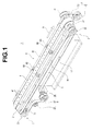
- a conveyor 1 includes an elastic conveying member 4 that is looped around at least a first rotation shaft (hereinafter referred to also as “drive shaft”) 2 and a second rotation shaft (hereinafter referred to also as “driven shaft”) 3, and rotates endlessly due to the drive of the first rotation shaft 2 (a direction indicated by an arrow A, that is, a conveying direction of a conveyance object in FIGS. 1 to 4 ).
- drive shaft a first rotation shaft
- driven shaft second rotation shaft
- the conveyor 1 includes the rotatable drive shaft 2, the rotatable driven shaft 3 disposed apart from the drive shaft, and an elastic conveying member 4 that has an inner peripheral portion being looped around the drive shaft 2 and the driven shaft 3 so as to come in contact (pressure contact) with the respective outer peripheral portions thereof, and rotates endlessly for conveying the conveyance object.
- the conveyor 1 further includes transmitting means 5 for transmitting the drive of the drive shaft (first rotation shaft) 2 to the driven shaft (second rotation shaft) 3 so that the drive of the drive shaft (first rotation shaft) 2 and the driven shaft (second rotation shaft) 3 are synchronous with each other.
- the conveyor 1 further includes the transmitting means 5 for transmitting the drive of the drive shaft 2 to the driven shaft 3 so that the driven shaft 3 rotates in synchronism with the drive shaft 2 to which the drive is transmitted to rotate, and the drive is transmitted from the respective drive shaft 2 and driven shaft 3 to the conveying member 4.
- the transmitting means 5 includes a transmitting member 51 that is looped around at least the drive shaft 2 (the first rotation shaft) and the driven shaft (the second rotation shaft) 3, and rotates endlessly so as to transmit the drive of the drive shaft (the first rotation shaft) 2 to the driven shaft (the second rotation shaft) 3. More specifically, the transmitting means 5 includes the transmitting member 51 including an inner peripheral portion being looped around the drive shaft 2 and the driven shaft 3 so as to be brought into contact with the respective outer peripheral portions thereof, and rotates endlessly so that the drive of the drive shaft 2 is transmitted to the driven shaft 3.
- the conveyor 1 includes suction means 6 for sucking the conveyance object to the conveying member 4.
- the conveyor 1 is so configured as to suck the conveyance object to the outer peripheral portion of the conveying member 4.
- the conveyor 1 includes a guide portion 61 that guides the conveying member 4 along a conveying direction of the conveyance object, and the conveying member 4 has a plurality of through-holes 41.
- the guide portion 61 has a plurality of openings 62 that communicate with the plurality of through-holes 41 on a site that guides the conveying member 4, and is constructed to suck air from the plurality of openings 62 so as to suck the conveyance object to the conveying member 4.
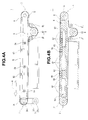
- the drive shaft 2 includes a drive shaft first direction change member (hereinafter referred to also as “drive shaft first pulley”) 21 including an outer peripheral portion that is brought into contact with the inner peripheral portion of the conveying member 4 to change the direction. Further, the drive shaft 2 includes a drive shaft second direction change member (hereinafter referred to also as “drive shaft second pulley”) 22 including an outer peripheral portion that is brought into contact with the inner peripheral portion of the transmitting member 51 to change the direction. Specifically, the drive shaft 2 includes the drive shaft second pulley 22 including a concave-convex engaging portion 23 (concave-convex shape not shown) on the outer peripheral portion thereof.
- the conveyor 1 includes drive receiving means 7 for transmitting the drive from a drive source (not shown) such as a motor to the drive shaft 2.
- the drive transmitting means 7 includes a drive receiving second pulley 71 that transmits the drive from the drive source to the drive receiving first pulley 24 disposed in the drive shaft 2, and a drive receiving belt 72 that transmits the drive (rotation) of the drive receiving second pulley 71 to the drive receiving first pulley 24.
- the driven shaft 3 includes a driven shaft first direction change member (hereinafter referred to also as “driven shaft first pulley”) 31 including an outer peripheral portion that is brought into contact with the inner peripheral portion of the conveying member 4 to change the direction.
- the driven shaft 3 includes the driven shaft first pulley 31 including the same diameter (or the same configuration) as that of the drive shaft first pulley 21.
- the driven shaft 3 includes a driven shaft second direction change member (hereinafter referred to also as “driven shaft second pulley”) 32 including an outer peripheral portion that is brought into contact with the inner peripheral portion of the conveying member 51 to change the direction.
- the driven shaft 3 includes the driven shaft second pulley 32 including the same diameter (or the same configuration) as that of the drive shaft second pulley 22.
- the driven shaft 3 includes the driven shaft second pulley 32 having an engaging portion 33 whose outer peripheral portion is concave-convex (concave-convex shape not shown).
- the conveying member 4 is constructed to rotate endlessly along a conveyance path of the conveyance object, that is, with a site along the conveyance path of the conveyance object. Specifically, the conveying member 4 is constructed to form the conveyance path on an upper side thereof, and allow the conveyance object to be put thereon for conveyance. Further, the conveying member 4 is shaped in a flexible flat belt.
- the conveying member 4 has a plurality of through-holes 41 at given intervals in the circumferential direction. Specifically, the conveying member 4 has the plurality of through-holes 41, which are uniserial in the width direction, arranged in parallel in the circumferential direction.
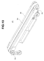
- the conveyor 1 includes first tension adjusting means 8 that can adjust a pressure under which the conveying member 4 is brought into contact with the drive shaft 2 and the driven shaft 3 so as to prevent slippage from occurring between the conveying member 4 and the drive shaft 2 (the drive shaft first pulley 21), and between the conveying member 4 and the driven shaft 3 (the driven shaft first pulley 31).
- the first tension adjusting means 8 includes a pair of fixed pulleys 81, 81 around which the conveying member 4 extends, and a displacement pulley 82 that can be displaced between the pair of fixed pulleys 81, 81.
- the first tension adjusting means 8 includes the pair of fixed pulleys 81, 81 whose outer peripheral portions are brought into contact with the outer peripheral portion of the conveying member 4, and the displacement pulley 82 whose outer peripheral portion is brought into contact with the inner peripheral portion of the conveying member 4 between sites of the conveying member 4 which are brought into contact with the pair of fixed pulleys 81, 81.
- the transmitting member 51 is constructed to rotate endlessly in parallel to the conveying member 4. Specifically, the transmitting member 51 makes the inner peripheral portion come in contact (press-contact) with the outer peripheral portions of the drive shaft second pulley 22 and the driven shaft second pulley 32 to rotate endlessly.
- the transmitting member 51 includes, on the inner peripheral portion thereof, an engaged portion 52 including a concave-convex shape (the concave-convex shape not shown) corresponding to the engaging portion 23 of the drive shaft second pulley 22 and the engaging portion 33 of the driven shaft second pulley 32.
- the engaged portion 52 is constructed to be engageable with the respective engaging portions 23 and 33 so as to prevent slippage from occurring between the transmitting member 51 and the drive shaft second pulley 22 and between the transmitting member 51 and the driven shaft second pulley 32.
- the transmitting member 51 is a timing belt.
- the transmitting member 51 is constructed to transmit the drive from the drive shaft 2 (the drive shaft second pulley 22) to the driven shaft 3 (the driven shaft second pulley 32) before or simultaneously when the conveying member 4 transmits the drive of the drive shaft 2 (the drive shaft first pulley 21) to the driven shaft 3 (the driven shaft first pulley 31).
- the transmitting member 51 is constructed to make the stretch property smaller than that of the conveying member 4 when conveying the conveyance object.
- the transmitting member 51 can be made of a material smaller in the stretch property than the conveying member 4, can be larger in thickness than the conveying member 4, or can be formed by incorporating a reinforcement material into the conveying member 4.
- the conveyor 1 includes second tension adjusting means 9 that can adjust a pressure under which the transmitting member 51 is brought into contact with the drive shaft 2 and the driven shaft 3 so as to prevent slippage (skip between the engaging portions 23, 33 and the engaged portion 52) from occurring between the transmitting member 51 and the drive shaft 2 (the drive shaft second pulley 22), and between the transmitting member 51 and the driven shaft 3 (the driven shaft second pulley 32).
- the second tension adjusting means 9 includes a pair of fixed pulleys 91, 91 around which the transmitting member 51 extends, and a displacement pulley 92 that can be displaced between the pair of fixed pulleys 91, 91.
- the second tension adjusting means 9 includes the pair of fixed pulleys 91, 91 whose outer peripheral portions are brought into contact with the outer peripheral portion of the transmitting member 51, and the displacement pulley 92 whose outer peripheral portion is brought into contact with the inner peripheral portion of the transmitting member 51 between sites of the transmitting member 51 which are brought into contact with the pair of fixed pulleys 91, 91.
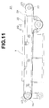
- the guide portion 61 is arranged between the drive shaft 2 and the driven shaft 3, and along the conveyance path of the conveyance object.
- the guide portion 61 is formed to be larger in width dimension than the conveying member 4, and guides the conveying member 4 by allowing a part of an upper surface portion of the guide portion 61 arranged along the conveyance path so as to be brought into slide contact with the conveying member 4.
- the guide portion 61 has the plurality of openings 62 arranged in parallel in the conveying direction of the conveyance object (nine in FIG. 4 ).
- the guide portion 61 has a plurality of communication portions 63 that are communicated with the plurality of openings 62 (three communication portions 63 that communicate with three openings 62 in FIG. 4 ).
- the guide portion 61 has a plurality of connection members 64 that communicate with the plurality of openings 62.
- the guide portion 61 includes, on the upper surface side thereof, a receiving portion 66 for receiving a rotator 65 that is brought into contact with the conveying member 4 (around which the conveying member 4 extends).
- the guide portion 61 has a plurality of receiving portions 66, 66 arranged between the respective communication portions 63 (two in FIGS. 1 to 4 ).
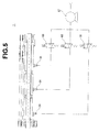
- the suction means 6 includes sucking-out means 67 such as a vacuum pump, which is connected to the connection members 64 as illustrated in FIG. 5 , so as to suck air from the plurality of openings 62 through the communication portions 63 and the connection members 64.
- sucking-out means 67 such as a vacuum pump
- the respective connection members 64 are connected to the sucking-out means 67 through pipes.
- respective valves 68 are disposed between the respective connection members 64 and the sucking-out means 67 so as to change a region where the conveyance object is sucked.
- the drive receiving belt 72 transmits the drive (rotation) of the drive receiving second pulley 71 to the drive receiving first pulley 24.
- the drive receiving first pulley 24 disposed in the drive shaft 2 rotates, the drive shaft 2, that is, the drive shaft first pulley 21 and the drive shaft second pulley 22 rotate.
- a site of the conveying member 4 having elasticity (stretch property) between the drive shaft 2 and the driven shaft 3 and along the conveyance path of the conveyance object may be stretched due to a friction with the guide portion 61.
- the transmitting member 51 transmits the drive to the driven shaft second pulley 32, that is, the driven shaft first pulley 31 before the conveying member 4 transmits the drive to the driven shaft first pulley 31.
- the drive is transmitted to the conveying member 4 from the drive shaft first pulley 21, and also the drive is transmitted to the conveying member 4 from the driven shaft first pulley 31 that rotates in synchronism with the drive shaft first pulley 21, the expansion and contraction of the site along the conveyance path of the conveyance object are regulated.
- the engaged portion 52 of the transmitting member 51 is engaged with the respective engaging portions 23 and 33 of the drive shaft second pulley 22 and the driven shaft second pulley 32, slippage is prevented from occurring between the transmitting member 51 and the drive shaft second pulley 22 and between the transmitting member 51 and the driven shaft second pulley 32.
- the drive shaft second pulley 22 and the driven shaft second pulley 32 that is, the drive shaft 2 and the driven shaft 3 rotate more accurately in synchronism with each other, in the conveying member 4 that is brought into contact with the drive shaft first pulley 21 and the driven shaft first pulley 31 to rotate endlessly, the expansion and contraction of the site along the conveyance path of the conveyance object is further regulated.
- the movement of the conveying member 4 accurately follows the movements of the drive shaft 2 and the driven shaft 3.
- the conveying member 4 transmits the drive to the driven shaft first pulley 31 simultaneously or substantially simultaneously when the conveyor 1 transmits the drive to the driven shaft second pulley 32, that is, the conveying member 4 and the transmitting member 51 transmits the drive of the drive shaft 2 to the driven shaft 3 simultaneously or substantially simultaneously.
- the upper surface portion of the guide portion 61 arranged between the drive shaft 2 and the driven shaft 3 and also along the conveyance path is brought into slide contact with the conveying member 4 to guide the conveying member 4 and convey the conveyance object put on the conveying member 4 in the conveying direction.
- the sucking-out means 67 sucks out air in the communication portions 63 through the pipes and the connection members 64. Therefore, the conveyance object put on the conveying member 4 is sucked to the outer peripheral portion of the conveying member 4 through the plurality of openings 62 in the guide portion 61 and the plurality of through-holes 41 in the conveying member 4. As a result, the conveyance object X is prevented from being displaced on the conveying member 4.
- valves 68 disposed between the connection members 64 and the sucking-out means 67 are opened or closed to suck air in each given region (each of the openings 62 communicating with the communication portions 63). Therefore, a region where the conveyance object is sucked to the outer peripheral portion of the conveying member 4 can be changed.
- the respective valves 68 are opened and closed in correspondence with the region where the conveyance object exists due to detecting means (not shown) or the like, the conveyance object X is sucked in only a necessary region of the conveying member 4.
- the frictional force generated between the conveying member 4 and the guide portion 61 can be reduced, the expansion and contraction of the conveying member 4 can be regulated.
- the transmitting member 51 transmits the drive of the drive shaft 2 (the first rotation shaft) 2 to the driven shaft (the second rotation shaft) 3, the drive shaft 2 and the driven shaft 3 rotate in synchronism with the result that the drive is transmitted to the conveying member 4 from the respective drive shaft 2 and driven shaft 3. Accordingly, because the conveying member 4 can be prevented from being partially or entirely expanded or contracted, the movement amount of the drive shaft 2 can be accurately followed by the movement amount of the conveyance object.
- the transmitting member 51 that is looped around the drive shaft 2 and the driven shaft 3 and rotates endlessly transmits the drive of the drive shaft 2 to the driven shaft 3. Accordingly, for example, because the tension of the conveying member 4 can be adjusted by the first tension adjusting means 8, and the transmitting member 51 can be adjusted by the second tension adjusting means 9, the tensions suitable for the respective members can be provided.
- the conveyance object X can be sucked to the conveying member 4 through the plurality of through-holes 41 disposed in the conveying member 4 communicating with the plurality of openings 62. Accordingly, the conveyance object can be prevented, when being conveyed, from being displaced on the conveying member 4.
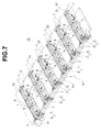
- FIGS. 6 to 8 parts denoted by the same symbols as those in FIGS. 1 to 5 represent the identical configurations or elements with the conveyor 1 in the above embodiment shown in FIGS. 1 to 5 .
- the elastic conveying members 4 is each looped around at least the drive shaft (the first rotation shaft) 2 and the driven shaft (the second rotation shaft) 3, and drive endlessly due to the drive of the drive shaft (the first rotation shaft) 2.
- the conveying members 4 are arranged in parallel in a direction orthogonal to the conveying direction (a direction indicated by an arrow C in FIG. 6 ) of the conveyance object X so as to convey the conveyance object X put across the conveying members 4 (six in FIGS. 6 and 7 ).
- the plurality of conveying members 4 are arranged apart from each other.
- the conveying device 100 is set to about 1,800 mm in a direction (width direction) orthogonal to the conveying direction of the conveyance object X so as to convey the conveyance object X of B0 size (1030 mm long and 1,456 mm wide).
- the conveying device 100 further includes the plurality of transmitting means 5 for transmitting the drive of the drive shaft (the first rotation shaft) 2 to the driven shaft (the second rotation shaft) 3.
- the conveying device 100 includes a plurality of suction means 6 for sucking the conveyance object X to the respective conveying members 4. That is, in the conveying device 100, the plurality of conveyors 1 are arranged in parallel in the direction orthogonal to the conveying direction of the conveyance object X so as to convey the conveyance object put across the respective conveying members 4. Further, the conveying device 100 is configured so that all of the drive shafts (the first rotation shafts) 2 are synchronized with each other to transmit the drive. Specifically, the conveying device 100 includes synchronizing means 101 for transmitting the drive to the respective drive shafts 2 so as to synchronize all of the drive shafts 2 with each other.
- the conveying device 100 includes a plurality of support portions 102 (seven in FIGS. 6 and 7 ) including respective planar portions which are flush or substantially flush with the conveying members 4 disposed in parallel, arranged between the respective conveying members 4.
- the conveying device 100 includes a plurality of plate support portions 102 larger in width dimension than the conveyors 1 (the conveying members 4) so as to put the sheet-like conveyance object X across the planar portions each formed in a plane and the conveying members 4 to ensure the flatness of the conveyance object.
- the synchronizing means 101 includes a drive transmission shaft 104 that transmits the drive directly from the drive source 103 such as a motor, and the drive transmission shaft 104 transmits the drive to the respective drive shafts 2 through the drive transmitting means 7 of the respective conveyors 1 so as to synchronize the drive shafts 2 of the respective conveyors 1 with each other to transmit the drive.
- the synchronizing means 101 includes the drive transmission shaft 104 equipped with the respective drive receiving second pulleys 71, and the drive receiving belts 72 that transmit the drive to the respective drive shafts 2 from the respective drive receiving second pulleys 71.
- Each of the support portions 102 is formed so that a frictional force occurring between the planar portion and the conveyance object X is smaller than a frictional force occurring between the conveying member 4 and the conveyance object X so as to regulate the occurrence of the frictional force between the support portion 102 and the conveyance object X.
- the support portions 102 are constructed to suck the conveyance object toward the respective planar portions.
- the support portions 102 are each constructed to include a plurality of holes 105 in the planar portion so as to suck air from the plurality of holes 105 to suck the conveyance object X.
- each of the support portions 102 are each configured so that the suction means 6 sucks the conveyance object X by force smaller than force for sucking the conveyance object to the conveying member 4 so as to prevent the conveyance object X from being displaced on the conveying member 4.
- each of the support portions 102 includes suction means 106 such as a fan for sucking air from the respective holes 105, which is internally communicated with the plurality of holes 105 formed in substantially the entire surface of the planar portion (refer to FIG. 8 ). More specifically, each support portion 102 includes the suction means 106 having force for sucking out air, which is smaller than that of the sucking-out means 67 of the conveyor 1.
- the sucking-out means 67 and the respective valves 68 are shared by the respective conveyors 1. Further, the conveying device 100 includes terminal valves 107 between the respective connection members 64 and the respective valves 68 so as to select the conveyor 1 which is available to suck.
- the conveyance object X is crossed over the planner portions of the support portions 102 and the outer peripheral portions of the conveying members 4. Then, through the suction of the air from the plurality of holes 105 formed in the planar portions of the support portions 102 by the suction means 106, the support portions 102 suck the conveyance object X toward the planner portion.
- the suction means 6 sucks the conveyance object X placed on the conveying members 4 to the conveying members 4, the flatness of the sheet-like conveyance object X is ensured. Note that, because the force for sucking the conveyance object X toward the planar portions by the support portions 102 is smaller than the force for sucking the conveyance object X to the conveying members 4 by the suction means 6, the flatness of the sheet-like conveyance object X is ensured while preventing the conveyance object X from being displaced on the conveying members 4.
- the respective valves 68 disposed between the connection members 64 and the sucking-out means 67 are opened or closed to change a region in which the conveyance object X is sucked to the conveying members 4. Further, the respective terminal valves 107 disposed between the respective connection members 64 and the respective valves 68 are opened or closed to select (change) the conveyor 1 to be sucked to the conveying members 4. As a result, because the respective valves 68 and the respective terminal valves 107 are opened or closed in correspondence with a region in which the conveyance object X exists, the conveyance object X is sucked in only a necessary region of the conveying members 4.
- the conveying device 100 As described above, in the conveying device 100 according to this embodiment, all of the drive shafts 2 are synchronized with each other to transmit the drive, and the transmitting means 5 transmits the drive of the drive shafts 2 to the respective driven shafts 3. Therefore, the plurality of conveying members 4 aligned in the direction orthogonal to the conveying direction of the conveyance object X can rotate in synchronism with each other while being prevented from being partially or entirely expanded or contracted. Accordingly, in the conveyance object X large in the width dimension (a dimension in the direction orthogonal to the conveying direction of the conveyance object), the movement amount of the drive shafts 2 can be accurately followed by the movement amount of the conveyance object.
- a precision in the conveyance of the conveyance object X for example, a precision in reciprocating feed can be improved, a joint treatment (an end treatment in image printing across the plurality of conveyance objects X) can be conducted according to a relation with output data. Further, because the conveyance object X can be stably conveyed without deterioration of precision, for example, during intermittent operation in a printer, a high-quality image can be obtained.
- the conveying device 100 in the conventional conveying device that can convey the conveyance object X of B0 size by one conveying member (belt) large in width dimension, because the width dimension is large, it is difficult to apply equal tensions between the conveying member and the drive shaft, and between the conveying member and the driven shaft, resulting in such a problem that the conveying members are partially expanded or contracted to be snaked.
- the conveying device 100 in the conveying device 100 according to this embodiment, the conveyors 1 each having the conveying member 4 designed to an appropriate width dimension are arranged in parallel so as to prevent the above problem from occurring.
- the conveying member 4 when the conveying member 4 is to be exchanged due to aging degradation, because the conveying member 4 is designed to the appropriate width dimension, exchange is easy, and the maintenance time can be reduced.
- the sheet-like conveyance object X can be conveyed while the flatness is ensured.
- the suction means 6 sucks the conveyance object X to the conveying member 4, and the support portions 102 suck the conveyance object X toward the planar portions, the sheet-like conveyance object can be conveyed while further ensuring the flatness.
- the force of the support portions 102 for sucking the conveyance object X is smaller than force of the suction means 6 for sucking the conveyance object X to the conveying member 4, the conveyance object X can be prevented from being displaced on the conveying member 4.
- the conveying device 100 (the conveyor 1) according to this embodiment can convey a curved sheet-like conveyance object X while correcting the conveyance object X to ensure the flatness thereof.
- the conveyance object X can be conveyed without contacting with one surface (lower surface) of the conveyance object X, for example, the conveyance object X having one surface (gloss surface) to be printed by a printer, which undesirably is brought into contact with a roller or the like can be stably conveyed without deterioration of precision. As a result, a high-quality image or the like can be obtained.
- the conveyor 1 according to the present invention are not limited to the above-mentioned embodiments, but can be variously modified without departing from the subject matter of the appended claims.
- detecting means for opening or closing the valves 68 and the terminal valves 107 in correspondence with a region in which the conveyance object X exists for example, a sensor (photoelectric sensor, limit switch, or the like) for detecting a position of the conveyance object X may be applied.
- the sensors can be arranged at given intervals in the conveying direction to detect the region in which the conveyance object X exists in the conveying direction.
- the sensors can be arranged on the conveyance inlet at given intervals in the width direction (a direction orthogonal to the conveying direction) to detect the region in which the conveyance object X exists in the width direction.
- a displacement detection sensor for example, encoder
- the region in which the conveyance object X exists can be detected according to size data of the conveyance object X and the movement amount of the rotator 65.
- another rotator can be disposed to put the conveyance object X between the rotator 65 in the guide portion 61 and the another rotator so that the conveyance object X is conveyed while being put between the pair of rotators under pressure. According to this configuration, even if the support portion 102 sucks the conveyance object X toward the planar portion, the conveyance object X can be surely prevented from moving with respect to the sucked side of the conveying member 4.
- a pair of correction rollers that put the conveyance object X therebetween under pressure may be disposed on the conveyance inlet so that the axial direction is toward the direction orthogonal to the conveying direction of the conveyance object X so as to ensure the flatness of the curved sheet-like conveyance object X.
- the pair of correction rollers may be so formed as to increase the diameter thereof toward both ends from the central portion in the axial direction. According to such structure described above, because the sheet-like conveyance object X is carried in so as to be pulled from the central portion toward both ends thereof, the flatness of the conveyance object X can be more surely ensured.
- the suction means 6 may be configured so that the force for sucking the conveyance object X to the conveying member 4 can be adjusted.
- conditions such as a material or thickness of the conveyance object X may be so selected as to automatically adjust the force.
- the valves 68 or the respective terminal valves 107 may be formed of flow (opening) control valves, or the air suck-out amount of the sucking-out means 67 can be adjusted by, for example, an inverter.
- the force for sucking the conveyance object X by the support portions 102 can be adjustably configured.
- a sucking force for sucking the conveyance object X to the conveying member 4 by the suction means 6 may be reduced (or vice versa) toward both ends thereof from the central portion in the width direction (a direction orthogonal to the conveying direction of the conveyance object X). Further, the respective conveying members 4 do not execute suction at the same time, but the respective conveying members 4 may sequentially execute suction from the central portion toward both ends thereof in the width direction. According to such structure described above, the sheet-like conveyance object X can be conveyed while the flatness is more ensured.
- the conveyance path is formed on the upper side of the conveying member 4 .
- the present invention is not limited to the above case, but there may be applied a case in which the conveyance path is formed on the lateral side or the lower side of the conveying member 4 to suck the conveyance object X to the conveying member 4 for conveyance.
- the conveying member 4 is elongated in the conveying direction of the conveyance object.
- the present invention is not limited to this case, but the conveying member 4 may be elongated in a direction orthogonal to the conveyance object, that is, may be widened.
- the conveying member 4 includes, on the inner peripheral portion, a concavo-convex engaging portion disposed on the outer peripheral portion of the drive shaft first pulley, and a concavo-convex engaged portion corresponding to the concavo-convex engaging portion disposed on the outer peripheral portion of the driven shaft first pulley.
- the engaged portions may be constructed to be engageable with the respective engaging portions so as to prevent slippage from occurring between the conveying member 4 and the drive shaft first pulley, and between the conveying member 4 and the driven shaft first pulley.
- the conveying member 4 is arranged such that the through-holes 41 are disposed in a line in the width direction.
- the present invention is not limited to this case.
- the conveying member may include the through-holes arranged in parallel in the width direction.
- the conveying member may be shaped in bubble (sponge) to provide infinite through-holes.
- the transmitting means 5 is the transmitting means 5 of the timing belt.
- the present invention is not limited to this case.
- the transmitting means may be formed of a gear mechanism or a link mechanism other than the wrapping drive.
- the wrapping drive there may be applied the wrapping drive as well as a wire rope drive, a flat belt drive, a V-belt drive, or a chain drive.
- the transmitting member 51 is looped around the drive shaft (the first rotation shaft) 2 and the driven shaft (the second rotation shaft) 3 to rotate endlessly.
- the present invention is not limited to this case.
- the transmitting means 5 may be looped around a rotation shaft operationally coupled with the drive shaft 2 and a rotation shaft operationally coupled with the driven shaft 3 to rotate endlessly.
- the transmitting member 51 may be constructed to be operationally coupled with the drive shaft 2 and the driven shaft 3 to rotate endlessly.
- the present invention is not limited to this case.
- one opening may be formed along the conveying direction of the guide portion.
- the region in which the conveyance object is sucked to the conveying member 4 can be adjusted (changed) with the results that, for example, a power capacity of the sucking-out means 67 for sucking the conveyance object can be reduced.
- the suction means 6 sucks air from the plurality of openings 62 to suck the conveyance object which is put on the conveying member 4 to the conveying member 4 has been described.
- the present invention is not limited to this case.
- the suction means may suck the conveyance object to the conveying member 4 by electrostatic suction.
- the present invention is not limited to this case.
- No drive transmitting means 7 may be provided.
- the drive source may be connected directly to the drive shaft 2 so that the drive is transmitted to the drive shaft 2.
- the present invention is not limited to this case.
- the plurality of conveying members 4 (conveyors 1) may be arranged in contact (close contact) with each other.
- the conveying device may be configured so that the plurality of conveying members 4 (conveyor 1) are brought into or out of contact with each other.
- the present invention is not limited to this case.
- the plurality of conveying members (conveyors) different in the dimension in the conveying direction may be arranged in parallel. Further, the plurality of conveying members (conveyors) may be arranged so that the respective drive shafts 2 do not coincide in the axial line with each other. Further, the plurality of conveying members (conveyors) may be arranged so that the respective driven shafts 3 do not coincide in the axial line with each other.
- the drive transmission shaft 104 may be the respective drive shafts 2, that is, the respective conveying members 4 may be looped around the drive transmission shaft 104 as the drive shaft 2.
- the drive transmission shaft 104 may include the drive shaft first pulleys 21 that are brought into contact with the respective conveying members 4.
- at least all of the first rotation shafts (drive shafts) 2 are synchronized with each other to transmit the drive.
- the driven shafts 3 of the respective conveyors 1 are a common transmission shaft, that is, the respective conveying members 4 may be looped around the common transmission shaft as the driven shafts 3.
- the common transmission shaft may include the driven shaft first pulley 31 that is brought into contact with the respective conveying members 4.
- the first rotation shafts (drive shafts) 2 but also all of the second rotation shafts (driven shafts) 3 may be synchronized with each other to transmit the drive.
- the conveying member 4 when the conveying member 4 is exchanged, the work of allowing the drive transmission shaft 104 and the common transmission shaft of the driven shafts to pass through each conveying member 4 is not required. Therefore, the exchange work of the conveying member 4 is easy.
- the conveying members 4 (conveyors 1) are each equipped with the transmitting member 51 .
- the present invention is not limited to this case.
- the drive can be transmitted to the respective driven shafts 3 from the common transmission shaft 108 as with the drive transmission shaft 104 and the drive receiving means 7.
- one transmitting means (transmitting member) 109 can be disposed between the common transmission shaft 108 and the drive transmission shaft 104.
- the present invention is not limited to this case.
- support members in which each support is shaped in a bar can be arranged in parallel. According to this configuration, because an area where the conveyance object X is brought into contact with the support portions can be reduced, the frictional force occurring between the support and the conveyance object X can be reduced.
- the support portions are arranged so that the site of each support which is brought into contact with the conveyance object X during conveyance can be arranged to be flush or substantially flush with the outer peripheral portion of the conveying member 4.
- the sheet-like conveyance object X can be conveyed while the flatness is ensured.
- the support portions 102 may be movably configured.
- the support portions 102 may be constructed to be movable in a direction orthogonal to the planar portion (vertical direction). According to this configuration, when the conveyance object X which is rigid is conveyed, the support portions 102 are moved downward so that the conveyance object X is brought out of contact with the support portions 102. As a result, because no frictional force occurs between the conveyance object X and the support portions 102, the conveyance property of the conveyance object X can be improved.
- each of the support portions 102 sucks air from the plurality of holes 105 in the planar portion to suck the conveyance object X
- the present invention is not limited to this case. Air may be belched from the plurality of holes 105. According to this configuration, when the conveyance object X is a sheet, the frictional force can be prevented from occurring between the support portion 102 and the conveyance object X while the flatness of the conveyance object X is ensured.
- the present invention can be applied to, for example, a conveying device for a recording medium of a printer which can be used in an apparatus having the conveying device.
Landscapes
- Engineering & Computer Science (AREA)
- Mechanical Engineering (AREA)
- Delivering By Means Of Belts And Rollers (AREA)
Claims (5)
- Fördergerät (1), umfassend ein elastisches Förderelement (4), welches um zumindest eine erste Drehwelle (2) und eine zweite Drehwelle (3) geschlungen ist, und unendlich durch Antrieb der ersten Drehwelle dreht, wobei
das Fördergerät weiter Übertragungsmittel (5) zum Übertragen des Antriebs der ersten Drehwelle auf die zweite Drehwelle umfasst, so dass die erste Drehwelle und die zweite Drehwelle miteinander synchronisiert sind;
das Förderelement (4) Ansaugmittel (6) zum Ansaugen des Beförderungsobjekts beinhaltet;
das Ansaugmittel (6) einen Leitabschnitt (61) zum Leiten des Förderelements entlang einer Förderrichtung des Beförderungsobjekts beinhaltet;
das Förderelement (4) mehrere Durchgangslöcher (41) beinhaltet; und
der Leitabschnitt mehrere Öffnungen (62) beinhaltet, die mit den Durchgangslöchern an einer Stelle in Verbindung stehen, die das Förderelement leitet, und Luft aus den Öffnungen ansaugt, um das Beförderungsobjekt an das Förderelement anzusaugen; und
das Übertragungsmittel ein Übertragungselement (51) beinhaltet, welches um zumindest die erste Drehwelle (2) und die zweite Drehwelle (3) geschlungen ist und unendlich dreht, um den Antrieb der ersten Drehwelle auf die zweite Drehwelle zu übertragen;
dadurch gekennzeichnet, dass:der Leitabschnitt (61) mehrere Verbindungsabschnitte (63) beinhaltet, welche entlang der Förderrichtung angeordnet sind und mit den mehreren Öffnungen (62) in Verbindung stehen, wobei Luft aus den Öffnungen mit Hilfe der Verbindungsabschnitte (63) angesaugt wird, undein Rotator (65), welcher mit dem Förderelement in Kontakt gebracht wird, zwischen angrenzenden Paaren der Verbindungsabschnitte (63) angeordnet ist. - Fördergerät nach Anspruch 1, wobei:der Leitabschnitt (61) einen Aufnahmeabschnitt (66) zum Aufnehmen des Rotators beinhaltet;die mehreren der Öffnungen (62) mit den Durchgangslöchern in einem Leitbereich des Leitabschnitts, welcher das Förderelement leitet, in Verbindung stehen;der Leitbereich durch den Aufnahmeabschnitt in mehrere Stücke unterteilt ist; undein Verbindungselement (64) für die mehreren Öffnungen in jedem Stück des Leitbereichs bereitgestellt ist, wobei das Verbindungselement mit jeder der mehreren Öffnungen in dem jeweiligen Stück des Leitbereichs in Verbindung steht und mit dem Ansaugmittel in Verbindung steht, so dass das Beförderungsobjekt an das Förderelement angesaugt wird.
- Fördergerät nach Anspruch 2, des Weiteren umfassend:ein erstes Spannungsanpassungsmittel (8) zum Ändern eines Drucks, unter welchem das Förderelement (4) mit der ersten Drehwelle (2) und der zweiten Drehwelle (3) in Kontakt gebracht wird, um zu verhindern, dass ein Schlupf zwischen dem Förderelement und der ersten Drehwelle und der zweiten Drehwelle auftritt; undein zweites Spannungsanpassungsmittel (9) zum Ändern eines Drucks, unter welchem das Übertragungselement (51) mit der ersten Drehwelle und der zweiten Drehwelle in Kontakt gebracht wird, um zu verhindern, dass ein Schlupf zwischen dem Übertragungselement und der ersten Drehwelle und der zweiten Drehwelle auftritt;
- Fördervorrichtung umfassend:mehrere der Fördergeräte (1) nach Anspruch 1, welche parallel angeordnet und voneinander beabstandet sind, wobei die mehreren der Fördergeräte so angeordnet sind, dass sie synchron miteinander angetrieben werden;Trägerabschnitte (102), die jeweils einen ebenflächigen Abschnitt zwischen den jeweiligen Förderelementen beinhalten, wobei der ebenflächige Abschnitt so angeordnet ist, dass er mit dem Förderelement bündig oder im Wesentlichen bündig ist;mehrere Antriebswellen zum Antreiben der Fördergeräte; undSynchronisationsmittel (101), die jeweils an den ersten Drehwellen (2) bereitgestellt sind, zum Synchronisieren der Drehung der Antriebswelle mit der Drehung der ersten Drehwelle eines anderen Fördergeräts, um die Drehung zu der ersten Drehwelle zu übertragen.
- Fördervorrichtung nach Anspruch 4, wobei:jeder der Trägerabschnitte (102) so konstruiert ist, dass er das Beförderungsobjekt (X) in Richtung des ebenflächigen Abschnitts hin ansaugt; undTrägerabschnitte so konstruiert sind, dass das Beförderungsobjekt bei einer Kraft angesaugt wird, die geringer als eine Kraft zum Ansaugen des Beförderungsobjekts an die Förderelemente ist, so dass verhindert wird, dass sich das Beförderungsobjekt in Bezug auf eine angesaugte Stelle des Förderelements bewegt.
Applications Claiming Priority (2)
| Application Number | Priority Date | Filing Date | Title |
|---|---|---|---|
| JP2008002858A JP2009161342A (ja) | 2008-01-10 | 2008-01-10 | 搬送体及び搬送装置 |
| PCT/JP2008/072619 WO2009087854A1 (ja) | 2008-01-10 | 2008-12-12 | 搬送体及び搬送装置 |
Publications (3)
| Publication Number | Publication Date |
|---|---|
| EP2241523A1 EP2241523A1 (de) | 2010-10-20 |
| EP2241523A4 EP2241523A4 (de) | 2012-08-29 |
| EP2241523B1 true EP2241523B1 (de) | 2015-01-21 |
Family
ID=40852979
Family Applications (1)
| Application Number | Title | Priority Date | Filing Date |
|---|---|---|---|
| EP08870335.0A Not-in-force EP2241523B1 (de) | 2008-01-10 | 2008-12-12 | Förderkörper und fördervorrichtung |
Country Status (4)
| Country | Link |
|---|---|
| US (1) | US8636139B2 (de) |
| EP (1) | EP2241523B1 (de) |
| JP (1) | JP2009161342A (de) |
| WO (1) | WO2009087854A1 (de) |
Families Citing this family (18)
| Publication number | Priority date | Publication date | Assignee | Title |
|---|---|---|---|---|
| WO2012009765A1 (en) * | 2010-07-23 | 2012-01-26 | Newcastle Innovation Limited | Rail conveyor system |
| CN102774599A (zh) * | 2011-05-12 | 2012-11-14 | 鸿富锦精密工业(深圳)有限公司 | 传送装置 |
| DE102011079981A1 (de) * | 2011-07-28 | 2013-01-31 | Homag Holzbearbeitungssysteme Gmbh | Werkstücktransportsystem |
| WO2013016833A1 (de) * | 2011-07-29 | 2013-02-07 | Wrh Walter Reist Holding Ag | Fördereinrichtung mit einem flächig ausgedehnten förderorgan |
| DE102011117494A1 (de) * | 2011-10-31 | 2013-05-02 | Eastman Kodak Company | Vorrichtung und Verfahren zum Bedrucken einer Substratbahn |
| FR2986788B1 (fr) * | 2012-02-10 | 2015-07-24 | Aktid | Dispositif de convoyage et de tri multi-bande |
| CN103770481A (zh) * | 2012-10-23 | 2014-05-07 | 玉田元创包装机械制造有限公司 | 自动吸风定位系统 |
| CN103927813B (zh) * | 2014-04-24 | 2016-05-25 | 中国人民银行印制科学技术研究所 | 片状材料成像装置及使用该装置的清分机 |
| ES2721780T3 (es) | 2014-11-19 | 2019-08-05 | Bobst Mex Sa | Dispositivo de control óptico de una cara de un recorte, máquina de tratamiento de recortes y plegadora-encoladora que comprende el dispositivo |
| CN104555241A (zh) * | 2014-12-02 | 2015-04-29 | 爱彼思(苏州)自动化科技有限公司 | 一种同步带传送装置及其在外观检测装置中的应用 |
| CN108137240A (zh) * | 2015-10-22 | 2018-06-08 | 惠普深蓝有限责任公司 | 感测输送机中的物品 |
| JP6105764B2 (ja) * | 2016-01-20 | 2017-03-29 | 株式会社ダイヘン | ベルト駆動装置 |
| EP3480143A4 (de) * | 2016-06-30 | 2020-02-26 | Ace Machinery Co. Ltd. | Transportvorrichtung |
| US9783373B1 (en) * | 2016-07-12 | 2017-10-10 | Sweed Machinery, Inc. | Veneer transporting apparatus |
| JP6829814B2 (ja) * | 2017-03-13 | 2021-02-17 | 日本電気硝子株式会社 | ガラスフィルムの製造方法 |
| CN108438969A (zh) * | 2018-04-11 | 2018-08-24 | 苏州智码数码科技有限公司 | 消振传输机构及包括该机构的折叠机 |
| CN108439010A (zh) * | 2018-04-11 | 2018-08-24 | 苏州智码数码科技有限公司 | 收料组件、折叠收料机构及包括该机构的折叠机 |
| ES2847172T3 (es) | 2018-05-17 | 2021-08-02 | Fagor Arrasate S Coop | Dispositivo de transporte de piezas |
Family Cites Families (18)
| Publication number | Priority date | Publication date | Assignee | Title |
|---|---|---|---|---|
| DE4012948A1 (de) * | 1990-04-24 | 1991-10-31 | Roland Man Druckmasch | Vorrichtung zum foerdern von druckbogen |
| DE4243486C1 (de) * | 1992-12-22 | 1994-04-07 | Heidelberger Druckmasch Ag | Anlegetisch einer Bogendruckmaschine |
| JPH082770A (ja) | 1994-06-16 | 1996-01-09 | Canon Inc | シート搬送装置及びシート搬送装置を備えた画像形成装置 |
| JPH0825778A (ja) | 1994-07-14 | 1996-01-30 | Riso Kagaku Corp | 孔版印刷装置 |
| DE4442629C2 (de) * | 1994-12-01 | 1998-05-07 | Heidelberger Druckmasch Ag | Saugbändertisch |
| JP3662385B2 (ja) * | 1997-04-18 | 2005-06-22 | オムロン株式会社 | 用紙搬送装置 |
| JPH11255392A (ja) * | 1998-03-09 | 1999-09-21 | Isowa Corp | シートスタッカのシート積上げ装置、サクションコンベア及びサクションベルト |
| JP3759327B2 (ja) * | 1999-01-26 | 2006-03-22 | 株式会社リコー | シート給送装置 |
| US6216848B1 (en) * | 1999-04-09 | 2001-04-17 | Profold, Inc. | Vacuum table conveying apparatus and associated methods |
| JP2001088977A (ja) | 1999-09-20 | 2001-04-03 | Noritsu Koki Co Ltd | プリンター装置 |
| DE10024298C2 (de) * | 2000-05-17 | 2002-04-25 | Winkler & Duennebier Ag | Vorrichtung zum Transport von Briefhüllenzuschnitten in einer Briefhüllenherstellungsmaschine |
| JP2002179313A (ja) * | 2000-12-14 | 2002-06-26 | Tohoku Ricoh Co Ltd | 用紙吸着搬送装置及び印刷装置 |
| JP2003104600A (ja) * | 2001-10-01 | 2003-04-09 | Noritsu Koki Co Ltd | インクジェット式プリンタ |
| DE20214984U1 (de) | 2002-09-27 | 2002-12-05 | Roland Man Druckmasch | Fördertisch |
| JP2006021881A (ja) * | 2004-07-08 | 2006-01-26 | Canon Finetech Inc | 紙葉類搬送装置 |
| US7575114B2 (en) * | 2004-11-05 | 2009-08-18 | Cp Packaging, Inc. | Conveyor belt construction for a platen-type conveyor |
| JP2006160504A (ja) * | 2004-12-10 | 2006-06-22 | Canon Finetech Inc | 搬送装置 |
| JP2007301868A (ja) * | 2006-05-12 | 2007-11-22 | Ishida Co Ltd | プリンタ |
-
2008
- 2008-01-10 JP JP2008002858A patent/JP2009161342A/ja active Pending
- 2008-12-12 WO PCT/JP2008/072619 patent/WO2009087854A1/ja active Application Filing
- 2008-12-12 EP EP08870335.0A patent/EP2241523B1/de not_active Not-in-force
- 2008-12-12 US US12/735,358 patent/US8636139B2/en not_active Expired - Fee Related
Also Published As
| Publication number | Publication date |
|---|---|
| JP2009161342A (ja) | 2009-07-23 |
| US8636139B2 (en) | 2014-01-28 |
| WO2009087854A1 (ja) | 2009-07-16 |
| US20110139581A1 (en) | 2011-06-16 |
| EP2241523A1 (de) | 2010-10-20 |
| EP2241523A4 (de) | 2012-08-29 |
Similar Documents
| Publication | Publication Date | Title |
|---|---|---|
| EP2241523B1 (de) | Förderkörper und fördervorrichtung | |
| US20170015504A1 (en) | Device for conveying elongate objects | |
| EP1847493A3 (de) | Bogenfördervorrichtung, Bildabtastvorrichtung und Bildgebungsvorrichtung | |
| EP1908713A3 (de) | Blattfördervorrichtung und damit ausgestattete Bildgebungsvorrichtung | |
| US10258511B2 (en) | Folding device and folding method using same | |
| EP1970335A3 (de) | Vorrichtung und Verfahren zur Erkennung von Blattabweichungen | |
| JP5003990B2 (ja) | ガラス板の加工方法及びその装置 | |
| JP6282468B2 (ja) | 搬送装置 | |
| WO2009156926A3 (en) | Inspection system for inspecting the quality of printed sheets | |
| KR910004449A (ko) | 종이 장 이송장치 | |
| US4373231A (en) | Apparatus for cutting connecting portions of a sausage chain | |
| KR20090028837A (ko) | 다이 절단 프레스의 공급 테이블상의 시트를 이송하는 보조구동 장치 | |
| EP1616819A1 (de) | Verstärkungsvorrichtung für rohrförderer und diese verwendende rohrfördereinrichtung | |
| US8113498B2 (en) | Method and device for the transfer of signatures | |
| JP2010155701A (ja) | 排紙装置および両面印刷機 | |
| CN217376274U (zh) | 一种书籍转向设备 | |
| US20240034567A1 (en) | Angled transfer with roller chain | |
| JP2008132777A (ja) | 枚葉紙状基材を仕上げ加工するための装置および方法 | |
| KR20150010933A (ko) | 벨트 컨베이어 | |
| JP4250118B2 (ja) | 包装袋押圧機構及びそれを備えたシールチェック装置 | |
| RU2494952C2 (ru) | Устройство для манипулирования листовым материалом, система обработки листового материала и способ обработки | |
| JP2018083679A (ja) | ベルトコンベヤ装置 | |
| CN210709224U (zh) | 一种用于pvc板的输送装置 | |
| JPH07215455A (ja) | フリーフローコンベア装置 | |
| JP5227575B2 (ja) | 整列移載装置 |
Legal Events
| Date | Code | Title | Description |
|---|---|---|---|
| PUAI | Public reference made under article 153(3) epc to a published international application that has entered the european phase |
Free format text: ORIGINAL CODE: 0009012 |
|
| 17P | Request for examination filed |
Effective date: 20100810 |
|
| AK | Designated contracting states |
Kind code of ref document: A1 Designated state(s): AT BE BG CH CY CZ DE DK EE ES FI FR GB GR HR HU IE IS IT LI LT LU LV MC MT NL NO PL PT RO SE SI SK TR |
|
| AX | Request for extension of the european patent |
Extension state: AL BA MK RS |
|
| DAX | Request for extension of the european patent (deleted) | ||
| A4 | Supplementary search report drawn up and despatched |
Effective date: 20120730 |
|
| RIC1 | Information provided on ipc code assigned before grant |
Ipc: B65H 5/02 20060101AFI20120724BHEP Ipc: B65H 5/22 20060101ALI20120724BHEP Ipc: B65H 29/24 20060101ALI20120724BHEP |
|
| 17Q | First examination report despatched |
Effective date: 20140217 |
|
| REG | Reference to a national code |
Ref country code: DE Ref legal event code: R079 Ref document number: 602008036510 Country of ref document: DE Free format text: PREVIOUS MAIN CLASS: B65H0005020000 Ipc: B65H0005220000 |
|
| GRAP | Despatch of communication of intention to grant a patent |
Free format text: ORIGINAL CODE: EPIDOSNIGR1 |
|
| RIC1 | Information provided on ipc code assigned before grant |
Ipc: B65H 11/00 20060101ALI20140930BHEP Ipc: B65H 5/22 20060101AFI20140930BHEP Ipc: B65G 23/34 20060101ALI20140930BHEP Ipc: B65G 15/12 20060101ALI20140930BHEP Ipc: B65G 21/20 20060101ALI20140930BHEP Ipc: B65H 29/24 20060101ALI20140930BHEP |
|
| INTG | Intention to grant announced |
Effective date: 20141028 |
|
| GRAS | Grant fee paid |
Free format text: ORIGINAL CODE: EPIDOSNIGR3 |
|
| GRAA | (expected) grant |
Free format text: ORIGINAL CODE: 0009210 |
|
| AK | Designated contracting states |
Kind code of ref document: B1 Designated state(s): AT BE BG CH CY CZ DE DK EE ES FI FR GB GR HR HU IE IS IT LI LT LU LV MC MT NL NO PL PT RO SE SI SK TR |
|
| REG | Reference to a national code |
Ref country code: GB Ref legal event code: FG4D |
|
| REG | Reference to a national code |
Ref country code: CH Ref legal event code: EP |
|
| REG | Reference to a national code |
Ref country code: IE Ref legal event code: FG4D |
|
| REG | Reference to a national code |
Ref country code: DE Ref legal event code: R096 Ref document number: 602008036510 Country of ref document: DE Effective date: 20150305 |
|
| REG | Reference to a national code |
Ref country code: AT Ref legal event code: REF Ref document number: 709064 Country of ref document: AT Kind code of ref document: T Effective date: 20150315 |
|
| REG | Reference to a national code |
Ref country code: NL Ref legal event code: VDEP Effective date: 20150121 |
|
| REG | Reference to a national code |
Ref country code: AT Ref legal event code: MK05 Ref document number: 709064 Country of ref document: AT Kind code of ref document: T Effective date: 20150121 |
|
| REG | Reference to a national code |
Ref country code: LT Ref legal event code: MG4D |
|
| PG25 | Lapsed in a contracting state [announced via postgrant information from national office to epo] |
Ref country code: HR Free format text: LAPSE BECAUSE OF FAILURE TO SUBMIT A TRANSLATION OF THE DESCRIPTION OR TO PAY THE FEE WITHIN THE PRESCRIBED TIME-LIMIT Effective date: 20150121 Ref country code: ES Free format text: LAPSE BECAUSE OF FAILURE TO SUBMIT A TRANSLATION OF THE DESCRIPTION OR TO PAY THE FEE WITHIN THE PRESCRIBED TIME-LIMIT Effective date: 20150121 Ref country code: LT Free format text: LAPSE BECAUSE OF FAILURE TO SUBMIT A TRANSLATION OF THE DESCRIPTION OR TO PAY THE FEE WITHIN THE PRESCRIBED TIME-LIMIT Effective date: 20150121 Ref country code: SE Free format text: LAPSE BECAUSE OF FAILURE TO SUBMIT A TRANSLATION OF THE DESCRIPTION OR TO PAY THE FEE WITHIN THE PRESCRIBED TIME-LIMIT Effective date: 20150121 Ref country code: BG Free format text: LAPSE BECAUSE OF FAILURE TO SUBMIT A TRANSLATION OF THE DESCRIPTION OR TO PAY THE FEE WITHIN THE PRESCRIBED TIME-LIMIT Effective date: 20150421 Ref country code: FI Free format text: LAPSE BECAUSE OF FAILURE TO SUBMIT A TRANSLATION OF THE DESCRIPTION OR TO PAY THE FEE WITHIN THE PRESCRIBED TIME-LIMIT Effective date: 20150121 Ref country code: NO Free format text: LAPSE BECAUSE OF FAILURE TO SUBMIT A TRANSLATION OF THE DESCRIPTION OR TO PAY THE FEE WITHIN THE PRESCRIBED TIME-LIMIT Effective date: 20150421 |
|
| PG25 | Lapsed in a contracting state [announced via postgrant information from national office to epo] |
Ref country code: GR Free format text: LAPSE BECAUSE OF FAILURE TO SUBMIT A TRANSLATION OF THE DESCRIPTION OR TO PAY THE FEE WITHIN THE PRESCRIBED TIME-LIMIT Effective date: 20150422 Ref country code: PL Free format text: LAPSE BECAUSE OF FAILURE TO SUBMIT A TRANSLATION OF THE DESCRIPTION OR TO PAY THE FEE WITHIN THE PRESCRIBED TIME-LIMIT Effective date: 20150121 Ref country code: IS Free format text: LAPSE BECAUSE OF FAILURE TO SUBMIT A TRANSLATION OF THE DESCRIPTION OR TO PAY THE FEE WITHIN THE PRESCRIBED TIME-LIMIT Effective date: 20150521 Ref country code: LV Free format text: LAPSE BECAUSE OF FAILURE TO SUBMIT A TRANSLATION OF THE DESCRIPTION OR TO PAY THE FEE WITHIN THE PRESCRIBED TIME-LIMIT Effective date: 20150121 Ref country code: NL Free format text: LAPSE BECAUSE OF FAILURE TO SUBMIT A TRANSLATION OF THE DESCRIPTION OR TO PAY THE FEE WITHIN THE PRESCRIBED TIME-LIMIT Effective date: 20150121 Ref country code: AT Free format text: LAPSE BECAUSE OF FAILURE TO SUBMIT A TRANSLATION OF THE DESCRIPTION OR TO PAY THE FEE WITHIN THE PRESCRIBED TIME-LIMIT Effective date: 20150121 |
|
| REG | Reference to a national code |
Ref country code: DE Ref legal event code: R097 Ref document number: 602008036510 Country of ref document: DE |
|
| PG25 | Lapsed in a contracting state [announced via postgrant information from national office to epo] |
Ref country code: RO Free format text: LAPSE BECAUSE OF FAILURE TO SUBMIT A TRANSLATION OF THE DESCRIPTION OR TO PAY THE FEE WITHIN THE PRESCRIBED TIME-LIMIT Effective date: 20150121 Ref country code: EE Free format text: LAPSE BECAUSE OF FAILURE TO SUBMIT A TRANSLATION OF THE DESCRIPTION OR TO PAY THE FEE WITHIN THE PRESCRIBED TIME-LIMIT Effective date: 20150121 Ref country code: SK Free format text: LAPSE BECAUSE OF FAILURE TO SUBMIT A TRANSLATION OF THE DESCRIPTION OR TO PAY THE FEE WITHIN THE PRESCRIBED TIME-LIMIT Effective date: 20150121 Ref country code: CZ Free format text: LAPSE BECAUSE OF FAILURE TO SUBMIT A TRANSLATION OF THE DESCRIPTION OR TO PAY THE FEE WITHIN THE PRESCRIBED TIME-LIMIT Effective date: 20150121 Ref country code: DK Free format text: LAPSE BECAUSE OF FAILURE TO SUBMIT A TRANSLATION OF THE DESCRIPTION OR TO PAY THE FEE WITHIN THE PRESCRIBED TIME-LIMIT Effective date: 20150121 |
|
| REG | Reference to a national code |
Ref country code: FR Ref legal event code: PLFP Year of fee payment: 8 |
|
| PLBE | No opposition filed within time limit |
Free format text: ORIGINAL CODE: 0009261 |
|
| STAA | Information on the status of an ep patent application or granted ep patent |
Free format text: STATUS: NO OPPOSITION FILED WITHIN TIME LIMIT |
|
| 26N | No opposition filed |
Effective date: 20151022 |
|
| PG25 | Lapsed in a contracting state [announced via postgrant information from national office to epo] |
Ref country code: IT Free format text: LAPSE BECAUSE OF FAILURE TO SUBMIT A TRANSLATION OF THE DESCRIPTION OR TO PAY THE FEE WITHIN THE PRESCRIBED TIME-LIMIT Effective date: 20150121 |
|
| PG25 | Lapsed in a contracting state [announced via postgrant information from national office to epo] |
Ref country code: SI Free format text: LAPSE BECAUSE OF FAILURE TO SUBMIT A TRANSLATION OF THE DESCRIPTION OR TO PAY THE FEE WITHIN THE PRESCRIBED TIME-LIMIT Effective date: 20150121 |
|
| PG25 | Lapsed in a contracting state [announced via postgrant information from national office to epo] |
Ref country code: BE Free format text: LAPSE BECAUSE OF FAILURE TO SUBMIT A TRANSLATION OF THE DESCRIPTION OR TO PAY THE FEE WITHIN THE PRESCRIBED TIME-LIMIT Effective date: 20150121 |
|
| PG25 | Lapsed in a contracting state [announced via postgrant information from national office to epo] |
Ref country code: MC Free format text: LAPSE BECAUSE OF FAILURE TO SUBMIT A TRANSLATION OF THE DESCRIPTION OR TO PAY THE FEE WITHIN THE PRESCRIBED TIME-LIMIT Effective date: 20150121 Ref country code: LU Free format text: LAPSE BECAUSE OF FAILURE TO SUBMIT A TRANSLATION OF THE DESCRIPTION OR TO PAY THE FEE WITHIN THE PRESCRIBED TIME-LIMIT Effective date: 20151212 |
|
| REG | Reference to a national code |
Ref country code: CH Ref legal event code: PL |
|
| GBPC | Gb: european patent ceased through non-payment of renewal fee |
Effective date: 20151212 |
|
| REG | Reference to a national code |
Ref country code: IE Ref legal event code: MM4A |
|
| PG25 | Lapsed in a contracting state [announced via postgrant information from national office to epo] |
Ref country code: IE Free format text: LAPSE BECAUSE OF NON-PAYMENT OF DUE FEES Effective date: 20151212 Ref country code: LI Free format text: LAPSE BECAUSE OF NON-PAYMENT OF DUE FEES Effective date: 20151231 Ref country code: GB Free format text: LAPSE BECAUSE OF NON-PAYMENT OF DUE FEES Effective date: 20151212 Ref country code: CH Free format text: LAPSE BECAUSE OF NON-PAYMENT OF DUE FEES Effective date: 20151231 |
|
| REG | Reference to a national code |
Ref country code: FR Ref legal event code: PLFP Year of fee payment: 9 |
|
| PG25 | Lapsed in a contracting state [announced via postgrant information from national office to epo] |
Ref country code: HU Free format text: LAPSE BECAUSE OF FAILURE TO SUBMIT A TRANSLATION OF THE DESCRIPTION OR TO PAY THE FEE WITHIN THE PRESCRIBED TIME-LIMIT; INVALID AB INITIO Effective date: 20081212 |
|
| PG25 | Lapsed in a contracting state [announced via postgrant information from national office to epo] |
Ref country code: CY Free format text: LAPSE BECAUSE OF FAILURE TO SUBMIT A TRANSLATION OF THE DESCRIPTION OR TO PAY THE FEE WITHIN THE PRESCRIBED TIME-LIMIT Effective date: 20150121 |
|
| PG25 | Lapsed in a contracting state [announced via postgrant information from national office to epo] |
Ref country code: MT Free format text: LAPSE BECAUSE OF FAILURE TO SUBMIT A TRANSLATION OF THE DESCRIPTION OR TO PAY THE FEE WITHIN THE PRESCRIBED TIME-LIMIT Effective date: 20150121 Ref country code: TR Free format text: LAPSE BECAUSE OF FAILURE TO SUBMIT A TRANSLATION OF THE DESCRIPTION OR TO PAY THE FEE WITHIN THE PRESCRIBED TIME-LIMIT Effective date: 20150121 |
|
| REG | Reference to a national code |
Ref country code: FR Ref legal event code: PLFP Year of fee payment: 10 |
|
| PGFP | Annual fee paid to national office [announced via postgrant information from national office to epo] |
Ref country code: DE Payment date: 20171206 Year of fee payment: 10 Ref country code: FR Payment date: 20171113 Year of fee payment: 10 |
|
| REG | Reference to a national code |
Ref country code: DE Ref legal event code: R081 Ref document number: 602008036510 Country of ref document: DE Owner name: OKI DATA CORP., JP Free format text: FORMER OWNER: SEIKO I INFOTECH INC., CHIBA-SHI, CHIBA, JP |
|
| PG25 | Lapsed in a contracting state [announced via postgrant information from national office to epo] |
Ref country code: PT Free format text: LAPSE BECAUSE OF FAILURE TO SUBMIT A TRANSLATION OF THE DESCRIPTION OR TO PAY THE FEE WITHIN THE PRESCRIBED TIME-LIMIT Effective date: 20150121 |
|
| REG | Reference to a national code |
Ref country code: FR Ref legal event code: CD Owner name: OKI DATA CORPORATION, JP Effective date: 20181001 Ref country code: FR Ref legal event code: TP Owner name: OKI DATA CORPORATION, JP Effective date: 20181001 |
|
| REG | Reference to a national code |
Ref country code: DE Ref legal event code: R119 Ref document number: 602008036510 Country of ref document: DE |
|
| PG25 | Lapsed in a contracting state [announced via postgrant information from national office to epo] |
Ref country code: FR Free format text: LAPSE BECAUSE OF NON-PAYMENT OF DUE FEES Effective date: 20181231 Ref country code: DE Free format text: LAPSE BECAUSE OF NON-PAYMENT OF DUE FEES Effective date: 20190702 |