EP2237291B1 - Mehrschichtige Spule mit mehreren elektrischen Drähten für Transformator und deren Wickelmaschine - Google Patents
Mehrschichtige Spule mit mehreren elektrischen Drähten für Transformator und deren Wickelmaschine Download PDFInfo
- Publication number
- EP2237291B1 EP2237291B1 EP10000359.9A EP10000359A EP2237291B1 EP 2237291 B1 EP2237291 B1 EP 2237291B1 EP 10000359 A EP10000359 A EP 10000359A EP 2237291 B1 EP2237291 B1 EP 2237291B1
- Authority
- EP
- European Patent Office
- Prior art keywords
- type electric
- flat
- electric wires
- plural
- layer coil
- Prior art date
- Legal status (The legal status is an assumption and is not a legal conclusion. Google has not performed a legal analysis and makes no representation as to the accuracy of the status listed.)
- Not-in-force
Links
Images



Classifications
-
- H—ELECTRICITY
- H01—ELECTRIC ELEMENTS
- H01F—MAGNETS; INDUCTANCES; TRANSFORMERS; SELECTION OF MATERIALS FOR THEIR MAGNETIC PROPERTIES
- H01F27/00—Details of transformers or inductances, in general
- H01F27/28—Coils; Windings; Conductive connections
- H01F27/2823—Wires
-
- H—ELECTRICITY
- H01—ELECTRIC ELEMENTS
- H01F—MAGNETS; INDUCTANCES; TRANSFORMERS; SELECTION OF MATERIALS FOR THEIR MAGNETIC PROPERTIES
- H01F41/00—Apparatus or processes specially adapted for manufacturing or assembling magnets, inductances or transformers; Apparatus or processes specially adapted for manufacturing materials characterised by their magnetic properties
- H01F41/02—Apparatus or processes specially adapted for manufacturing or assembling magnets, inductances or transformers; Apparatus or processes specially adapted for manufacturing materials characterised by their magnetic properties for manufacturing cores, coils, or magnets
- H01F41/04—Apparatus or processes specially adapted for manufacturing or assembling magnets, inductances or transformers; Apparatus or processes specially adapted for manufacturing materials characterised by their magnetic properties for manufacturing cores, coils, or magnets for manufacturing coils
- H01F41/06—Coil winding
- H01F41/064—Winding non-flat conductive wires, e.g. rods, cables or cords
- H01F41/069—Winding two or more wires, e.g. bifilar winding
-
- H—ELECTRICITY
- H01—ELECTRIC ELEMENTS
- H01F—MAGNETS; INDUCTANCES; TRANSFORMERS; SELECTION OF MATERIALS FOR THEIR MAGNETIC PROPERTIES
- H01F41/00—Apparatus or processes specially adapted for manufacturing or assembling magnets, inductances or transformers; Apparatus or processes specially adapted for manufacturing materials characterised by their magnetic properties
- H01F41/02—Apparatus or processes specially adapted for manufacturing or assembling magnets, inductances or transformers; Apparatus or processes specially adapted for manufacturing materials characterised by their magnetic properties for manufacturing cores, coils, or magnets
- H01F41/04—Apparatus or processes specially adapted for manufacturing or assembling magnets, inductances or transformers; Apparatus or processes specially adapted for manufacturing materials characterised by their magnetic properties for manufacturing cores, coils, or magnets for manufacturing coils
- H01F41/06—Coil winding
- H01F41/071—Winding coils of special form
- H01F41/074—Winding flat coils
Definitions
- the present invention relates to a multi-layer coil for transformer having two or more flat-type electric wires coiled in laminated form for use in a molded transformer and a winding machine adapted to manufacture the multi-layer coil.
- the flat-type electric wires coiled in disk-like form eventually take the form of a rectangle or circle in plan view.
- the coil can be constrained relatively easily in the longitudinal direction of the flat-type electric wires at its individual corners of rectangle but in the case of a coil having a circular coiling form, corners do not exist unlike the rectangular coil and nothing exists to constrain the individual flat-type electric wires in the longitudinal direction. Accordingly, the product quality management will sometimes face a problem in confirming whether or not register of the overlapped flat-type electric wires is undisturbed in the longitudinal direction or in confirming whether or not laminated lengths of the overlapped flat-type electric wires are sufficiently uniform.
- the multi-layer coil using a plurality of flat-type electric wires (coiling electric wires) to be coiled has been proposed as described above but with the plural flat-type electric wires used, even when the plural electric wires are molded identically at the molding unit, the molded plural flat-type electric wires are disassembled during subsequent lamination in the stacking unit and the flat-type electric wires in this condition are very difficult to pile up in laminated form and much time is consumed for this kind of work, giving rise to expensiveness of a resultant multi-layer coil.
- a multi-layer coil manufacture apparatus as proposed by the present applicant to manufacture a multi-layer coil by coiling flat-type electric wires in rectangular form, is disclosed in Japanese Patent No. 3996005 corresponding to JP 2004-055714 A .
- the multi-layer coil manufacture apparatus has a paired rolling rollers opposing to each other in a direction of the thickness of flat-type electric wires so as to clamp and roll the flat-type electric wires, a stock unit for receiving the rolled flat-type electric wires and a rolling roller controller for controlling the angle of clamping of the rolling rollers, wherein a curved portion constituting a corner and a linear portion constituting a side of the flat-type electric wires are formed reiteratively, the radius of curvature is gradually increased as coiling proceeds from inner peripheral side to outer peripheral side while the radius of curvature is gradually decreased as coiling proceeds from outer peripheral side to inner peripheral side and the linear portion is molded through parallel rolling by paralleling the rolling rollers at an instant that the curved portion shifts to the linear portion
- JP 2005-317633 A discloses a technique for manufacturing a transformer, wherein unit coils are made from a single wire each, the wire being wound around a bobbin in multiple layers of helical winding. To stabilize the wire wound around the bobbin, a piece of adhesive tape is applied between consecutive layers.
- JP 55-036436 A discloses a technique for manufacturing a transformer wherein plural wires are commonly wound in helical form around a bobbin. The coil is then separated from the bobbin and the windings are wrapped at individual positions by an adhesive tape.
- the flat-type electric wires need to be constrained mutually in such a way that the laminated individual flat-type electric wires will not be disassembled and they do not disturb coiling operation in the same winding machine.
- the present invention aims at providing a multi-layer coil of plural wires for transformer in which a plurality of flat-type electric wires are fed individually in unconstrained condition but the flat-type electric wires are molded in somewhat mutually constrained condition to ensure easy lamination of the flat-type electric wires, whereby even for a molded transformer of large capacity, the multi-layer coil of plural wires for transformer can be manufactured more inexpensively and also aims at providing its winding machine.
- the multi-layer coil of plural wires for transformer and its winding machine during coiling in disk-like form and pile-up in laminated form, at least two flat-type electric wires are so constrained as to keep the overlapped condition and impersonate a single flat-type electric wire in handling and they are coiled in disk-like form and piled up in laminated form while being kept in constrained condition to ensure that lamination and coiling can be accomplished easily.
- the plural flat-type electric wires do not displace mutually in their longitudinal direction.
- the plural flat-type electric wires in the multi-layer coil of plural wires for transformer and its winding machine, can be constrained mutually to overlapped condition by taping applied in the longitudinal direction at intervals of predetermined distances, mutual bonding by a bonding agent applied in the longitudinal direction at intervals of predetermined distances or mechanical coupling such as a raise/recess fitting applied in the longitudinal direction at intervals of predetermined distances.
- the plural flat-type electric wires can be piled up in laminated form to provide a circular multi-layer coil or a rectangular multi-layer coil through coiling in disk-like form.
- the flat-type electric wires do not displace mutually, especially, in their longitudinal direction and therefore, high-quality molding and lamination of plural flat-type electric wires can be facilitated through a process similar to molding and lamination of an impersonated single flat-type electric wire and a high-quality multi-layer coil of overlapped plural flat-type wires can be realized at low costs.
- the capacity of the winding coil for transformer can be increased, giving rise to development into large-sized transformers.
- the number of wires can be developed in excess of two, leading to applications to further enlarged type of transformers.
- winding can be accomplished with time and labor similar to that for winding of the single wire and therefore, the multi-layer coil of plural wires can be manufactured and offered more inexpensively.
- a winding machine of a multi-layer coil for transformer according to embodiment 1 is schematically illustrated in plan view form in Fig. 1 and its font view is illustrated in Fig. 2 .
- a plurality of flat-type electric wires are molded in constrained condition by use of a bonding agent so as not to be displaced mutually and are piled up in laminated form, producing a multi-layer coil of plural electric wires.
- a plurality of flat-type electric wires 1A and 1B are set in feeders 12A and 12B, respectively, and they are independently or individually paid out of the feeders 12A and 12B.
- a mechanism 2 for coating an adhesive or bonding agent to the bottom of the flat-type electric wire 1B is disposed and before the paid-out flat-type electric wires 1A and 1B are mated with each other in the machine, surfaces through which the flat-type electric wires 1A and 1B are mutually overlapped are coated with the bonding agent (or adhesive).
- the flat-type electric wire 1B having its bottom surface coated with the bonding agent or adhesive is passed through a leveler 5 while being overlapped on the flat-type electric wire 1A.
- the leveler 5 functions to eliminate a tendency toward curling, which each of the flat-type electric wires 1A and 1B has, and also to stick the flat-type electric wires 1A and 1B together. Thereafter, an assemblage 1 of the overlapped plural flat-type electric wires is sent to a molding unit 10 by means of a conveyance unit 6. Through rolling, the molding unit 10 operates to mold wire portions which constitute curved portions when the flat-type electric wire 1 will be coiled in disk-like form. The thus rolled and molded flat-type electric wire 1 is piled up while being coiled in laminated disk-like form by use of a stacking unit 11.
- the bonding agent provides an expedient for constraining the overlapped condition of the plural flat-type electric wires 1A and 1B and the coating mechanism 2 acts as a constraint expedient application unit which applies the bonding agent to the flat-type electric wires.
- the molding unit 10 and stacking unit 11 can be materialized with the molding unit and stacking unit disclosed in the aforementioned Patent Document 1, respectively, and will not be detailed herein.
- the molding unit 10 simultaneously molds the flat-type electric wires 1A and 1B of the same shape and same size, so that the flat-type electric wires 1A and 1B can be piled up in laminated form while being coiled in disk-like form by means of the stacking unit 11 as if they were a single flat-type electric wire while keeping the electric wires 1A and 1B conditioned in mutual overlap to permit them to impersonate a single flat-type electric wire.
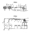
- FIG. 3 The whole of a winding machine of a multi-layer coil for transformer according to embodiment 2 is schematically illustrated in plan view form in Fig. 3 and its front view is illustrated in Fig. 4 .
- Fig. 4 overlapped plural flat-type electric wires are applied with taping so as not to be displaced mutually and then piled up in laminated form to fabricate a multi-layer coil of plural wires.
- a plurality of flat-type electric wires 1A and 1B are set in feeders 12A and 12B, respectively, and they are independently paid out of the feeders 12A and 12B.
- the flat-type electric wires 1A and 1B are passed through a leveler 5 so that a tendency toward curling each of the flat-type electric wires 1A and 1B has been eliminated and thereafter, they are put together in the machine to provide an assemblage 1 of the overlapped plural flat-type electric wires.
- a tape supply and apply unit 3 instantaneously attaches a tape 7 for flat-type electric wire constraint to the bottom of the lowermost flat-type electric wire 1A.
- the flat-type electric wire constraint tape 7 is wound around the flat-type electric wire 1 by use of a unit 4 for attachment of the side and top surfaces of the tape, thereby constraining the overlapped condition of flat-type electric wires 1A and 1B. Thereafter, an assemblage 1 of the flat-type electric wires is sent to a molding unit 10 by means of a conveyance unit 6. Through rolling, the molding unit 10 operates to mold wire portions which constitute curved portions when the flat-type electric wire 1 will be coiled in disk-like form. The thus rolled and molded flat-type electric wire 1 is piled up in laminated form while being coiled in disk-like form by means of a stacking unit 11. It will be appreciated that the flat-type electric wire constrain tape 7 can be made of the same material as the paper which has already been used for fixing the coil for transformer, and of course it meets a test of characteristics required for molding.
- the flat-type wire constraint tape 7 provides an expedient for constraining the overlapped condition of the plural flat-type electric wires 1A and 1B and the tape supply and apply unit 3 acts as a constraint expedient application unit.
- the molding unit 10 and stacking unit 11 can be materialized with those disclosed in the aforementioned Patent Document 1, respectively.
- the molding unit 10 and the stacking unit 11 operate cooperatively with each other to simultaneously mold the flat-type electric wires 1A and 1B of the same shape and same size as if they were a single flat-type electric wire and to pile them up in laminated form while coiling them in disk-like form.
- a flat-type electric wire 1A paid out of the feeder 12A (see Fig. 1 ) and a flat-type electric wire 1B paid out of the feeder 12B (see Fig. 1 ) are underlying and overlying, respectively, in overlapped condition and are mechanically coupled with each other by use of a caulking unit 20.
- the caulking unit 20 has a lower die 21 with a raised part 23 and an upper die 22 with a flat surface 24 confronting the raised part 23.
- the overlapped flat-type electric wires 1A and 1B are clamped together and pressed by the lower and upper dies 21 and 22 so that a raised portion 25 on the top of flat-type electric wire 1A may be fitted in a recessed portion 26 on the bottom of flat-type electric wire 1B, thus fixing both the flat-type electric wires 1A and 1B in a caulk fashion.
- a fitting 27 of raised portion 25 of flat-type wire 1A and recessed portion 26 of flat-type wire 1B in the overlapped condition of flat-type electric wires 1A and 1B provides a constraint expedient for preventing the flat-type electric wires 1A and 1B from displacing mutually, especially, in their longitudinal direction and the caulk unit 20 acts as a unit for applying the constraint expedient.
- Figs. 6A and 6B examples of the multi-layer coil of plural wires for transformer are illustrated in perspective view form. Shown in Fig. 6A is a multi-layer coil coiled in disk-like form to provide a rectangular coil in plan view and shown in Fig. 6B is a multi-layer coil coiled in disk-like form to provide a circular coil in plan view.
- a flat-type electric wire 1 is shown as having overlapped flat-type electric wires 1A and 1B which are mutually bonded by a bonding agent or which are constrained by means of a mechanical raise/recess fitting such as caulking.
- Both the electric wires 1A and 1B are constrained as if they were a single flat-type electric wire and can be coiled in disk-like form as in the case of disk-like coiling of the single flat-type electric wire without taking care of possible disassembling.
- the height of the multi-layer coil of flat-type electric wire 1 is indicated by reference numeral 8 or 9.
- Figs. 7A and 7B there are illustrated, in perspective view, examples of a multi-layer coil of plural wires for transformer having overlapped flat-type electric wires which are constrained by use of the flat-type electric wire constraint tape 7 and are piled up in laminated form.
- the flat-type electric wire constraint tape 7 is as thin as possible because it is responsible for increasing height 8A or 9A of the flat-type wire to be piled up in laminated form. But if application of the flat-type electric wire constraint tapes 7 is concentrated to the same coiling phase position (in the figure, 4 coiling phase positions), the pile-up height 8A or 9A of the flat-type electric wire 1 increases, raising a problem that the coil height increases.
- fabricating proceeds while controlling the position where the flat-type electric wire constraint tape 7 is attached by means of the tape supply and apply unit 3 in such a manner that when the flat-type electric wire 1 is piled up in laminated form by the stacking unit 11, the flat-type electric wire constraint tapes 7 are not concentrated to the same coiling phase position across respective turns of disk-like coiling as shown in Figs. 8A and 8B . In this manner, the pile-up height 8B or 9B of flat-type electric wire 1 can be suppressed as small as permissible.
- the flat-type electric wires since at least two flat-type electric wires can be kept in overlapped condition by means of the constraint expedient during coiling them in laminated disk-like form, the flat-type electric wires will not be disassembled in the stacking unit but are molded as if they were a single flat-type electric wire and then are coiled in disk-like form and piled up in laminated form. Due to the fact that the plural flat-type wires are mutually constrained inside the winding machine, the present invention is advantageous over the prior art when taking preparatory arrangements into account and besides, operation disturbance, for example, stoppage of normal winding operation as required in case the plural flat-type electric wires are desired to be constrained in the course of operation of the winding machine will not occur.
- the flat-type electric wires do not displace mutually when two or more electric wires in combination are molded and piled up in laminated form, a multi-layer coil meeting a transformer of large capacity can be manufactured and besides, by performing constraint of the plural flat-type wires in-line process, coiling can be achieved with time and labor similar to that for a single wire and so a multi-layer coil of plural electric wires and a transformer using the same can be manufactured more inexpensively.
Landscapes
- Engineering & Computer Science (AREA)
- Power Engineering (AREA)
- Manufacturing & Machinery (AREA)
- Coils Of Transformers For General Uses (AREA)
Claims (13)
- Wickelmaschine zum Wickeln einer mehrlagigen Spule für einen Transformator, aufweisend:einen Zuführer (12A, 12B) zum Zuführen eines elektrischen Flachdrahts (1A, 1B), wobei der Zuführer Bestandteil mehrerer Zuführer (12A, 12B) zum entsprechenden Zuführen mehrerer elektrischer Flachdrähte (1A, 1B) ist,eine Formeinheit (10) zum Formen durch Walzen von Drahtabschnitten, die gekrümmte Bereiche bilden werden, wenn der elektrische Flachdraht scheibenartig gespult wird, undeine Stapeleinheit (11) zum scheibenartigen Spulen des von der Formeinheit geformten elektrischen Flachdrahts und zum Aufstapeln der Scheiben in laminierter Form,dadurch gekennzeichnet, dassdie Wickelmaschine eingerichtet ist, die mehreren elektrischen Flachdrähte von den Zuführern in überlappendem Zustand zusammenzuhalten, in dem sie über- und untereinander liegen, sodass die Formeinheit (10) die überlappenden mehreren elektrischen Flachdrähte gleichzeitig formt, während sie im überlappenden Zustand zusammengehalten werden, und dass die Stapeleinheit (11) die zusammengehaltenen und geformten mehreren elektrischen Flachdrähte scheibenartig spult und die Scheiben in laminierter Form aufstapelt.
- Wickelmaschine nach Anspruch 1, die zum gegenseitigen Zusammenhalten der mehreren elektrischen Flachdrähte (1A, 1B) in überlappendem Zustand mittels eines Bands (7) eingerichtet ist, das in Intervallen mit vorbestimmten Abständen in Längsrichtung um sie gewickelt ist.
- Wickelmaschine nach Anspruch 1, die zum gegenseitigen Zusammenhalten der mehreren elektrischen Flachdrähte (1A, 1B) in überlappendem Zustand mittels eines Haftmittels eingerichtet ist, das von einem Haftmittel-Beschichtungsmechanismus (2) in Intervallen mit vorbestimmten Abständen in Längsrichtung aufgebracht wird.
- Wickelmaschine nach Anspruch 1, die zum gegenseitigen Zusammenhalten der mehreren elektrischen Flachdrähte (1A, 1B) in überlappendem Zustand durch mechanische Verbindung wie beispielsweise durch eine Erhebungs-/Vertiefungsbefestigung (27) eingerichtet ist, die in Intervallen von vorbestimmten Abständen in Längsrichtung vorgenommen wird.
- Wickelmaschine nach einem der Ansprüche 1 bis 4, die zum Zusammenhalten des überlappenden Zustands an Zusammenhalteorten eingerichtet ist, die in Umfangsrichtung entlang entsprechender Windungen des scheibenartigen Spulens unterschiedlich verteilt sind.
- Wickelmaschine nach einem der Ansprüche 1 bis 5, die zum Aufstapeln der mehreren elektrischen Flachdrähte (1A, 1B) in laminierter Form eingerichtet ist, während diese scheibenartig unter Bildung einer kreisförmigen oder einer rechteckigen mehrlagigen Spule gespult werden.
- Mehrlagige Spule aus mehreren Drähten für einen Transformator, die elektrische Flachdrähte umfasst, die einander überlappen, sodass sie über- und untereinander liegen,
gekennzeichnet durch ein Zusammenhaltemittel (7; 25, 26, 27), das mehrere der elektrischen Flachdrähte (1A, 1B) in überlappendem Zustand gegen einen örtlichen Versatz zwischen ihnen so beieinander zusammenhält, als ob sie ein einzelner elektrischer Flachdraht (1) wären, wobei der einzelne elektrische Flachdraht (1) mit dem Zusammenhaltemittel scheibenartig gespult ist und die Scheiben in laminierter Form aufgestapelt sind, sodass sie die mehrlagige Spule aus mehreren Drähten (1A, 1B) bilden. - Mehrlagige Spule nach Anspruch 7, dadurch gekennzeichnet, dass das Zusammenhaltemittel ein Band (7) umfasst, das um die mehreren elektrischen Flachdrähte (1A, 1B) in bestimmten Intervallen mit Abständen in Längsrichtung gewickelt ist.
- Mehrlagige Spule nach Anspruch 7, dadurch gekennzeichnet, dass das Zusammenhaltemittel ein Haftmittel umfasst, das in vorbestimmten Intervallen mit Abständen in Längsrichtung der mehreren elektrischen Flachdrähte (1A, 1B) aufgebracht ist.
- Mehrlagige Spule nach Anspruch 7, dadurch gekennzeichnet, dass das Zusammenhaltemittel eine mechanische Verbindung wie beispielsweise eine Erhebungs-/Vertiefungsbefestigung (27) umfasst, die in vorbestimmten Intervallen mit Abständen in Längsrichtung der mehreren elektrischen Flachdrähte (1A, 1B) angebracht ist.
- Mehrlagige Spule nach einem der Ansprüche 7 bis 10, dadurch gekennzeichnet, dass die Zusammenhalteorte, an denen das Zusammenhaltemittel vorgesehen ist, in Umfangsrichtung entlang entsprechender Windungen der scheibenartigen Spulung unterschiedlich verteilt sind.
- Mehrlagige Spule nach einem der Ansprüche 7 bis 11, dadurch gekennzeichnet, dass die mehrlagige Spule eine kreisförmige oder eine rechtwinklige mehrlagige Spule ist.
- Wickelverfahren zum Wickeln einer mehrlagigen Spule für einen Transformator mit folgenden Schritten:entsprechendes Zuführen mehrerer elektrischer Flachdrähte (1A, 1B) durch mehrere Zuführer (12A, 12B),Formen durch Walzen und mittels einer Formeinheit (10) von Drahtabschnitten, die gekrümmte Abschnitte bilden werden, wenn die elektrischen Flachdrähte scheibenartig gespult werden, undscheibenartiges Spulen der von der Formeinheit geformten elektrischen Flachdrähte und Aufstapeln der Scheiben in laminierter Form mittels einer Stapeleinheit (11),gekennzeichnet durchZusammenhalten der mehreren elektrischen Flachdrähte von den Zuführern in überlappendem Zustand, in dem sie über- und untereinander liegen, sodass die Formeinheit (10) im Formschritt die überlappenden mehreren elektrischen Flachdrähte gleichzeitig formt, während sie in überlappendem Zustand zusammengehalten werden, und die Stapeleinheit (11) im Spul- und Stapelschritt die zusammengehaltenen und geformten mehreren elektrischen Flachdrähte scheibenartig spult und die Scheiben in laminierter Form aufstapelt.
Applications Claiming Priority (1)
| Application Number | Priority Date | Filing Date | Title |
|---|---|---|---|
| JP2009090142A JP5172767B2 (ja) | 2009-04-02 | 2009-04-02 | 変圧器用複数線多段コイルの巻線装置 |
Publications (3)
| Publication Number | Publication Date |
|---|---|
| EP2237291A2 EP2237291A2 (de) | 2010-10-06 |
| EP2237291A3 EP2237291A3 (de) | 2013-03-27 |
| EP2237291B1 true EP2237291B1 (de) | 2015-12-23 |
Family
ID=42299181
Family Applications (1)
| Application Number | Title | Priority Date | Filing Date |
|---|---|---|---|
| EP10000359.9A Not-in-force EP2237291B1 (de) | 2009-04-02 | 2010-01-15 | Mehrschichtige Spule mit mehreren elektrischen Drähten für Transformator und deren Wickelmaschine |
Country Status (3)
| Country | Link |
|---|---|
| EP (1) | EP2237291B1 (de) |
| JP (1) | JP5172767B2 (de) |
| CN (2) | CN102768900A (de) |
Families Citing this family (12)
| Publication number | Priority date | Publication date | Assignee | Title |
|---|---|---|---|---|
| JP5838921B2 (ja) * | 2012-06-21 | 2016-01-06 | Fcm株式会社 | コイル |
| WO2015121943A1 (ja) * | 2014-02-13 | 2015-08-20 | 株式会社日立産機システム | 変圧器用複数線多段コイルの巻線方法、及び変圧器用複数線多段コイル |
| JP6379689B2 (ja) * | 2014-06-03 | 2018-08-29 | 株式会社デンソー | コイル装置およびコイル装置の製造方法 |
| JP6463128B2 (ja) * | 2014-12-26 | 2019-01-30 | オリンパス株式会社 | 接続構造及び接続方法 |
| KR101673030B1 (ko) * | 2015-07-01 | 2016-11-04 | 산일전기 주식회사 | 변압기용 코어 조립체와 그 제조 방법 |
| KR101673029B1 (ko) * | 2015-07-01 | 2016-11-04 | 산일전기 주식회사 | 테이핑 장치 및 변압기용 코어 조립체의 제조장치 |
| KR101771105B1 (ko) * | 2015-10-23 | 2017-08-24 | 주식회사 톰스코 | 로터리형 평면코일안테나 스마트 자동제작장치 |
| US10998124B2 (en) | 2016-05-06 | 2021-05-04 | Vishay Dale Electronics, Llc | Nested flat wound coils forming windings for transformers and inductors |
| DE102017207660A1 (de) * | 2017-05-08 | 2018-11-08 | Audi Ag | Verfahren zur Herstellung einer Spule |
| JP7198396B2 (ja) * | 2017-12-28 | 2023-01-04 | 株式会社セキデン | 中空芯コイル及びその製造方法 |
| CN109545540B (zh) * | 2018-10-29 | 2020-12-15 | 东莞市智感机械电子科技有限公司 | 全自动多线绕线机 |
| JP7064108B1 (ja) | 2021-09-08 | 2022-05-10 | 田中精密工業株式会社 | モータ巻線製造方法及びモータ巻線製造装置 |
Family Cites Families (18)
| Publication number | Priority date | Publication date | Assignee | Title |
|---|---|---|---|---|
| JPS5516436A (en) * | 1978-07-24 | 1980-02-05 | Hitachi Ltd | Producing method of coil |
| JPS55117223A (en) * | 1979-03-01 | 1980-09-09 | Sumitomo Electric Ind Ltd | Coiling method of pulse transformer or the like |
| JPS587309A (ja) * | 1981-07-03 | 1983-01-17 | 大建工業株式会社 | 化粧材の製造方法 |
| JPS5992508A (ja) * | 1982-11-19 | 1984-05-28 | Toshiba Corp | エツジワイズコイルの製造方法 |
| US4484974A (en) * | 1983-06-27 | 1984-11-27 | Loral Corporation | Multiple layer coil winding system |
| US5174013A (en) * | 1988-06-16 | 1992-12-29 | Nippondenso Co., Ltd. | Winding apparatus and method which deforms the wire during winding |
| JPH0453109A (ja) * | 1990-06-18 | 1992-02-20 | Toshiba Corp | 樹脂モールドコイル |
| JP2682587B2 (ja) * | 1991-09-26 | 1997-11-26 | 三菱電機株式会社 | 巻線形成方法および巻線形成装置 |
| JPH0653067A (ja) * | 1992-07-28 | 1994-02-25 | Toshiba Corp | モールドコイルの製造方法 |
| JP3157735B2 (ja) * | 1997-02-20 | 2001-04-16 | 北陸電機製造株式会社 | コイルとその製造方法 |
| JP3560818B2 (ja) * | 1998-06-26 | 2004-09-02 | ティーエム・ティーアンドディー株式会社 | テープ巻平角導体の案内装置及び複合テープ巻装置 |
| JP2003017328A (ja) * | 2001-06-28 | 2003-01-17 | Tabuchi Electric Co Ltd | 平角線を用いたインダクタンス素子 |
| JP3996005B2 (ja) * | 2002-07-18 | 2007-10-24 | 株式会社日立産機システム | 多段コイル製作装置 |
| JP4448372B2 (ja) * | 2004-04-27 | 2010-04-07 | 株式会社日立産機システム | モールド変圧器の製造方法 |
| JP4616652B2 (ja) * | 2005-01-13 | 2011-01-19 | 株式会社日立産機システム | コイル製造装置 |
| JP2006344435A (ja) * | 2005-06-07 | 2006-12-21 | Mosutetsuku:Kk | 線材、コイル、ステータコイル、ロータコイル、及び変成器 |
| JP2007173263A (ja) * | 2005-12-19 | 2007-07-05 | Selco Co Ltd | エッジワイズ巻電磁コイル及び製造方法 |
| DE102007022171B4 (de) * | 2007-05-11 | 2009-12-10 | Siemens Ag | Vorrichtung zum Aufbringen von Leiterdrähten auf einen Träger |
-
2009
- 2009-04-02 JP JP2009090142A patent/JP5172767B2/ja active Active
-
2010
- 2010-01-15 EP EP10000359.9A patent/EP2237291B1/de not_active Not-in-force
- 2010-01-25 CN CN2012102280239A patent/CN102768900A/zh active Pending
- 2010-01-25 CN CN2010101054496A patent/CN101859636B/zh not_active Expired - Fee Related
Also Published As
| Publication number | Publication date |
|---|---|
| CN101859636B (zh) | 2013-02-13 |
| EP2237291A3 (de) | 2013-03-27 |
| JP2010245169A (ja) | 2010-10-28 |
| CN101859636A (zh) | 2010-10-13 |
| JP5172767B2 (ja) | 2013-03-27 |
| EP2237291A2 (de) | 2010-10-06 |
| CN102768900A (zh) | 2012-11-07 |
Similar Documents
| Publication | Publication Date | Title |
|---|---|---|
| EP2237291A2 (de) | Mehrschichtige Spule mit mehreren elektrischen Drähten für Transformator und deren Wickelmaschine | |
| CN101925970B (zh) | 变压器及其卷绕铁芯的制造装置和制造方法 | |
| US5261152A (en) | Method for manufacturing amorphous magnetic core | |
| US7948347B2 (en) | Multi-stage coil for transformer, and coil winding method and apparatus for manufacturing the same | |
| KR101657867B1 (ko) | 에지 와이즈 코일 권선 방법 및 권선 장치 | |
| CN104425836A (zh) | 卷绕装置和卷绕元件的制造方法 | |
| CN112534525B (zh) | 具有间隔板的多重平行导体 | |
| JP4581188B2 (ja) | 平角線構造及び平角線の巻線方法 | |
| RU2611723C2 (ru) | Катушка, установка для изготовления катушки и способ изготовления катушки | |
| CN108987084B (zh) | 带供给方法和系统以及用于生产变压器的叠片铁芯的设备 | |
| JP5555933B2 (ja) | 巻線の製造方法及び製造装置 | |
| JP2018098407A (ja) | 巻線及びその製造装置、並びに巻線の製造方法 | |
| JP6646333B2 (ja) | 打抜き加工方法および積層鉄心の製造方法 | |
| JP5252379B2 (ja) | リアクトル用コイルの製造方法 | |
| JP6510985B2 (ja) | 変圧器用複数線多段コイルの巻線方法、及び変圧器用複数線多段コイル | |
| US743779A (en) | Process of winding electrical coils. | |
| KR102086395B1 (ko) | 변류기 직사각형 코아 권취 자동제작 시스템 및 그 변류기 권취 환형코아 자동 제작 시스템 운용방법 | |
| CN105321700A (zh) | 用于制造多层磁芯的方法 | |
| JPH09237727A (ja) | アモルファス鉄心製造方法及びその装置 | |
| JP2011120355A (ja) | 積層コア製造装置および積層コア製造方法 | |
| JPH10270263A (ja) | アモルファス変圧器 | |
| JPH03211712A (ja) | アモルファス鉄心とその製造法 | |
| JP2019009302A (ja) | 巻鉄心の製造装置、巻鉄心の製造方法 | |
| KR200247924Y1 (ko) | 철사의 제조장치 | |
| KR100428739B1 (ko) | 철사의 제조방법 및 그 장치 |
Legal Events
| Date | Code | Title | Description |
|---|---|---|---|
| PUAI | Public reference made under article 153(3) epc to a published international application that has entered the european phase |
Free format text: ORIGINAL CODE: 0009012 |
|
| 17P | Request for examination filed |
Effective date: 20100331 |
|
| AK | Designated contracting states |
Kind code of ref document: A2 Designated state(s): AT BE BG CH CY CZ DE DK EE ES FI FR GB GR HR HU IE IS IT LI LT LU LV MC MK MT NL NO PL PT RO SE SI SK SM TR |
|
| AX | Request for extension of the european patent |
Extension state: AL BA RS |
|
| PUAL | Search report despatched |
Free format text: ORIGINAL CODE: 0009013 |
|
| AK | Designated contracting states |
Kind code of ref document: A3 Designated state(s): AT BE BG CH CY CZ DE DK EE ES FI FR GB GR HR HU IE IS IT LI LT LU LV MC MK MT NL NO PL PT RO SE SI SK SM TR |
|
| AX | Request for extension of the european patent |
Extension state: AL BA RS |
|
| RIC1 | Information provided on ipc code assigned before grant |
Ipc: H01F 41/06 20060101AFI20130215BHEP Ipc: H01F 27/28 20060101ALI20130215BHEP |
|
| 17Q | First examination report despatched |
Effective date: 20131029 |
|
| GRAP | Despatch of communication of intention to grant a patent |
Free format text: ORIGINAL CODE: EPIDOSNIGR1 |
|
| INTG | Intention to grant announced |
Effective date: 20141124 |
|
| GRAS | Grant fee paid |
Free format text: ORIGINAL CODE: EPIDOSNIGR3 |
|
| GRAP | Despatch of communication of intention to grant a patent |
Free format text: ORIGINAL CODE: EPIDOSNIGR1 |
|
| INTG | Intention to grant announced |
Effective date: 20150625 |
|
| GRAA | (expected) grant |
Free format text: ORIGINAL CODE: 0009210 |
|
| AK | Designated contracting states |
Kind code of ref document: B1 Designated state(s): AT BE BG CH CY CZ DE DK EE ES FI FR GB GR HR HU IE IS IT LI LT LU LV MC MK MT NL NO PL PT RO SE SI SK SM TR |
|
| REG | Reference to a national code |
Ref country code: GB Ref legal event code: FG4D |
|
| REG | Reference to a national code |
Ref country code: CH Ref legal event code: EP |
|
| REG | Reference to a national code |
Ref country code: IE Ref legal event code: FG4D |
|
| REG | Reference to a national code |
Ref country code: AT Ref legal event code: REF Ref document number: 766859 Country of ref document: AT Kind code of ref document: T Effective date: 20160115 |
|
| REG | Reference to a national code |
Ref country code: DE Ref legal event code: R096 Ref document number: 602010029625 Country of ref document: DE |
|
| REG | Reference to a national code |
Ref country code: LT Ref legal event code: MG4D |
|
| REG | Reference to a national code |
Ref country code: NL Ref legal event code: MP Effective date: 20151223 |
|
| PG25 | Lapsed in a contracting state [announced via postgrant information from national office to epo] |
Ref country code: NO Free format text: LAPSE BECAUSE OF FAILURE TO SUBMIT A TRANSLATION OF THE DESCRIPTION OR TO PAY THE FEE WITHIN THE PRESCRIBED TIME-LIMIT Effective date: 20160323 Ref country code: LT Free format text: LAPSE BECAUSE OF FAILURE TO SUBMIT A TRANSLATION OF THE DESCRIPTION OR TO PAY THE FEE WITHIN THE PRESCRIBED TIME-LIMIT Effective date: 20151223 Ref country code: HR Free format text: LAPSE BECAUSE OF FAILURE TO SUBMIT A TRANSLATION OF THE DESCRIPTION OR TO PAY THE FEE WITHIN THE PRESCRIBED TIME-LIMIT Effective date: 20151223 |
|
| REG | Reference to a national code |
Ref country code: AT Ref legal event code: MK05 Ref document number: 766859 Country of ref document: AT Kind code of ref document: T Effective date: 20151223 |
|
| PG25 | Lapsed in a contracting state [announced via postgrant information from national office to epo] |
Ref country code: NL Free format text: LAPSE BECAUSE OF FAILURE TO SUBMIT A TRANSLATION OF THE DESCRIPTION OR TO PAY THE FEE WITHIN THE PRESCRIBED TIME-LIMIT Effective date: 20151223 Ref country code: BE Free format text: LAPSE BECAUSE OF NON-PAYMENT OF DUE FEES Effective date: 20160131 Ref country code: GR Free format text: LAPSE BECAUSE OF FAILURE TO SUBMIT A TRANSLATION OF THE DESCRIPTION OR TO PAY THE FEE WITHIN THE PRESCRIBED TIME-LIMIT Effective date: 20160324 Ref country code: FI Free format text: LAPSE BECAUSE OF FAILURE TO SUBMIT A TRANSLATION OF THE DESCRIPTION OR TO PAY THE FEE WITHIN THE PRESCRIBED TIME-LIMIT Effective date: 20151223 Ref country code: SE Free format text: LAPSE BECAUSE OF FAILURE TO SUBMIT A TRANSLATION OF THE DESCRIPTION OR TO PAY THE FEE WITHIN THE PRESCRIBED TIME-LIMIT Effective date: 20151223 Ref country code: LV Free format text: LAPSE BECAUSE OF FAILURE TO SUBMIT A TRANSLATION OF THE DESCRIPTION OR TO PAY THE FEE WITHIN THE PRESCRIBED TIME-LIMIT Effective date: 20151223 |
|
| PG25 | Lapsed in a contracting state [announced via postgrant information from national office to epo] |
Ref country code: CZ Free format text: LAPSE BECAUSE OF FAILURE TO SUBMIT A TRANSLATION OF THE DESCRIPTION OR TO PAY THE FEE WITHIN THE PRESCRIBED TIME-LIMIT Effective date: 20151223 Ref country code: IT Free format text: LAPSE BECAUSE OF FAILURE TO SUBMIT A TRANSLATION OF THE DESCRIPTION OR TO PAY THE FEE WITHIN THE PRESCRIBED TIME-LIMIT Effective date: 20151223 Ref country code: ES Free format text: LAPSE BECAUSE OF FAILURE TO SUBMIT A TRANSLATION OF THE DESCRIPTION OR TO PAY THE FEE WITHIN THE PRESCRIBED TIME-LIMIT Effective date: 20151223 |
|
| PG25 | Lapsed in a contracting state [announced via postgrant information from national office to epo] |
Ref country code: LU Free format text: LAPSE BECAUSE OF FAILURE TO SUBMIT A TRANSLATION OF THE DESCRIPTION OR TO PAY THE FEE WITHIN THE PRESCRIBED TIME-LIMIT Effective date: 20160115 Ref country code: AT Free format text: LAPSE BECAUSE OF FAILURE TO SUBMIT A TRANSLATION OF THE DESCRIPTION OR TO PAY THE FEE WITHIN THE PRESCRIBED TIME-LIMIT Effective date: 20151223 Ref country code: SK Free format text: LAPSE BECAUSE OF FAILURE TO SUBMIT A TRANSLATION OF THE DESCRIPTION OR TO PAY THE FEE WITHIN THE PRESCRIBED TIME-LIMIT Effective date: 20151223 Ref country code: EE Free format text: LAPSE BECAUSE OF FAILURE TO SUBMIT A TRANSLATION OF THE DESCRIPTION OR TO PAY THE FEE WITHIN THE PRESCRIBED TIME-LIMIT Effective date: 20151223 Ref country code: PT Free format text: LAPSE BECAUSE OF FAILURE TO SUBMIT A TRANSLATION OF THE DESCRIPTION OR TO PAY THE FEE WITHIN THE PRESCRIBED TIME-LIMIT Effective date: 20160426 Ref country code: PL Free format text: LAPSE BECAUSE OF FAILURE TO SUBMIT A TRANSLATION OF THE DESCRIPTION OR TO PAY THE FEE WITHIN THE PRESCRIBED TIME-LIMIT Effective date: 20151223 Ref country code: SM Free format text: LAPSE BECAUSE OF FAILURE TO SUBMIT A TRANSLATION OF THE DESCRIPTION OR TO PAY THE FEE WITHIN THE PRESCRIBED TIME-LIMIT Effective date: 20151223 Ref country code: IS Free format text: LAPSE BECAUSE OF FAILURE TO SUBMIT A TRANSLATION OF THE DESCRIPTION OR TO PAY THE FEE WITHIN THE PRESCRIBED TIME-LIMIT Effective date: 20160423 Ref country code: RO Free format text: LAPSE BECAUSE OF FAILURE TO SUBMIT A TRANSLATION OF THE DESCRIPTION OR TO PAY THE FEE WITHIN THE PRESCRIBED TIME-LIMIT Effective date: 20151223 |
|
| REG | Reference to a national code |
Ref country code: CH Ref legal event code: PL |
|
| REG | Reference to a national code |
Ref country code: DE Ref legal event code: R097 Ref document number: 602010029625 Country of ref document: DE |
|
| PG25 | Lapsed in a contracting state [announced via postgrant information from national office to epo] |
Ref country code: MC Free format text: LAPSE BECAUSE OF FAILURE TO SUBMIT A TRANSLATION OF THE DESCRIPTION OR TO PAY THE FEE WITHIN THE PRESCRIBED TIME-LIMIT Effective date: 20151223 |
|
| PLBE | No opposition filed within time limit |
Free format text: ORIGINAL CODE: 0009261 |
|
| REG | Reference to a national code |
Ref country code: FR Ref legal event code: ST Effective date: 20160930 |
|
| STAA | Information on the status of an ep patent application or granted ep patent |
Free format text: STATUS: NO OPPOSITION FILED WITHIN TIME LIMIT |
|
| PG25 | Lapsed in a contracting state [announced via postgrant information from national office to epo] |
Ref country code: LI Free format text: LAPSE BECAUSE OF NON-PAYMENT OF DUE FEES Effective date: 20160131 Ref country code: DK Free format text: LAPSE BECAUSE OF FAILURE TO SUBMIT A TRANSLATION OF THE DESCRIPTION OR TO PAY THE FEE WITHIN THE PRESCRIBED TIME-LIMIT Effective date: 20151223 Ref country code: CH Free format text: LAPSE BECAUSE OF NON-PAYMENT OF DUE FEES Effective date: 20160131 |
|
| REG | Reference to a national code |
Ref country code: IE Ref legal event code: MM4A |
|
| GBPC | Gb: european patent ceased through non-payment of renewal fee |
Effective date: 20160323 |
|
| 26N | No opposition filed |
Effective date: 20160926 |
|
| PG25 | Lapsed in a contracting state [announced via postgrant information from national office to epo] |
Ref country code: FR Free format text: LAPSE BECAUSE OF NON-PAYMENT OF DUE FEES Effective date: 20160223 |
|
| PG25 | Lapsed in a contracting state [announced via postgrant information from national office to epo] |
Ref country code: BE Free format text: LAPSE BECAUSE OF FAILURE TO SUBMIT A TRANSLATION OF THE DESCRIPTION OR TO PAY THE FEE WITHIN THE PRESCRIBED TIME-LIMIT Effective date: 20151223 |
|
| PG25 | Lapsed in a contracting state [announced via postgrant information from national office to epo] |
Ref country code: IE Free format text: LAPSE BECAUSE OF NON-PAYMENT OF DUE FEES Effective date: 20160115 Ref country code: GB Free format text: LAPSE BECAUSE OF NON-PAYMENT OF DUE FEES Effective date: 20160323 |
|
| PG25 | Lapsed in a contracting state [announced via postgrant information from national office to epo] |
Ref country code: SI Free format text: LAPSE BECAUSE OF FAILURE TO SUBMIT A TRANSLATION OF THE DESCRIPTION OR TO PAY THE FEE WITHIN THE PRESCRIBED TIME-LIMIT Effective date: 20151223 |
|
| PGFP | Annual fee paid to national office [announced via postgrant information from national office to epo] |
Ref country code: DE Payment date: 20170110 Year of fee payment: 8 |
|
| PG25 | Lapsed in a contracting state [announced via postgrant information from national office to epo] |
Ref country code: MT Free format text: LAPSE BECAUSE OF FAILURE TO SUBMIT A TRANSLATION OF THE DESCRIPTION OR TO PAY THE FEE WITHIN THE PRESCRIBED TIME-LIMIT Effective date: 20151223 |
|
| PG25 | Lapsed in a contracting state [announced via postgrant information from national office to epo] |
Ref country code: HU Free format text: LAPSE BECAUSE OF FAILURE TO SUBMIT A TRANSLATION OF THE DESCRIPTION OR TO PAY THE FEE WITHIN THE PRESCRIBED TIME-LIMIT; INVALID AB INITIO Effective date: 20100115 Ref country code: CY Free format text: LAPSE BECAUSE OF FAILURE TO SUBMIT A TRANSLATION OF THE DESCRIPTION OR TO PAY THE FEE WITHIN THE PRESCRIBED TIME-LIMIT Effective date: 20151223 |
|
| PG25 | Lapsed in a contracting state [announced via postgrant information from national office to epo] |
Ref country code: MK Free format text: LAPSE BECAUSE OF FAILURE TO SUBMIT A TRANSLATION OF THE DESCRIPTION OR TO PAY THE FEE WITHIN THE PRESCRIBED TIME-LIMIT Effective date: 20151223 Ref country code: TR Free format text: LAPSE BECAUSE OF FAILURE TO SUBMIT A TRANSLATION OF THE DESCRIPTION OR TO PAY THE FEE WITHIN THE PRESCRIBED TIME-LIMIT Effective date: 20151223 Ref country code: MT Free format text: LAPSE BECAUSE OF FAILURE TO SUBMIT A TRANSLATION OF THE DESCRIPTION OR TO PAY THE FEE WITHIN THE PRESCRIBED TIME-LIMIT Effective date: 20160131 |
|
| PG25 | Lapsed in a contracting state [announced via postgrant information from national office to epo] |
Ref country code: BG Free format text: LAPSE BECAUSE OF FAILURE TO SUBMIT A TRANSLATION OF THE DESCRIPTION OR TO PAY THE FEE WITHIN THE PRESCRIBED TIME-LIMIT Effective date: 20151223 |
|
| REG | Reference to a national code |
Ref country code: DE Ref legal event code: R119 Ref document number: 602010029625 Country of ref document: DE |
|
| PG25 | Lapsed in a contracting state [announced via postgrant information from national office to epo] |
Ref country code: DE Free format text: LAPSE BECAUSE OF NON-PAYMENT OF DUE FEES Effective date: 20180801 |