EP2230732A1 - Dispositif de butée d'une ligne sur un élément de liaison - Google Patents
Dispositif de butée d'une ligne sur un élément de liaison Download PDFInfo
- Publication number
- EP2230732A1 EP2230732A1 EP09003761A EP09003761A EP2230732A1 EP 2230732 A1 EP2230732 A1 EP 2230732A1 EP 09003761 A EP09003761 A EP 09003761A EP 09003761 A EP09003761 A EP 09003761A EP 2230732 A1 EP2230732 A1 EP 2230732A1
- Authority
- EP
- European Patent Office
- Prior art keywords
- recess
- lower die
- connecting element
- die
- upper die
- Prior art date
- Legal status (The legal status is an assumption and is not a legal conclusion. Google has not performed a legal analysis and makes no representation as to the accuracy of the status listed.)
- Granted
Links
Images

Classifications
-
- H—ELECTRICITY
- H01—ELECTRIC ELEMENTS
- H01R—ELECTRICALLY-CONDUCTIVE CONNECTIONS; STRUCTURAL ASSOCIATIONS OF A PLURALITY OF MUTUALLY-INSULATED ELECTRICAL CONNECTING ELEMENTS; COUPLING DEVICES; CURRENT COLLECTORS
- H01R43/00—Apparatus or processes specially adapted for manufacturing, assembling, maintaining, or repairing of line connectors or current collectors or for joining electric conductors
- H01R43/04—Apparatus or processes specially adapted for manufacturing, assembling, maintaining, or repairing of line connectors or current collectors or for joining electric conductors for forming connections by deformation, e.g. crimping tool
- H01R43/058—Crimping mandrels
-
- H—ELECTRICITY
- H01—ELECTRIC ELEMENTS
- H01R—ELECTRICALLY-CONDUCTIVE CONNECTIONS; STRUCTURAL ASSOCIATIONS OF A PLURALITY OF MUTUALLY-INSULATED ELECTRICAL CONNECTING ELEMENTS; COUPLING DEVICES; CURRENT COLLECTORS
- H01R4/00—Electrically-conductive connections between two or more conductive members in direct contact, i.e. touching one another; Means for effecting or maintaining such contact; Electrically-conductive connections having two or more spaced connecting locations for conductors and using contact members penetrating insulation
- H01R4/10—Electrically-conductive connections between two or more conductive members in direct contact, i.e. touching one another; Means for effecting or maintaining such contact; Electrically-conductive connections having two or more spaced connecting locations for conductors and using contact members penetrating insulation effected solely by twisting, wrapping, bending, crimping, or other permanent deformation
- H01R4/18—Electrically-conductive connections between two or more conductive members in direct contact, i.e. touching one another; Means for effecting or maintaining such contact; Electrically-conductive connections having two or more spaced connecting locations for conductors and using contact members penetrating insulation effected solely by twisting, wrapping, bending, crimping, or other permanent deformation by crimping
- H01R4/183—Electrically-conductive connections between two or more conductive members in direct contact, i.e. touching one another; Means for effecting or maintaining such contact; Electrically-conductive connections having two or more spaced connecting locations for conductors and using contact members penetrating insulation effected solely by twisting, wrapping, bending, crimping, or other permanent deformation by crimping for cylindrical elongated bodies, e.g. cables having circular cross-section
-
- Y—GENERAL TAGGING OF NEW TECHNOLOGICAL DEVELOPMENTS; GENERAL TAGGING OF CROSS-SECTIONAL TECHNOLOGIES SPANNING OVER SEVERAL SECTIONS OF THE IPC; TECHNICAL SUBJECTS COVERED BY FORMER USPC CROSS-REFERENCE ART COLLECTIONS [XRACs] AND DIGESTS
- Y10—TECHNICAL SUBJECTS COVERED BY FORMER USPC
- Y10T—TECHNICAL SUBJECTS COVERED BY FORMER US CLASSIFICATION
- Y10T29/00—Metal working
- Y10T29/49—Method of mechanical manufacture
- Y10T29/49002—Electrical device making
- Y10T29/49117—Conductor or circuit manufacturing
- Y10T29/49124—On flat or curved insulated base, e.g., printed circuit, etc.
- Y10T29/4913—Assembling to base an electrical component, e.g., capacitor, etc.
- Y10T29/49139—Assembling to base an electrical component, e.g., capacitor, etc. by inserting component lead or terminal into base aperture
- Y10T29/4914—Assembling to base an electrical component, e.g., capacitor, etc. by inserting component lead or terminal into base aperture with deforming of lead or terminal
-
- Y—GENERAL TAGGING OF NEW TECHNOLOGICAL DEVELOPMENTS; GENERAL TAGGING OF CROSS-SECTIONAL TECHNOLOGIES SPANNING OVER SEVERAL SECTIONS OF THE IPC; TECHNICAL SUBJECTS COVERED BY FORMER USPC CROSS-REFERENCE ART COLLECTIONS [XRACs] AND DIGESTS
- Y10—TECHNICAL SUBJECTS COVERED BY FORMER USPC
- Y10T—TECHNICAL SUBJECTS COVERED BY FORMER US CLASSIFICATION
- Y10T29/00—Metal working
- Y10T29/49—Method of mechanical manufacture
- Y10T29/49002—Electrical device making
- Y10T29/49117—Conductor or circuit manufacturing
- Y10T29/49174—Assembling terminal to elongated conductor
- Y10T29/49181—Assembling terminal to elongated conductor by deforming
- Y10T29/49183—Assembling terminal to elongated conductor by deforming of ferrule about conductor and terminal
-
- Y—GENERAL TAGGING OF NEW TECHNOLOGICAL DEVELOPMENTS; GENERAL TAGGING OF CROSS-SECTIONAL TECHNOLOGIES SPANNING OVER SEVERAL SECTIONS OF THE IPC; TECHNICAL SUBJECTS COVERED BY FORMER USPC CROSS-REFERENCE ART COLLECTIONS [XRACs] AND DIGESTS
- Y10—TECHNICAL SUBJECTS COVERED BY FORMER USPC
- Y10T—TECHNICAL SUBJECTS COVERED BY FORMER US CLASSIFICATION
- Y10T29/00—Metal working
- Y10T29/49—Method of mechanical manufacture
- Y10T29/49826—Assembling or joining
- Y10T29/49908—Joining by deforming
- Y10T29/49925—Inward deformation of aperture or hollow body wall
-
- Y—GENERAL TAGGING OF NEW TECHNOLOGICAL DEVELOPMENTS; GENERAL TAGGING OF CROSS-SECTIONAL TECHNOLOGIES SPANNING OVER SEVERAL SECTIONS OF THE IPC; TECHNICAL SUBJECTS COVERED BY FORMER USPC CROSS-REFERENCE ART COLLECTIONS [XRACs] AND DIGESTS
- Y10—TECHNICAL SUBJECTS COVERED BY FORMER USPC
- Y10T—TECHNICAL SUBJECTS COVERED BY FORMER US CLASSIFICATION
- Y10T29/00—Metal working
- Y10T29/53—Means to assemble or disassemble
- Y10T29/5313—Means to assemble electrical device
- Y10T29/532—Conductor
- Y10T29/53209—Terminal or connector
- Y10T29/53213—Assembled to wire-type conductor
- Y10T29/53222—Means comprising hand-manipulatable implement
- Y10T29/53226—Fastening by deformation
-
- Y—GENERAL TAGGING OF NEW TECHNOLOGICAL DEVELOPMENTS; GENERAL TAGGING OF CROSS-SECTIONAL TECHNOLOGIES SPANNING OVER SEVERAL SECTIONS OF THE IPC; TECHNICAL SUBJECTS COVERED BY FORMER USPC CROSS-REFERENCE ART COLLECTIONS [XRACs] AND DIGESTS
- Y10—TECHNICAL SUBJECTS COVERED BY FORMER USPC
- Y10T—TECHNICAL SUBJECTS COVERED BY FORMER US CLASSIFICATION
- Y10T29/00—Metal working
- Y10T29/53—Means to assemble or disassemble
- Y10T29/5313—Means to assemble electrical device
- Y10T29/532—Conductor
- Y10T29/53209—Terminal or connector
- Y10T29/53213—Assembled to wire-type conductor
- Y10T29/53235—Means to fasten by deformation
-
- Y—GENERAL TAGGING OF NEW TECHNOLOGICAL DEVELOPMENTS; GENERAL TAGGING OF CROSS-SECTIONAL TECHNOLOGIES SPANNING OVER SEVERAL SECTIONS OF THE IPC; TECHNICAL SUBJECTS COVERED BY FORMER USPC CROSS-REFERENCE ART COLLECTIONS [XRACs] AND DIGESTS
- Y10—TECHNICAL SUBJECTS COVERED BY FORMER USPC
- Y10T—TECHNICAL SUBJECTS COVERED BY FORMER US CLASSIFICATION
- Y10T29/00—Metal working
- Y10T29/53—Means to assemble or disassemble
- Y10T29/5313—Means to assemble electrical device
- Y10T29/5327—Means to fasten by deforming
Definitions
- the present invention relates to an apparatus and method for striking a conduit to a connector.
- the apparatus includes an upper die and a lower die, each having a pressing surface to press the conduit and the connecting member in a predetermined area between the lower die and the upper die.
- Such devices and methods are used for example in electrical connection technology to produce a no longer detachable connection between a line and a connecting element.
- the line and the connecting element are connected to each other by a plastic deformation, which is caused by a pressing force.
- the lead and the connecting element can be further electrically contacted, wherein the connecting element as any contact element, e.g. as a plug can be formed.
- connection between the conductor and the connecting element can be produced for example by crimping or splicing.
- crimping usually preformed fasteners are used whose dimensions, in particular their length, are matched to the cross section of the line.
- crimping tools have predetermined profiles in order to bring about a predeterminable deformation of the line and the connecting element and thereby the crimped connection in one form the desired shape.
- splicing an endless belt is used instead of a preformed connecting element.
- a crimp connection can be produced in the simplest case by means of a crimping tool.
- automated devices are used.
- Such a device is in Fig. 1 shown schematically and includes an upper die, in which engages a stamp-like lower die. The line and the connecting element pass between pressing surfaces of the upper and lower dies and are pressed together by means of a pressing force which is exerted on the upper or lower die.
- the outer shape of the crimped connection is to be defined by the shape of the pressing surfaces of the upper and lower dies, an extremely small gap size is required between the flanks or side surfaces of the upper and lower dies.
- various types of defects may occur in the manufacture of the crimped connection.
- the connecting element may already be deformed before it reaches the device.
- the conduit and the connecting element may be displaced or twisted with respect to a central axis of the upper and lower dies.
- the upper and lower dies can be displaced relative to each other.
- a device having the features of claim 1 and in particular by the fact that between the upper die and the lower die at least one recess is provided outside the pressing surfaces, which is adapted to receive a part of the conduit and / or a portion of the connecting element , Misguided material of the conduit and / or the connecting element, which leaves the area between the pressing surfaces of the upper and lower mold due to a faulty stop, is received in the at least one recess and thus prevented from moving farther away from the area between the pressing surfaces ,
- the misguided material is closer to the pressing surfaces due to the recess altogether, i. the distance between the volume elements of the misguided material and the pressing surfaces is shortened by the presence of the recess in total, the lever arm of undesired torques acting on the side surfaces of the upper and lower dies is shortened by the reception of the material in the recess. Consequently, the undesirable torques and the resulting compressive and tensile stresses on the upper and lower dies are reduced. The load limits at which a deformation or damage of the upper and lower mold can occur are thus considerably higher due to the reduced torques, which leads to a longer service life of the upper and lower dies.
- the recess between the upper and the lower die also causes both the side and the pressing surfaces of the upper and lower die are less stressed due to the lower compressive and tensile stresses when a faulty striking occurs. For example, the formation of grooves on the pressing surfaces is reduced, so that thereby the life of the upper and lower die is extended. Consequently, it is possible to produce a larger number of stops or crimps with the same upper or lower die.
- the distance between one of the boundary surfaces and at least one edge of the recess is less than the length, width and Depth of the recess.
- the recess is in the immediate vicinity of one of the pressing surfaces to receive misdirected material of the conduit and / or the connecting element immediately after leaving the predetermined region between the pressing surfaces.
- the surface portion on the side surfaces of the upper and lower dies is reduced to the misguided material can exert a force before it is absorbed by the recess.
- the torque exerted on the side surfaces of the upper and lower dies is minimized by the arrangement of the recess near the pressing surfaces, since the length of the lever arm that can be generated by the misdirected material is minimized.
- the recess is advantageously formed as an undercut or trough-shaped so that the forces exerted by the misdirected material in the region of the recess on the upper or lower die, are rather tangentially oriented, i. opposite to the direction of the actual pressing force, and not perpendicular to the side surface of the upper and Untergesenks. As a result, the torque exerted on the side surfaces of the upper or lower die is additionally reduced. It is also advantageous if the recess has rounded edges, so that the requirements on the edge strength of the material from which the upper and the lower die are made are lower. As a result, the upper and the lower die can be produced more cheaply.
- the depth of the recess is preferably less than the length and the width of the recess.
- the recess is rather flat, so that misguided material slides along the side surface of the upper and / or lower mold along the line and / or the connecting element, and thus exerts a tangential rather than a normal force on it. This allows the torque on the side surfaces reduce further.
- the width of the lower die which is already low in its upper portion anyway, is reduced less by a shallow recess in this area than by a deep recess. The lower die is thus more stable with a flat elongated recess than with a short and deep recess.
- At least one further recess in the upper and / or lower die is advantageously provided outside the pressing surface, and at least two recesses are preferably arranged symmetrically to the pressing surface, since it can not be predicted which type of faulty striking will occur and at which point misdirected Material will leave the area between the pressing surfaces. If a plurality of recesses are provided and / or at least two of them are arranged symmetrically with respect to the pressing surface, it is thus possible to further reduce the likelihood that a displacement or damage of the upper and lower dies will occur in the event of an incorrect attachment of the conduit to the connecting element.
- the recess is preferably located on a side surface of the lower die, i. designed as an undercut of the lower part.
- a recess may also be arranged on a side surface of the upper die.
- the recess affects as such, less on the strength of the device, since the upper die usually has a larger volume than the lower die.
- Another object of the invention is a method for striking a line to a connecting element.
- the line and the connecting element are thereby pressed into a predetermined area between each of a pressing surface of the upper die and the lower die.
- a portion of the conduit and / or a portion of the connecting element, when it leaves the area between the pressing surfaces, is received in a recess provided between the upper die and the lower die outside the pressing surfaces to prevent damage to the lower die and / or the upper die ,
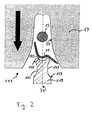
- Fig. 1 shows a device 11 for striking a line 13 to a connecting element 15 according to the prior art.
- the device comprises an upper die 17 into which a punch-shaped lower die 19 engages.
- the upper die 17 and the lower die 19 each have one Pressing surface 21 and 23, respectively, by which the shape of a crimped connection is established, which is produced by the striking of the line 13 to the connecting element 15.
- the line 13 may include multiple line strands.
- the connecting element 15 is shown by way of example as a wire claw, so that a so-called wire crimp is produced by striking the wire to the wire claw.
- the device 11 it is also possible for example to produce an insulation crimp in which insulating material is provided between the connecting element and the conductor.
- the upper die 17 is pressed against the lower die 19 by a pressing force acting in the direction of the arrow 25.
- the line 13 and the connecting element 15 are plastically deformed, and there is a permanent, no longer releasable connection between them.
- a faulty striking of the line 13 to the connecting element 15 occurs, for example, when its right half 15a, as in Fig. 1 represented, is bent incorrectly downwards. Accordingly, when the upper die 17 is pressed against the lower die 19, the right half of the connecting member 15 is outside the predetermined range between the pressing surfaces 21 and 23. As in Fig. 3a As shown, the portion 15a of the connecting member passes between the side surfaces 27 and 29 of the upper and lower dies and causes very large forces to occur due to an extremely small gap required between the side surfaces 27 and 29 for producing the crimped connection. These forces can move the upper die 17 and the lower die 19 against each other. Furthermore, the forces and the resulting torques lead to very high mechanical Tensions in the upper die 17 and the lower die 19, which can be deformed or even destroyed.
- a faulty striking of the line 13 to the connecting element 15 can except by a bent connecting element 15, as shown in FIG Fig. 1 is shown, also occur in that the upper die 17 and the lower die 19 are shifted relative to a common central axis 31 against each other. Also, the line 13 and / or the connecting element 15 with respect to the central axis 31 may be moved.
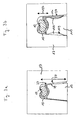
- Fig. 2 shows a device 111 according to the invention for striking a line 13 to a connecting element 15, which has a modified lower die 119, with which the problems described above are solved.
- the lower die 119 on both side surfaces 129 each have a recess 133 into which misdirected material that can escape from the conduit 13 and / or the connecting element 15 is received.
- the two recesses 133 are formed as an undercut and arranged symmetrically to the central axis 31 and the pressing surface 123 of the lower die 119 so as to accommodate misdirected material on both side surfaces 129 can.
- the lower die 119 is tapered below the pressing surface 123, and the width of the lower die 119 is greater in the region of the pressing surface 123 than in the region of the taper.
- the recesses 133 are trough-shaped and have rounded edges 135 to facilitate entry of the misguided material into the recess 133. Furthermore, there are no increased demands on the edge strength of the material from which the lower die 119 is made.
- the depth of the trough-shaped recesses 133 is significantly less than their length along the respective side surface 129.
- the volume defined by the recesses 133 between the lower die 119 and the upper die 17 is preferably selected so that sufficient misdirected material can be received in the recesses 133.
- the volume defined by the two recesses 133 may, for example, correspond to the volume of the connecting element 15.
- FIG Fig. 3a and 3b show an enlarged section of the Fig. 1 or 2, wherein the line 13 and the connecting element 15 are already pressed into the predetermined range. Material of the connecting member 15 has leaked along the side surfaces 27, 29 and 129 of the upper die 17 and the lower die 19 and 119 from the predetermined range.
- the misguided material is in Fig. 3a due to the missing recess 133 of the lower die 19 on the average further from the predetermined range than in Fig. 3b and exercises forces with a relatively large Lever arm 37 on the side surfaces 27 and 29 of the upper and lower die 17 and 19, respectively. As a result, significant torques and mechanical stresses on the upper die 17 and the lower die 19 are exercised.
- the misguided material is in Fig. 3b received in the recess 133 of the lower die 119 according to the invention.
- the dimensions of the recesses 133 may preferably be chosen such that in most cases the material picked up no longer contacts one of the side surfaces 27, 29 or 129 over the entire surface.
- the material received in the recess 133 exerts little or no force on the side surface 129 of the lower die 119 or on the side surface 27 of the upper die 17, and the resulting lever arm 137 is smaller than that in FIG Fig. 3a shown lever arm 37 significantly shortened.
- the shortened lever arm 137 reduces the mechanical stresses within the upper die 17 and the lower die 119. As a result, the likelihood of damage to the upper and / or lower dies 17 and 119, respectively, in the event of a faulty strike of the line 13 to the connecting element 15 is reduced. Further, the side and pressing surfaces 27, 129, 21 and 123 are less stressed by the lower mechanical stresses, so that the formation of grooves, in particular on the surfaces 27 and 123 is less likely. Thus, the life of the upper die 17 and the lower die 119 is lengthened by the recess 133 as a whole, so that larger numbers of crimp connections can be made without having to replace the upper and / or lower die 17 and 119 respectively.
Landscapes
- Engineering & Computer Science (AREA)
- Manufacturing & Machinery (AREA)
- Manufacturing Of Electrical Connectors (AREA)
- Pressure Welding/Diffusion-Bonding (AREA)
- Installation Of Indoor Wiring (AREA)
- Wire Processing (AREA)
- Processing Of Terminals (AREA)
- Forging (AREA)
Priority Applications (6)
| Application Number | Priority Date | Filing Date | Title |
|---|---|---|---|
| EP09003761.5A EP2230732B1 (fr) | 2009-03-16 | 2009-03-16 | Dispositif pour sertir un conducteur sur un élément de connexion |
| JP2012500100A JP5350533B2 (ja) | 2009-03-16 | 2010-02-23 | 線と接続要素の固定装置 |
| CN201080011010.5A CN102341973B (zh) | 2009-03-16 | 2010-02-23 | 将线固定于连接元件的装置 |
| KR1020117023738A KR101662555B1 (ko) | 2009-03-16 | 2010-02-23 | 라인을 연결 요소에 고정하기 위한 장치 |
| US13/203,859 US8813341B2 (en) | 2009-03-16 | 2010-02-23 | Device for attaching a line to a connecting element |
| PCT/EP2010/001149 WO2010105729A1 (fr) | 2009-03-16 | 2010-02-23 | Dispositif pour amener un conducteur en butée contre un élément de raccordement |
Applications Claiming Priority (1)
| Application Number | Priority Date | Filing Date | Title |
|---|---|---|---|
| EP09003761.5A EP2230732B1 (fr) | 2009-03-16 | 2009-03-16 | Dispositif pour sertir un conducteur sur un élément de connexion |
Publications (2)
| Publication Number | Publication Date |
|---|---|
| EP2230732A1 true EP2230732A1 (fr) | 2010-09-22 |
| EP2230732B1 EP2230732B1 (fr) | 2014-04-23 |
Family
ID=40602306
Family Applications (1)
| Application Number | Title | Priority Date | Filing Date |
|---|---|---|---|
| EP09003761.5A Not-in-force EP2230732B1 (fr) | 2009-03-16 | 2009-03-16 | Dispositif pour sertir un conducteur sur un élément de connexion |
Country Status (6)
| Country | Link |
|---|---|
| US (1) | US8813341B2 (fr) |
| EP (1) | EP2230732B1 (fr) |
| JP (1) | JP5350533B2 (fr) |
| KR (1) | KR101662555B1 (fr) |
| CN (1) | CN102341973B (fr) |
| WO (1) | WO2010105729A1 (fr) |
Families Citing this family (2)
| Publication number | Priority date | Publication date | Assignee | Title |
|---|---|---|---|---|
| DE102010022925B4 (de) * | 2010-06-07 | 2019-03-07 | Tdk Electronics Ag | Piezoelektrisches Vielschichtbauelement und Verfahren zur Ausbildung einer Außenelektrode bei einem piezoelektrischen Vielschichtbauelement |
| JP6421737B2 (ja) * | 2015-10-21 | 2018-11-14 | 株式会社オートネットワーク技術研究所 | 端子付き電線の製造方法、圧着冶具、および端子付き電線 |
Citations (4)
| Publication number | Priority date | Publication date | Assignee | Title |
|---|---|---|---|---|
| US3010183A (en) * | 1956-11-23 | 1961-11-28 | Amp Inc | Method and apparatus for forming a crimped connection |
| JPH0714658A (ja) * | 1993-06-22 | 1995-01-17 | Sumitomo Wiring Syst Ltd | 端子圧着装置及び端子圧着方法 |
| US5500999A (en) * | 1992-07-24 | 1996-03-26 | Yazaki Corporation | Terminal crimping device |
| US20080141753A1 (en) | 2006-12-14 | 2008-06-19 | Intelligent Design Group, Inc. | Method and apparatus for securing connecting ferrules |
Family Cites Families (26)
| Publication number | Priority date | Publication date | Assignee | Title |
|---|---|---|---|---|
| US2535013A (en) * | 1946-03-20 | 1950-12-19 | Aircraft Marine Prod Inc | Electrical connector |
| BE514760A (fr) * | 1951-10-11 | |||
| US2789278A (en) * | 1953-05-01 | 1957-04-16 | Controls Company | Electrical connection and method of making the same |
| NL120485C (fr) * | 1960-03-09 | |||
| JPS5133885A (ja) * | 1974-09-14 | 1976-03-23 | Minoru Mizuno | Densentodensentoosetsuzokusuru hoho oyobi sonosochi |
| GB8722564D0 (en) * | 1987-09-25 | 1987-11-04 | Amp Gmbh | Wire insertion tooling assembly |
| US5528815A (en) * | 1990-04-03 | 1996-06-25 | Webb; Edward L. T. | Clinching tool for sheet metal joining |
| US5099570A (en) * | 1991-06-27 | 1992-03-31 | Amp Incorporated | Self aligning inserter |
| US5561267A (en) * | 1993-11-30 | 1996-10-01 | Sumitomo Wiring Systems, Ltd. | Crimp terminal and process for producing the same |
| JPH08315947A (ja) * | 1995-05-12 | 1996-11-29 | Yazaki Corp | 圧接治具 |
| JP3517061B2 (ja) * | 1996-09-03 | 2004-04-05 | 矢崎総業株式会社 | 圧接端子の電線圧接方法及び圧接装置 |
| CN1208986A (zh) * | 1997-08-20 | 1999-02-24 | 博山电机厂 | 直流电机绕组与换向器的冷冲压联接方法 |
| DE19737863B4 (de) * | 1997-08-29 | 2015-07-16 | The Whitaker Corp. | Elektrischer Verbinder und Verfahren zur Herstellung eines Isolationscrimpes |
| JP3731783B2 (ja) * | 1997-09-05 | 2006-01-05 | 矢崎総業株式会社 | 端子の圧着方法および圧着装置 |
| US6035521A (en) * | 1997-11-18 | 2000-03-14 | General Motors Corporation | Multi-directional crimp plate |
| JP3394179B2 (ja) * | 1998-03-03 | 2003-04-07 | 矢崎総業株式会社 | 被覆電線の接続構造 |
| AU3925799A (en) * | 1998-03-25 | 1999-10-18 | Tox Pressotechnik Gmbh | Method, tool and punch for joining components to a plate |
| JP2001250657A (ja) * | 2000-03-03 | 2001-09-14 | Yazaki Corp | 金属端子金具の圧着片の圧着装置 |
| US6394833B1 (en) * | 2001-04-25 | 2002-05-28 | Miraco, Inc. | Flat flexible cable connector |
| JP4387612B2 (ja) * | 2001-06-13 | 2009-12-16 | 矢崎総業株式会社 | 端子圧着用歯型 |
| JP4878490B2 (ja) * | 2006-04-07 | 2012-02-15 | 矢崎総業株式会社 | 端子圧着装置及び端子圧着方法 |
| JP4846435B2 (ja) * | 2006-05-10 | 2011-12-28 | 矢崎総業株式会社 | 端子金具及び取付方法 |
| JP5196535B2 (ja) * | 2007-12-20 | 2013-05-15 | 矢崎総業株式会社 | アルミニウム電線に対する端子圧着方法 |
| JP5586354B2 (ja) * | 2010-07-15 | 2014-09-10 | 矢崎総業株式会社 | 金型及び圧着方法 |
| JP2012048833A (ja) * | 2010-08-24 | 2012-03-08 | Auto Network Gijutsu Kenkyusho:Kk | 端子圧着方法および端子圧着装置 |
| DE102010051775A1 (de) * | 2010-11-18 | 2012-05-24 | Rosenberger Hochfrequenztechnik Gmbh & Co. Kg | Form- und kraftschlüssige Crimpverbindung, insbesondere für einen Koaxialsteckverbinder und Crimpwerkzeug hierfür |
-
2009
- 2009-03-16 EP EP09003761.5A patent/EP2230732B1/fr not_active Not-in-force
-
2010
- 2010-02-23 KR KR1020117023738A patent/KR101662555B1/ko active IP Right Grant
- 2010-02-23 WO PCT/EP2010/001149 patent/WO2010105729A1/fr active Application Filing
- 2010-02-23 US US13/203,859 patent/US8813341B2/en not_active Expired - Fee Related
- 2010-02-23 CN CN201080011010.5A patent/CN102341973B/zh not_active Expired - Fee Related
- 2010-02-23 JP JP2012500100A patent/JP5350533B2/ja not_active Expired - Fee Related
Patent Citations (4)
| Publication number | Priority date | Publication date | Assignee | Title |
|---|---|---|---|---|
| US3010183A (en) * | 1956-11-23 | 1961-11-28 | Amp Inc | Method and apparatus for forming a crimped connection |
| US5500999A (en) * | 1992-07-24 | 1996-03-26 | Yazaki Corporation | Terminal crimping device |
| JPH0714658A (ja) * | 1993-06-22 | 1995-01-17 | Sumitomo Wiring Syst Ltd | 端子圧着装置及び端子圧着方法 |
| US20080141753A1 (en) | 2006-12-14 | 2008-06-19 | Intelligent Design Group, Inc. | Method and apparatus for securing connecting ferrules |
Also Published As
| Publication number | Publication date |
|---|---|
| US20110302763A1 (en) | 2011-12-15 |
| EP2230732B1 (fr) | 2014-04-23 |
| KR101662555B1 (ko) | 2016-10-05 |
| KR20110137352A (ko) | 2011-12-22 |
| US8813341B2 (en) | 2014-08-26 |
| WO2010105729A1 (fr) | 2010-09-23 |
| JP2012520549A (ja) | 2012-09-06 |
| CN102341973B (zh) | 2015-06-03 |
| CN102341973A (zh) | 2012-02-01 |
| JP5350533B2 (ja) | 2013-11-27 |
Similar Documents
| Publication | Publication Date | Title |
|---|---|---|
| DE60211880T2 (de) | Verfahren und vorrichtung zur verwendung eines verbinders für flexible flachkabel | |
| EP3235067B1 (fr) | Connecteur enfichable et méthode pour produire ce connecteur enfichable | |
| EP2144331B1 (fr) | Contact à déplacement d'isolation et dispositif de connexion | |
| DE69911911T2 (de) | Crimpanschlussklemme für flexible Leiterplatte und Crimpanordnung für Leitungsader | |
| DE102014207206A1 (de) | Elektrischer Draht-Verbindungsstruktur und elektrischer Draht Verbindungsverfahren | |
| EP3625857B1 (fr) | Moyen de décharge par traction et par pression dans un boîtier de connecteur | |
| DE102010026379A1 (de) | Crimpanschlusspassstück, Verfahren zum Bilden desselben und Draht mit Anschlusspassstück | |
| EP2606538B1 (fr) | Connecteur | |
| DE4111054C2 (fr) | ||
| DE102019200121A1 (de) | Crimp zum Verbinden von Drähten | |
| EP1972033A2 (fr) | Cellule de contact destinee a recevoir une extremite de cable par le procede a borne guillotine et procede de fabrication | |
| EP2230732B1 (fr) | Dispositif pour sertir un conducteur sur un élément de connexion | |
| EP3717391A1 (fr) | Élément de raccordement destiné à la mise en contact électrique de tirants dans une courroie apte à porter une charge destinée à une installation d'ascenseur, ainsi que procédé de montage d'un élément de raccordement sur la courroie | |
| EP1493053A1 (fr) | Connecteur de fibres optiques comportant des saillies de sertissage | |
| DE102012216895B3 (de) | Verdrillen von Leitungen mit Vorsteckelement | |
| EP3419121B1 (fr) | Procédé de fabrication d'une liaison électrique et système de soudure par ultrasons | |
| DE102019104400A1 (de) | Einpresskontakt und Verfahren zum Herstellen des Einpresskontakts | |
| EP3857584B1 (fr) | Fiche pour un profilé de sécurité et une baguette de commutation | |
| DE102012215652A1 (de) | Drucksensor mit Verbinder mit einer flexiblen Pin-Anordnung | |
| EP1063724A1 (fr) | Connexion de sertissage | |
| DE102022117760B3 (de) | Elektrisches Kontaktelement | |
| DE102016223475A1 (de) | Verbindungsanordnung und Verfahren zur Herstellung einer Verbindungsanordnung für Litzenleiter in einer Führung | |
| DE102008031686A1 (de) | Verbesserte Halteschutzbuchse eines Steckverbinders | |
| EP2006963A1 (fr) | Procédé de fixation d'une cosse et dispositif de boucle de câble | |
| DE102021127516A1 (de) | Elektroleitung mit Anschluss und Anschluss-Crimpvorrichtung |
Legal Events
| Date | Code | Title | Description |
|---|---|---|---|
| PUAI | Public reference made under article 153(3) epc to a published international application that has entered the european phase |
Free format text: ORIGINAL CODE: 0009012 |
|
| 17P | Request for examination filed |
Effective date: 20091202 |
|
| AK | Designated contracting states |
Kind code of ref document: A1 Designated state(s): AT BE BG CH CY CZ DE DK EE ES FI FR GB GR HR HU IE IS IT LI LT LU LV MC MK MT NL NO PL PT RO SE SI SK TR |
|
| AX | Request for extension of the european patent |
Extension state: AL BA RS |
|
| AKX | Designation fees paid |
Designated state(s): AT BE BG CH CY CZ DE DK EE ES FI FR GB GR HR HU IE IS IT LI LT LU LV MC MK MT NL NO PL PT RO SE SI SK TR |
|
| RIC1 | Information provided on ipc code assigned before grant |
Ipc: H01R 4/18 20060101ALI20120209BHEP Ipc: H01R 43/058 20060101AFI20120209BHEP |
|
| 17Q | First examination report despatched |
Effective date: 20120410 |
|
| GRAP | Despatch of communication of intention to grant a patent |
Free format text: ORIGINAL CODE: EPIDOSNIGR1 |
|
| INTG | Intention to grant announced |
Effective date: 20131023 |
|
| GRAS | Grant fee paid |
Free format text: ORIGINAL CODE: EPIDOSNIGR3 |
|
| GRAA | (expected) grant |
Free format text: ORIGINAL CODE: 0009210 |
|
| AK | Designated contracting states |
Kind code of ref document: B1 Designated state(s): AT BE BG CH CY CZ DE DK EE ES FI FR GB GR HR HU IE IS IT LI LT LU LV MC MK MT NL NO PL PT RO SE SI SK TR |
|
| REG | Reference to a national code |
Ref country code: GB Ref legal event code: FG4D Free format text: NOT ENGLISH |
|
| REG | Reference to a national code |
Ref country code: CH Ref legal event code: EP |
|
| REG | Reference to a national code |
Ref country code: AT Ref legal event code: REF Ref document number: 664325 Country of ref document: AT Kind code of ref document: T Effective date: 20140515 |
|
| REG | Reference to a national code |
Ref country code: IE Ref legal event code: FG4D Free format text: LANGUAGE OF EP DOCUMENT: GERMAN |
|
| REG | Reference to a national code |
Ref country code: DE Ref legal event code: R096 Ref document number: 502009009222 Country of ref document: DE Effective date: 20140612 |
|
| REG | Reference to a national code |
Ref country code: NL Ref legal event code: VDEP Effective date: 20140423 |
|
| REG | Reference to a national code |
Ref country code: LT Ref legal event code: MG4D |
|
| PG25 | Lapsed in a contracting state [announced via postgrant information from national office to epo] |
Ref country code: NO Free format text: LAPSE BECAUSE OF FAILURE TO SUBMIT A TRANSLATION OF THE DESCRIPTION OR TO PAY THE FEE WITHIN THE PRESCRIBED TIME-LIMIT Effective date: 20140723 Ref country code: LT Free format text: LAPSE BECAUSE OF FAILURE TO SUBMIT A TRANSLATION OF THE DESCRIPTION OR TO PAY THE FEE WITHIN THE PRESCRIBED TIME-LIMIT Effective date: 20140423 Ref country code: GR Free format text: LAPSE BECAUSE OF FAILURE TO SUBMIT A TRANSLATION OF THE DESCRIPTION OR TO PAY THE FEE WITHIN THE PRESCRIBED TIME-LIMIT Effective date: 20140724 Ref country code: IS Free format text: LAPSE BECAUSE OF FAILURE TO SUBMIT A TRANSLATION OF THE DESCRIPTION OR TO PAY THE FEE WITHIN THE PRESCRIBED TIME-LIMIT Effective date: 20140823 Ref country code: FI Free format text: LAPSE BECAUSE OF FAILURE TO SUBMIT A TRANSLATION OF THE DESCRIPTION OR TO PAY THE FEE WITHIN THE PRESCRIBED TIME-LIMIT Effective date: 20140423 Ref country code: BG Free format text: LAPSE BECAUSE OF FAILURE TO SUBMIT A TRANSLATION OF THE DESCRIPTION OR TO PAY THE FEE WITHIN THE PRESCRIBED TIME-LIMIT Effective date: 20140723 Ref country code: NL Free format text: LAPSE BECAUSE OF FAILURE TO SUBMIT A TRANSLATION OF THE DESCRIPTION OR TO PAY THE FEE WITHIN THE PRESCRIBED TIME-LIMIT Effective date: 20140423 Ref country code: CY Free format text: LAPSE BECAUSE OF FAILURE TO SUBMIT A TRANSLATION OF THE DESCRIPTION OR TO PAY THE FEE WITHIN THE PRESCRIBED TIME-LIMIT Effective date: 20140423 |
|
| PG25 | Lapsed in a contracting state [announced via postgrant information from national office to epo] |
Ref country code: ES Free format text: LAPSE BECAUSE OF FAILURE TO SUBMIT A TRANSLATION OF THE DESCRIPTION OR TO PAY THE FEE WITHIN THE PRESCRIBED TIME-LIMIT Effective date: 20140423 Ref country code: HR Free format text: LAPSE BECAUSE OF FAILURE TO SUBMIT A TRANSLATION OF THE DESCRIPTION OR TO PAY THE FEE WITHIN THE PRESCRIBED TIME-LIMIT Effective date: 20140423 Ref country code: PL Free format text: LAPSE BECAUSE OF FAILURE TO SUBMIT A TRANSLATION OF THE DESCRIPTION OR TO PAY THE FEE WITHIN THE PRESCRIBED TIME-LIMIT Effective date: 20140423 Ref country code: LV Free format text: LAPSE BECAUSE OF FAILURE TO SUBMIT A TRANSLATION OF THE DESCRIPTION OR TO PAY THE FEE WITHIN THE PRESCRIBED TIME-LIMIT Effective date: 20140423 Ref country code: SE Free format text: LAPSE BECAUSE OF FAILURE TO SUBMIT A TRANSLATION OF THE DESCRIPTION OR TO PAY THE FEE WITHIN THE PRESCRIBED TIME-LIMIT Effective date: 20140423 |
|
| PG25 | Lapsed in a contracting state [announced via postgrant information from national office to epo] |
Ref country code: PT Free format text: LAPSE BECAUSE OF FAILURE TO SUBMIT A TRANSLATION OF THE DESCRIPTION OR TO PAY THE FEE WITHIN THE PRESCRIBED TIME-LIMIT Effective date: 20140825 |
|
| REG | Reference to a national code |
Ref country code: DE Ref legal event code: R097 Ref document number: 502009009222 Country of ref document: DE |
|
| PG25 | Lapsed in a contracting state [announced via postgrant information from national office to epo] |
Ref country code: SK Free format text: LAPSE BECAUSE OF FAILURE TO SUBMIT A TRANSLATION OF THE DESCRIPTION OR TO PAY THE FEE WITHIN THE PRESCRIBED TIME-LIMIT Effective date: 20140423 Ref country code: DK Free format text: LAPSE BECAUSE OF FAILURE TO SUBMIT A TRANSLATION OF THE DESCRIPTION OR TO PAY THE FEE WITHIN THE PRESCRIBED TIME-LIMIT Effective date: 20140423 Ref country code: RO Free format text: LAPSE BECAUSE OF FAILURE TO SUBMIT A TRANSLATION OF THE DESCRIPTION OR TO PAY THE FEE WITHIN THE PRESCRIBED TIME-LIMIT Effective date: 20140423 Ref country code: EE Free format text: LAPSE BECAUSE OF FAILURE TO SUBMIT A TRANSLATION OF THE DESCRIPTION OR TO PAY THE FEE WITHIN THE PRESCRIBED TIME-LIMIT Effective date: 20140423 Ref country code: CZ Free format text: LAPSE BECAUSE OF FAILURE TO SUBMIT A TRANSLATION OF THE DESCRIPTION OR TO PAY THE FEE WITHIN THE PRESCRIBED TIME-LIMIT Effective date: 20140423 |
|
| PLBE | No opposition filed within time limit |
Free format text: ORIGINAL CODE: 0009261 |
|
| STAA | Information on the status of an ep patent application or granted ep patent |
Free format text: STATUS: NO OPPOSITION FILED WITHIN TIME LIMIT |
|
| 26N | No opposition filed |
Effective date: 20150126 |
|
| REG | Reference to a national code |
Ref country code: DE Ref legal event code: R097 Ref document number: 502009009222 Country of ref document: DE Effective date: 20150126 |
|
| PG25 | Lapsed in a contracting state [announced via postgrant information from national office to epo] |
Ref country code: SI Free format text: LAPSE BECAUSE OF FAILURE TO SUBMIT A TRANSLATION OF THE DESCRIPTION OR TO PAY THE FEE WITHIN THE PRESCRIBED TIME-LIMIT Effective date: 20140423 |
|
| PG25 | Lapsed in a contracting state [announced via postgrant information from national office to epo] |
Ref country code: LU Free format text: LAPSE BECAUSE OF FAILURE TO SUBMIT A TRANSLATION OF THE DESCRIPTION OR TO PAY THE FEE WITHIN THE PRESCRIBED TIME-LIMIT Effective date: 20150316 Ref country code: MC Free format text: LAPSE BECAUSE OF FAILURE TO SUBMIT A TRANSLATION OF THE DESCRIPTION OR TO PAY THE FEE WITHIN THE PRESCRIBED TIME-LIMIT Effective date: 20140423 |
|
| REG | Reference to a national code |
Ref country code: CH Ref legal event code: PL |
|
| REG | Reference to a national code |
Ref country code: IE Ref legal event code: MM4A |
|
| PG25 | Lapsed in a contracting state [announced via postgrant information from national office to epo] |
Ref country code: LI Free format text: LAPSE BECAUSE OF NON-PAYMENT OF DUE FEES Effective date: 20150331 Ref country code: CH Free format text: LAPSE BECAUSE OF NON-PAYMENT OF DUE FEES Effective date: 20150331 Ref country code: IE Free format text: LAPSE BECAUSE OF NON-PAYMENT OF DUE FEES Effective date: 20150316 |
|
| REG | Reference to a national code |
Ref country code: FR Ref legal event code: PLFP Year of fee payment: 8 |
|
| REG | Reference to a national code |
Ref country code: AT Ref legal event code: MM01 Ref document number: 664325 Country of ref document: AT Kind code of ref document: T Effective date: 20150316 |
|
| PG25 | Lapsed in a contracting state [announced via postgrant information from national office to epo] |
Ref country code: AT Free format text: LAPSE BECAUSE OF NON-PAYMENT OF DUE FEES Effective date: 20150316 |
|
| PG25 | Lapsed in a contracting state [announced via postgrant information from national office to epo] |
Ref country code: MT Free format text: LAPSE BECAUSE OF FAILURE TO SUBMIT A TRANSLATION OF THE DESCRIPTION OR TO PAY THE FEE WITHIN THE PRESCRIBED TIME-LIMIT Effective date: 20140423 |
|
| REG | Reference to a national code |
Ref country code: FR Ref legal event code: PLFP Year of fee payment: 9 |
|
| PG25 | Lapsed in a contracting state [announced via postgrant information from national office to epo] |
Ref country code: HU Free format text: LAPSE BECAUSE OF FAILURE TO SUBMIT A TRANSLATION OF THE DESCRIPTION OR TO PAY THE FEE WITHIN THE PRESCRIBED TIME-LIMIT; INVALID AB INITIO Effective date: 20090316 |
|
| PG25 | Lapsed in a contracting state [announced via postgrant information from national office to epo] |
Ref country code: BE Free format text: LAPSE BECAUSE OF NON-PAYMENT OF DUE FEES Effective date: 20150331 |
|
| PG25 | Lapsed in a contracting state [announced via postgrant information from national office to epo] |
Ref country code: TR Free format text: LAPSE BECAUSE OF FAILURE TO SUBMIT A TRANSLATION OF THE DESCRIPTION OR TO PAY THE FEE WITHIN THE PRESCRIBED TIME-LIMIT Effective date: 20140423 |
|
| REG | Reference to a national code |
Ref country code: FR Ref legal event code: PLFP Year of fee payment: 10 |
|
| PGFP | Annual fee paid to national office [announced via postgrant information from national office to epo] |
Ref country code: GB Payment date: 20180327 Year of fee payment: 10 |
|
| PGFP | Annual fee paid to national office [announced via postgrant information from national office to epo] |
Ref country code: IT Payment date: 20180322 Year of fee payment: 10 Ref country code: FR Payment date: 20180326 Year of fee payment: 10 |
|
| PG25 | Lapsed in a contracting state [announced via postgrant information from national office to epo] |
Ref country code: MK Free format text: LAPSE BECAUSE OF FAILURE TO SUBMIT A TRANSLATION OF THE DESCRIPTION OR TO PAY THE FEE WITHIN THE PRESCRIBED TIME-LIMIT Effective date: 20140423 |
|
| PGFP | Annual fee paid to national office [announced via postgrant information from national office to epo] |
Ref country code: DE Payment date: 20180328 Year of fee payment: 10 |
|
| REG | Reference to a national code |
Ref country code: DE Ref legal event code: R119 Ref document number: 502009009222 Country of ref document: DE |
|
| GBPC | Gb: european patent ceased through non-payment of renewal fee |
Effective date: 20190316 |
|
| PG25 | Lapsed in a contracting state [announced via postgrant information from national office to epo] |
Ref country code: DE Free format text: LAPSE BECAUSE OF NON-PAYMENT OF DUE FEES Effective date: 20191001 Ref country code: GB Free format text: LAPSE BECAUSE OF NON-PAYMENT OF DUE FEES Effective date: 20190316 |
|
| PG25 | Lapsed in a contracting state [announced via postgrant information from national office to epo] |
Ref country code: IT Free format text: LAPSE BECAUSE OF NON-PAYMENT OF DUE FEES Effective date: 20190316 Ref country code: FR Free format text: LAPSE BECAUSE OF NON-PAYMENT OF DUE FEES Effective date: 20190331 |