EP2230732A1 - Device for attaching a cable to a connection element - Google Patents
Device for attaching a cable to a connection element Download PDFInfo
- Publication number
- EP2230732A1 EP2230732A1 EP09003761A EP09003761A EP2230732A1 EP 2230732 A1 EP2230732 A1 EP 2230732A1 EP 09003761 A EP09003761 A EP 09003761A EP 09003761 A EP09003761 A EP 09003761A EP 2230732 A1 EP2230732 A1 EP 2230732A1
- Authority
- EP
- European Patent Office
- Prior art keywords
- recess
- lower die
- connecting element
- die
- upper die
- Prior art date
- Legal status (The legal status is an assumption and is not a legal conclusion. Google has not performed a legal analysis and makes no representation as to the accuracy of the status listed.)
- Granted
Links
Images

Classifications
-
- H—ELECTRICITY
- H01—ELECTRIC ELEMENTS
- H01R—ELECTRICALLY-CONDUCTIVE CONNECTIONS; STRUCTURAL ASSOCIATIONS OF A PLURALITY OF MUTUALLY-INSULATED ELECTRICAL CONNECTING ELEMENTS; COUPLING DEVICES; CURRENT COLLECTORS
- H01R43/00—Apparatus or processes specially adapted for manufacturing, assembling, maintaining, or repairing of line connectors or current collectors or for joining electric conductors
- H01R43/04—Apparatus or processes specially adapted for manufacturing, assembling, maintaining, or repairing of line connectors or current collectors or for joining electric conductors for forming connections by deformation, e.g. crimping tool
- H01R43/058—Crimping mandrels
-
- H—ELECTRICITY
- H01—ELECTRIC ELEMENTS
- H01R—ELECTRICALLY-CONDUCTIVE CONNECTIONS; STRUCTURAL ASSOCIATIONS OF A PLURALITY OF MUTUALLY-INSULATED ELECTRICAL CONNECTING ELEMENTS; COUPLING DEVICES; CURRENT COLLECTORS
- H01R4/00—Electrically-conductive connections between two or more conductive members in direct contact, i.e. touching one another; Means for effecting or maintaining such contact; Electrically-conductive connections having two or more spaced connecting locations for conductors and using contact members penetrating insulation
- H01R4/10—Electrically-conductive connections between two or more conductive members in direct contact, i.e. touching one another; Means for effecting or maintaining such contact; Electrically-conductive connections having two or more spaced connecting locations for conductors and using contact members penetrating insulation effected solely by twisting, wrapping, bending, crimping, or other permanent deformation
- H01R4/18—Electrically-conductive connections between two or more conductive members in direct contact, i.e. touching one another; Means for effecting or maintaining such contact; Electrically-conductive connections having two or more spaced connecting locations for conductors and using contact members penetrating insulation effected solely by twisting, wrapping, bending, crimping, or other permanent deformation by crimping
- H01R4/183—Electrically-conductive connections between two or more conductive members in direct contact, i.e. touching one another; Means for effecting or maintaining such contact; Electrically-conductive connections having two or more spaced connecting locations for conductors and using contact members penetrating insulation effected solely by twisting, wrapping, bending, crimping, or other permanent deformation by crimping for cylindrical elongated bodies, e.g. cables having circular cross-section
-
- Y—GENERAL TAGGING OF NEW TECHNOLOGICAL DEVELOPMENTS; GENERAL TAGGING OF CROSS-SECTIONAL TECHNOLOGIES SPANNING OVER SEVERAL SECTIONS OF THE IPC; TECHNICAL SUBJECTS COVERED BY FORMER USPC CROSS-REFERENCE ART COLLECTIONS [XRACs] AND DIGESTS
- Y10—TECHNICAL SUBJECTS COVERED BY FORMER USPC
- Y10T—TECHNICAL SUBJECTS COVERED BY FORMER US CLASSIFICATION
- Y10T29/00—Metal working
- Y10T29/49—Method of mechanical manufacture
- Y10T29/49002—Electrical device making
- Y10T29/49117—Conductor or circuit manufacturing
- Y10T29/49124—On flat or curved insulated base, e.g., printed circuit, etc.
- Y10T29/4913—Assembling to base an electrical component, e.g., capacitor, etc.
- Y10T29/49139—Assembling to base an electrical component, e.g., capacitor, etc. by inserting component lead or terminal into base aperture
- Y10T29/4914—Assembling to base an electrical component, e.g., capacitor, etc. by inserting component lead or terminal into base aperture with deforming of lead or terminal
-
- Y—GENERAL TAGGING OF NEW TECHNOLOGICAL DEVELOPMENTS; GENERAL TAGGING OF CROSS-SECTIONAL TECHNOLOGIES SPANNING OVER SEVERAL SECTIONS OF THE IPC; TECHNICAL SUBJECTS COVERED BY FORMER USPC CROSS-REFERENCE ART COLLECTIONS [XRACs] AND DIGESTS
- Y10—TECHNICAL SUBJECTS COVERED BY FORMER USPC
- Y10T—TECHNICAL SUBJECTS COVERED BY FORMER US CLASSIFICATION
- Y10T29/00—Metal working
- Y10T29/49—Method of mechanical manufacture
- Y10T29/49002—Electrical device making
- Y10T29/49117—Conductor or circuit manufacturing
- Y10T29/49174—Assembling terminal to elongated conductor
- Y10T29/49181—Assembling terminal to elongated conductor by deforming
- Y10T29/49183—Assembling terminal to elongated conductor by deforming of ferrule about conductor and terminal
-
- Y—GENERAL TAGGING OF NEW TECHNOLOGICAL DEVELOPMENTS; GENERAL TAGGING OF CROSS-SECTIONAL TECHNOLOGIES SPANNING OVER SEVERAL SECTIONS OF THE IPC; TECHNICAL SUBJECTS COVERED BY FORMER USPC CROSS-REFERENCE ART COLLECTIONS [XRACs] AND DIGESTS
- Y10—TECHNICAL SUBJECTS COVERED BY FORMER USPC
- Y10T—TECHNICAL SUBJECTS COVERED BY FORMER US CLASSIFICATION
- Y10T29/00—Metal working
- Y10T29/49—Method of mechanical manufacture
- Y10T29/49826—Assembling or joining
- Y10T29/49908—Joining by deforming
- Y10T29/49925—Inward deformation of aperture or hollow body wall
-
- Y—GENERAL TAGGING OF NEW TECHNOLOGICAL DEVELOPMENTS; GENERAL TAGGING OF CROSS-SECTIONAL TECHNOLOGIES SPANNING OVER SEVERAL SECTIONS OF THE IPC; TECHNICAL SUBJECTS COVERED BY FORMER USPC CROSS-REFERENCE ART COLLECTIONS [XRACs] AND DIGESTS
- Y10—TECHNICAL SUBJECTS COVERED BY FORMER USPC
- Y10T—TECHNICAL SUBJECTS COVERED BY FORMER US CLASSIFICATION
- Y10T29/00—Metal working
- Y10T29/53—Means to assemble or disassemble
- Y10T29/5313—Means to assemble electrical device
- Y10T29/532—Conductor
- Y10T29/53209—Terminal or connector
- Y10T29/53213—Assembled to wire-type conductor
- Y10T29/53222—Means comprising hand-manipulatable implement
- Y10T29/53226—Fastening by deformation
-
- Y—GENERAL TAGGING OF NEW TECHNOLOGICAL DEVELOPMENTS; GENERAL TAGGING OF CROSS-SECTIONAL TECHNOLOGIES SPANNING OVER SEVERAL SECTIONS OF THE IPC; TECHNICAL SUBJECTS COVERED BY FORMER USPC CROSS-REFERENCE ART COLLECTIONS [XRACs] AND DIGESTS
- Y10—TECHNICAL SUBJECTS COVERED BY FORMER USPC
- Y10T—TECHNICAL SUBJECTS COVERED BY FORMER US CLASSIFICATION
- Y10T29/00—Metal working
- Y10T29/53—Means to assemble or disassemble
- Y10T29/5313—Means to assemble electrical device
- Y10T29/532—Conductor
- Y10T29/53209—Terminal or connector
- Y10T29/53213—Assembled to wire-type conductor
- Y10T29/53235—Means to fasten by deformation
-
- Y—GENERAL TAGGING OF NEW TECHNOLOGICAL DEVELOPMENTS; GENERAL TAGGING OF CROSS-SECTIONAL TECHNOLOGIES SPANNING OVER SEVERAL SECTIONS OF THE IPC; TECHNICAL SUBJECTS COVERED BY FORMER USPC CROSS-REFERENCE ART COLLECTIONS [XRACs] AND DIGESTS
- Y10—TECHNICAL SUBJECTS COVERED BY FORMER USPC
- Y10T—TECHNICAL SUBJECTS COVERED BY FORMER US CLASSIFICATION
- Y10T29/00—Metal working
- Y10T29/53—Means to assemble or disassemble
- Y10T29/5313—Means to assemble electrical device
- Y10T29/5327—Means to fasten by deforming
Abstract
Description
Die vorliegende Erfindung betrifft eine Vorrichtung und ein Verfahren zum Anschlagen einer Leitung an ein Verbindungselement. Die Vorrichtung umfasst ein Obergesenk und ein Untergesenk, die jeweils eine Pressfläche aufweisen, um die Leitung und das Verbindungselement in einem vorbestimmten Bereich zwischen dem Untergesenk und dem Obergesenk zu pressen.The present invention relates to an apparatus and method for striking a conduit to a connector. The apparatus includes an upper die and a lower die, each having a pressing surface to press the conduit and the connecting member in a predetermined area between the lower die and the upper die.
Derartige Vorrichtungen und Verfahren werden beispielsweise in der elektrischen Verbindungstechnik verwendet, um eine nicht mehr lösbare Verbindung zwischen einer Leitung und einem Verbindungselement herzustellen. Die Leitung und das Verbindungselement werden dabei durch eine plastische Verformung miteinander verbunden, die durch eine Presskraft hervorgerufen wird. Durch eine derartige Verbindung können die Leitung und das Verbindungselement ferner elektrisch kontaktiert werden, wobei das Verbindungselement als ein beliebiges Kontaktelement, z.B. als ein Stecker, ausgebildet sein kann.Such devices and methods are used for example in electrical connection technology to produce a no longer detachable connection between a line and a connecting element. The line and the connecting element are connected to each other by a plastic deformation, which is caused by a pressing force. By such a connection, the lead and the connecting element can be further electrically contacted, wherein the connecting element as any contact element, e.g. as a plug can be formed.
Die Verbindung zwischen dem Leiter und dem Verbindungselement kann beispielsweise durch Crimpen oder Splicen hergestellt werden. Beim Crimpen werden üblicherweise vorgeformte Verbindungselemente verwendet, deren Abmessungen, insbesondere deren Länge, mit dem Querschnitt der Leitung abgestimmt sind. Ferner weisen Crimpwerkzeuge vorbestimmte Profile auf, um eine vorgebbare Verformung der Leitung und des Verbindungselements herbeizuführen und die Crimpverbindung dadurch in einer gewünschten Form auszubilden. Beim Splicen wird anstelle eines vorgeformten Verbindungselements ein Endlosband verwendet.The connection between the conductor and the connecting element can be produced for example by crimping or splicing. When crimping usually preformed fasteners are used whose dimensions, in particular their length, are matched to the cross section of the line. Furthermore, crimping tools have predetermined profiles in order to bring about a predeterminable deformation of the line and the connecting element and thereby the crimped connection in one form the desired shape. When splicing an endless belt is used instead of a preformed connecting element.
Eine Crimpverbindung kann im einfachsten Fall mittels einer Crimpzange erzeugt werden. Wenn jedoch eine große Anzahl Crimpverbindungen in kurzer Zeit erzeugt werden soll, beispielsweise bei der Herstellung spezieller Kabel mit besonderen Kontaktelementen, werden automatisierte Vorrichtungen verwendet. Eine derartige Vorrichtung ist in
Da die äußere Form der Crimpverbindung durch die Form der Pressflächen des Ober- und Untergesenks definiert werden soll, ist zwischen den Flanken bzw. Seitenflächen des Ober- und Untergesenks ein extrem kleines Spaltmaß notwendig. In der Praxis können bei der Herstellung der Crimpverbindung dennoch verschiedene Arten von Fehlern auftreten. Beispielsweise kann das Verbindungselement bereits deformiert sein, bevor es die Vorrichtung erreicht. Die Leitung und das Verbindungselement können gegenüber einer Mittelachse des Ober- und Untergesenks verschoben oder verdreht sein. Ferner können das Ober- und das Untergesenk relativ zueinander verschoben sein.Since the outer shape of the crimped connection is to be defined by the shape of the pressing surfaces of the upper and lower dies, an extremely small gap size is required between the flanks or side surfaces of the upper and lower dies. In practice, however, various types of defects may occur in the manufacture of the crimped connection. For example, the connecting element may already be deformed before it reaches the device. The conduit and the connecting element may be displaced or twisted with respect to a central axis of the upper and lower dies. Furthermore, the upper and lower dies can be displaced relative to each other.
Dadurch kann eine so genannte Fehlcrimpung auftreten, bei der Material der Leitung und/oder des Verbindungselements aus dem vorbestimmten Bereich zwischen den Pressflächen austritt und zwischen die Flanken bzw. Seitenflächen des Ober- und Untergesenks gelangt. Da ein auf diese Weise fehlgeleitetes Material der Leitung und/oder des Verbindungselements meistens unsymmetrisch bezüglich der Mittelachse des Ober- und Untergesenks verteilt ist, wirken bei Fehlcrimpungen aufgrund der großen Presskraft große Drehmomente auf die Seitenflächen des Ober- und Untergesenks. Dadurch können das Ober- und Untergesenk gegeneinander verschoben werden, und es treten hohe mechanische Spannungen auf. Durch diese Spannungen können das Ober- und Untergesenk deformiert oder sogar zerstört werden. Die beiden Seitenflächen des Obergesenks können beispielsweise durch die Spannungen auseinander gebogen werden, bis ein Abschnitt des Obergesenks abbricht. Ferner werden die Seiten- und Pressflächen des Ober- und Untergesenks durch die mechanischen Spannungen stark beansprucht, so dass es zur Ausbildung von Riefen in den Pressflächen kommen kann. Somit verringern Fehlcrimpungen die Lebensdauer des Ober- und Untergesenks.As a result, so-called Fehlcrimpung occur in the material of the line and / or the connecting element from the predetermined area between the pressing surfaces emerges and passes between the flanks or side surfaces of the upper and lower die. As a misdirected in this way material of the line and / or the connecting element is distributed mostly asymmetrically with respect to the central axis of the upper and lower die, acting in Fehlcrimpungen due to the large pressing force large torques on the side surfaces of the upper and lower die. As a result, the upper and lower dies can be shifted against each other, and high mechanical stresses occur. These tensions can deform or even destroy the upper and lower dies. For example, the two side surfaces of the upper die may be bent apart by the tensions until a portion of the upper die breaks off. Furthermore, the side and pressing surfaces of the upper and lower die are heavily stressed by the mechanical stresses, so that it can lead to the formation of grooves in the pressing surfaces. Thus, false crimps reduce the life of the upper and lower dies.
Es ist daher die Aufgabe der Erfindung, eine Vorrichtung und ein Verfahren der vorstehend beschriebenen Art zum Anschlagen einer Leitung an ein Verbindungselement zu schaffen, durch welche die Wahrscheinlichkeit einer Beschädigung eines Ober- und eines Untergesenks verringert wird, wenn ein fehlerhaftes Anschlagen auftritt.It is therefore the object of the invention to provide a device and a method of the type described above for striking a line to a connecting element, by which the likelihood of damage to a top and a bottom die is reduced when a faulty striking occurs.
Diese Aufgabe wird gelöst durch eine Vorrichtung mit den Merkmalen des Anspruchs 1 und insbesondere dadurch, dass zwischen dem Obergesenk und dem Untergesenk zumindest eine Aussparung außerhalb der Pressflächen vorgesehen ist, die ausgebildet ist, um einen Teil der Leitung und/oder einen Abschnitt des Verbindungselements aufzunehmen. Fehlgeleitetes Material der Leitung und/oder des Verbindungselements, das aufgrund eines fehlerhaften Anschlagens den Bereich zwischen den Pressflächen des Ober- und Untergesenks verlässt, wird in der zumindest einen Aussparung aufgenommen und somit daran gehindert, sich noch weiter von dem Bereich zwischen den Pressflächen zu entfernen.This object is achieved by a device having the features of claim 1 and in particular by the fact that between the upper die and the lower die at least one recess is provided outside the pressing surfaces, which is adapted to receive a part of the conduit and / or a portion of the connecting element , Misguided material of the conduit and / or the connecting element, which leaves the area between the pressing surfaces of the upper and lower mold due to a faulty stop, is received in the at least one recess and thus prevented from moving farther away from the area between the pressing surfaces ,
Da sich das fehlgeleitete Material aufgrund der Aussparung insgesamt näher an den Pressflächen befindet, d.h. der Abstand zwischen den Volumenelementen des fehlgeleiteten Materials und den Pressflächen durch das Vorhandensein der Aussparung in Summe verkürzt ist, ist der Hebelarm unerwünschter Drehmomente, die auf die Seitenflächen des Ober- und Untergesenks wirken, durch das Aufnehmen des Materials in der Aussparung verkürzt. Folglich werden die unerwünschten Drehmomente und die aus diesen resultierenden Druck- und Zugspannungen auf das Ober- und Untergesenk verringert. Die Belastungsgrenzen, bei denen eine Deformation oder eine Beschädigung des Ober- und Untergesenks auftreten kann, sind durch die verringerten Drehmomente somit erheblich höher, was zu einer größeren Lebensdauer des Ober- und Untergesenks führt.Because the misguided material is closer to the pressing surfaces due to the recess altogether, i. the distance between the volume elements of the misguided material and the pressing surfaces is shortened by the presence of the recess in total, the lever arm of undesired torques acting on the side surfaces of the upper and lower dies is shortened by the reception of the material in the recess. Consequently, the undesirable torques and the resulting compressive and tensile stresses on the upper and lower dies are reduced. The load limits at which a deformation or damage of the upper and lower mold can occur are thus considerably higher due to the reduced torques, which leads to a longer service life of the upper and lower dies.
Die Aussparung zwischen dem Ober- und dem Untergesenk bewirkt ferner, dass sowohl die Seiten- als auch die Pressflächen des Ober- und Untergesenks aufgrund der geringeren Druck- und Zugspannungen weniger stark beansprucht werden, wenn ein fehlerhaftes Anschlagen auftritt. Beispielsweise wird die Ausbildung von Riefen auf den Pressflächen verringert, so dass auch dadurch die Lebensdauer des Ober- und Untergesenks verlängert wird. Folglich ist es möglich, eine größere Stückzahl von Anschlägen bzw. Crimpverbindungen mit demselben Ober- bzw. Untergesenk herzustellen.The recess between the upper and the lower die also causes both the side and the pressing surfaces of the upper and lower die are less stressed due to the lower compressive and tensile stresses when a faulty striking occurs. For example, the formation of grooves on the pressing surfaces is reduced, so that thereby the life of the upper and lower die is extended. Consequently, it is possible to produce a larger number of stops or crimps with the same upper or lower die.
Vorteilhafte Ausbildungen der Erfindung sind den Unteransprüchen, der Beschreibung und den Zeichnungen zu entnehmen.Advantageous embodiments of the invention are described in the dependent claims, the description and the drawings.
Vorteilhafterweise ist der Abstand zwischen einer der Grenzflächen und zumindest einer Kante der Aussparung geringer als die Länge, Breite und Tiefe der Aussparung. Mit anderen Worten befindet sich die Aussparung in unmittelbarer Nähe einer der Pressflächen, um fehlgeleitetes Material der Leitung und/ oder des Verbindungselements unmittelbar nach dem Verlassen des vorbestimmten Bereichs zwischen den Pressflächen aufzunehmen. Dadurch wird der Flächenabschnitt auf den Seitenflächen des Ober- bzw. Untergesenks verkleinert, auf den fehlgeleitetes Material eine Kraft ausüben kann, bevor es von der Aussparung aufgenommen wird. Ferner wird das Drehmoment, das auf die Seitenflächen des Ober- und Untergesenks ausgeübt wird, durch die Anordnung der Aussparung in der Nähe der Pressflächen minimiert, da die Länge des Hebelarms minimiert wird, der durch das fehlgeleitete Material erzeugt werden kann.Advantageously, the distance between one of the boundary surfaces and at least one edge of the recess is less than the length, width and Depth of the recess. In other words, the recess is in the immediate vicinity of one of the pressing surfaces to receive misdirected material of the conduit and / or the connecting element immediately after leaving the predetermined region between the pressing surfaces. As a result, the surface portion on the side surfaces of the upper and lower dies is reduced to the misguided material can exert a force before it is absorbed by the recess. Further, the torque exerted on the side surfaces of the upper and lower dies is minimized by the arrangement of the recess near the pressing surfaces, since the length of the lever arm that can be generated by the misdirected material is minimized.
Die Aussparung ist vorteilhafterweise als Hinterschnitt bzw. muldenförmig ausgebildet, damit die Kräfte, die das fehlgeleitete Material im Bereich der Aussparung auf das Ober- oder Untergesenk ausübt, eher tangential ausgerichtet sind, d.h. entgegengesetzt zur Richtung der eigentlichen Presskraft, und nicht rechtwinklig zu der Seitenfläche des Ober- bzw. Untergesenks. Dadurch wird das auf die Seitenflächen des Ober- bzw. Untergesenks ausgeübte Drehmoment zusätzlich verringert. Es ist ferner von Vorteil, wenn die Aussparung abgerundete Kanten aufweist, damit die Anforderungen an die Kantenfestigkeit des Materials geringer sind, aus dem das Ober- und das Untergesenk gefertigt sind. Dadurch lassen sich das Ober- bzw. das Untergesenk kostengünstiger herstellen.The recess is advantageously formed as an undercut or trough-shaped so that the forces exerted by the misdirected material in the region of the recess on the upper or lower die, are rather tangentially oriented, i. opposite to the direction of the actual pressing force, and not perpendicular to the side surface of the upper and Untergesenks. As a result, the torque exerted on the side surfaces of the upper or lower die is additionally reduced. It is also advantageous if the recess has rounded edges, so that the requirements on the edge strength of the material from which the upper and the lower die are made are lower. As a result, the upper and the lower die can be produced more cheaply.
Die Tiefe der Aussparung ist vorzugsweise geringer als die Länge und die Breite der Aussparung. Die Aussparung ist mit anderen Worten eher flach ausgebildet, so dass fehlgeleitetes Material der Leitung und/oder des Verbindungselements an der Seitenfläche des Ober- und/oder Untergesenks entlang gleitet und somit eher eine Tangential- als eine Normalkraft auf diese ausübt. Dadurch lässt sich das Drehmoment auf die Seitenflächen weiter verringern. Wenn die Aussparung auf einer Seitenfläche des Untergesenks vorgesehen ist, wird die Breite des Untergesenks, die in dessen oberem Abschnitt ohnehin schon gering ist, durch eine flache Aussparung im diesem Bereich weniger stark verringert als durch eine tiefe Aussparung. Das Untergesenk ist folglich mit einer flachen länglichen Aussparung stabiler als mit einer kurzen und tiefen Aussparung.The depth of the recess is preferably less than the length and the width of the recess. In other words, the recess is rather flat, so that misguided material slides along the side surface of the upper and / or lower mold along the line and / or the connecting element, and thus exerts a tangential rather than a normal force on it. This allows the torque on the side surfaces reduce further. If the recess is provided on a side surface of the lower die, the width of the lower die, which is already low in its upper portion anyway, is reduced less by a shallow recess in this area than by a deep recess. The lower die is thus more stable with a flat elongated recess than with a short and deep recess.
Außerhalb der Pressfläche ist vorteilhafterweise zumindest eine weitere Aussparung in dem Ober- und/oder Untergesenk vorgesehen, und es sind bevorzugt zumindest zwei Aussparungen symmetrisch zu der Pressfläche angeordnet, da nicht vorausgesagt werden kann, welche Art des fehlerhaften Anschlagens auftreten wird und an welcher Stelle fehlgeleitetes Material den Bereich zwischen den Pressflächen verlassen wird. Wenn mehrere Aussparungen vorgesehen sind und/oder zumindest zwei von diesen symmetrisch bezüglich der Pressfläche angeordnet sind, lässt sich somit die Wahrscheinlichkeit weiter verringern, dass bei dem Auftreten eines fehlerhaften Anschlagens der Leitung an das Verbindungselement eine Verschiebung oder Beschädigung des Ober- und Untergesenks auftritt.At least one further recess in the upper and / or lower die is advantageously provided outside the pressing surface, and at least two recesses are preferably arranged symmetrically to the pressing surface, since it can not be predicted which type of faulty striking will occur and at which point misdirected Material will leave the area between the pressing surfaces. If a plurality of recesses are provided and / or at least two of them are arranged symmetrically with respect to the pressing surface, it is thus possible to further reduce the likelihood that a displacement or damage of the upper and lower dies will occur in the event of an incorrect attachment of the conduit to the connecting element.
Die Aussparung ist bevorzugt auf einer Seitenfläche des Untergesenks angeordnet, d.h. als ein Hinterschnitt des Untergesenks ausgebildet. Wenn das fehlgeleitete Material in eine Aussparung des Untergesenks eintritt, treten geringere Kräfte senkrecht zu der Pressrichtung auf als bei einem Eintreten in eine weiter außen liegende Aussparung des Obergesenks. Da sich das fehlgeleitete Material außerdem näher an der Mittelachse der Vorrichtung befindet, ist das auf die Seitenflächen des Ober- und Untergesenk ausgeübte Drehmoment insgesamt geringer.The recess is preferably located on a side surface of the lower die, i. designed as an undercut of the lower part. When the misdirected material enters a recess of the lower die, smaller forces occur perpendicular to the pressing direction than when entering an outer recess of the upper die. In addition, because the misdirected material is closer to the central axis of the device, the torque applied to the side surfaces of the upper and lower dies is lower overall.
Alternativ oder zusätzlich kann eine Aussparung auch auf einer Seitenfläche des Obergesenks angeordnet sein. In diesem Fall wirkt sich die Aussparung als solche weniger auf die Festigkeit der Vorrichtung aus, da das Obergesenk üblicherweise ein größeres Volumen als das Untergesenk aufweist.Alternatively or additionally, a recess may also be arranged on a side surface of the upper die. In this case, the recess affects as such, less on the strength of the device, since the upper die usually has a larger volume than the lower die.
Weiterer Gegenstand der Erfindung ist ein Verfahren zum Anschlagen einer Leitung an ein Verbindungselement. Die Leitung und das Verbindungselement werden dabei in einen vorbestimmten Bereich zwischen jeweils einer Pressfläche des Obergesenks und des Untergesenks gepresst. Ein Teil der Leitung und/oder ein Abschnitt des Verbindungselements wird dann, wenn dieser den Bereich zwischen den Pressflächen verlässt, in eine zwischen dem Obergesenk und dem Untergesenk außerhalb der Pressflächen vorgesehene Aussparung aufgenommen, um eine Beschädigung des Untergesenks und/oder des Obergesenks zu vermeiden.Another object of the invention is a method for striking a line to a connecting element. The line and the connecting element are thereby pressed into a predetermined area between each of a pressing surface of the upper die and the lower die. A portion of the conduit and / or a portion of the connecting element, when it leaves the area between the pressing surfaces, is received in a recess provided between the upper die and the lower die outside the pressing surfaces to prevent damage to the lower die and / or the upper die ,
Die Erfindung wird nachfolgend anhand einer vorteilhaften Ausführungsform unter Bezugnahme auf die Zeichnungen erläutert. Es zeigen:
- Fig. 1
- eine schematische Darstellung einer Vorrichtung zum Anschlagen einer Leitung an ein Verbindungselement gemäß dem Stand der Technik,
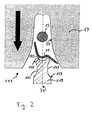
- Fig. 2
- eine schematische Darstellung einer erfindungsgemä- ßen Vorrichtung.
- Fig. 3a und 3b
- jeweils einen vergrößerten Ausschnitt der
Fig. 1 bzw. 2.
- Fig. 1
- 1 is a schematic representation of a device for striking a line to a connecting element according to the prior art,
- Fig. 2
- a schematic representation of an inventive device.
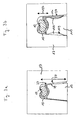
- Fig. 3a and 3b
- each an enlarged section of the
Fig. 1 or 2.
Die Leitung 13 kann mehrere Leitungslitzen umfassen. Das Verbindungselement 15 ist beispielhaft als eine Aderkralle dargestellt, so dass durch das Anschlagen der Leitung an die Aderkralle ein so genannter Adercrimp erzeugt wird. Mittels der Vorrichtung 11 kann jedoch beispielsweise auch ein Isolationscrimp erzeugt werden, bei dem zwischen dem Verbindungselement und dem Leiter isolierendes Material vorgesehen ist.The
Das Obergesenk 17 wird durch eine Presskraft, die in Richtung des Pfeils 25 wirkt, gegen das Untergesenk 19 gepresst. Dadurch werden die Leitung 13 und das Verbindungselement 15 plastisch verformt, und es entsteht eine dauerhafte, nicht mehr lösbare Verbindung zwischen diesen.The
Ein fehlerhaftes Anschlagen der Leitung 13 an das Verbindungselement 15 tritt beispielsweise dann auf, wenn dessen rechte Hälfte 15a, wie in
Ein fehlerhaftes Anschlagen der Leitung 13 an das Verbindungselement 15 kann außer durch ein verbogenes Verbindungselement 15, wie es in
Durch die Aussparungen 133 ist das Untergesenk 119 unterhalb der Pressfläche 123 verjüngt, und die Breite des Untergesenks 119 ist im Bereich der Pressfläche 123 größer als im Bereich der Verjüngung. Die Aussparungen 133 sind muldenförmig ausgebildet und weisen abgerundete Kanten 135 auf, um das Eintreten des fehlgeleiteten Materials in die Aussparung 133 zu erleichtern. Ferner bestehen dadurch keine erhöhten Anforderungen an die Kantenfestigkeit des Materials, aus dem das Untergesenk 119 gefertigt wird.Through the
Die Tiefe der muldenförmigen Aussparungen 133 ist erheblich geringer als ihre Länge längs der jeweiligen Seitenfläche 129. Wenn das fehlgeleitete Material in die Aussparung 133 eintritt und sich in dieser ausbreitet, werden dadurch nur tangentiale Kräfte und keine Normalkräfte auf die Seitenflächen 129 des Untergesenks 119 ausgeübt. Das Volumen, das durch die Aussparungen 133 zwischen dem Untergesenk 119 und dem Obergesenk 17 definiert wird, ist vorzugsweise derart gewählt, dass genügend fehlgeleitetes Material in den Aussparungen 133 aufgenommen werden kann. Das durch die beiden Aussparungen 133 definierte Volumen kann beispielsweise dem Volumen des Verbindungselements 15 entsprechen.The depth of the trough-shaped
Da das fehlgeleitete Material in die Aussparungen 133 aufgenommen wird, werden geringere Kräfte auf die Seitenflächen 129 und 27 des Untergesenks 119 bzw. des Obergesenks 17 ausgeübt, als dies bei der Verwendung eines in
Die Verringerung der Kräfte, die auf die Seitenflächen 27, 29 und 129 des Ober- und Untergesenks 17, 19 bzw. 119 wirken, wird in
Das fehlgeleitete Material wird in
Durch den verkürzten Hebelarm 137 werden die mechanischen Spannungen innerhalb des Obergesenks 17 und des Untergesenks 119 verringert. Folglich wird die Wahrscheinlichkeit kleiner, dass eine Beschädigung des Ober- und/oder Untergesenks 17 bzw. 119 im Falle eines fehlerhaften Anschlagens der Leitung 13 an das Verbindungselement 15 auftritt. Ferner werden die Seiten- und Pressflächen 27, 129, 21 und 123 durch die geringeren mechanischen Spannungen weniger stark beansprucht, so dass die Ausbildung von Riefen insbesondere auf den Flächen 27 bzw. 123 weniger wahrscheinlich ist. Somit wird die Lebensdauer des Obergesenks 17 und des Untergesenks 119 durch die Aussparung 133 insgesamt verlängert, so dass größere Stückzahlen von Crimpverbindungen hergestellt werden können, ohne das Ober- und/oder Untergesenk 17 bzw. 119 austauschen zu müssen.The shortened
- 11, 11111, 111
- Vorrichtungdevice
- 1313
- Leitungmanagement
- 1515
- Verbindungselementconnecting element
- 15a15a
- Abschnitt des VerbindungselementsSection of the connecting element
- 1717
- Obergesenkupper die
- 19, 11919, 119
- Untergesenklower die
- 2121
- Pressfläche des ObergesenksPress surface of the upper die
- 23, 12323, 123
- Pressfläche des UntergesenksPressing surface of the lower part
- 2525
- Pfeil, Richtung der PresskraftArrow, direction of pressing force
- 2727
- Seitenfläche des ObergesenksSide surface of the upper die
- 29, 12929, 129
- Seitenfläche des UntergesenksSide surface of the lower part
- 3131
- Mittelachse der VorrichtungCenter axis of the device
- 133133
- Aussparungrecess
- 135135
- Kanteedge
- 3737
- Hebelarmlever arm
- 137137
- Hebelarmlever arm
Claims (14)
wobei zwischen dem Obergesenk (17) und dem Untergesenk (119) zumindest eine Aussparung (133) außerhalb der Pressflächen (21, 123) vorgesehen ist, die ausgebildet ist, um einen Teil der Leitung (13) und/oder einen Abschnitt des Verbindungselements (15) aufzunehmen.Device (111) for striking a line (13) to a connecting element (15) having an upper die (17) and a lower die (119) each having a pressing surface (21, 123) around the conduit (13) and the connecting element (15) to press in a predetermined area between the upper die (17) and the lower die (119),
wherein between the upper die (17) and the lower die (119) at least one recess (133) is provided outside the pressing surfaces (21, 123), which is designed to form part of the duct (13) and / or a portion of the connecting element (13). 15).
dadurch gekennzeichnet, dass
der Abstand zwischen einer der Pressflächen (21, 123) und zumindest einer Kante (135) der Aussparung (133) geringer als die Länge, Breite und Tiefe der Aussparung (133) ist.Device according to claim 1,
characterized in that
the distance between one of the pressing surfaces (21, 123) and at least one edge (135) of the recess (133) is less than the length, width and depth of the recess (133).
dadurch gekennzeichnet, dass
die Aussparung (133) muldenförmig ausgebildet ist.Apparatus according to claim 1 or 2,
characterized in that
the recess (133) is formed trough-shaped.
dadurch gekennzeichnet, dass
die Aussparung (133) abgerundete Kanten (135) aufweist.Device according to at least one of the preceding claims,
characterized in that
the recess (133) has rounded edges (135).
dadurch gekennzeichnet, dass
die Tiefe der Aussparung (133) geringer als die Länge und die Breite der Aussparung (133) ist.Device according to at least one of the preceding claims,
characterized in that
the depth of the recess (133) is less than the length and the width of the recess (133).
dadurch gekennzeichnet, dass
zumindest zwei symmetrisch zu den Pressflächen (21, 123) angeordnete Aussparungen (133) vorgesehen sind.Device according to at least one of the preceding claims,
characterized in that
at least two symmetrically to the pressing surfaces (21, 123) arranged recesses (133) are provided.
dadurch gekennzeichnet, dass
die Aussparung (133) auf einer Seitenfläche (129) des Untergesenks (119) angeordnet ist.Device according to at least one of the preceding claims,
characterized in that
the recess (133) is disposed on a side surface (129) of the lower die (119).
dadurch gekennzeichnet, dass
das Untergesenk (119) zumindest eine weitere außerhalb der Pressfläche (123) vorgesehene Aussparung (133) aufweist.Device according to at least one of the preceding claims,
characterized in that
the lower die (119) has at least one further recess (133) provided outside the pressing surface (123).
dadurch gekennzeichnet, dass
das Untergesenk (119) unterhalb der Pressfläche (123) eine Verjüngung aufweist, und dass die Breite des Untergesenks (119) im Bereich der Pressfläche (123) größer als im Bereich der Verjüngung ist.Device according to at least one of the preceding claims,
characterized in that
the lower die (119) below the pressing surface (123) has a taper, and that the width of the lower die (119) in the region of the pressing surface (123) is greater than in the region of the taper.
dadurch gekennzeichnet, dass
eine Aussparung (133) auf einer Seitenfläche (27) des Obergesenks (17) angeordnet ist.Device according to at least one of the preceding claims,
characterized in that
a recess (133) is disposed on a side surface (27) of the upper die (17).
dadurch gekennzeichnet, dass
das Obergesenk (17) zumindest eine weitere außerhalb der Pressfläche (21) angeordnete Aussparung (133) aufweist.Device according to at least one of the preceding claims,
characterized in that
the upper die (17) has at least one further recess (133) arranged outside the pressing surface (21).
dadurch gekennzeichnet, dass
das Untergesenk (119) zumindest eine Aussparung (133) außerhalb einer Pressfläche (123) aufweist, um während eines Anschlagens einer Leitung (13) an ein Verbindungselement (15) einen Teil der Leitung (13) und/ oder einen Abschnitt des Verbindungselements (15) aufzunehmen.A lower die (119) for a device (111) according to at least one of the preceding claims,
characterized in that
the lower die (119) has at least one recess (133) outside a pressing surface (123) in order, during abutment of a line (13) on a connecting element (15), a part of the line (13) and / or a part of the connecting element (15 ).
dadurch gekennzeichnet, dass
das Obergesenk (17) zumindest eine Aussparung (133) außerhalb einer Pressfläche (21) aufweist, um während eines Anschlagens einer Leitung (13) an ein Verbindungselement (15) einen Teil der Leitung (13) und/oder einen Abschnitt des Verbindungselements (15) aufzunehmen.Upper die (17) for a device according to at least one of claims 1 to 11,
characterized in that
the upper die (17) has at least one recess (133) outside a pressing surface (21) in order, during abutment of a line (13) on a connecting element (15), a part of the line (13) and / or a part of the connecting element (15 ).
die Leitung (13) und das Verbindungselement (15) in einem vorbestimmten Bereich zwischen jeweils einer Pressfläche (21, 123) eines Obergesenks (17) und eines Untergesenks (119) gepresst werden, und
ein Teil der Leitung (13) und/oder ein Abschnitt des Verbindungselements (15) , wenn dieser den Bereich zwischen den Pressflächen (21, 123) verlässt, in eine zwischen dem Obergesenk (17) und dem Untergesenk (119) außerhalb der Pressflächen (21, 123) vorgesehene Aussparung (133) aufgenommen wird, um eine Beschädigung des Obergesenks (17) und/oder des Untergesenks (119) zu vermeiden.Method for striking a line (13) to a connecting element (15), in which method
the line (13) and the connecting element (15) in a predetermined area between each one pressing surface (21, 123) an upper die (17) and a lower die (119) are pressed, and
a portion of the conduit (13) and / or a portion of the connecting member (15) as it leaves the area between the pressing surfaces (21, 123), into one between the upper die (17) and the lower die (119) outside the pressing surfaces (13) 21, 123) is received in order to avoid damage to the upper die (17) and / or the lower die (119).
Priority Applications (6)
| Application Number | Priority Date | Filing Date | Title |
|---|---|---|---|
| EP09003761.5A EP2230732B1 (en) | 2009-03-16 | 2009-03-16 | Device for attaching a cable to a connection element |
| US13/203,859 US8813341B2 (en) | 2009-03-16 | 2010-02-23 | Device for attaching a line to a connecting element |
| KR1020117023738A KR101662555B1 (en) | 2009-03-16 | 2010-02-23 | Device for attaching a line to a connecting element |
| PCT/EP2010/001149 WO2010105729A1 (en) | 2009-03-16 | 2010-02-23 | Device for attaching a line to a connecting element |
| CN201080011010.5A CN102341973B (en) | 2009-03-16 | 2010-02-23 | Device for attaching line to connecting element |
| JP2012500100A JP5350533B2 (en) | 2009-03-16 | 2010-02-23 | Fixing device for wires and connecting elements |
Applications Claiming Priority (1)
| Application Number | Priority Date | Filing Date | Title |
|---|---|---|---|
| EP09003761.5A EP2230732B1 (en) | 2009-03-16 | 2009-03-16 | Device for attaching a cable to a connection element |
Publications (2)
| Publication Number | Publication Date |
|---|---|
| EP2230732A1 true EP2230732A1 (en) | 2010-09-22 |
| EP2230732B1 EP2230732B1 (en) | 2014-04-23 |
Family
ID=40602306
Family Applications (1)
| Application Number | Title | Priority Date | Filing Date |
|---|---|---|---|
| EP09003761.5A Not-in-force EP2230732B1 (en) | 2009-03-16 | 2009-03-16 | Device for attaching a cable to a connection element |
Country Status (6)
| Country | Link |
|---|---|
| US (1) | US8813341B2 (en) |
| EP (1) | EP2230732B1 (en) |
| JP (1) | JP5350533B2 (en) |
| KR (1) | KR101662555B1 (en) |
| CN (1) | CN102341973B (en) |
| WO (1) | WO2010105729A1 (en) |
Families Citing this family (2)
| Publication number | Priority date | Publication date | Assignee | Title |
|---|---|---|---|---|
| DE102010022925B4 (en) * | 2010-06-07 | 2019-03-07 | Tdk Electronics Ag | Piezoelectric multilayer component and method for forming an outer electrode in a piezoelectric multilayer component |
| JP6421737B2 (en) * | 2015-10-21 | 2018-11-14 | 株式会社オートネットワーク技術研究所 | Manufacturing method of electric wire with terminal, crimping jig, and electric wire with terminal |
Citations (4)
| Publication number | Priority date | Publication date | Assignee | Title |
|---|---|---|---|---|
| US3010183A (en) * | 1956-11-23 | 1961-11-28 | Amp Inc | Method and apparatus for forming a crimped connection |
| JPH0714658A (en) * | 1993-06-22 | 1995-01-17 | Sumitomo Wiring Syst Ltd | Terminal crimper device and terminal crimping method |
| US5500999A (en) * | 1992-07-24 | 1996-03-26 | Yazaki Corporation | Terminal crimping device |
| US20080141753A1 (en) | 2006-12-14 | 2008-06-19 | Intelligent Design Group, Inc. | Method and apparatus for securing connecting ferrules |
Family Cites Families (26)
| Publication number | Priority date | Publication date | Assignee | Title |
|---|---|---|---|---|
| US2535013A (en) * | 1946-03-20 | 1950-12-19 | Aircraft Marine Prod Inc | Electrical connector |
| NL173046B (en) * | 1951-10-11 | Spanset Inter Ag | END PLATE FOR A LIFTING SLING. | |
| US2789278A (en) * | 1953-05-01 | 1957-04-16 | Controls Company | Electrical connection and method of making the same |
| NL120485C (en) * | 1960-03-09 | |||
| JPS5133885A (en) * | 1974-09-14 | 1976-03-23 | Minoru Mizuno | DENSENTODENSENTOOSETSUZOKUSURU HOHO OYOBI SONOSOCHI |
| GB8722564D0 (en) * | 1987-09-25 | 1987-11-04 | Amp Gmbh | Wire insertion tooling assembly |
| US5528815A (en) * | 1990-04-03 | 1996-06-25 | Webb; Edward L. T. | Clinching tool for sheet metal joining |
| US5099570A (en) * | 1991-06-27 | 1992-03-31 | Amp Incorporated | Self aligning inserter |
| US5561267A (en) * | 1993-11-30 | 1996-10-01 | Sumitomo Wiring Systems, Ltd. | Crimp terminal and process for producing the same |
| JPH08315947A (en) * | 1995-05-12 | 1996-11-29 | Yazaki Corp | Pressure contact jig |
| JP3517061B2 (en) * | 1996-09-03 | 2004-04-05 | 矢崎総業株式会社 | Method and apparatus for crimping electric wires |
| CN1208986A (en) * | 1997-08-20 | 1999-02-24 | 博山电机厂 | Stamping connecting method for DC motor winding and commutator |
| DE19737863B4 (en) * | 1997-08-29 | 2015-07-16 | The Whitaker Corp. | Electrical connector and method of making an insulation crimp |
| JP3731783B2 (en) * | 1997-09-05 | 2006-01-05 | 矢崎総業株式会社 | Terminal crimping method and crimping apparatus |
| US6035521A (en) * | 1997-11-18 | 2000-03-14 | General Motors Corporation | Multi-directional crimp plate |
| JP3394179B2 (en) * | 1998-03-03 | 2003-04-07 | 矢崎総業株式会社 | Insulated wire connection structure |
| DE59911369D1 (en) * | 1998-03-25 | 2005-02-03 | Tox Pressotechnik Gmbh | METHOD AND TOOL FOR CONNECTING COMPONENTS WITH ONE PLATE |
| JP2001250657A (en) * | 2000-03-03 | 2001-09-14 | Yazaki Corp | Crimping device for crimping piece of metal terminal fitting |
| US6394833B1 (en) * | 2001-04-25 | 2002-05-28 | Miraco, Inc. | Flat flexible cable connector |
| JP4387612B2 (en) * | 2001-06-13 | 2009-12-16 | 矢崎総業株式会社 | Terminal crimping type |
| JP4878490B2 (en) * | 2006-04-07 | 2012-02-15 | 矢崎総業株式会社 | Terminal crimping apparatus and terminal crimping method |
| JP4846435B2 (en) * | 2006-05-10 | 2011-12-28 | 矢崎総業株式会社 | Terminal bracket and mounting method |
| JP5196535B2 (en) * | 2007-12-20 | 2013-05-15 | 矢崎総業株式会社 | Terminal crimping method for aluminum wires |
| JP5586354B2 (en) * | 2010-07-15 | 2014-09-10 | 矢崎総業株式会社 | Mold and crimping method |
| JP2012048833A (en) * | 2010-08-24 | 2012-03-08 | Auto Network Gijutsu Kenkyusho:Kk | Terminal crimp method and terminal crimp device |
| DE102010051775A1 (en) * | 2010-11-18 | 2012-05-24 | Rosenberger Hochfrequenztechnik Gmbh & Co. Kg | Positive and non-positive crimp connection, in particular for a coaxial connector and crimping tool for this purpose |
-
2009
- 2009-03-16 EP EP09003761.5A patent/EP2230732B1/en not_active Not-in-force
-
2010
- 2010-02-23 WO PCT/EP2010/001149 patent/WO2010105729A1/en active Application Filing
- 2010-02-23 KR KR1020117023738A patent/KR101662555B1/en active IP Right Grant
- 2010-02-23 JP JP2012500100A patent/JP5350533B2/en not_active Expired - Fee Related
- 2010-02-23 US US13/203,859 patent/US8813341B2/en not_active Expired - Fee Related
- 2010-02-23 CN CN201080011010.5A patent/CN102341973B/en not_active Expired - Fee Related
Patent Citations (4)
| Publication number | Priority date | Publication date | Assignee | Title |
|---|---|---|---|---|
| US3010183A (en) * | 1956-11-23 | 1961-11-28 | Amp Inc | Method and apparatus for forming a crimped connection |
| US5500999A (en) * | 1992-07-24 | 1996-03-26 | Yazaki Corporation | Terminal crimping device |
| JPH0714658A (en) * | 1993-06-22 | 1995-01-17 | Sumitomo Wiring Syst Ltd | Terminal crimper device and terminal crimping method |
| US20080141753A1 (en) | 2006-12-14 | 2008-06-19 | Intelligent Design Group, Inc. | Method and apparatus for securing connecting ferrules |
Also Published As
| Publication number | Publication date |
|---|---|
| JP2012520549A (en) | 2012-09-06 |
| JP5350533B2 (en) | 2013-11-27 |
| CN102341973B (en) | 2015-06-03 |
| EP2230732B1 (en) | 2014-04-23 |
| KR101662555B1 (en) | 2016-10-05 |
| US8813341B2 (en) | 2014-08-26 |
| CN102341973A (en) | 2012-02-01 |
| US20110302763A1 (en) | 2011-12-15 |
| WO2010105729A1 (en) | 2010-09-23 |
| KR20110137352A (en) | 2011-12-22 |
Similar Documents
| Publication | Publication Date | Title |
|---|---|---|
| DE60211880T2 (en) | METHOD AND DEVICE FOR USING A CONNECTOR FOR FLEXIBLE FLAT CABLES | |
| EP3235067B1 (en) | Plug and method to produce this plug | |
| EP2144331B1 (en) | Insulation displacement contact and contacting device | |
| DE69911911T2 (en) | Crimp connection terminal for flexible circuit board and crimp arrangement for cable core | |
| DE102014207206A1 (en) | Electrical wire connection structure and electrical wire connection method | |
| DE102010026379A1 (en) | Crimped fitting, method of forming same and wire with terminal fitting | |
| DE112014001819T5 (en) | Structure and method for connecting a terminal | |
| DE4111054C2 (en) | ||
| DE102019200121A1 (en) | Crimp for connecting wires | |
| EP3625857B1 (en) | Strain and pressure relief means in a plug connector housing | |
| DE102010034789B3 (en) | Connectors | |
| EP1972033A2 (en) | Contact cell for accepting a cable end by means of an insulation piercing connection technique, and method for the production thereof | |
| EP2230732B1 (en) | Device for attaching a cable to a connection element | |
| DE4320539C2 (en) | Line wire connector | |
| EP3717391A1 (en) | Connection element for electrically contacting tension members in a load-bearing belt for an elevator system, and method for assembling the connection element on the belt | |
| EP1493053A1 (en) | Fiber-optic plug comprising crimped knobs | |
| DE102012216895B3 (en) | Method for assembling network conduit that is utilized for transmission of data in computer network in e.g. building, involves placing contacts in attachable element, and gripping attachable element by gripper to twist lines | |
| EP3419121B1 (en) | Method for making an electrical connection and an ultrasonic welding system | |
| DE102019104400A1 (en) | Press-fit contact and method for producing the press-fit | |
| EP3857584B1 (en) | Plug for a profiled safety section and a safety edge | |
| DE102012215652A1 (en) | Pressure sensor with connector with a flexible pin arrangement | |
| EP1063724A1 (en) | Crimp connection | |
| DE102022117760B3 (en) | Electrical contact element | |
| DE102016223475A1 (en) | Connecting arrangement and method for producing a connection arrangement for stranded conductors in a guide | |
| DE102008031686A1 (en) | Improved retaining sleeve of a connector |
Legal Events
| Date | Code | Title | Description |
|---|---|---|---|
| PUAI | Public reference made under article 153(3) epc to a published international application that has entered the european phase |
Free format text: ORIGINAL CODE: 0009012 |
|
| 17P | Request for examination filed |
Effective date: 20091202 |
|
| AK | Designated contracting states |
Kind code of ref document: A1 Designated state(s): AT BE BG CH CY CZ DE DK EE ES FI FR GB GR HR HU IE IS IT LI LT LU LV MC MK MT NL NO PL PT RO SE SI SK TR |
|
| AX | Request for extension of the european patent |
Extension state: AL BA RS |
|
| AKX | Designation fees paid |
Designated state(s): AT BE BG CH CY CZ DE DK EE ES FI FR GB GR HR HU IE IS IT LI LT LU LV MC MK MT NL NO PL PT RO SE SI SK TR |
|
| RIC1 | Information provided on ipc code assigned before grant |
Ipc: H01R 4/18 20060101ALI20120209BHEP Ipc: H01R 43/058 20060101AFI20120209BHEP |
|
| 17Q | First examination report despatched |
Effective date: 20120410 |
|
| GRAP | Despatch of communication of intention to grant a patent |
Free format text: ORIGINAL CODE: EPIDOSNIGR1 |
|
| INTG | Intention to grant announced |
Effective date: 20131023 |
|
| GRAS | Grant fee paid |
Free format text: ORIGINAL CODE: EPIDOSNIGR3 |
|
| GRAA | (expected) grant |
Free format text: ORIGINAL CODE: 0009210 |
|
| AK | Designated contracting states |
Kind code of ref document: B1 Designated state(s): AT BE BG CH CY CZ DE DK EE ES FI FR GB GR HR HU IE IS IT LI LT LU LV MC MK MT NL NO PL PT RO SE SI SK TR |
|
| REG | Reference to a national code |
Ref country code: GB Ref legal event code: FG4D Free format text: NOT ENGLISH |
|
| REG | Reference to a national code |
Ref country code: CH Ref legal event code: EP |
|
| REG | Reference to a national code |
Ref country code: AT Ref legal event code: REF Ref document number: 664325 Country of ref document: AT Kind code of ref document: T Effective date: 20140515 |
|
| REG | Reference to a national code |
Ref country code: IE Ref legal event code: FG4D Free format text: LANGUAGE OF EP DOCUMENT: GERMAN |
|
| REG | Reference to a national code |
Ref country code: DE Ref legal event code: R096 Ref document number: 502009009222 Country of ref document: DE Effective date: 20140612 |
|
| REG | Reference to a national code |
Ref country code: NL Ref legal event code: VDEP Effective date: 20140423 |
|
| REG | Reference to a national code |
Ref country code: LT Ref legal event code: MG4D |
|
| PG25 | Lapsed in a contracting state [announced via postgrant information from national office to epo] |
Ref country code: NO Free format text: LAPSE BECAUSE OF FAILURE TO SUBMIT A TRANSLATION OF THE DESCRIPTION OR TO PAY THE FEE WITHIN THE PRESCRIBED TIME-LIMIT Effective date: 20140723 Ref country code: LT Free format text: LAPSE BECAUSE OF FAILURE TO SUBMIT A TRANSLATION OF THE DESCRIPTION OR TO PAY THE FEE WITHIN THE PRESCRIBED TIME-LIMIT Effective date: 20140423 Ref country code: GR Free format text: LAPSE BECAUSE OF FAILURE TO SUBMIT A TRANSLATION OF THE DESCRIPTION OR TO PAY THE FEE WITHIN THE PRESCRIBED TIME-LIMIT Effective date: 20140724 Ref country code: IS Free format text: LAPSE BECAUSE OF FAILURE TO SUBMIT A TRANSLATION OF THE DESCRIPTION OR TO PAY THE FEE WITHIN THE PRESCRIBED TIME-LIMIT Effective date: 20140823 Ref country code: FI Free format text: LAPSE BECAUSE OF FAILURE TO SUBMIT A TRANSLATION OF THE DESCRIPTION OR TO PAY THE FEE WITHIN THE PRESCRIBED TIME-LIMIT Effective date: 20140423 Ref country code: BG Free format text: LAPSE BECAUSE OF FAILURE TO SUBMIT A TRANSLATION OF THE DESCRIPTION OR TO PAY THE FEE WITHIN THE PRESCRIBED TIME-LIMIT Effective date: 20140723 Ref country code: NL Free format text: LAPSE BECAUSE OF FAILURE TO SUBMIT A TRANSLATION OF THE DESCRIPTION OR TO PAY THE FEE WITHIN THE PRESCRIBED TIME-LIMIT Effective date: 20140423 Ref country code: CY Free format text: LAPSE BECAUSE OF FAILURE TO SUBMIT A TRANSLATION OF THE DESCRIPTION OR TO PAY THE FEE WITHIN THE PRESCRIBED TIME-LIMIT Effective date: 20140423 |
|
| PG25 | Lapsed in a contracting state [announced via postgrant information from national office to epo] |
Ref country code: ES Free format text: LAPSE BECAUSE OF FAILURE TO SUBMIT A TRANSLATION OF THE DESCRIPTION OR TO PAY THE FEE WITHIN THE PRESCRIBED TIME-LIMIT Effective date: 20140423 Ref country code: HR Free format text: LAPSE BECAUSE OF FAILURE TO SUBMIT A TRANSLATION OF THE DESCRIPTION OR TO PAY THE FEE WITHIN THE PRESCRIBED TIME-LIMIT Effective date: 20140423 Ref country code: PL Free format text: LAPSE BECAUSE OF FAILURE TO SUBMIT A TRANSLATION OF THE DESCRIPTION OR TO PAY THE FEE WITHIN THE PRESCRIBED TIME-LIMIT Effective date: 20140423 Ref country code: LV Free format text: LAPSE BECAUSE OF FAILURE TO SUBMIT A TRANSLATION OF THE DESCRIPTION OR TO PAY THE FEE WITHIN THE PRESCRIBED TIME-LIMIT Effective date: 20140423 Ref country code: SE Free format text: LAPSE BECAUSE OF FAILURE TO SUBMIT A TRANSLATION OF THE DESCRIPTION OR TO PAY THE FEE WITHIN THE PRESCRIBED TIME-LIMIT Effective date: 20140423 |
|
| PG25 | Lapsed in a contracting state [announced via postgrant information from national office to epo] |
Ref country code: PT Free format text: LAPSE BECAUSE OF FAILURE TO SUBMIT A TRANSLATION OF THE DESCRIPTION OR TO PAY THE FEE WITHIN THE PRESCRIBED TIME-LIMIT Effective date: 20140825 |
|
| REG | Reference to a national code |
Ref country code: DE Ref legal event code: R097 Ref document number: 502009009222 Country of ref document: DE |
|
| PG25 | Lapsed in a contracting state [announced via postgrant information from national office to epo] |
Ref country code: SK Free format text: LAPSE BECAUSE OF FAILURE TO SUBMIT A TRANSLATION OF THE DESCRIPTION OR TO PAY THE FEE WITHIN THE PRESCRIBED TIME-LIMIT Effective date: 20140423 Ref country code: DK Free format text: LAPSE BECAUSE OF FAILURE TO SUBMIT A TRANSLATION OF THE DESCRIPTION OR TO PAY THE FEE WITHIN THE PRESCRIBED TIME-LIMIT Effective date: 20140423 Ref country code: RO Free format text: LAPSE BECAUSE OF FAILURE TO SUBMIT A TRANSLATION OF THE DESCRIPTION OR TO PAY THE FEE WITHIN THE PRESCRIBED TIME-LIMIT Effective date: 20140423 Ref country code: EE Free format text: LAPSE BECAUSE OF FAILURE TO SUBMIT A TRANSLATION OF THE DESCRIPTION OR TO PAY THE FEE WITHIN THE PRESCRIBED TIME-LIMIT Effective date: 20140423 Ref country code: CZ Free format text: LAPSE BECAUSE OF FAILURE TO SUBMIT A TRANSLATION OF THE DESCRIPTION OR TO PAY THE FEE WITHIN THE PRESCRIBED TIME-LIMIT Effective date: 20140423 |
|
| PLBE | No opposition filed within time limit |
Free format text: ORIGINAL CODE: 0009261 |
|
| STAA | Information on the status of an ep patent application or granted ep patent |
Free format text: STATUS: NO OPPOSITION FILED WITHIN TIME LIMIT |
|
| 26N | No opposition filed |
Effective date: 20150126 |
|
| REG | Reference to a national code |
Ref country code: DE Ref legal event code: R097 Ref document number: 502009009222 Country of ref document: DE Effective date: 20150126 |
|
| PG25 | Lapsed in a contracting state [announced via postgrant information from national office to epo] |
Ref country code: SI Free format text: LAPSE BECAUSE OF FAILURE TO SUBMIT A TRANSLATION OF THE DESCRIPTION OR TO PAY THE FEE WITHIN THE PRESCRIBED TIME-LIMIT Effective date: 20140423 |
|
| PG25 | Lapsed in a contracting state [announced via postgrant information from national office to epo] |
Ref country code: LU Free format text: LAPSE BECAUSE OF FAILURE TO SUBMIT A TRANSLATION OF THE DESCRIPTION OR TO PAY THE FEE WITHIN THE PRESCRIBED TIME-LIMIT Effective date: 20150316 Ref country code: MC Free format text: LAPSE BECAUSE OF FAILURE TO SUBMIT A TRANSLATION OF THE DESCRIPTION OR TO PAY THE FEE WITHIN THE PRESCRIBED TIME-LIMIT Effective date: 20140423 |
|
| REG | Reference to a national code |
Ref country code: CH Ref legal event code: PL |
|
| REG | Reference to a national code |
Ref country code: IE Ref legal event code: MM4A |
|
| PG25 | Lapsed in a contracting state [announced via postgrant information from national office to epo] |
Ref country code: LI Free format text: LAPSE BECAUSE OF NON-PAYMENT OF DUE FEES Effective date: 20150331 Ref country code: CH Free format text: LAPSE BECAUSE OF NON-PAYMENT OF DUE FEES Effective date: 20150331 Ref country code: IE Free format text: LAPSE BECAUSE OF NON-PAYMENT OF DUE FEES Effective date: 20150316 |
|
| REG | Reference to a national code |
Ref country code: FR Ref legal event code: PLFP Year of fee payment: 8 |
|
| REG | Reference to a national code |
Ref country code: AT Ref legal event code: MM01 Ref document number: 664325 Country of ref document: AT Kind code of ref document: T Effective date: 20150316 |
|
| PG25 | Lapsed in a contracting state [announced via postgrant information from national office to epo] |
Ref country code: AT Free format text: LAPSE BECAUSE OF NON-PAYMENT OF DUE FEES Effective date: 20150316 |
|
| PG25 | Lapsed in a contracting state [announced via postgrant information from national office to epo] |
Ref country code: MT Free format text: LAPSE BECAUSE OF FAILURE TO SUBMIT A TRANSLATION OF THE DESCRIPTION OR TO PAY THE FEE WITHIN THE PRESCRIBED TIME-LIMIT Effective date: 20140423 |
|
| REG | Reference to a national code |
Ref country code: FR Ref legal event code: PLFP Year of fee payment: 9 |
|
| PG25 | Lapsed in a contracting state [announced via postgrant information from national office to epo] |
Ref country code: HU Free format text: LAPSE BECAUSE OF FAILURE TO SUBMIT A TRANSLATION OF THE DESCRIPTION OR TO PAY THE FEE WITHIN THE PRESCRIBED TIME-LIMIT; INVALID AB INITIO Effective date: 20090316 |
|
| PG25 | Lapsed in a contracting state [announced via postgrant information from national office to epo] |
Ref country code: BE Free format text: LAPSE BECAUSE OF NON-PAYMENT OF DUE FEES Effective date: 20150331 |
|
| PG25 | Lapsed in a contracting state [announced via postgrant information from national office to epo] |
Ref country code: TR Free format text: LAPSE BECAUSE OF FAILURE TO SUBMIT A TRANSLATION OF THE DESCRIPTION OR TO PAY THE FEE WITHIN THE PRESCRIBED TIME-LIMIT Effective date: 20140423 |
|
| REG | Reference to a national code |
Ref country code: FR Ref legal event code: PLFP Year of fee payment: 10 |
|
| PGFP | Annual fee paid to national office [announced via postgrant information from national office to epo] |
Ref country code: GB Payment date: 20180327 Year of fee payment: 10 |
|
| PGFP | Annual fee paid to national office [announced via postgrant information from national office to epo] |
Ref country code: IT Payment date: 20180322 Year of fee payment: 10 Ref country code: FR Payment date: 20180326 Year of fee payment: 10 |
|
| PG25 | Lapsed in a contracting state [announced via postgrant information from national office to epo] |
Ref country code: MK Free format text: LAPSE BECAUSE OF FAILURE TO SUBMIT A TRANSLATION OF THE DESCRIPTION OR TO PAY THE FEE WITHIN THE PRESCRIBED TIME-LIMIT Effective date: 20140423 |
|
| PGFP | Annual fee paid to national office [announced via postgrant information from national office to epo] |
Ref country code: DE Payment date: 20180328 Year of fee payment: 10 |
|
| REG | Reference to a national code |
Ref country code: DE Ref legal event code: R119 Ref document number: 502009009222 Country of ref document: DE |
|
| GBPC | Gb: european patent ceased through non-payment of renewal fee |
Effective date: 20190316 |
|
| PG25 | Lapsed in a contracting state [announced via postgrant information from national office to epo] |
Ref country code: DE Free format text: LAPSE BECAUSE OF NON-PAYMENT OF DUE FEES Effective date: 20191001 Ref country code: GB Free format text: LAPSE BECAUSE OF NON-PAYMENT OF DUE FEES Effective date: 20190316 |
|
| PG25 | Lapsed in a contracting state [announced via postgrant information from national office to epo] |
Ref country code: IT Free format text: LAPSE BECAUSE OF NON-PAYMENT OF DUE FEES Effective date: 20190316 Ref country code: FR Free format text: LAPSE BECAUSE OF NON-PAYMENT OF DUE FEES Effective date: 20190331 |