JP6421737B2 - Manufacturing method of electric wire with terminal, crimping jig, and electric wire with terminal - Google Patents
Manufacturing method of electric wire with terminal, crimping jig, and electric wire with terminal Download PDFInfo
- Publication number
- JP6421737B2 JP6421737B2 JP2015207201A JP2015207201A JP6421737B2 JP 6421737 B2 JP6421737 B2 JP 6421737B2 JP 2015207201 A JP2015207201 A JP 2015207201A JP 2015207201 A JP2015207201 A JP 2015207201A JP 6421737 B2 JP6421737 B2 JP 6421737B2
- Authority
- JP
- Japan
- Prior art keywords
- wire
- terminal
- bottom plate
- jig
- electric wire
- Prior art date
- Legal status (The legal status is an assumption and is not a legal conclusion. Google has not performed a legal analysis and makes no representation as to the accuracy of the status listed.)
- Active
Links
Images


Classifications
-
- H—ELECTRICITY
- H01—ELECTRIC ELEMENTS
- H01R—ELECTRICALLY-CONDUCTIVE CONNECTIONS; STRUCTURAL ASSOCIATIONS OF A PLURALITY OF MUTUALLY-INSULATED ELECTRICAL CONNECTING ELEMENTS; COUPLING DEVICES; CURRENT COLLECTORS
- H01R43/00—Apparatus or processes specially adapted for manufacturing, assembling, maintaining, or repairing of line connectors or current collectors or for joining electric conductors
- H01R43/04—Apparatus or processes specially adapted for manufacturing, assembling, maintaining, or repairing of line connectors or current collectors or for joining electric conductors for forming connections by deformation, e.g. crimping tool
- H01R43/048—Crimping apparatus or processes
-
- H—ELECTRICITY
- H01—ELECTRIC ELEMENTS
- H01B—CABLES; CONDUCTORS; INSULATORS; SELECTION OF MATERIALS FOR THEIR CONDUCTIVE, INSULATING OR DIELECTRIC PROPERTIES
- H01B13/00—Apparatus or processes specially adapted for manufacturing conductors or cables
-
- H—ELECTRICITY
- H01—ELECTRIC ELEMENTS
- H01B—CABLES; CONDUCTORS; INSULATORS; SELECTION OF MATERIALS FOR THEIR CONDUCTIVE, INSULATING OR DIELECTRIC PROPERTIES
- H01B7/00—Insulated conductors or cables characterised by their form
-
- H—ELECTRICITY
- H01—ELECTRIC ELEMENTS
- H01R—ELECTRICALLY-CONDUCTIVE CONNECTIONS; STRUCTURAL ASSOCIATIONS OF A PLURALITY OF MUTUALLY-INSULATED ELECTRICAL CONNECTING ELEMENTS; COUPLING DEVICES; CURRENT COLLECTORS
- H01R4/00—Electrically-conductive connections between two or more conductive members in direct contact, i.e. touching one another; Means for effecting or maintaining such contact; Electrically-conductive connections having two or more spaced connecting locations for conductors and using contact members penetrating insulation
- H01R4/10—Electrically-conductive connections between two or more conductive members in direct contact, i.e. touching one another; Means for effecting or maintaining such contact; Electrically-conductive connections having two or more spaced connecting locations for conductors and using contact members penetrating insulation effected solely by twisting, wrapping, bending, crimping, or other permanent deformation
- H01R4/18—Electrically-conductive connections between two or more conductive members in direct contact, i.e. touching one another; Means for effecting or maintaining such contact; Electrically-conductive connections having two or more spaced connecting locations for conductors and using contact members penetrating insulation effected solely by twisting, wrapping, bending, crimping, or other permanent deformation by crimping
- H01R4/183—Electrically-conductive connections between two or more conductive members in direct contact, i.e. touching one another; Means for effecting or maintaining such contact; Electrically-conductive connections having two or more spaced connecting locations for conductors and using contact members penetrating insulation effected solely by twisting, wrapping, bending, crimping, or other permanent deformation by crimping for cylindrical elongated bodies, e.g. cables having circular cross-section
- H01R4/184—Electrically-conductive connections between two or more conductive members in direct contact, i.e. touching one another; Means for effecting or maintaining such contact; Electrically-conductive connections having two or more spaced connecting locations for conductors and using contact members penetrating insulation effected solely by twisting, wrapping, bending, crimping, or other permanent deformation by crimping for cylindrical elongated bodies, e.g. cables having circular cross-section comprising a U-shaped wire-receiving portion
- H01R4/185—Electrically-conductive connections between two or more conductive members in direct contact, i.e. touching one another; Means for effecting or maintaining such contact; Electrically-conductive connections having two or more spaced connecting locations for conductors and using contact members penetrating insulation effected solely by twisting, wrapping, bending, crimping, or other permanent deformation by crimping for cylindrical elongated bodies, e.g. cables having circular cross-section comprising a U-shaped wire-receiving portion combined with a U-shaped insulation-receiving portion
-
- H—ELECTRICITY
- H01—ELECTRIC ELEMENTS
- H01R—ELECTRICALLY-CONDUCTIVE CONNECTIONS; STRUCTURAL ASSOCIATIONS OF A PLURALITY OF MUTUALLY-INSULATED ELECTRICAL CONNECTING ELEMENTS; COUPLING DEVICES; CURRENT COLLECTORS
- H01R43/00—Apparatus or processes specially adapted for manufacturing, assembling, maintaining, or repairing of line connectors or current collectors or for joining electric conductors
- H01R43/04—Apparatus or processes specially adapted for manufacturing, assembling, maintaining, or repairing of line connectors or current collectors or for joining electric conductors for forming connections by deformation, e.g. crimping tool
- H01R43/058—Crimping mandrels
-
- H—ELECTRICITY
- H02—GENERATION; CONVERSION OR DISTRIBUTION OF ELECTRIC POWER
- H02G—INSTALLATION OF ELECTRIC CABLES OR LINES, OR OF COMBINED OPTICAL AND ELECTRIC CABLES OR LINES
- H02G1/00—Methods or apparatus specially adapted for installing, maintaining, repairing or dismantling electric cables or lines
- H02G1/14—Methods or apparatus specially adapted for installing, maintaining, repairing or dismantling electric cables or lines for joining or terminating cables
-
- H—ELECTRICITY
- H01—ELECTRIC ELEMENTS
- H01B—CABLES; CONDUCTORS; INSULATORS; SELECTION OF MATERIALS FOR THEIR CONDUCTIVE, INSULATING OR DIELECTRIC PROPERTIES
- H01B7/00—Insulated conductors or cables characterised by their form
- H01B7/0009—Details relating to the conductive cores
Landscapes
- Engineering & Computer Science (AREA)
- Manufacturing & Machinery (AREA)
- Connections Effected By Soldering, Adhesion, Or Permanent Deformation (AREA)
- Manufacturing Of Electrical Connectors (AREA)
- Insulated Conductors (AREA)
- Processing Of Terminals (AREA)
Description
本明細書によって開示される技術は、端子付き電線の製造方法、圧着冶具、および端子付き電線に関する。 The technique disclosed by this specification is related with the manufacturing method of an electric wire with a terminal, a crimping jig, and an electric wire with a terminal.
従来、電線と端子との接続は、電線の端末において露出された芯線に対し、端子に設けられたワイヤバレルを圧着させることにより行われている。このような芯線に対するワイヤバレルの圧着は、圧着治具により行われる。具体的には、基台上に載置されたワイヤバレルに芯線を重ね合わせ、圧着冶具を基台に向かって降下させることにより、ワイヤバレル全体を圧着治具の形状に沿って芯線を包み込むように徐々に変形させるとともに、その先端部を芯線に食い込ませる。 Conventionally, the connection between the electric wire and the terminal is performed by crimping a wire barrel provided at the terminal to the core wire exposed at the end of the electric wire. The crimping of the wire barrel to such a core wire is performed by a crimping jig. Specifically, the core wire is superimposed on the wire barrel placed on the base, and the crimping jig is lowered toward the base so that the entire wire barrel is wrapped around the shape of the crimping jig. The tip part is bitten into the core wire.
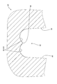
しかしながら、圧着治具を用いてワイヤバレルを芯線に圧着すると、ワイヤバレルのうち圧着治具の端部(端子の軸方向における端部)と当接する部分に応力が集中し、図9および図10示すように、圧縮された芯線100が上方に押し出されるとともに、端子101が局部的に延ばされて、他と比べて薄くなる部分101Tが発生することがあった。
However, when the wire barrel is crimped to the core wire using the crimping jig, stress concentrates on the portion of the wire barrel that contacts the end of the crimping jig (the end in the axial direction of the terminal). As shown, the
本明細書に開示される技術は、端子が部分的に薄くなることが回避された端子付き電線を提供することを目的とする。 An object of the technology disclosed in the present specification is to provide a terminal-attached electric wire in which the terminal is prevented from being partially thinned.
本明細書に開示される技術は、電線の端末において露出した芯線に、底板部と当該底板部から側方に延出された一対のワイヤバレルとを備えた端子が圧着されている端子付き電線の製造方法であって、前記底板部に前記芯線を載置する工程と、圧着治具により前記ワイヤバレルを前記芯線に巻き付けて圧着する工程と、を含み、前記圧着治具は、前記底板部と前記芯線とが載置される載置面を有する第1治具と、前記載置面との間で前記ワイヤバレルを挟みつけて湾曲させる湾曲面を有する第2治具と、を含み、前記湾曲面の表面粗さRa2が前記載置面の表面粗さRa1よりも大(Ra2>Ra1)とされていることを特徴とする。 The technology disclosed in this specification is a wire with a terminal in which a terminal including a bottom plate portion and a pair of wire barrels extending laterally from the bottom plate portion is crimped to a core wire exposed at an end of the wire. The method includes: a step of placing the core wire on the bottom plate portion; and a step of winding the wire barrel around the core wire with a crimping jig and crimping the crimping jig, the crimping jig comprising the bottom plate portion And a first jig having a placement surface on which the core wire is placed, and a second jig having a curved surface that sandwiches and curves the wire barrel between the placement surface, The surface roughness Ra2 of the curved surface is larger than the surface roughness Ra1 of the mounting surface (Ra2> Ra1).
また、電線の端末において露出した芯線に、底板部と当該底板部から側方に延出された一対のワイヤバレルとを備えた端子が圧着されている端子付き電線の製造において、前記一対のワイヤバレルを前記芯線に圧着する圧着治具であって、前記底板部と前記芯線とが載置される載置面を有する第1治具と、前記載置面との間において前記ワイヤバレルを湾曲させる湾曲面を有する第2治具と、を含み、前記湾曲面の表面粗さRa2が前記載置面の表面粗さRa1よりも大(Ra2>Ra1)とされていることを特徴とする。 In the manufacture of a terminal-attached electric wire in which a terminal having a bottom plate portion and a pair of wire barrels extending laterally from the bottom plate portion is crimped to a core wire exposed at an end of the electric wire, the pair of wires A crimping jig for crimping a barrel to the core wire, wherein the wire barrel is bent between the first jig having a placement surface on which the bottom plate portion and the core wire are placed, and the placement surface. And a second jig having a curved surface, wherein the surface roughness Ra2 of the curved surface is greater than the surface roughness Ra1 of the placement surface (Ra2> Ra1).
上記の端子付き電線の製造方法、および、圧着冶具によれば、第2治具の湾曲面の表面粗さRa2が第1治具の載置面の表面粗さRa1よりも大きくされることにより、湾曲面はワイヤバレルに宛がわれた際に、その摩擦力によりワイヤバレル全体に対して滑り難い状態で密着し、ワイヤバレル全体を均一な力で押圧することができる。よって、湾曲面の端縁部(端子の軸方向における端縁部)に応力が集中して端子が部分的に薄くなることが回避され、品質の高い端子付き電線を提供することができる。 According to the manufacturing method of the electric wire with terminal and the crimping jig, the surface roughness Ra2 of the curved surface of the second jig is made larger than the surface roughness Ra1 of the mounting surface of the first jig. When the curved surface is addressed to the wire barrel, the curved surface is brought into close contact with the entire wire barrel in a non-slip state by the friction force, and the entire wire barrel can be pressed with a uniform force. Therefore, it is avoided that stress concentrates on the edge part (edge part in the axial direction of the terminal) of the curved surface and the terminal is partially thinned, and a high-quality electric wire with a terminal can be provided.
湾曲面の表面粗さRa2は0.2≦Ra2≦1.0μmであることが好ましい。Ra2が0.2μmより小さいと、摩擦力が不足して十分な効果が得られない場合があり、1.0μmより大きいと、ワイヤバレルの表面が荒らされる場合があるためである。 The surface roughness Ra2 of the curved surface is preferably 0.2 ≦ Ra2 ≦ 1.0 μm. This is because if Ra2 is smaller than 0.2 μm, the frictional force may be insufficient and a sufficient effect may not be obtained. If Ra2 is larger than 1.0 μm, the surface of the wire barrel may be roughened.
また、上記の端子付き電線の製造方法、および、圧着冶具を用いて製造された端子付き電線は、ワイヤバレルのうち芯線側の面とは反対側のバレル外面の表面粗さRa3が、底板部のうち芯線側の面とは反対側の底板外面の表面粗さRa4よりも大(Ra3>Ra4)とされている。このような端子付き電線は、端子が部分的に薄くなることが回避されており、品質が高い。 In addition, the terminal-attached electric wire manufactured using the above-described method for manufacturing an electric wire with a terminal and a crimping jig has a bottom plate portion with a surface roughness Ra3 on the outer surface of the barrel opposite to the surface on the core wire side of the wire barrel. Of these, the surface roughness Ra4 of the outer surface of the bottom plate opposite to the surface on the core wire side is set to be larger (Ra3> Ra4). Such a terminal-attached electric wire has a high quality because it is avoided that the terminal is partially thinned.
また、本明細書に開示される技術は、電線の端末において露出した芯線に、底板部と当該底板部から側方に延出された一対のワイヤバレルとを備えた端子が圧着されている端子付き電線の製造方法であって、前記底板部に前記芯線を載置する工程と、圧着治具により前記ワイヤバレルを前記芯線に巻き付けて圧着する工程と、を含み、前記圧着治具は、前記底板部と前記芯線とが載置される載置面を有する第1治具と、前記載置面との間で前記ワイヤバレルを挟みつけて湾曲させる湾曲面を有する第2治具と、を含み、前記載置面の表面粗さRa1および前記湾曲面の表面粗さRa2が同等(Ra1=Ra2)とされ、かつ、0.2≦Ra2≦1.0μmとされていることを特徴とする。 The technology disclosed in the present specification is a terminal in which a terminal including a bottom plate portion and a pair of wire barrels extending laterally from the bottom plate portion is crimped to a core wire exposed at an end of an electric wire. A method of manufacturing an attached electric wire, comprising: placing the core wire on the bottom plate portion; and winding and crimping the wire barrel around the core wire with a crimping jig, A first jig having a placement surface on which a bottom plate portion and the core wire are placed; and a second jig having a curved surface that sandwiches and curves the wire barrel between the placement surface. In addition, the surface roughness Ra1 of the mounting surface and the surface roughness Ra2 of the curved surface are equal (Ra1 = Ra2) and 0.2 ≦ Ra2 ≦ 1.0 μm. .
さらに、電線の端末において露出した芯線に、底板部と当該底板部から側方に延出された一対のワイヤバレルとを備えた端子が圧着されている端子付き電線の製造において、前記一対のワイヤバレルを前記芯線に圧着する圧着治具であって、前記底板部と前記芯線とが載置される載置面を有する第1治具と、前記載置面との間において前記ワイヤバレルを湾曲させる湾曲面を有する第2治具と、を含み、前記載置面の表面粗さRa1および前記湾曲面の表面粗さRa2が同等(Ra1=Ra2)とされ、かつ、0.2≦Ra2≦1.0μmとされていることを特徴とする。 Furthermore, in the manufacture of a terminal-attached electric wire in which a terminal having a bottom plate portion and a pair of wire barrels extending laterally from the bottom plate portion is crimped to the core wire exposed at the end of the electric wire, the pair of wires A crimping jig for crimping a barrel to the core wire, wherein the wire barrel is bent between the first jig having a placement surface on which the bottom plate portion and the core wire are placed, and the placement surface. A second jig having a curved surface, wherein the surface roughness Ra1 of the placement surface and the surface roughness Ra2 of the curved surface are equal (Ra1 = Ra2), and 0.2 ≦ Ra2 ≦ It is characterized by being 1.0 μm.
このように、載置面の表面粗さRa1と湾曲面の表面粗さRa2が同等の場合、0.2≦Ra2≦1.0μmの範囲であれば、従来の圧着治具の一般的な表面粗さRa=0.05μmと比較して充分表面粗さが大きいため、摩擦力により圧着治具と端子とが滑ることが抑制される。すなわち、端子に対して部分的に大きな応力がかかることが抑制されるため、品質が高い端子付き電線を得ることができる。 Thus, when the surface roughness Ra1 of the mounting surface is equal to the surface roughness Ra2 of the curved surface, the general surface of the conventional crimping jig is within the range of 0.2 ≦ Ra2 ≦ 1.0 μm. Since the surface roughness is sufficiently large as compared with the roughness Ra = 0.05 μm, the friction between the crimping jig and the terminal is suppressed. That is, since it is suppressed that a big stress is partially applied with respect to a terminal, the electric wire with a terminal with high quality can be obtained.
なお、本明細書に記載される表面粗さRaとは、JIS B 0031・JIS B 0061の付属書で定義されている中心線平均粗さである。 The surface roughness Ra described in the present specification is the centerline average roughness defined in the appendix of JIS B 0031 / JIS B 0061.
本明細書に開示される技術によれば、電線に圧着される圧着部が部分的に薄くなることが回避された端子付き電線を提供することができる。 According to the technology disclosed in this specification, it is possible to provide a terminal-attached electric wire in which a crimping portion to be crimped to the electric wire is avoided from being partially thinned.
<実施形態1>
実施形態1を図1ないし図5によって説明する。以下の説明においては、図1の左下を前方、右上を後方、上を上方、下を下方とする。また、図1の右下から左上を左右方向(幅方向)とする。
<Embodiment 1>
The first embodiment will be described with reference to FIGS. In the following description, the lower left in FIG. 1 is the front, the upper right is the rear, the upper is the upper, and the lower is the lower. Further, the lower right to the upper left in FIG.
本実施形態の端子付き電線10は、圧着冶具30を用いて、電線11の端末に雌端子21を圧着することによって製造される。
The electric wire with
(端子付き電線10)
端子付き電線10は、図1に示すように、電線11と、この電線11の端末に圧着される雌端子21とを有している。
(Wire 10 with terminal)
As shown in FIG. 1, the terminal-attached
(電線11)
電線11は、金属細線を螺旋状に撚り合わせてなる芯線12と、この芯線12を被覆する樹脂製の絶縁被覆13とを有している。電線11の端末部においては、絶縁被覆13が剥き取られて芯線12が露出されている。本実施形態において、芯線12は、アルミニウム製またはアルミニウム合金製である。
(Wire 11)
The
(雌端子21)
雌端子21は、金属板材を打ち抜き加工および曲げ加工して製造された部材である。雌端子21の材料となる金属板材としては、例えば、銅または銅合金製であって表面にスズめっきが施されている板材を用いることができる。
(Female terminal 21)
The
この雌端子21は、図1に示すように、相手側の端子と接続される端子接続部22と、電線11の端末に圧着される電線接続部23とを備えている。端子接続部22は、相手側の端子の雄タブ(図示せず)を内部に受け入れる矩形の筒状の部分である。
As shown in FIG. 1, the
電線接続部23は、端子接続部22から連なる底板24(底板部の一例)と、この底板24から連なる一対のワイヤバレル25と、同じく底板24から連なる一対のインシュレーションバレル29とを備えている。底板24は、端子接続部22の後端から後方に向けて延びる細長い板状の部分であって、電線11に沿って配置されている。
The
一対のワイヤバレル25は、底板24から側方(電線11の延び方向と交差する方向)に向けて延出されており、電線11の端末において絶縁被覆13から露出された芯線12を囲んで配置される部位である。一対のワイヤバレル25は、互いに向かい合って配置されており、底板24との間で芯線12を押し潰すように、芯線12に圧着されている。
The pair of
芯線12に圧着された状態のワイヤバレル25は、前後方向の中央部に配されて芯線12に密着している本体部26と、本体部26の前端部に配され外側に向けて拡がる前方テーパ部28Aと、本体部26の後端部に配され外側に向けて拡がる後方テーパ部28Bとを有している。
The
一対のワイヤバレル25の各本体部26は相手側の本体部26と向かい合って配置され、相手側の本体部26に近づくように芯線12側に向けて湾曲されるとともに、先端部(底板24とは反対側の端部)が芯線12に食い込むように内側に向かって曲げられている。先端部は、相手側の先端部と突き合わせられている。
Each
一方、一対のインシュレーションバレル29は、ワイヤバレル25の後方側において底板24から側方(電線11の延び方向と垂直に交差する方向)に向けて延出されており、電線11の絶縁被覆13に圧着される部位である。
On the other hand, the pair of
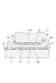
(圧着冶具30)
圧着冶具30は、図2に示すように、アンビル31(第1冶具の一例)と、クリンパ41(第2冶具の一例)とで構成されている。アンビル31は、雌端子21が載置される基台であり、クリンパ41は、アンビル31と対向して配され、アンビル31との間でワイヤバレル25を挟み付けて湾曲させ、芯線12に圧着させる部材である。
(Crimping jig 30)
As illustrated in FIG. 2, the
アンビル31は金属製の基台であって、図2に示すように、その上面が、雌端子21が載置される載置面32となっている。本実施形態において、載置面32は、従来と同様の表面粗さRa1=0.05μmとされている。
The
クリンパ41は、図2に示すように、アンビル31の上方にアンビル31と対向して配置される金属製の厚板状の部材である。クリンパ41は、アンビル31の載置面32と平行に配された下面41Uを有する。
As shown in FIG. 2, the
クリンパ41は、バレル押圧部42を有している。バレル押圧部42は、電線11に雌端子21を圧着する際に、雌端子21およびアンビル31の一部を内部に受け入れる、前後方向に延びるトンネル状の部分であって、下面41Uを基準として上側(アンビル31と反対側)に向かって凹んでいる。
The
バレル押圧部42の内壁は、天壁部43(湾曲面の一例)と、一対の側壁部44と、2つのテーパ壁部48A、48Bとを有している。
The inner wall of the
天壁部43は、下面41Uに対して上方(アンビル31と反対側)に離れて位置する壁部である。天壁部43は、図2および図3に示すように、前後方向に延びる2つのU字溝45を、クリンパ41の幅方向(バレル押圧部42の貫通方向と直交する方向)に並列配置した形状となっている。2つのU字溝45に挟まれた部分は、下方に(アンビル31に向かって)突出し、前後方向に連なって延びる突出部46となっている。
The
一対の側壁部44のそれぞれは、図2および図3に示すように、各U字溝45において、相手側のU字溝45とは反対側の端縁から、下面41Uまで延びる壁部である。一対の側壁部44は、互いに向かい合って配置されている。
As shown in FIGS. 2 and 3, each of the pair of
2つのテーパ壁部48A、48Bのうち前方のテーパ壁部48Aは、図2および図4に示すように、天壁部43および側壁部44から前方に向かって外側に拡がるように延びる壁部であり、後方のテーパ壁部48Bは、図2におよび図4示すように、天壁部43および側壁部44から後方に向かって外側に拡がるように延びる壁部である。
As shown in FIGS. 2 and 4, the front tapered
本実施形態において天壁部43の表面は、粗面化加工が施されることにより、表面粗さRa2=1.0μmの粗面とされている(図3参照)。
In the present embodiment, the surface of the
なお、本実施形態における表面粗さRaとは、JIS B 0031・JIS B 0061の付属書で定義されている中心線平均粗さである。 In addition, surface roughness Ra in this embodiment is centerline average roughness defined by the appendix of JIS B0031 / JIS B0061.
(端子付き電線10の製造方法)
圧着治具30を用いて電線11に雌端子21を圧着する際には、まず、電線11における端末部分の絶縁被覆13を剥がして芯線12の一部を露出させる。この電線11(芯線12および絶縁被覆13)を、雌端子21の底板24に沿わせるようにして前後方向に延ばして配置する(底板24に芯線12を載置する工程)。
(Manufacturing method of
When the
次に、電線11を載置した雌端子21を、アンビル31の載置面32に位置決めして配置する。一対の各ワイヤバレル25は、電線11に圧着される前の状態では平板状となっており、相手側のワイヤバレル25と向かい合う姿勢で、底板24からクリンパ41に向かって立ち上がっている。
Next, the
次いで、クリンパ41をワイヤバレル25に向かって下降させる。すると、一対のワイヤバレル25が、クリンパ41の側壁部44および天壁部43に突き当たり、先端部から徐々に、天壁部43に沿うような形に湾曲していく。クリンパ41がさらに降下していくと、ワイヤバレル25の先端部が芯線12側に向きを変え、芯線12に食い込む。このようにして、芯線12にワイヤバレル25が圧着される(圧着治具30によりワイヤバレル25を芯線12に巻き付けて圧着する工程)。
Next, the
(作用効果)
次に、本実施形態の作用および効果を説明する。
(Function and effect)
Next, the operation and effect of this embodiment will be described.
本実施形態によれば、クリンパ41の天壁部43の表面粗さRa2(1.0μm)がアンビル31の載置面32の表面粗さRa1(0.05μm)よりも大きくされることにより、天壁部43はワイヤバレル25に宛がわれた際に、その摩擦力によりワイヤバレル25全体に対して載置面32よりも滑り難い状態で密着し、ワイヤバレル25全体を均一な力で押圧することができる。よって、ワイヤバレル25のうち天壁部43の前端部および後端部が当接する部分、すなわち、本体部26の前端部および後端部に応力が集中して、底板24が部分的に薄くなることが回避され、品質の高い端子付き電線10が得られる(図5参照)。
According to the present embodiment, the surface roughness Ra2 (1.0 μm) of the
また、本実施形態の端子付き電線10は、ワイヤバレル25のうち芯線12側の面とは反対側のバレル外面25Aの表面粗さRa3が、底板24のうち芯線12側の面とは反対側の底板外面24Aの表面粗さRa4よりも大(Ra3>Ra4)とされている。このような端子付き電線10は、雌端子21が部分的に薄くなることが回避されており、品質が高い。
Further, in the electric wire with
<実施形態2>
実施形態2を図6および図7により説明する。本実施形態において、上記実施形態1と重複する部分は説明を省略し、同符号を用いることとする。
<Embodiment 2>
A second embodiment will be described with reference to FIGS. In the present embodiment, the description of the same parts as those in the first embodiment is omitted, and the same reference numerals are used.
本実施形態の端子付き電線の製造方法および圧着治具は、クリンパ41の天壁部43の表面粗さRa2が、アンビル31の載置面32の表面粗さRa1と同等とされ、かつRa1=Ra2=1.0μmとされたところが上記実施形態と相違している(図6参照)。
In the manufacturing method and crimping jig of the electric wire with terminal of the present embodiment, the surface roughness Ra2 of the
本実施形態のように、載置面32の表面粗さRa1と天壁部43の表面粗さRa2が同等の場合でも、Ra1=Ra2=1.0μmであれば、従来の圧着治具の一般的な表面粗さRa=0.05μmと比較して充分表面粗さが大きいため、摩擦力により圧着治具とワイヤバレル25とが滑ることが抑制される。よって、雌端子21に対して部分的に大きな応力がかかって底板24薄くなることが抑制され、品質が高い端子付き電線10を得ることができる(図7参照)。
Even in the case where the surface roughness Ra1 of the mounting
<実施形態3>
実施形態3は、実施形態1とほぼ同様であるが、天壁部43の表面粗さRa2が実施形態1とは異なる。すなわち本実施形態では、天壁部43の表面粗さRa2=0.2μmとされ、載置面32の表面粗さRa1は従来と同様の0.05μmとされたものである。このような実施形態3においても、雌端子21に対して部分的に大きな応力がかかって底板24が薄くなることが抑制され、品質が高い端子付き電線10を得ることができる(図8参照)。
<Embodiment 3>
The third embodiment is substantially the same as the first embodiment, but the surface roughness Ra2 of the
(結論)
このように、上記実施形態1〜3のいずれにおいてもよい結果が得られた。すなわち、天壁部43の表面粗さRa2が0.2≦Ra2≦1.0μmであれば、摩擦力により圧着治具とワイヤバレル25とが滑ることが抑制され、品質が高い端子付き電線10が得られることがわかった。なお、Ra2が0.2μmより小さいと、摩擦力が不足して十分な滑り抑制効果が得られない場合があり(図10参照)、1.0μmより大きいとワイヤバレルの表面が荒らされる場合があるため、0.2≦Ra2≦1.0μmの範囲内が好適である。
(Conclusion)
Thus, good results were obtained in any of Embodiments 1 to 3 above. That is, if the surface roughness Ra2 of the
<他の実施形態>
本明細書により開示される技術は上記記述及び図面によって説明した実施形態に限定されるものではなく、例えば次のような実施形態も技術的範囲に含まれる。
<Other embodiments>
The technology disclosed in this specification is not limited to the embodiments described with reference to the above description and drawings. For example, the following embodiments are also included in the technical scope.
(1)上記実施形態においては、電線11に圧着する端子は筒状の端子接続部22を有する雌端子21としたが、これに限られず、雄タブを有する雄端子としてもよいし、また金属板材に貫通孔が形成されたいわゆるLA端子としてもよく、必要に応じて任意の形状の端子とすることができる。
(1) In the above embodiment, the terminal to be crimped to the
(2)上記実施形態では、芯線12がアルミニウム製またはアルミニウム合金製の電線11を示したが、芯線が銅製、銅合金製またはその他の任意の金属からなる電線であってもよい。
(2) In the said embodiment, although the
(3)上記実施形態では、銅または銅合金製の金属板材にスズめっきが施された材料を用いた雌端子21を示したが、これに限定されない。たとえばアルミニウム、アルミニウム合金等の金属材料からなる金属板材からなる端子であってもよい。まためっき金属としてはスズを用いてもよいし、めっきが施されていないものであっても構わない。
(3) In the above-described embodiment, the
(4)上記実施形態では、載置面32の表面粗さRa1と天壁部43の表面粗さRa2について3種類の組み合わせを例示したが、Ra1、Ra2の組み合わせや大きさは上記実施形態に限るものではなく、例えば、0.2≦Ra2≦1.0μmの範囲外でも、効果が期待できる。
(4) In the above embodiment, three types of combinations are exemplified for the surface roughness Ra1 of the mounting
10…端子付き電線
11…電線
12…芯線
21…雌端子
24…底板部
25…ワイヤバレル
30…圧着治具
31…アンビル(第1治具)
32…載置面
41…クリンパ(第2治具)
43…天壁部(湾曲面)
Ra1、R2…表面粗さ
DESCRIPTION OF
32 ... Mounting
43 ... Top wall (curved surface)
Ra1, R2 ... surface roughness
Claims (7)
前記底板部に前記芯線を載置する工程と、
圧着治具により前記ワイヤバレルを前記芯線に巻き付けて圧着する工程と、を含み、
前記圧着治具は、前記底板部と前記芯線とが載置される載置面を有する第1治具と、前記載置面との間で前記ワイヤバレルを挟みつけて湾曲させる湾曲面を有する第2治具と、を含み、
前記湾曲面の表面粗さRa2が前記載置面の表面粗さRa1よりも大(Ra2>Ra1)とされている端子付き電線の製造方法。 A method for producing a terminal-attached electric wire in which a terminal having a bottom plate portion and a pair of wire barrels extending laterally from the bottom plate portion is crimped to a core wire exposed at an end of an electric wire,
Placing the core wire on the bottom plate,
Winding the wire barrel around the core wire with a crimping jig, and crimping the wire barrel,
The crimping jig includes a first jig having a placement surface on which the bottom plate portion and the core wire are placed, and a curved surface for bending the wire barrel between the placement surface and the first jig. A second jig,
The manufacturing method of the electric wire with a terminal in which surface roughness Ra2 of the said curved surface is made larger (Ra2> Ra1) than surface roughness Ra1 of the said mounting surface.
前記底板部に前記芯線を載置する工程と、
圧着治具により前記ワイヤバレルを前記芯線に巻き付けて圧着する工程と、を含み、
前記圧着治具は、前記底板部と前記芯線とが載置される載置面を有する第1治具と、前記載置面との間で前記ワイヤバレルを挟みつけて湾曲させる湾曲面を有する第2治具と、を含み、
前記載置面の表面粗さRa1および前記湾曲面の表面粗さRa2が同等(Ra1=Ra2)とされ、かつ、0.2≦Ra2≦1.0μmとされている端子付き電線の製造方法。 A method for producing a terminal-attached electric wire in which a terminal having a bottom plate portion and a pair of wire barrels extending laterally from the bottom plate portion is crimped to a core wire exposed at an end of an electric wire,
Placing the core wire on the bottom plate,
Winding the wire barrel around the core wire with a crimping jig, and crimping the wire barrel,
The crimping jig includes a first jig having a placement surface on which the bottom plate portion and the core wire are placed, and a curved surface for bending the wire barrel between the placement surface and the first jig. A second jig,
The manufacturing method of the electric wire with a terminal by which surface roughness Ra1 of the said mounting surface and surface roughness Ra2 of the said curved surface are made equal (Ra1 = Ra2), and are 0.2 <= Ra2 <= 1.0micrometer.
前記底板部と前記芯線とが載置される載置面を有する第1治具と、前記載置面との間において前記ワイヤバレルを湾曲させる湾曲面を有する第2治具と、を含み、
前記湾曲面の表面粗さRa2が前記載置面の表面粗さRa1よりも大(Ra2>Ra1)とされている圧着治具。 In the manufacture of an electric wire with a terminal in which a terminal having a bottom plate portion and a pair of wire barrels extending laterally from the bottom plate portion is crimped to a core wire exposed at an end of the electric wire, the pair of wire barrels is A crimping jig for crimping the core wire,
A first jig having a placement surface on which the bottom plate portion and the core wire are placed; and a second jig having a curved surface that curves the wire barrel between the placement surface,
A crimping jig in which the surface roughness Ra2 of the curved surface is larger than the surface roughness Ra1 of the mounting surface (Ra2> Ra1).
前記底板部と前記芯線とが載置される載置面を有する第1治具と、前記載置面との間において前記ワイヤバレルを湾曲させる湾曲面を有する第2治具と、を含み、
前記載置面の表面粗さRa1および前記湾曲面の表面粗さRa2がと同等(Ra1=Ra2)とされ、かつ、0.2≦Ra2≦1.0μmとされている圧着治具。 In the manufacture of an electric wire with a terminal in which a terminal having a bottom plate portion and a pair of wire barrels extending laterally from the bottom plate portion is crimped to a core wire exposed at an end of the electric wire, the pair of wire barrels is A crimping jig for crimping the core wire,
A first jig having a placement surface on which the bottom plate portion and the core wire are placed; and a second jig having a curved surface that curves the wire barrel between the placement surface,
The pressure-bonding jig in which the surface roughness Ra1 of the mounting surface and the surface roughness Ra2 of the curved surface are equal to each other (Ra1 = Ra2) and 0.2 ≦ Ra2 ≦ 1.0 μm.
前記底板部に配された前記芯線に、前記一対のワイヤバレルが巻き付けられた状態で圧着されており、
前記ワイヤバレルのうち前記芯線側の面とは反対側のバレル外面の表面粗さRa3が、前記底板部のうち前記芯線側の面とは反対側の底板外面の表面粗さRa4よりも大(Ra3>Ra4)とされている端子付き電線。 A terminal-attached electric wire to which a terminal having a bottom plate portion and a pair of wire barrels extending laterally from the bottom plate portion is crimped to the core wire exposed at the end of the electric wire,
The core wire disposed on the bottom plate portion is crimped in a state where the pair of wire barrels are wound,
The surface roughness Ra3 of the barrel outer surface of the wire barrel opposite to the core wire side surface is larger than the surface roughness Ra4 of the bottom plate outer surface of the bottom plate portion opposite to the core wire side surface ( Ra3> Ra4) A terminal-attached electric wire.
Priority Applications (4)
| Application Number | Priority Date | Filing Date | Title |
|---|---|---|---|
| JP2015207201A JP6421737B2 (en) | 2015-10-21 | 2015-10-21 | Manufacturing method of electric wire with terminal, crimping jig, and electric wire with terminal |
| US15/765,010 US10181691B2 (en) | 2015-10-21 | 2016-10-04 | Production method for terminal-equipped electrical wire, crimp tool, and terminal-equipped electrical wire |
| PCT/JP2016/079410 WO2017068963A1 (en) | 2015-10-21 | 2016-10-04 | Production method for terminal-equipped electrical wire, crimp tool, and terminal-equipped electrical wire |
| CN201680061040.4A CN108140999B (en) | 2015-10-21 | 2016-10-04 | Manufacturing method, crimping jig and the electric wire with terminal of electric wire with terminal |
Applications Claiming Priority (1)
| Application Number | Priority Date | Filing Date | Title |
|---|---|---|---|
| JP2015207201A JP6421737B2 (en) | 2015-10-21 | 2015-10-21 | Manufacturing method of electric wire with terminal, crimping jig, and electric wire with terminal |
Publications (3)
| Publication Number | Publication Date |
|---|---|
| JP2017079168A JP2017079168A (en) | 2017-04-27 |
| JP2017079168A5 JP2017079168A5 (en) | 2018-03-15 |
| JP6421737B2 true JP6421737B2 (en) | 2018-11-14 |
Family
ID=58557374
Family Applications (1)
| Application Number | Title | Priority Date | Filing Date |
|---|---|---|---|
| JP2015207201A Active JP6421737B2 (en) | 2015-10-21 | 2015-10-21 | Manufacturing method of electric wire with terminal, crimping jig, and electric wire with terminal |
Country Status (4)
| Country | Link |
|---|---|
| US (1) | US10181691B2 (en) |
| JP (1) | JP6421737B2 (en) |
| CN (1) | CN108140999B (en) |
| WO (1) | WO2017068963A1 (en) |
Families Citing this family (6)
| Publication number | Priority date | Publication date | Assignee | Title |
|---|---|---|---|---|
| JP6421737B2 (en) * | 2015-10-21 | 2018-11-14 | 株式会社オートネットワーク技術研究所 | Manufacturing method of electric wire with terminal, crimping jig, and electric wire with terminal |
| JP2018022641A (en) * | 2016-08-05 | 2018-02-08 | 矢崎総業株式会社 | Terminal crimping apparatus and method of manufacturing terminal crimping wire |
| JP6763346B2 (en) * | 2017-01-23 | 2020-09-30 | 株式会社オートネットワーク技術研究所 | Electromagnetic shield parts and wire harness |
| JP6904147B2 (en) * | 2017-08-01 | 2021-07-14 | 株式会社オートネットワーク技術研究所 | Wire with terminal |
| DE102021112505A1 (en) * | 2021-05-12 | 2022-11-17 | Te Connectivity Germany Gmbh | Crimp contact, crimp connection and method of making a crimp connection |
| JP2024011154A (en) * | 2022-07-14 | 2024-01-25 | 住友電装株式会社 | Ultrasonic junction body |
Family Cites Families (48)
| Publication number | Priority date | Publication date | Assignee | Title |
|---|---|---|---|---|
| USRE24510E (en) * | 1958-08-05 | Electrical connector | ||
| US2600012A (en) * | 1946-06-27 | 1952-06-10 | Aircraft Marine Prod Inc | Electrical connector |
| BE522982A (en) * | 1952-09-24 | |||
| NL120485C (en) * | 1960-03-09 | |||
| US3146519A (en) * | 1961-03-21 | 1964-09-01 | Etc Inc | Method of making electrical connections |
| DE3921990A1 (en) * | 1988-07-08 | 1990-01-11 | Yazaki Corp | PINCH CONNECTOR FOR LADDER AND METHOD FOR PRODUCING A PINCH CONNECTION |
| US4991289A (en) * | 1989-06-23 | 1991-02-12 | Amp Incorporated | Crimping die and crimped electrical connection therefrom |
| US5084963A (en) * | 1990-09-28 | 1992-02-04 | Burndy Corporation | Preconnection deforming die and method of connecting a grounding rod with an electrical cable |
| JPH0645047A (en) * | 1992-07-24 | 1994-02-18 | Yazaki Corp | Terminal caulking device |
| US5414926A (en) * | 1992-10-09 | 1995-05-16 | Sumitomo Wiring Systems, Ltd. | Terminal crimping apparatus |
| JP2747511B2 (en) * | 1992-10-23 | 1998-05-06 | 矢崎総業株式会社 | Terminal crimping machine |
| JPH0680263U (en) * | 1993-04-27 | 1994-11-08 | 矢崎総業株式会社 | Crimp terminal |
| US5561267A (en) * | 1993-11-30 | 1996-10-01 | Sumitomo Wiring Systems, Ltd. | Crimp terminal and process for producing the same |
| JP3221563B2 (en) * | 1997-09-04 | 2001-10-22 | 矢崎総業株式会社 | Terminal fitting and wire connection determination method and terminal fitting |
| DE19737863B4 (en) * | 1997-08-29 | 2015-07-16 | The Whitaker Corp. | Electrical connector and method of making an insulation crimp |
| JP3731783B2 (en) * | 1997-09-05 | 2006-01-05 | 矢崎総業株式会社 | Terminal crimping method and crimping apparatus |
| JP2001250657A (en) * | 2000-03-03 | 2001-09-14 | Yazaki Corp | Crimping device for crimping piece of metal terminal fitting |
| US6658725B1 (en) * | 2000-05-10 | 2003-12-09 | Ford Global Technologies, Llc | Apparatus for forming a crimped electrical joint |
| JP4387612B2 (en) * | 2001-06-13 | 2009-12-16 | 矢崎総業株式会社 | Terminal crimping type |
| EP1503454B1 (en) | 2003-07-30 | 2015-08-05 | Furukawa Electric Co. Ltd. | Terminal crimping structure for aluminium wire and producing method |
| JP2005050736A (en) * | 2003-07-30 | 2005-02-24 | Furukawa Electric Co Ltd:The | Method of manufacturing terminal crimping structure to aluminum wire and aluminum wire with terminal |
| JP4846435B2 (en) * | 2006-05-10 | 2011-12-28 | 矢崎総業株式会社 | Terminal bracket and mounting method |
| US7493791B2 (en) * | 2006-07-27 | 2009-02-24 | Fci Americas Technology, Inc. | Electrical connector crimp die with crimp overlap indicia forming |
| US7409847B2 (en) * | 2006-12-14 | 2008-08-12 | Intelligent Design Group, Inc. | Method and apparatus for securing connecting ferrules |
| JP2008177034A (en) * | 2007-01-18 | 2008-07-31 | Yazaki Corp | Crimping machine |
| JP4951356B2 (en) * | 2007-01-18 | 2012-06-13 | 矢崎総業株式会社 | Crimping machine and terminal fitting with electric wire |
| JP2008177033A (en) * | 2007-01-18 | 2008-07-31 | Yazaki Corp | Terminal crimping device |
| JP4852436B2 (en) * | 2007-01-23 | 2012-01-11 | 矢崎総業株式会社 | Terminal crimping structure and terminal crimping method to copper alloy wire, and wire harness provided with the terminal crimping structure |
| JP4499114B2 (en) * | 2007-01-25 | 2010-07-07 | タイコエレクトロニクスジャパン合同会社 | Terminal crimping method, terminal crimping apparatus, terminal crimping structure, and electrical connector |
| US20080307934A1 (en) * | 2007-06-14 | 2008-12-18 | Rgb Systems, Inc. | Multi-purpose cable crimping tool |
| JP5107693B2 (en) * | 2007-12-21 | 2012-12-26 | タイコエレクトロニクスジャパン合同会社 | Crimping structure and crimping method |
| JP5169502B2 (en) * | 2008-06-03 | 2013-03-27 | 住友電装株式会社 | Splice connection wire and method of manufacturing splice connection wire |
| JP5428789B2 (en) * | 2008-11-19 | 2014-02-26 | 株式会社オートネットワーク技術研究所 | Electric wire with terminal fitting and method of manufacturing electric wire with terminal fitting |
| US9385449B2 (en) * | 2009-02-16 | 2016-07-05 | Carlisle Interconnect Technologies, Inc. | Terminal/connector having integral oxide breaker element |
| EP2230732B1 (en) * | 2009-03-16 | 2014-04-23 | Delphi Technologies, Inc. | Device for attaching a cable to a connection element |
| DE102009001949B4 (en) * | 2009-03-27 | 2011-02-24 | Wezag Gmbh Werkzeugfabrik | Die half and pressing tool |
| JP2011003363A (en) * | 2009-06-17 | 2011-01-06 | Hirose Electric Co Ltd | Crimp terminal structure, and terminal crimping device |
| WO2011004704A1 (en) * | 2009-07-10 | 2011-01-13 | 矢崎総業株式会社 | Terminal crimping device |
| JP2011103262A (en) * | 2009-11-12 | 2011-05-26 | Yazaki Corp | Crimping terminal and method for crimping terminal |
| JP5586354B2 (en) * | 2010-07-15 | 2014-09-10 | 矢崎総業株式会社 | Mold and crimping method |
| DE102010035424A1 (en) * | 2010-08-26 | 2012-03-01 | Audi Ag | Method for connecting an electrical conductor to an electrical contact part |
| DE102010051775A1 (en) * | 2010-11-18 | 2012-05-24 | Rosenberger Hochfrequenztechnik Gmbh & Co. Kg | Positive and non-positive crimp connection, in particular for a coaxial connector and crimping tool for this purpose |
| EP2485343B1 (en) * | 2011-02-02 | 2013-10-16 | Wezag GmbH Werkzeugfabrik | B-crimp die |
| JP5686064B2 (en) * | 2011-07-26 | 2015-03-18 | 住友電装株式会社 | Crimping die and method for manufacturing electric wire with terminal |
| CN104170168B (en) * | 2012-03-15 | 2016-08-24 | 株式会社自动网络技术研究所 | Terminal and the electric wire of band terminal |
| JP5953590B2 (en) * | 2012-03-21 | 2016-07-20 | 矢崎総業株式会社 | Electric wire with crimp terminal and method for crimping crimp terminal to electric wire |
| WO2017032877A1 (en) * | 2015-08-27 | 2017-03-02 | Te Connectivity Germany Gmbh | Crimp indentor, crimping tool and method of producing a crimp indentor |
| JP6421737B2 (en) * | 2015-10-21 | 2018-11-14 | 株式会社オートネットワーク技術研究所 | Manufacturing method of electric wire with terminal, crimping jig, and electric wire with terminal |
-
2015
- 2015-10-21 JP JP2015207201A patent/JP6421737B2/en active Active
-
2016
- 2016-10-04 CN CN201680061040.4A patent/CN108140999B/en active Active
- 2016-10-04 US US15/765,010 patent/US10181691B2/en active Active
- 2016-10-04 WO PCT/JP2016/079410 patent/WO2017068963A1/en active Application Filing
Also Published As
| Publication number | Publication date |
|---|---|
| WO2017068963A1 (en) | 2017-04-27 |
| US20180294612A1 (en) | 2018-10-11 |
| CN108140999B (en) | 2019-11-05 |
| CN108140999A (en) | 2018-06-08 |
| US10181691B2 (en) | 2019-01-15 |
| JP2017079168A (en) | 2017-04-27 |
Similar Documents
| Publication | Publication Date | Title |
|---|---|---|
| JP6421737B2 (en) | Manufacturing method of electric wire with terminal, crimping jig, and electric wire with terminal | |
| JP5311962B2 (en) | Crimp terminal for aluminum wire and method for manufacturing crimp terminal for aluminum wire | |
| JP6422240B2 (en) | Connection structure, wire harness, and connector | |
| JP5920284B2 (en) | Electric wire with terminal | |
| US10483657B2 (en) | Manufacturing method for electric wire having terminal | |
| JP2014187039A5 (en) | ||
| JP4983467B2 (en) | Terminal crimping device, terminal crimped wire manufacturing method, and terminal crimped wire | |
| JP2009301839A (en) | Method of manufacturing terminal-crimping metal mold and electric wire with terminal fitting | |
| JP2009170217A (en) | Crimp-style terminal, and electric wire with terminal and manufacturing method thereof | |
| WO2017212920A1 (en) | Terminal-equipped electric wire | |
| JP2017033776A (en) | Crimp terminal, method of manufacturing the same, electric wire and wiring harness | |
| JP6904147B2 (en) | Wire with terminal | |
| JP2010055937A (en) | Terminal metal fitting and electric wire with terminal metal fitting | |
| JP6376030B2 (en) | Terminal and electric wire with terminal | |
| JP2010097781A (en) | Manufacturing method of electric wire with terminal fitting, and terminal crimping device | |
| WO2017068965A1 (en) | Production method for terminal-equipped electrical wire, crimp tool, and terminal-equipped electrical wire | |
| JP2010055936A (en) | Terminal metal fitting and electric wire with terminal metal fitting | |
| JP2017201577A (en) | Wire with terminal | |
| JP2009037908A (en) | Terminal crimping device, method of manufacturing terminal crimping electric wire, and terminal crimping electric wire | |
| JP2009252449A (en) | Terminal fitting, wire harness, and wire harness manufacturing method | |
| WO2017110449A1 (en) | Method of manufacturing electric wire having terminal, crimp jig, and electric wire with terminal | |
| JP2016146250A (en) | Manufacturing method of terminal fitting with wire, crimping jig, and terminal fitting with wire | |
| JP6650304B2 (en) | Crimp terminal manufacturing method | |
| JP6123105B2 (en) | How to connect crimp terminals and wires | |
| JP6123739B2 (en) | Manufacturing method of electric wire with terminal, electric wire with terminal and crimping jig |
Legal Events
| Date | Code | Title | Description |
|---|---|---|---|
| A621 | Written request for application examination |
Free format text: JAPANESE INTERMEDIATE CODE: A621 Effective date: 20180129 |
|
| A521 | Request for written amendment filed |
Free format text: JAPANESE INTERMEDIATE CODE: A523 Effective date: 20180131 |
|
| TRDD | Decision of grant or rejection written | ||
| A01 | Written decision to grant a patent or to grant a registration (utility model) |
Free format text: JAPANESE INTERMEDIATE CODE: A01 Effective date: 20180918 |
|
| A61 | First payment of annual fees (during grant procedure) |
Free format text: JAPANESE INTERMEDIATE CODE: A61 Effective date: 20181001 |
|
| R150 | Certificate of patent or registration of utility model |
Ref document number: 6421737 Country of ref document: JP Free format text: JAPANESE INTERMEDIATE CODE: R150 |