JP2011103262A - Crimping terminal and method for crimping terminal - Google Patents
Crimping terminal and method for crimping terminal Download PDFInfo
- Publication number
- JP2011103262A JP2011103262A JP2009258534A JP2009258534A JP2011103262A JP 2011103262 A JP2011103262 A JP 2011103262A JP 2009258534 A JP2009258534 A JP 2009258534A JP 2009258534 A JP2009258534 A JP 2009258534A JP 2011103262 A JP2011103262 A JP 2011103262A
- Authority
- JP
- Japan
- Prior art keywords
- conductor
- crimping
- pair
- electric wire
- bottom plate
- Prior art date
- Legal status (The legal status is an assumption and is not a legal conclusion. Google has not performed a legal analysis and makes no representation as to the accuracy of the status listed.)
- Abandoned
Links
Images


Classifications
-
- H—ELECTRICITY
- H01—ELECTRIC ELEMENTS
- H01R—ELECTRICALLY-CONDUCTIVE CONNECTIONS; STRUCTURAL ASSOCIATIONS OF A PLURALITY OF MUTUALLY-INSULATED ELECTRICAL CONNECTING ELEMENTS; COUPLING DEVICES; CURRENT COLLECTORS
- H01R43/00—Apparatus or processes specially adapted for manufacturing, assembling, maintaining, or repairing of line connectors or current collectors or for joining electric conductors
- H01R43/04—Apparatus or processes specially adapted for manufacturing, assembling, maintaining, or repairing of line connectors or current collectors or for joining electric conductors for forming connections by deformation, e.g. crimping tool
- H01R43/048—Crimping apparatus or processes
-
- H—ELECTRICITY
- H01—ELECTRIC ELEMENTS
- H01R—ELECTRICALLY-CONDUCTIVE CONNECTIONS; STRUCTURAL ASSOCIATIONS OF A PLURALITY OF MUTUALLY-INSULATED ELECTRICAL CONNECTING ELEMENTS; COUPLING DEVICES; CURRENT COLLECTORS
- H01R4/00—Electrically-conductive connections between two or more conductive members in direct contact, i.e. touching one another; Means for effecting or maintaining such contact; Electrically-conductive connections having two or more spaced connecting locations for conductors and using contact members penetrating insulation
- H01R4/10—Electrically-conductive connections between two or more conductive members in direct contact, i.e. touching one another; Means for effecting or maintaining such contact; Electrically-conductive connections having two or more spaced connecting locations for conductors and using contact members penetrating insulation effected solely by twisting, wrapping, bending, crimping, or other permanent deformation
- H01R4/18—Electrically-conductive connections between two or more conductive members in direct contact, i.e. touching one another; Means for effecting or maintaining such contact; Electrically-conductive connections having two or more spaced connecting locations for conductors and using contact members penetrating insulation effected solely by twisting, wrapping, bending, crimping, or other permanent deformation by crimping
- H01R4/183—Electrically-conductive connections between two or more conductive members in direct contact, i.e. touching one another; Means for effecting or maintaining such contact; Electrically-conductive connections having two or more spaced connecting locations for conductors and using contact members penetrating insulation effected solely by twisting, wrapping, bending, crimping, or other permanent deformation by crimping for cylindrical elongated bodies, e.g. cables having circular cross-section
- H01R4/184—Electrically-conductive connections between two or more conductive members in direct contact, i.e. touching one another; Means for effecting or maintaining such contact; Electrically-conductive connections having two or more spaced connecting locations for conductors and using contact members penetrating insulation effected solely by twisting, wrapping, bending, crimping, or other permanent deformation by crimping for cylindrical elongated bodies, e.g. cables having circular cross-section comprising a U-shaped wire-receiving portion
-
- H—ELECTRICITY
- H01—ELECTRIC ELEMENTS
- H01R—ELECTRICALLY-CONDUCTIVE CONNECTIONS; STRUCTURAL ASSOCIATIONS OF A PLURALITY OF MUTUALLY-INSULATED ELECTRICAL CONNECTING ELEMENTS; COUPLING DEVICES; CURRENT COLLECTORS
- H01R4/00—Electrically-conductive connections between two or more conductive members in direct contact, i.e. touching one another; Means for effecting or maintaining such contact; Electrically-conductive connections having two or more spaced connecting locations for conductors and using contact members penetrating insulation
- H01R4/10—Electrically-conductive connections between two or more conductive members in direct contact, i.e. touching one another; Means for effecting or maintaining such contact; Electrically-conductive connections having two or more spaced connecting locations for conductors and using contact members penetrating insulation effected solely by twisting, wrapping, bending, crimping, or other permanent deformation
- H01R4/18—Electrically-conductive connections between two or more conductive members in direct contact, i.e. touching one another; Means for effecting or maintaining such contact; Electrically-conductive connections having two or more spaced connecting locations for conductors and using contact members penetrating insulation effected solely by twisting, wrapping, bending, crimping, or other permanent deformation by crimping
- H01R4/188—Electrically-conductive connections between two or more conductive members in direct contact, i.e. touching one another; Means for effecting or maintaining such contact; Electrically-conductive connections having two or more spaced connecting locations for conductors and using contact members penetrating insulation effected solely by twisting, wrapping, bending, crimping, or other permanent deformation by crimping having an uneven wire-receiving surface to improve the contact
-
- H—ELECTRICITY
- H01—ELECTRIC ELEMENTS
- H01R—ELECTRICALLY-CONDUCTIVE CONNECTIONS; STRUCTURAL ASSOCIATIONS OF A PLURALITY OF MUTUALLY-INSULATED ELECTRICAL CONNECTING ELEMENTS; COUPLING DEVICES; CURRENT COLLECTORS
- H01R43/00—Apparatus or processes specially adapted for manufacturing, assembling, maintaining, or repairing of line connectors or current collectors or for joining electric conductors
- H01R43/04—Apparatus or processes specially adapted for manufacturing, assembling, maintaining, or repairing of line connectors or current collectors or for joining electric conductors for forming connections by deformation, e.g. crimping tool
- H01R43/058—Crimping mandrels
Abstract
Description
本発明は、例えば、自動車の電装系に使用される断面U字状の導体圧着部を有したオープンバレルタイプの圧着端子、および、その圧着端子を用いた端子の圧着方法に関する。 The present invention relates to, for example, an open barrel type crimp terminal having a U-shaped conductor crimping portion used in an automobile electrical system, and a terminal crimping method using the crimp terminal.
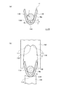
図4は、例えば特許文献1に記載された従来の圧着端子の構成を示す斜視図である。 FIG. 4 is a perspective view showing a configuration of a conventional crimp terminal described in Patent Document 1, for example.
この圧着端子1は、端子の長手方向(接続する電線の導体の長手方向でもある)の前部に、相手コネクタ側の端子に接続される電気接続部10を備え、その後部に、電線(図示略)の端末の露出した導体に加締められる導体圧着部11を備え、さらにその後部に、電線の絶縁被覆の付いた部分に加締められる被覆加締部12を備えている。また、電気接続部10と導体圧着部11の間に、それらの間を繋ぐ第1の繋ぎ部13を備えると共に、導体圧着部11と被覆加締部12の間に、それらの間を繋ぐ第2の繋ぎ部14を備えている。
The crimp terminal 1 includes an
導体圧着部11は、底板11Aと、該底板11Aの左右両側縁から上方に延設されて該底板11Aの内面上に配された電線の導体を包むように加締められる一対の導体加締片11B,11Bとで上方に拡開した断面略U字状に形成されている。また、被覆加締部12は、底板12Aと、該底板12Aの左右両側縁から上方に延設されて該底板12Aの内面上に配された電線(絶縁被覆の付いた部分)を包むように加締められる一対の被覆加締片12B,12Bとで断面略U字状に形成されている。
The
また、導体圧着部11の内面には、電線の導体の長手方向(端子長手方向)と直交する方向に延びる複数本の凹溝状のセレーション18が形成されている。
In addition, a plurality of
この圧着端子1の導体圧着部11を電線の端末の導体に圧着するには、図示しない下型(アンビル)の載置面(上面)上に圧着端子を載せると共に、電線の端末の導体を導体圧着部の導体加締片間に挿入し、図5に示すように、底板11Aの上面に導体Waを載せる。通常、底板11Aから一対の導体加締片11B,11Bの根元までの範囲は、導体Waの半径rよりも大きな曲率半径Rの湾曲壁11Hとして形成されており、そのため導体加締片11A間に導入された導体Waは、導体圧着部11の底板11Aの内面に接触した状態で載る。
In order to crimp the
この状態で、上型(クランパ)を下型に対して相対的に下降させることにより、上型の案内斜面で導体加締片の先端側を徐々に内側に倒して行き、さらに上型(クランパ)を下型に対して相対的に下降させることにより、最終的に、上型の案内斜面から中央の山形部に連なる湾曲面で導体加締片11Bの先端を導体Wa側に折り返すように丸めて、導体加締片11Bの先端同士を擦り合わせながら導体Waに食い込ませることにより、導体Waを包むように導体加締片11Bを加締める。
In this state, the upper die (clamper) is lowered relative to the lower die, and the tip side of the conductor crimping piece is gradually tilted inward by the upper die guide slope. ) Is relatively lowered with respect to the lower die, and finally the tip of the
以上の操作により、圧着端子1の導体圧着部11を電線の導体Waに圧着によって接続することができる。なお、被覆加締部12についても同様に、下型と上型を用いて被覆加締片12Bを内側に徐々に曲げて行き、被覆加締片12Bを電線の絶縁被覆の付いた部分に加締める。こうすることにより、圧着端子1を電線に電気的および機械的に接続することができる。
By the above operation, the
ところで、上述した従来の圧着端子の場合、導体圧着部11の底板11Aから一対の導体加締片11B,11Bの根元までの範囲を構成する湾曲壁11Hの曲率半径Rが、内側に包み込む電線の導体Waの半径rよりも大きくなるように設定されていたので、最終的に圧着状態としたときの端子と導体の接圧があまり高くならず、接触抵抗が不安定になりやすいという問題があった。
By the way, in the case of the conventional crimp terminal described above, the radius of curvature R of the
本発明は、上記事情を考慮し、電線と端子の接圧を高くして、電気的接続性能の向上を図れるようにした圧着端子、および、その圧着端子を用いた端子の圧着方法を提供することを目的とする。 In view of the above circumstances, the present invention provides a crimping terminal capable of improving the electrical connection performance by increasing the contact pressure between the electric wire and the terminal, and a terminal crimping method using the crimping terminal. For the purpose.
上記課題を解決するために、請求項1の発明の圧着端子は、電線の導体の端末に圧着して接続される導体圧着部を有し、該導体圧着部が、底板と、該底板の左右両側縁から上方に延設された一対の導体加締片とで、上方に拡開した断面略U字状に形成され、電線に圧着する際に、前記一対の導体加締片の間に電線の導体を挿入し、その状態で圧着装置の下型と上型の圧着動作により、前記一対の導体加締片を内側に丸めて前記導体を底板との間に包み込むように加締めることで、前記電線と電気的に接続される圧着端子において、前記底板から前記一対の導体加締片の根元にかけての範囲が略円弧状の湾曲壁として形成されており、その湾曲壁の内面の曲率半径をR、前記電線の導体の半径をrとした場合、R<rに設定されていることを特徴としている。 In order to solve the above-mentioned problems, the crimp terminal of the invention of claim 1 has a conductor crimping part that is crimped and connected to the end of the conductor of the electric wire, and the conductor crimping part includes a bottom plate and left and right sides of the bottom plate. A pair of conductor crimping pieces extending upward from both side edges and formed in a substantially U-shaped cross-section expanding upward. In this state, by crimping the lower and upper molds of the crimping device, the pair of conductor crimping pieces are rounded inward and crimped so as to wrap the conductor between the bottom plate, In the crimp terminal electrically connected to the electric wire, a range from the bottom plate to the base of the pair of conductor crimping pieces is formed as a substantially arc-shaped curved wall, and a radius of curvature of the inner surface of the curved wall is set. R, where r is the radius of the conductor of the wire, R <r. It is set to.
請求項2の発明の端子の圧着方法は、請求項1に記載の圧着端子を、圧着装置の上型と下型の間に配置すると共に、前記一対の導体加締片の間に前記電線の導体の端末を挿入し、その状態で前記上型を下型に対して相対的に下動させることにより、前記一対の導体加締片を前記上型の案内斜面の働きにより内側に倒し、さらに前記上型を下型に対して相対的に下動させることにより、前記上型の案内斜面から中央の山形部に連なる湾曲面の働きにより、前記一対の導体加締片を導体側に折り返すように内側に丸めて行き、最終的に前記導体加締片の先端同士を擦り合わせながら導体に食い込ませることで、前記底板との間に導体を包み込むように両導体加締片を加締めることを特徴としている。 According to a method for crimping a terminal according to a second aspect of the present invention, the crimp terminal according to the first aspect is disposed between the upper mold and the lower mold of the crimping apparatus, and the wire is interposed between the pair of conductor crimping pieces. By inserting the end of the conductor and moving the upper die downward relative to the lower die in this state, the pair of conductor crimping pieces are brought down inside by the action of the guide slope of the upper die, and By lowering the upper mold relative to the lower mold, the pair of conductor crimping pieces are folded back to the conductor side by the action of a curved surface that extends from the guide slope of the upper mold to the central chevron. The two conductor crimping pieces are crimped so as to wrap the conductor between the bottom plate by rubbing the conductors while rubbing the ends of the conductor crimping pieces together. It is a feature.
請求項1の発明によれば、湾曲壁(導体圧着部の底板から一対の導体加締片の根元にかけての範囲)の内面の曲率半径Rを、電線の導体の半径rよりも小さく設定してあるので、圧着を行う前に電線の導体を導体加締片の間に挿入した際には、導体は、導体加締片の高さ方向の途中で導体加締片の内面に当たって止まり、導体圧着部の底板に触れない状態に保たれる。この状態から圧着装置の上型を下型に対して相対的に下動させて圧着加工を行うと、一対の導体加締片の先端が上型の案内斜面に接触することで徐々に内側に倒れて行き、さらに上型を下型に対して相対的に下動させることにより、一対の導体加締片の先端が、上型の案内斜面から中央の山形部に連なる湾曲面に当たることで、内側に案内されて導体側に折り返すように丸められて行き、最終的に両導体加締片の先端同士が擦り合いながら導体に食い込んで行くことで、底板との間に導体を包み込むように両導体加締片が加締められる。 According to the invention of claim 1, the radius of curvature R of the inner surface of the curved wall (the range from the bottom plate of the conductor crimping portion to the root of the pair of conductor crimping pieces) is set smaller than the radius r of the conductor of the electric wire. Therefore, when the conductor of the electric wire is inserted between the conductor crimping pieces before crimping, the conductor hits the inner surface of the conductor crimping piece in the height direction of the conductor crimping piece and stops. It is kept in a state where it does not touch the bottom plate. When the upper die of the crimping device is moved downward relative to the lower die from this state and the crimping process is performed, the tip of the pair of conductor crimping pieces comes into contact with the guide slope of the upper die gradually to the inside. By falling down and further moving the upper mold relative to the lower mold, the tips of the pair of conductor crimping pieces hit the curved surface connected to the central chevron from the upper guide slope, It is guided to the inside and rounded so as to be folded back to the conductor side, and finally the both ends of the conductor crimping pieces rub against each other while rubbing against each other, so that both conductors are wrapped between the bottom plate. The conductor crimping piece is crimped.
その一連の動作の際、電線の導体は導体圧着部の底板に押し付けられることになるが、それに伴い湾曲壁(底板から導体加締片の根元にかけての範囲)が導体からの圧力並びに導体加締片からの圧力を受けることによって外側に押し広げられる。そして最終的には、湾曲壁が外側に押し広げられた状態のまま、導体加締片の先端が導体に食い込むように加締められて圧着が完了する。 During the series of operations, the conductor of the electric wire is pressed against the bottom plate of the conductor crimping part, and the curved wall (range from the bottom plate to the base of the conductor crimping piece) moves along with the pressure from the conductor and the conductor crimping. It is pushed outward by receiving pressure from the piece. And finally, crimping is completed by crimping the tip of the conductor crimping piece so as to bite into the conductor while the curved wall is pushed outward.
従って、最終的な圧着状態においては、湾曲壁には、曲率の小さい原形状に戻ろうとする大きなスプリングバック力が発生することになる。特に底板と導体加締片の根元との境界部分(この部分を「ショルダー部」という)に発生するスプリングバック力は、内側に包み込んだ導体に密着しようとする接圧として作用することになるので、それにより、導体と端子の密着性が増して接触抵抗が小さく安定することになり、電気的接続性能の向上が図れる。 Therefore, in the final crimped state, a large springback force is generated on the curved wall to return to the original shape with a small curvature. In particular, the springback force generated at the boundary between the bottom plate and the base of the conductor crimping piece (this part is called the “shoulder part”) acts as a contact pressure that tries to adhere to the conductor wrapped inside. As a result, the adhesion between the conductor and the terminal is increased, the contact resistance is reduced and stabilized, and the electrical connection performance can be improved.
請求項2の発明によれば、請求項1の発明の圧着端子を上型と下型を用いて電線の導体に圧着させるので、端子に対し有効にスプリングバック力を発生させることができて、端子と電線を安定した接触抵抗で接続することができる。 According to the invention of claim 2, since the crimp terminal of the invention of claim 1 is crimped to the conductor of the electric wire using the upper mold and the lower mold, the springback force can be effectively generated against the terminal, The terminal and the electric wire can be connected with a stable contact resistance.
以下、本発明の実施形態を図面を用いて説明する。 Hereinafter, embodiments of the present invention will be described with reference to the drawings.
図1は実施形態の圧着端子の要部構成図で、図1(a)は圧着端子の導体圧着部と電線の導体の関係を示す断面図、図1(b)は導体圧着部を導体に圧着する場合の操作の初期段階を示す図、図2は同圧着端子を導体に圧着させる際の工程説明図であり、図2(a)は導体加締片が内側に倒れ始めた状態を示す導体圧着部の図、図2(b)は導体加締片が内側に丸まり始めた状態を示す図、図2(c)は導体加締片が導体側に折り返すように丸められた状態を示す図、図3は同圧着端子が最終的に導体に圧着された状態を示す断面図である。なお、図中一点鎖線は実施形態の圧着端子の導体圧着部の原形状を誇張して示し、図中二点鎖線は一般的な従来の圧着端子の導体圧着部の原形状を誇張して示している。 FIG. 1 is a configuration diagram of a principal part of a crimp terminal according to an embodiment. FIG. 1A is a cross-sectional view showing a relationship between a conductor crimp part of a crimp terminal and a conductor of an electric wire, and FIG. FIG. 2 is a diagram illustrating an initial stage of operation when crimping, FIG. 2 is a process explanatory diagram when crimping the crimp terminal to a conductor, and FIG. 2 (a) illustrates a state where the conductor crimping piece starts to fall inward. FIG. 2B is a diagram showing a conductor crimping portion, FIG. 2B is a diagram showing a state where a conductor crimping piece starts to be curled inward, and FIG. 2C is a diagram showing a state in which the conductor crimping piece is rolled back to the conductor side. FIG. 3 and FIG. 3 are sectional views showing a state in which the crimp terminal is finally crimped to the conductor. In the figure, the one-dot chain line exaggerates the original shape of the conductor crimping part of the crimp terminal of the embodiment, and the two-dot chain line in the figure exaggerates the original shape of the conductor crimping part of a general conventional crimp terminal. ing.
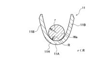
本実施形態の圧着端子においても、図1(a)に示すように、電線の導体Waの端末に圧着接続される導体圧着部11は、底板11Aと、該底板11Aの左右両側縁から上方に延設された一対の導体加締片11B,11Bとで、上方に拡開した断面略U字状に形成されている。そして、底板11Aから一対の導体加締片11B,11Bの根元にかけての範囲が略円弧状の湾曲壁11Hとして形成され、その湾曲壁11Hの内面の曲率半径をR、電線の導体Waの半径をrとした場合、R<rに設定されていることを特徴としている。
Also in the crimp terminal of the present embodiment, as shown in FIG. 1A, the
この圧着端子を電線に圧着する場合は、図1(b)に示すように、圧着装置の上型(クランパ)102と下型(アンビル)101の間に圧着端子の導体圧着部11を配置すると共に、一対の導体加締片11B,11Bの間に電線の導体Waの端末を挿入する。この際、湾曲壁11H(導体圧着部11の底板11Aから一対の導体加締片11B,11Bの根元にかけての範囲)の内面の曲率半径Rが電線の導体の半径rよりも小さく設定されているので、導体Waは、導体加締片11Bの高さ方向の途中で導体加締片11Bの内面に当たって止まり、導体圧着部11の底板11Aに触れない状態に保たれる。つまり、底板11Aの内面と導体Waとの間に隙間Hが空いた状態に保たれる。
When this crimping terminal is crimped to an electric wire, a
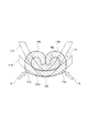
この状態から圧着装置の上型102を下型101に対して相対的に下動させて圧着加工を行うと、図2(a)に示すように、一対の導体加締片11B,11Bの先端が上型102の案内斜面110に接触することで徐々に内側に倒れて行き、さらに上型102を下型101に対して相対的に下動させることにより、図2(b)、(c)に示すように、一対の導体加締片11B,11Bの先端が、上型の案内斜面119から中央の山形部112に連なる湾曲面111に当たることで、内側に案内されて導体Wa側に折り返すように丸められて行き、最終的に図3に示すように、両導体加締片11Bの先端同士が擦り合いながら導体Waに食い込んで行くことで、底板11Aとの間に導体Waを包み込むように両導体加締片11Bが加締められる。
When the
この一連の動作の際、電線の導体Waは導体圧着部11の底板11Aに押し付けられることになるが、それに伴い湾曲壁11H(底板11Aから導体加締片11Bの根元にかけての範囲)が導体Waからの圧力並びに導体加締片11Bからの圧力を受けることによって外側に押し広げられる。そして最終的には、湾曲壁11Hが外側に押し広げられた状態のまま、導体加締片11Bの先端が導体Waに食い込むように加締められて圧着が完了する。
During this series of operations, the conductor Wa of the electric wire is pressed against the
従って、図3に示す最終的な圧着状態においては、湾曲壁11Hには、曲率の小さい原形状(11Yで示す形)に戻ろうとする大きなスプリングバック力が発生することになる。特に底板11Aと導体加締片11Bの根元との境界部分であるショルダー部11Cに発生するスプリングバック力Sは、従来の圧着端子のような曲率の大きい原形状(11Xで示す形)に戻ろうとする場合のスプリングバック力より大きくなり、内側に包み込んだ導体Waに密着しようとする接圧として作用することになるので、それにより、導体Waと端子の密着性が増して接触抵抗が小さく安定することになる。
Therefore, in the final crimped state shown in FIG. 3, a large springback force is generated on the
以上のように、本実施形態の圧着端子を上型102と下型101を用いて電線の導体Waに圧着させた場合、端子に対して有効にスプリングバック力を発生させることができるので、端子と電線を安定した接触抵抗で接続することができることになる。
As described above, when the crimp terminal of the present embodiment is crimped to the conductor Wa of the electric wire using the
11 導体圧着部
11A 底板
11B 導体加締片
11H 湾曲壁
101 下型
102 上型
110 案内斜面
111 湾曲面
112 山形部
Wa 電線の導体
DESCRIPTION OF
Claims (2)
前記底板から前記一対の導体加締片の根元にかけての範囲が略円弧状の湾曲壁として形成されており、その湾曲壁の内面の曲率半径をR、前記電線の導体の半径をrとした場合、R<rに設定されていることを特徴とする圧着端子。 It has a conductor crimping portion that is crimped and connected to the end of the conductor of the electric wire, and the conductor crimping portion includes a bottom plate and a pair of conductor crimping pieces extending upward from the left and right side edges of the bottom plate, It is formed in a substantially U-shaped cross section that expands upward, and when crimping to the electric wire, the conductor of the electric wire is inserted between the pair of conductor crimping pieces, and in this state, the lower die and upper die of the crimping device By crimping, by crimping the pair of conductor crimping pieces inward and wrapping the conductor between the bottom plate, in the crimp terminal electrically connected to the wire,
When the range from the bottom plate to the root of the pair of conductor crimping pieces is formed as a substantially arc-shaped curved wall, the radius of curvature of the inner surface of the curved wall is R, and the radius of the conductor of the wire is r R <r is set to R <r.
前記圧着端子を、圧着装置の上型と下型の間に配置すると共に、前記一対の導体加締片の間に前記電線の導体の端末を挿入し、その状態で前記上型を下型に対して相対的に下動させることにより、前記一対の導体加締片を前記上型の案内斜面の働きにより内側に倒し、さらに前記上型を下型に対して相対的に下動させることにより、前記上型の案内斜面から中央の山形部に連なる湾曲面の働きにより、前記一対の導体加締片を導体側に折り返すように内側に丸めて行き、最終的に前記導体加締片の先端同士を擦り合わせながら導体に食い込ませることで、前記底板との間に導体を包み込むように両導体加締片を加締めることを特徴とする端子の圧着方法。 It has a conductor crimping portion that is crimped and connected to the end of the conductor of the electric wire, and the conductor crimping portion includes a bottom plate and a pair of conductor crimping pieces extending upward from the left and right side edges of the bottom plate, It is formed in a substantially U-shaped cross section that expands upward, and when crimping to the electric wire, the conductor of the electric wire is inserted between the pair of conductor crimping pieces, and in this state, the lower die and upper die of the crimping device In the crimping method of the crimping terminal electrically connected to the electric wire, by crimping the crimping operation so that the pair of conductor crimping pieces are rounded inward and the conductor is wrapped between the bottom plate,
The crimp terminal is disposed between the upper mold and the lower mold of the crimping apparatus, and the end of the conductor of the electric wire is inserted between the pair of conductor crimping pieces, and the upper mold is changed to the lower mold in that state. By moving the pair of conductor crimping pieces inward by the action of the guide slope of the upper mold, and further moving the upper mold downward relative to the lower mold The pair of conductor crimping pieces are rounded inward so as to be folded back to the conductor side by the action of a curved surface extending from the upper guide guide slope to the central chevron, and finally the tip of the conductor crimping piece A terminal crimping method, wherein both conductor crimping pieces are crimped so as to wrap the conductor between the bottom plates by biting the conductors while rubbing each other.
Priority Applications (5)
| Application Number | Priority Date | Filing Date | Title |
|---|---|---|---|
| JP2009258534A JP2011103262A (en) | 2009-11-12 | 2009-11-12 | Crimping terminal and method for crimping terminal |
| US13/508,637 US9048606B2 (en) | 2009-11-12 | 2010-10-25 | Press bond terminal and method for pressing and bonding terminal |
| CN2010800492152A CN102598416A (en) | 2009-11-12 | 2010-10-25 | Crimping terminal and method for crimping terminal |
| EP10829832.4A EP2500980A4 (en) | 2009-11-12 | 2010-10-25 | Crimping terminal and method for crimping terminal |
| PCT/JP2010/068880 WO2011058872A1 (en) | 2009-11-12 | 2010-10-25 | Crimping terminal and method for crimping terminal |
Applications Claiming Priority (1)
| Application Number | Priority Date | Filing Date | Title |
|---|---|---|---|
| JP2009258534A JP2011103262A (en) | 2009-11-12 | 2009-11-12 | Crimping terminal and method for crimping terminal |
Publications (1)
| Publication Number | Publication Date |
|---|---|
| JP2011103262A true JP2011103262A (en) | 2011-05-26 |
Family
ID=43991531
Family Applications (1)
| Application Number | Title | Priority Date | Filing Date |
|---|---|---|---|
| JP2009258534A Abandoned JP2011103262A (en) | 2009-11-12 | 2009-11-12 | Crimping terminal and method for crimping terminal |
Country Status (5)
| Country | Link |
|---|---|
| US (1) | US9048606B2 (en) |
| EP (1) | EP2500980A4 (en) |
| JP (1) | JP2011103262A (en) |
| CN (1) | CN102598416A (en) |
| WO (1) | WO2011058872A1 (en) |
Families Citing this family (5)
| Publication number | Priority date | Publication date | Assignee | Title |
|---|---|---|---|---|
| JP5846114B2 (en) * | 2012-12-19 | 2016-01-20 | 住友電装株式会社 | Manufacturing method of electric wire with terminal and electric wire with terminal |
| WO2014129229A1 (en) | 2013-02-23 | 2014-08-28 | 古河電気工業株式会社 | Cylindrical body, crimping terminal, method for manufacturing said body and said terminal, and device for manufacturing said crimping terminal |
| JP5920284B2 (en) * | 2013-05-17 | 2016-05-18 | 住友電装株式会社 | Electric wire with terminal |
| JP6421737B2 (en) * | 2015-10-21 | 2018-11-14 | 株式会社オートネットワーク技術研究所 | Manufacturing method of electric wire with terminal, crimping jig, and electric wire with terminal |
| JP6713009B2 (en) * | 2018-02-15 | 2020-06-24 | 株式会社オートネットワーク技術研究所 | Terminals and connectors |
Citations (3)
| Publication number | Priority date | Publication date | Assignee | Title |
|---|---|---|---|---|
| JPH05109458A (en) * | 1991-01-25 | 1993-04-30 | Nippon Autom Mach Kk | Caulking device for electric wire terminal |
| JP2002100452A (en) * | 2000-09-22 | 2002-04-05 | Yazaki Corp | Connection method of terminal and electrical wire |
| JP2008177033A (en) * | 2007-01-18 | 2008-07-31 | Yazaki Corp | Terminal crimping device |
Family Cites Families (10)
| Publication number | Priority date | Publication date | Assignee | Title |
|---|---|---|---|---|
| US3032602A (en) * | 1959-12-16 | 1962-05-01 | Gen Motors Corp | Electrical connector |
| US3404368A (en) * | 1965-08-04 | 1968-10-01 | Amp Inc | Electrical connector of the plug or socket variety |
| US4142771A (en) * | 1974-10-16 | 1979-03-06 | Amp Incorporated | Crimp-type terminal |
| US5445535A (en) * | 1994-05-02 | 1995-08-29 | General Motors Corporation | Insulation displacement terminal |
| JP2001217013A (en) | 2000-02-02 | 2001-08-10 | Sumitomo Wiring Syst Ltd | Terminal fitting |
| EP2472674B1 (en) | 2003-07-30 | 2020-09-30 | The Furukawa Electric Co., Ltd. | Terminal crimping method onto aluminum electric-wire |
| JP4250103B2 (en) | 2004-03-12 | 2009-04-08 | Smk株式会社 | Crimping device |
| JP4078564B2 (en) | 2006-06-02 | 2008-04-23 | 住友電装株式会社 | Female terminal fitting |
| JP4983467B2 (en) | 2007-08-02 | 2012-07-25 | 住友電装株式会社 | Terminal crimping device, terminal crimped wire manufacturing method, and terminal crimped wire |
| JP2009258534A (en) | 2008-04-21 | 2009-11-05 | Sharp Corp | Flicker adjustment sheet and flicker adjustment method for display using same |
-
2009
- 2009-11-12 JP JP2009258534A patent/JP2011103262A/en not_active Abandoned
-
2010
- 2010-10-25 CN CN2010800492152A patent/CN102598416A/en active Pending
- 2010-10-25 US US13/508,637 patent/US9048606B2/en not_active Expired - Fee Related
- 2010-10-25 WO PCT/JP2010/068880 patent/WO2011058872A1/en active Application Filing
- 2010-10-25 EP EP10829832.4A patent/EP2500980A4/en not_active Withdrawn
Patent Citations (3)
| Publication number | Priority date | Publication date | Assignee | Title |
|---|---|---|---|---|
| JPH05109458A (en) * | 1991-01-25 | 1993-04-30 | Nippon Autom Mach Kk | Caulking device for electric wire terminal |
| JP2002100452A (en) * | 2000-09-22 | 2002-04-05 | Yazaki Corp | Connection method of terminal and electrical wire |
| JP2008177033A (en) * | 2007-01-18 | 2008-07-31 | Yazaki Corp | Terminal crimping device |
Also Published As
| Publication number | Publication date |
|---|---|
| US9048606B2 (en) | 2015-06-02 |
| EP2500980A1 (en) | 2012-09-19 |
| EP2500980A4 (en) | 2014-12-03 |
| WO2011058872A1 (en) | 2011-05-19 |
| US20120231678A1 (en) | 2012-09-13 |
| CN102598416A (en) | 2012-07-18 |
Similar Documents
| Publication | Publication Date | Title |
|---|---|---|
| US10003136B2 (en) | Crimp terminal and crimping structure with respect to electrical wire thereof | |
| JP2011096451A (en) | Crimping terminal | |
| JP5777357B2 (en) | Crimp terminal | |
| JP5601926B2 (en) | Crimp terminal | |
| JP5890992B2 (en) | Crimp terminal | |
| JP2011096452A (en) | Crimping terminal | |
| JP5119533B2 (en) | Crimp terminal and crimp structure using this crimp terminal | |
| JP5519382B2 (en) | Crimping terminal and manufacturing method thereof | |
| JP2010040404A (en) | Terminal metal fitting, and wire harness | |
| KR20130056334A (en) | Water proof crimping terminal and crimping method thereof | |
| JP2009301839A (en) | Method of manufacturing terminal-crimping metal mold and electric wire with terminal fitting | |
| JP2011103262A (en) | Crimping terminal and method for crimping terminal | |
| JP6904147B2 (en) | Wire with terminal | |
| JP2009152054A (en) | Crimp terminal and connection structure of crimp terminal to coated wire | |
| JP5403788B2 (en) | Crimping structure of crimping barrel, crimping terminal and crimping device | |
| JP5041537B2 (en) | Connection structure of crimp terminal to covered wire | |
| JP2009218072A (en) | Crimping method using crimp terminal, and crimping structure using crimp terminal | |
| WO2015108123A1 (en) | Terminal crimp structure and terminal crimping method | |
| JP5506028B2 (en) | Crimping device | |
| JP2019057392A (en) | Crimp terminal, terminal with electric wire, and manufacturing method of the same | |
| JP2009301838A (en) | Electric wire with terminal fitting, and terminal fitting | |
| JP6123105B2 (en) | How to connect crimp terminals and wires | |
| WO2020100875A1 (en) | Electric wire with terminal | |
| JP2010118238A (en) | Connection structure of terminal metal fitting to electric wire | |
| JP2019046655A (en) | Manufacturing method of electric wire with terminal, electric wire with terminal, and terminal crimp device with terminal |
Legal Events
| Date | Code | Title | Description |
|---|---|---|---|
| A621 | Written request for application examination |
Free format text: JAPANESE INTERMEDIATE CODE: A621 Effective date: 20121016 |
|
| A131 | Notification of reasons for refusal |
Free format text: JAPANESE INTERMEDIATE CODE: A131 Effective date: 20130903 |
|
| A762 | Written abandonment of application |
Free format text: JAPANESE INTERMEDIATE CODE: A762 Effective date: 20131016 |