EP2218964A2 - Fahrzeugbeleuchtungssystem - Google Patents
Fahrzeugbeleuchtungssystem Download PDFInfo
- Publication number
- EP2218964A2 EP2218964A2 EP10150848A EP10150848A EP2218964A2 EP 2218964 A2 EP2218964 A2 EP 2218964A2 EP 10150848 A EP10150848 A EP 10150848A EP 10150848 A EP10150848 A EP 10150848A EP 2218964 A2 EP2218964 A2 EP 2218964A2
- Authority
- EP
- European Patent Office
- Prior art keywords
- optical axis
- heat sink
- sink member
- axis adjustment
- adjustment mechanism
- Prior art date
- Legal status (The legal status is an assumption and is not a legal conclusion. Google has not performed a legal analysis and makes no representation as to the accuracy of the status listed.)
- Withdrawn
Links
- 230000003287 optical effect Effects 0.000 claims abstract description 166
- 230000007246 mechanism Effects 0.000 claims abstract description 111
- 230000005855 radiation Effects 0.000 claims description 40
- 238000000465 moulding Methods 0.000 claims description 12
- 230000005484 gravity Effects 0.000 claims description 4
- 238000009792 diffusion process Methods 0.000 description 9
- 239000000470 constituent Substances 0.000 description 3
- 239000011347 resin Substances 0.000 description 3
- 229920005989 resin Polymers 0.000 description 3
- 210000000078 claw Anatomy 0.000 description 2
- XAGFODPZIPBFFR-UHFFFAOYSA-N aluminium Chemical compound [Al] XAGFODPZIPBFFR-UHFFFAOYSA-N 0.000 description 1
- 229910052782 aluminium Inorganic materials 0.000 description 1
- 230000005540 biological transmission Effects 0.000 description 1
- 239000000919 ceramic Substances 0.000 description 1
- 230000000694 effects Effects 0.000 description 1
- 238000009413 insulation Methods 0.000 description 1
- 238000004519 manufacturing process Methods 0.000 description 1
- 239000000463 material Substances 0.000 description 1
Images


Classifications
-
- B—PERFORMING OPERATIONS; TRANSPORTING
- B60—VEHICLES IN GENERAL
- B60Q—ARRANGEMENT OF SIGNALLING OR LIGHTING DEVICES, THE MOUNTING OR SUPPORTING THEREOF OR CIRCUITS THEREFOR, FOR VEHICLES IN GENERAL
- B60Q1/00—Arrangement of optical signalling or lighting devices, the mounting or supporting thereof or circuits therefor
- B60Q1/02—Arrangement of optical signalling or lighting devices, the mounting or supporting thereof or circuits therefor the devices being primarily intended to illuminate the way ahead or to illuminate other areas of way or environments
- B60Q1/04—Arrangement of optical signalling or lighting devices, the mounting or supporting thereof or circuits therefor the devices being primarily intended to illuminate the way ahead or to illuminate other areas of way or environments the devices being headlights
- B60Q1/06—Arrangement of optical signalling or lighting devices, the mounting or supporting thereof or circuits therefor the devices being primarily intended to illuminate the way ahead or to illuminate other areas of way or environments the devices being headlights adjustable, e.g. remotely-controlled from inside vehicle
- B60Q1/068—Arrangement of optical signalling or lighting devices, the mounting or supporting thereof or circuits therefor the devices being primarily intended to illuminate the way ahead or to illuminate other areas of way or environments the devices being headlights adjustable, e.g. remotely-controlled from inside vehicle by mechanical means
-
- F—MECHANICAL ENGINEERING; LIGHTING; HEATING; WEAPONS; BLASTING
- F21—LIGHTING
- F21S—NON-PORTABLE LIGHTING DEVICES; SYSTEMS THEREOF; VEHICLE LIGHTING DEVICES SPECIALLY ADAPTED FOR VEHICLE EXTERIORS
- F21S41/00—Illuminating devices specially adapted for vehicle exteriors, e.g. headlamps
- F21S41/10—Illuminating devices specially adapted for vehicle exteriors, e.g. headlamps characterised by the light source
- F21S41/14—Illuminating devices specially adapted for vehicle exteriors, e.g. headlamps characterised by the light source characterised by the type of light source
- F21S41/141—Light emitting diodes [LED]
- F21S41/147—Light emitting diodes [LED] the main emission direction of the LED being angled to the optical axis of the illuminating device
- F21S41/148—Light emitting diodes [LED] the main emission direction of the LED being angled to the optical axis of the illuminating device the main emission direction of the LED being perpendicular to the optical axis
-
- F—MECHANICAL ENGINEERING; LIGHTING; HEATING; WEAPONS; BLASTING
- F21—LIGHTING
- F21S—NON-PORTABLE LIGHTING DEVICES; SYSTEMS THEREOF; VEHICLE LIGHTING DEVICES SPECIALLY ADAPTED FOR VEHICLE EXTERIORS
- F21S45/00—Arrangements within vehicle lighting devices specially adapted for vehicle exteriors, for purposes other than emission or distribution of light
- F21S45/40—Cooling of lighting devices
- F21S45/47—Passive cooling, e.g. using fins, thermal conductive elements or openings
- F21S45/48—Passive cooling, e.g. using fins, thermal conductive elements or openings with means for conducting heat from the inside to the outside of the lighting devices, e.g. with fins on the outer surface of the lighting device
-
- F—MECHANICAL ENGINEERING; LIGHTING; HEATING; WEAPONS; BLASTING
- F21—LIGHTING
- F21V—FUNCTIONAL FEATURES OR DETAILS OF LIGHTING DEVICES OR SYSTEMS THEREOF; STRUCTURAL COMBINATIONS OF LIGHTING DEVICES WITH OTHER ARTICLES, NOT OTHERWISE PROVIDED FOR
- F21V29/00—Protecting lighting devices from thermal damage; Cooling or heating arrangements specially adapted for lighting devices or systems
- F21V29/50—Cooling arrangements
- F21V29/70—Cooling arrangements characterised by passive heat-dissipating elements, e.g. heat-sinks
- F21V29/74—Cooling arrangements characterised by passive heat-dissipating elements, e.g. heat-sinks with fins or blades
- F21V29/745—Cooling arrangements characterised by passive heat-dissipating elements, e.g. heat-sinks with fins or blades the fins or blades being planar and inclined with respect to the joining surface from which the fins or blades extend
-
- F—MECHANICAL ENGINEERING; LIGHTING; HEATING; WEAPONS; BLASTING
- F21—LIGHTING
- F21V—FUNCTIONAL FEATURES OR DETAILS OF LIGHTING DEVICES OR SYSTEMS THEREOF; STRUCTURAL COMBINATIONS OF LIGHTING DEVICES WITH OTHER ARTICLES, NOT OTHERWISE PROVIDED FOR
- F21V29/00—Protecting lighting devices from thermal damage; Cooling or heating arrangements specially adapted for lighting devices or systems
- F21V29/50—Cooling arrangements
- F21V29/70—Cooling arrangements characterised by passive heat-dissipating elements, e.g. heat-sinks
- F21V29/74—Cooling arrangements characterised by passive heat-dissipating elements, e.g. heat-sinks with fins or blades
- F21V29/75—Cooling arrangements characterised by passive heat-dissipating elements, e.g. heat-sinks with fins or blades with fins or blades having different shapes, thicknesses or spacing
-
- F—MECHANICAL ENGINEERING; LIGHTING; HEATING; WEAPONS; BLASTING
- F21—LIGHTING
- F21V—FUNCTIONAL FEATURES OR DETAILS OF LIGHTING DEVICES OR SYSTEMS THEREOF; STRUCTURAL COMBINATIONS OF LIGHTING DEVICES WITH OTHER ARTICLES, NOT OTHERWISE PROVIDED FOR
- F21V29/00—Protecting lighting devices from thermal damage; Cooling or heating arrangements specially adapted for lighting devices or systems
- F21V29/50—Cooling arrangements
- F21V29/70—Cooling arrangements characterised by passive heat-dissipating elements, e.g. heat-sinks
- F21V29/74—Cooling arrangements characterised by passive heat-dissipating elements, e.g. heat-sinks with fins or blades
- F21V29/76—Cooling arrangements characterised by passive heat-dissipating elements, e.g. heat-sinks with fins or blades with essentially identical parallel planar fins or blades, e.g. with comb-like cross-section
- F21V29/763—Cooling arrangements characterised by passive heat-dissipating elements, e.g. heat-sinks with fins or blades with essentially identical parallel planar fins or blades, e.g. with comb-like cross-section the planes containing the fins or blades having the direction of the light emitting axis
-
- F—MECHANICAL ENGINEERING; LIGHTING; HEATING; WEAPONS; BLASTING
- F21—LIGHTING
- F21V—FUNCTIONAL FEATURES OR DETAILS OF LIGHTING DEVICES OR SYSTEMS THEREOF; STRUCTURAL COMBINATIONS OF LIGHTING DEVICES WITH OTHER ARTICLES, NOT OTHERWISE PROVIDED FOR
- F21V29/00—Protecting lighting devices from thermal damage; Cooling or heating arrangements specially adapted for lighting devices or systems
- F21V29/50—Cooling arrangements
- F21V29/70—Cooling arrangements characterised by passive heat-dissipating elements, e.g. heat-sinks
- F21V29/74—Cooling arrangements characterised by passive heat-dissipating elements, e.g. heat-sinks with fins or blades
- F21V29/77—Cooling arrangements characterised by passive heat-dissipating elements, e.g. heat-sinks with fins or blades with essentially identical diverging planar fins or blades, e.g. with fan-like or star-like cross-section
- F21V29/773—Cooling arrangements characterised by passive heat-dissipating elements, e.g. heat-sinks with fins or blades with essentially identical diverging planar fins or blades, e.g. with fan-like or star-like cross-section the planes containing the fins or blades having the direction of the light emitting axis
-
- B—PERFORMING OPERATIONS; TRANSPORTING
- B60—VEHICLES IN GENERAL
- B60Q—ARRANGEMENT OF SIGNALLING OR LIGHTING DEVICES, THE MOUNTING OR SUPPORTING THEREOF OR CIRCUITS THEREFOR, FOR VEHICLES IN GENERAL
- B60Q2200/00—Special features or arrangements of vehicle headlamps
- B60Q2200/30—Special arrangements for adjusting headlamps, e.g. means for transmitting the movements for adjusting the lamps
- B60Q2200/32—Ball-joints
-
- F—MECHANICAL ENGINEERING; LIGHTING; HEATING; WEAPONS; BLASTING
- F21—LIGHTING
- F21V—FUNCTIONAL FEATURES OR DETAILS OF LIGHTING DEVICES OR SYSTEMS THEREOF; STRUCTURAL COMBINATIONS OF LIGHTING DEVICES WITH OTHER ARTICLES, NOT OTHERWISE PROVIDED FOR
- F21V17/00—Fastening of component parts of lighting devices, e.g. shades, globes, refractors, reflectors, filters, screens, grids or protective cages
- F21V17/10—Fastening of component parts of lighting devices, e.g. shades, globes, refractors, reflectors, filters, screens, grids or protective cages characterised by specific fastening means or way of fastening
- F21V17/12—Fastening of component parts of lighting devices, e.g. shades, globes, refractors, reflectors, filters, screens, grids or protective cages characterised by specific fastening means or way of fastening by screwing
Definitions
- the present invention relates to a vehicle lighting system using a semiconductor-type light source such as an LED, for example, as a light source.
- a vehicle lighting system which is provided with an optical axis adjuster.
- a vehicle lighting system of this type is conventionally known (Japanese Laid-open Patent Application No. 2004-311224 , for example).
- the conventional vehicle lighting system will be described.
- a plurality of lamp units with light emitting diodes employed as light sources are supported by a common metallic support member, and the metallic support member is supported so as to be inclinable to a lamp body in a vertical direction and a horizontal direction via three aiming screws and three aiming nuts.
- the three aiming screws By rotating the three aiming screws to advance or retract the three aiming nuts, optical axes of the plurality of lamp unit are adjusted via the metallic support member.
- the present invention has been made in view of the above-described importance, and aims to provide a vehicle lighting system which is capable of efficiently radiating a heat generated in a semiconductor-type light source (light emitting diode) as a light source, and moreover, which is capable of adjusting an optical axis of the semiconductor-type light source as a light source via a heat sink member having the semiconductor-type light source mounted thereon as a light source.
- a semiconductor-type light source light emitting diode
- a first aspect of the present invention is directed to a vehicle lighting system, comprising:
- a second aspect of the present invention is directed to the vehicle lighting system using the semiconductor-type light source, according to the first aspect, wherein:
- a third aspect of the present invention is directed to the vehicle lighting system according to the first aspect, wherein:
- a fourth aspect of the present invention is directed to a vehicle lighting system which is disposed in a lamp room partitioned by a lamp housing and a lens, the system comprising:
- a fifth aspect of the present invention is directed to the vehicle lighting system according to the fourth aspect, wherein:
- a sixth aspect of the present invention is directed to the vehicle lighting system according to the forth aspect, wherein:
- a seventh aspect of the present invention is directed to the vehicle lighting system according to the forth aspect, wherein:
- An eighth aspect of the present invention is directed to the vehicle lighting system according to the forth aspect, wherein:
- a ninth aspect of the present invention is directed to a vehicle lighting system which is disposed in a lamp room partitioned by a lamp housing and a lens, the system comprising:
- a tenth aspect of the present invention is directed to the vehicle lighting system according to the ninth aspect, wherein:
- An eleventh aspect of the present invention is directed to the vehicle lighting system according to the ninth aspect, wherein:
- a twelfth aspect of the present invention is directed to the vehicle lighting system according to the ninth aspect, wherein:
- the vehicle lighting system allows a heat radiation area to increase due to a pivot portion for light axis adjustment, an optical axis adjustment mechanism mounting portion for vertical direction, and an optical axis adjustment mounting portion for horizontal direction, which are integrally provided at the heat sink member, so that a heat generated in a semiconductor-type light source mounted on the heat sink member can be efficiently radiated together with that of the heat sink member. In other words, heat radiation efficiency is improved.
- the vehicle lighting system allows a pivot portion for optical axis adjustment to be mounted on a lamp housing via a pivot receptacle member and allows the optical axis adjustment mechanisms for vertical and horizontal directions to be mounted between optical axis adjustment mechanism mounting portions for vertical and horizontal directions and the lamp housing, whereby an optical axis of the semiconductor-type light source can be adjusted in a vertical direction and in a horizontal direction via the heat sink member, the pivot portion for optical axis adjustment, and the optical axis adjustment mechanism mounting portions for vertical and horizontal directions, which are structured integrally with each other.
- the vehicle lighting system according to the second aspect allows durability relatively a vehicle vibration to be improved by the means for solving the problem described previously.
- the vehicle lighting system allows a heat sink member at which the pivot portion for optical axis adjustment and the heat radiation fin in two directions relative to the pivot portion for optical axis adjustment to be die-molded by the means for solving the problem described previously. Moreover, a pivot portion for optical axis adjustment and a heat radiation fin in two directions relative to the pivot portion for optical axis adjustment are provided integrally each other at the heat sink member; and therefore, heat radiation efficiency is further improved.
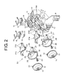
- reference numeral 1 designates a vehicle lighting system of the embodiment.
- the vehicle lighting system 1 is a vehicle headlamp such as a headlamp.
- the vehicle lighting system 1 is provided with: a heat sink member 2; a plurality of lamp units (two lamp units in the embodiment, namely one lamp unit 3S of focusing type and one lamp unit 3W of diffusion type); a lamp housing 4; and a lamp lens (such as a transparent outer lens, for example), although not shown.
- the two lamp units 3S, 3W are mounted on the heat sink member 2.
- the heat sink member 2 and the two lamp units 3S, 3W are disposed to be adjustable along an optical axis in a lamp room (not shown) which is partitioned by the lamp housing 4 and the lamp lens.
- the heat sink member 2 is made of a material with its high thermal conductivity, such as a resin or a metallic die cast (aluminum die cast in the embodiment).
- the heat sink member 2 also functions as a mount bracket.
- the heat sink member 2 is shaped stepwise when it is seen in a side view, and is formed in a shape such that a left side portion and a right side portion are displaced forward/backward when it is seen in a plan view.
- two placement portions 5 for placing semiconductor-type light sources; two mounting boss portions 6 for lamp unit mounting; a pivot portion 7 for optical axis adjustment (hereinafter, simply referred to as a "pivot portion”); an optical axis adjustment mechanism mounting portion 8 for vertical direction (hereinafter, simply referred to as a “vertical mount portion”); and an optical axis adjustment mechanism mounting portion 9 for horizontal direction (hereinafter, simply referred to as a "horizontal mounting portion”); a foreside heat radiation fin 10; a backside heat radiation fin 11, respectively.
- the two placement portions 5 are integrally provided at a horizontal part of a left-side and at a horizontal part of a right-side portion, of the heat sink member 2, respectively.
- the two mounting boss portions 6 are integrally provided at an inclined part of the right side portion and at an inclined portion of a left side portion, of the heat sink member 2, respectively.
- the pivot portion 7 is provided laterally integrally from an end face of the inclined part of the left side portion of the heat sink member 2.
- the vertical mount portion 8 is integrally provided at a lower end of a lower vertical part of the left side portion of the heat sink member 2.
- the horizontal mount portion 9 is integrally provided at an upper end of the lower vertical part of the right side portion of the heat sink member 2.
- the foreside heat radiation fin 10 is integrally provided in plurality on a foreface of a respective one of the upper vertical part, the inclined part, and the lower vertical part, of the heat sink member 2, in a vertical direction (longitudinal direction, upward-downward direction).
- the backside heat radiation fin 11 is integrally provided in plurality on a back face of a respective one of the upper vertical part, the inclined part, and the lower vertical part, of the heat sink member 2, in a vertical direction (longitudinal direction, upward-downward direction).
- the pivot portion 7 is positioned in proximity to a gravity in the forward/backward directions of the heat sink member 2 and the portions 5, 6, 7, 8, 9, 10, 11.
- the vertical mounting portion 8 and the horizontal mounting portion 9 are positioned in opposite to each other in the forward/backward directions while the pivot portion 7 is sandwiched therebetween.
- the pivot portion 7 is provided along a parting line PL (the double-dotted chain line of FIG. 4 ) of a die (not shown) for molding the heat sink member 2 and the portions 5, 6, 7, 8, 9, 10, 11.
- the foreside heat radiation fin 10 and the backside heat radiation fin 11 are integrally provided to be vertical (substantially vertical) to the parting line PL and in two directions, namely in the forward/backward directions.
- the parting line PL in the pivot portion 7, which is positioned at an upper part, and the parting line PL in the vertical mounting portion 8, which is positioned at a lower part, are interchangeable forward and backward.
- a center O1 of the pivot portion 7; a center 02 of the vertical mounting portion 8 (center of screw mounting of optical axis adjustment mechanism for vertical direction); and a center 03 of the horizontal mount portion 9 (center of screw mounting of optical axis adjustment mechanism for horizontal direction), are positioned in locations of three corners of a triangle, respectively, as seen in the plan view of FIG. 7 , as seen in the front view of FIG. 8 , and further, as seen in the side view of the FIG. 9 .
- An opening 12 for inserting a connector (not shown) therethrough is provided at an upper vertical portion which is adjacent to the placement portion 5 of the heat sink member 2.
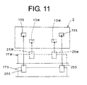
- recessed portions (or through holes) 13S, 13W serving as both of a guide portion, a temporary tacking portion, and a post-assembling proof portion are provided, respectively.
- the recessed portions 13S, 13 W are formed in a rectangular shape, as seen in a front view, and are provided in one pair.
- the two lamp units 3S, 3W are made up of: a semiconductor-type light source 14; a power feed holder 15; a mount spring 16; reflectors 17S, 17W; a shade 18; projecting lenses (convex lens, focusing lens) 19; and a mount screw 20.
- the semiconductor-type light source 14 for example, a self-luminous semiconductor-type light source such as an LED or an EL (organic EL) (an LED in the embodiment) is used.
- the semiconductor-type light source 14 is made of: a board 21 as a thermally conductive insulation board (ceramics, for example); a light emitter (not shown) of a very small, rectangle-shaped (square-shaped) LED chip provided on one face (top face) of the board 21; and an optical transmission member (lens) 22 which is substantially shaped like a hemisphere (dome-shaped), the member covering the light emitter.
- the other face (bottom face) of the board 21 of the semiconductor-type light source 14 is mounted on one face (top face) of the placement portion 5 of the heat sink member 2 in one direction (upward direction) by means of the power feed holder 15 and the mount spring 16.
- the power feed holder 15 is intended to feed power to the semiconductor-type light source 14 by electrically connecting a harness (not shown), which is connected to a power source (not shown), via a connector (not shown).
- the connector is inserted into the opening 12, and is electrically connected to the power feed holder 15, thereby enabling power feeding to the semiconductor-type light source 14.
- the mount spring 16 is fixed to the heat sink member 2, thereby mounting the power feed holder 15 and the semiconductor-type light source 14 on the heat sink member 2.
- the reflectors 17S, 17W are made up of an optically opaque resin member or the like.
- the reflectors 17S, 17W each are formed in a shape in which they open in two directions (forward direction and downward direction) and are closed in four directions (backward direction, upward direction, leftward direction, rightward direction).
- a reflecting surface 23S is provided for reflecting light (not shown) radiated from the light emitter of the semiconductor-type light source 14 in a predetermined direction in a predetermined focusing light distribution pattern (not shown).
- a reflecting surface (not shown) is provided for reflecting the light (not shown) radiated from the light emitter of the semiconductor-type light source 14 in a predetermined direction in a predetermined diffusive light distribution pattern (not shown).
- Mount groove portions 24 are provided at both of the left and right sides of the front portions of the reflectors 17S, 17W, respectively.
- protrusive portions 25S, 25W serving as a guide portion, a temporary tacking portion, and a post-assembling proof portion, are provided at both of the left and right sides at rear parts of the reflectors 17S, 17W, respectively.
- the protrusive portions 25S, 25W are provided in one pair and are formed in a laterally-viewed inverted-L shape protruding upward from the reflectors 17S, 17W, and protruding backward.
- a tip end of a respective one of the protrusive portions 25S, 25W is formed in a rectangular shape seen in a rear view.
- the widths of the two recessed portions 13S and the two protrusive portions 25S for the lamp unit 3S of focusing type, which are drawn in the solid line of FIG. 11 are greater than those of the two recessed portions 13 W and the two protrusive portions 25W for the lamp unit 3W of diffusion type, which are drawn in the dashed line of FIG. 11 .
- 11 are shown to be greater or smaller than actual widths of the two recessed portions 13W, 13W and the two protrusive portions 25S, 25W, in order to clarify the sizes of the widths of the two recessed portions 13S, 13W and the two protrusive portions 25S, 25W.
- the shade 18 is made up of an optically opaque resin member or the like.
- the shade 18 is made up of a front ring portion 26 and a rear shade portion 27 which are structured integrally with each other.
- Engagement groove portions 28 are provided at the top and bottom of the ring portions 26, respectively.
- Mount claw portions 29 are provided at both of the left and right sides of the shade portion 27, respectively.
- a through hole 30 for inserting the mount screw 20 therethrough is provided at a front part of the shade portion 27.
- the claw portion 29 of the shade 18 is mounted on the mount groove portion 24 of a respective one of the reflectors 17S, 17W.
- the protrusive portions 25S, 25W of the reflectors 17S, 17W, having the shade 18 integrally mounted thereon, are engaged with the recessed portions 13S, 13W of the heat sink member 2.
- a guide is provided for mounting of the reflectors 175, 17W that are integrated with each other and the shade 18 on the heat sink member 2; temporary tacking is provided for the reflectors 17S, 17W that are integrated with each other and the heat sink member 2 of the shade 18; and further, the reflectors 17S, 17W, which are integrated with each other, and the shade 18 are precluded from being incorrectly assembled with the heat sink member 2.
- the mount screw 20 is inserted into the through hole 30 of the shade 18 which is temporarily tacked with the heat sink member 2, and is then threaded into the mounting boss portion 6 of the heat sink member 2, whereby the reflectors 17S, 17W integrated with each other and the shade 18 are securely fixed to the heat sink member 2.
- the projecting lens 19 is a non-spherical convex lens.
- a foreside (external side) of the projecting lens 19 is formed in the shape of a non-spherical convex face with its great curvature (with its small radius of curvature)
- a backside (the side of the semiconductor-type light source 14) of the projecting lens 19 is formed in the shape of a non-spherical convex face with its small curvature (with its great radius of curvature).
- the backside of the projecting lens 19 may also be formed in the shape of a non-spherical flat face (plane).
- Engagement protrusive portions 31 are provided at the circumferential top and bottom of the projecting lens 19, respectively.
- the engagement protrusive portion 31 of the projecting lens 19 are engaged with the engagement groove portion 28 of the ring portion 26 of the shade 18 which is securely fixed to the heat sink member 2, whereby the projecting lens 19 is fixed to the shade 18 which is securely fixed to the heat sink member 2.
- the lamp unit 3S of focusing type and the lamp unit 3W of diffusion type are mounted on the heat sink member 2, respectively.
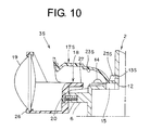
- the heat sink member 2 and the two lamp units 3S, 3W are disposed to be adjustable along an optical axis in a lamp room partitioned by the lamp housing 4 and the lamp lens, via: a pivot mechanism; and a pair of an optical axis adjustment mechanism for vertical direction (not shown) and an optical axis adjustment mechanism for horizontal direction (not shown).
- the pivot mechanism is made of: the pivot portion 7; a holder (mount bracket) 34 for rotatably mounting the pivot portion 7 on the lamp housing 4; and a screw 39.
- the pivot portion 7 is made up of: a shaft portion 32 shaped like a truncated cone, integrally protruding from the heat sink member 2; and a spherical portion 33 which is integrally provided at the shaft portion 32.
- the holder 34 is made up of: a hemispherical recessed portion 35; and a mount piece portion 36, integrally protruding from the hemispherical recessed portion 35 in two directions. Circular through holes 37 are provided at the two mount piece portions 36, respectively.
- the hemispherical recessed portions 35 of the two holders 34 are sandwiched between both sides relative to the spherical portion 33 of the pivot portion 7.
- the screw 39 is inserted into the through hole 37 of the two holders 34 and is threaded into a boss portion 38 of the lamp housing 4.
- the pivot portion 7 is thereby rotatably mounted on the lamp housing 4 via the holder 34.
- the optical axis adjustment mechanism for vertical direction and the optical axis adjustment mechanism for horizontal direction are made up of: an adjustment screw (not shown) which is mounted on the lamp housing 4 to enable rotation and disable advancement and retraction; and substantially spherical screw mounting, which is threaded into the adjustment screw and is rotatably mounted on a respective one of the vertical mount portion 8 and the horizontal mount portion 9 of the heat sink member 2.
- the screw mounting is screw-fed, and the heat sink member 2 and the two lamp units 3S, 3W are turned (rotated and/or inclined), respectively, in a horizontal direction around a vertical axis connecting a center O1 of the pivot portion 7 and a center 02 of the vertical mount portion 8 (the center of the screw mounting of the optical axis adjustment mechanism for vertical direction) with each other relative to the lamp housing 4 and in a vertical direction around a horizontal axis connecting the center O1 of the pivot portion 7 and a center 03 of the horizontal mount portion 9 (the center of the screw mounting of the optical axis adjustment mechanism for horizontal direction), and the optical axes of the two lamp units 3S, 3W are adjusted.
- the vehicle lighting system 1 of the embodiment is made of the constituent elements described above, and hereinafter, functions of the constituent elements will be described.
- the light emitters of semiconductor-type light sources 14 of a lamp unit 3S of focusing type and a lamp unit 3W of diffusion type is lit to emit light.
- the light radiated from the light emitter of the semiconductor-type light source 14 of the lamp unit 3 S of focusing type is reflected on a reflecting surface 23 S of a reflector 17S of focusing type in a predetermined direction in a predetermined focusing light distribution pattern, and the reflected light is illuminated to the outside.
- the light radiated from the light emitter of the semiconductor-type light source 14 of the lamp unit 3W of diffusion type is reflected on a reflecting surface of the reflector 17W of diffusion type in a predetermined direction in a predetermined diffusing light distribution pattern, and the reflected light is illuminated to the outside.
- the aforementioned heat is primarily radiated via: a mounting boss portion 6 and a shade 18, of a heat sink member 2; protrusive portions 25S, 25W engaging with recessed portions 13S, 13W and reflectors 17S, 17W, of the heat sink member 2; a pivot portion 7, a holder 34, a screw 39, and a lamp housing 4, of the heat sink member 2; a vertical mount portion 8, an optical axis adjustment mechanism for vertical direction, and a lamp housing 4, of the heat sink member 2; and a horizontal mount portion 9, an optical axis adjustment mechanism for horizontal direction, and the lamp housing 4, of the heat sink member 2.
- the vehicle lighting system 1 of the embodiment is made of the constituent elements and their associated functions as described above, and hereinafter, advantageous effect(s) thereof will be described.
- the vehicle lighting system 1 of the embodiment allows a heat radiation area to be increased by means of the pivot portion 7 for optical axis adjustment, the vertical mount portion (optical adjustment mechanism mounting portion for vertical direction) 8, and a horizontal mount portion (optical axis adjustment mechanism mounting portion for horizontal direction) 9, which are integrally provided on the heat sink member 2, so that a heat generated in the semiconductor-type light source 14 that is mounted on the heat sink member 2 can be efficiently radiated together with that of the heat sink member 2. In other words, heat radiation efficiency is improved.
- the vehicle lighting system 1 of the embodiment allows the pivot portion 7 for optical axis adjustment, to be mounted on the lamp housing 4 via a holder (pivot receptacle member) 34; and the optical axis adjustment mechanisms for vertical and horizontal directions, to be mounted, respectively, on the vertical mount portion (optical adjustment mechanism mounting portion for vertical direction) 8 and a horizontal mount portion (optical axis adjustment mechanism mounting portion for horizontal direction) 9 in a position relationship with the lamp housing 4.
- the optical axis of the semiconductor-type light source 14 can be thereby adjusted in the vertical and horizontal directions, via: the heat sink member 2; the pivot portion 7 for optical axis adjustment; the vertical mount portion (optical adjustment mechanism mounting portion for vertical direction) 8; and a horizontal mount portion (optical axis adjustment mechanism mounting portion for horizontal direction) 9, which are structured integrally with each other.
- the vehicle lighting system 1 of the embodiment allows the pivot portion 7 to be positioned in proximity to a gravity in the forward/backward directions of a respective one of the heat sink member 2 and the portions 5, 6, 7, 8, 9, 10, 11; and the vertical mount portion 8 and the horizontal mount portion 9 to be positioned to be opposite to each other in the forward/backward directions with the pivot portion 7 being sandwiched therebetween, thus improving durability relative to a vehicle vibration.
- the vehicle lighting system 1 of the embodiment allows the center O1 of the pivot portion 7; the center 02 of the vertical mount portion 8 (the center of the screw mounting of the optical axis adjustment mechanism for vertical direction; and the center 03 of the horizontal mount portion 9 (the center of the screw mounting of the optical axis adjustment mechanism for horizontal direction), to be positioned in three corners of a triangle, respectively, as seen in the plan view of FIG. 7 , as seen in the front view of FIG. 8 , and further, as seen in the side view of FIG. 9 , respectively. Therefore, the durability relative to a vehicle vibration is further improved.
- the vehicle lighting system 1 of the embodiment allows the pivot portion 7 to be provided along a parting line PL of a die (not shown) for molding the heat sink member 2 and the portions 5, 6, 7, 8, 9, 10, 11; and the foreside heat radiation fin 10 and the backside heat radiation fin 11 to be integrally provided at the heat sink member 2 to be vertical (substantially vertical) to the parting line PL and in two directions, namely in the forward and backward directions.
- the vehicle lighting system 1 of the embodiment becomes capable of die-mounting the heat sink member 2 having the pivot portion 7 for optical axis adjustment; and the foreside and backside heat radiation fins 10 and 11 in two directions relative to the pivot portion 7 for optical axis adjustment, are integrally provided therein.
- the vehicle lighting system 1 of the embodiment allows the pivot portion 7 for optical axis adjustment; and the foreside and backside heat radiation fins 10 and 11 in the two directions relative to the pivot portion 7 for optical axis adjustment, to be integrally provided at the heat sink member 2, thus further improving heat radiation efficiency.
- the vehicle lighting system 1 of the embodiment allows two lamp units 3S, 3W to be easily mounted on the heat sink member 2, since the recessed portions 13S, 13W and the protrusive portions 25S, 25W as guide portions provided at the heat sink member 2 and the two lamp units 3S, 3W serve as guides for mounting the two lamp units 3S, 3W.
- the vehicle lighting system 1 of the embodiment allows the two lamp units 3S, 3W to be reliably mounted on the heat sink member 2, since the recessed portions 13S, 13W and the protrusive portions 25S, 25W, as temporary tacking portions provided at the heat sink member 2 and the two lamp units 3S, 3W, serve as temporary tacking until the two lamp units 3S, 3W are securely fixed to the heat sink member 2.
- the vehicle lighting system 1 of the embodiment precludes the two lamp units 3 S, 3W from being incorrectly assembled to the heat sink member 2, since the recessed portions 13S, 13W and the protrusive portions 25S, 25W, as incorrect assembling proof portions provided at the heat sink member 2 and the two lamp units 3S, 3W, preclude the lamp units from being incorrectly assembled at the time of mounting the two lamp units 3S, 3 W on the heat sink member 2.
- the vehicle lighting system 1 of the embodiment allows the guide portion, the temporary tacking portion, and the post-assembling proof portion to be made of multifunctional recessed portions 13S, 13W and protrusive portions 25S, 25W, thus simplifying the relevant structure; and manufacturing cost can be reduced accordingly.
- the foregoing embodiment described a case in which the widths of the two recessed portions 13S and two protrusive portions 25S of the lamp unit 3S of focusing type are greater than those of the two recessed portions 13W and two protrusive portions 25W of the lamp unit 3W of diffusion type.
Landscapes
- Engineering & Computer Science (AREA)
- General Engineering & Computer Science (AREA)
- Physics & Mathematics (AREA)
- Microelectronics & Electronic Packaging (AREA)
- Optics & Photonics (AREA)
- Mechanical Engineering (AREA)
- Geometry (AREA)
- Non-Portable Lighting Devices Or Systems Thereof (AREA)
- Lighting Device Outwards From Vehicle And Optical Signal (AREA)
- Arrangement Of Elements, Cooling, Sealing, Or The Like Of Lighting Devices (AREA)
Applications Claiming Priority (1)
| Application Number | Priority Date | Filing Date | Title |
|---|---|---|---|
| JP2009031487A JP5287324B2 (ja) | 2009-02-13 | 2009-02-13 | 車両用灯具 |
Publications (2)
| Publication Number | Publication Date |
|---|---|
| EP2218964A2 true EP2218964A2 (de) | 2010-08-18 |
| EP2218964A3 EP2218964A3 (de) | 2015-07-22 |
Family
ID=41818640
Family Applications (1)
| Application Number | Title | Priority Date | Filing Date |
|---|---|---|---|
| EP10150848.9A Withdrawn EP2218964A3 (de) | 2009-02-13 | 2010-01-15 | Fahrzeugbeleuchtungssystem |
Country Status (4)
| Country | Link |
|---|---|
| US (1) | US8277099B2 (de) |
| EP (1) | EP2218964A3 (de) |
| JP (1) | JP5287324B2 (de) |
| CN (1) | CN101806419B (de) |
Cited By (9)
| Publication number | Priority date | Publication date | Assignee | Title |
|---|---|---|---|---|
| EP2213934A3 (de) * | 2009-02-03 | 2014-10-08 | Ichikoh Industries, Ltd. | Fahrzeugbeleuchtungsvorrichtung |
| AT514403A1 (de) * | 2013-05-29 | 2014-12-15 | Zizala Lichtsysteme Gmbh | Beleuchtungsvorrichtung für einen Fahrzeugscheinwerfer |
| FR3055265A1 (fr) * | 2016-09-01 | 2018-03-02 | Valeo Vision | Dispositif lumineux pour vehicule automobile |
| FR3062461A1 (fr) * | 2017-02-01 | 2018-08-03 | Valeo Vision | Module lumineux pivotable pour projecteur de vehicule |
| DE102017115593A1 (de) * | 2017-07-12 | 2019-01-17 | HELLA GmbH & Co. KGaA | Beleuchtungsvorrichtung für Fahrzeuge |
| EP3438523A1 (de) * | 2017-08-04 | 2019-02-06 | Valeo Vision | Schwenkbares leuchtmodul für fahrzeugscheinwerfer |
| WO2019141576A1 (de) * | 2018-01-16 | 2019-07-25 | Automotive Lighting Reutlingen Gmbh | Kraftfahrzeugscheinwerfer und einstellsystem für ein leuchtenbauteil des kraftfahrzeugscheinwerfers |
| US10414325B2 (en) | 2017-09-29 | 2019-09-17 | Varroc Lighting Systems, s.r.o. | Headlight for motor vehicles |
| EP2428725B1 (de) * | 2010-09-10 | 2019-11-20 | Koito Manufacturing Co., Ltd. | Fahrscheugscheinwerfer |
Families Citing this family (24)
| Publication number | Priority date | Publication date | Assignee | Title |
|---|---|---|---|---|
| JP5243505B2 (ja) * | 2010-09-13 | 2013-07-24 | 株式会社日本自動車部品総合研究所 | 車両用前照灯 |
| JP2012119285A (ja) * | 2010-12-03 | 2012-06-21 | Stanley Electric Co Ltd | 車両用灯具のレンズ取付構造 |
| JP5680947B2 (ja) * | 2010-12-03 | 2015-03-04 | スタンレー電気株式会社 | 車両用灯具のレンズホルダ取付構造 |
| JP5658016B2 (ja) * | 2010-12-03 | 2015-01-21 | スタンレー電気株式会社 | 車両用灯具 |
| US9518711B2 (en) | 2011-09-27 | 2016-12-13 | Truck-Lite Co., Llc | Modular headlamp assembly |
| US8840291B2 (en) * | 2011-10-26 | 2014-09-23 | Federal-Mogul Ignition Company | LED lamp assembly with heat sink |
| DE102012106314A1 (de) * | 2012-07-13 | 2014-01-16 | Hella Kgaa Hueck & Co. | Modulbaugruppe mit verschwenkbaren Halbleiterlichtmodulen für einenScheinwerfer |
| AT513915B1 (de) * | 2013-02-14 | 2015-11-15 | Zizala Lichtsysteme Gmbh | Lichtmodul sowie Beleuchtungsvorrichtung mit Lichtmodul für einen Fahrzeugscheinwerfer |
| DE102013104190A1 (de) * | 2013-04-25 | 2014-10-30 | Hella Kgaa Hueck & Co. | Modulbaugruppe zur Anordnung in einem Scheinwerfer |
| EP3048360B1 (de) * | 2013-08-23 | 2018-05-23 | Koito Manufacturing Co., Ltd. | Lampenvorrichtung für ein fahrzeug und beleuchtungsvorrichtung für ein fahrzeug |
| JP6577458B2 (ja) * | 2014-04-24 | 2019-09-18 | 株式会社小糸製作所 | 車両用照明装置 |
| JP2015215944A (ja) * | 2014-05-07 | 2015-12-03 | 市光工業株式会社 | 車両用灯具 |
| JP6319725B2 (ja) * | 2014-05-09 | 2018-05-09 | パナソニックIpマネジメント株式会社 | 照明装置及び照明装置を備える自動車 |
| CN105090852B (zh) * | 2014-05-09 | 2018-10-16 | 松下知识产权经营株式会社 | 照明装置及具备照明装置的汽车 |
| US9587794B2 (en) * | 2014-05-21 | 2017-03-07 | Ford Global Technologies, Llc | Headlamp assembly with multiple high aspect ratio lenses |
| FR3022868B1 (fr) * | 2014-06-30 | 2018-01-12 | Valeo Vision | Montage pivotant d'un module d'eclairage pour vehicule autombile |
| DE102015202544B4 (de) * | 2015-02-12 | 2021-02-04 | Automotive Lighting Reutlingen Gmbh | Kraftfahrzeugleuchte mit einem das Licht brechenden Element, welches die Form einer beschnittenen Halbkugel aufweist und dessen beschnittene Grenzflächen totalreflektierend sind |
| AT517752B1 (de) * | 2015-09-17 | 2018-04-15 | Zkw Group Gmbh | Lichtmodul für einen kraftfahrzeugscheinwerfer zur abstrahlung einer langreichweitigen lichtverteilung sowie beleuchtungsvorrichtung |
| CN105135320B (zh) * | 2015-09-28 | 2017-10-20 | 台州探陆泽汽配有限公司 | 一种汽车大灯 |
| FR3053941B1 (fr) * | 2016-07-13 | 2018-07-20 | Peugeot Citroen Automobiles Sa | Dispositif de reparation a paroi de masquage, pour un bloc optique usage de vehicule |
| JP6765241B2 (ja) * | 2016-07-13 | 2020-10-07 | 株式会社小糸製作所 | 車輌用照明装置 |
| JP2019102230A (ja) * | 2017-11-30 | 2019-06-24 | 株式会社小糸製作所 | 車両用灯具 |
| CN114667236B (zh) * | 2019-11-20 | 2023-04-07 | 三菱电机株式会社 | 前照灯装置 |
| EP3941168A1 (de) * | 2020-07-14 | 2022-01-19 | ZKW Group GmbH | Fahrzeugmodul mit einer manipulationserkennenden elektronischen steuereinheit |
Citations (1)
| Publication number | Priority date | Publication date | Assignee | Title |
|---|---|---|---|---|
| JP2004311224A (ja) | 2003-04-08 | 2004-11-04 | Koito Mfg Co Ltd | 車両用前照灯 |
Family Cites Families (16)
| Publication number | Priority date | Publication date | Assignee | Title |
|---|---|---|---|---|
| US4318162A (en) * | 1979-10-16 | 1982-03-02 | General Electric Company | Snap in coupling assembly for a vehicle headlamp |
| US4318161A (en) * | 1979-10-16 | 1982-03-02 | General Electric Company | Snap in coupling assembly for a vehicle headlamp having a trim rim integral therewith |
| JPH0423709Y2 (de) * | 1987-02-26 | 1992-06-03 | ||
| JP3128616B2 (ja) * | 1996-07-02 | 2001-01-29 | 株式会社小糸製作所 | 車輌用灯具の光軸調整装置 |
| JP2000085457A (ja) * | 1998-09-18 | 2000-03-28 | Koito Mfg Co Ltd | 車両用灯具 |
| JP2002304905A (ja) * | 2001-04-04 | 2002-10-18 | Ichikoh Ind Ltd | 車両用灯具 |
| US7008135B2 (en) * | 2002-01-31 | 2006-03-07 | Guide Corporation | Stamped ball socket |
| JP4264335B2 (ja) * | 2003-12-05 | 2009-05-13 | 株式会社小糸製作所 | 車両用前照灯 |
| JP4640967B2 (ja) * | 2005-08-12 | 2011-03-02 | 株式会社小糸製作所 | 車両用前照灯 |
| JP4595781B2 (ja) * | 2005-10-17 | 2010-12-08 | 市光工業株式会社 | 車両用灯具 |
| JP4694427B2 (ja) * | 2006-07-05 | 2011-06-08 | 株式会社小糸製作所 | 車両用前照灯 |
| JP4666312B2 (ja) * | 2006-09-08 | 2011-04-06 | スタンレー電気株式会社 | 車両用灯具 |
| JP4992111B2 (ja) * | 2007-09-20 | 2012-08-08 | 株式会社小糸製作所 | 車両用灯具 |
| KR20090063573A (ko) * | 2007-12-14 | 2009-06-18 | 현대자동차주식회사 | 발광 다이오드 헤드램프 에이밍 장치 |
| KR100989390B1 (ko) * | 2008-02-15 | 2010-10-25 | 에스엘 주식회사 | 차량용 헤드 램프 구조 |
| CN101307873A (zh) * | 2008-06-27 | 2008-11-19 | 中海阳(北京)能源科技有限公司 | Led投光灯 |
-
2009
- 2009-02-13 JP JP2009031487A patent/JP5287324B2/ja active Active
- 2009-10-30 CN CN2009102070972A patent/CN101806419B/zh not_active Expired - Fee Related
-
2010
- 2010-01-15 EP EP10150848.9A patent/EP2218964A3/de not_active Withdrawn
- 2010-01-19 US US12/689,779 patent/US8277099B2/en active Active
Patent Citations (1)
| Publication number | Priority date | Publication date | Assignee | Title |
|---|---|---|---|---|
| JP2004311224A (ja) | 2003-04-08 | 2004-11-04 | Koito Mfg Co Ltd | 車両用前照灯 |
Cited By (12)
| Publication number | Priority date | Publication date | Assignee | Title |
|---|---|---|---|---|
| EP2213934A3 (de) * | 2009-02-03 | 2014-10-08 | Ichikoh Industries, Ltd. | Fahrzeugbeleuchtungsvorrichtung |
| EP2428725B1 (de) * | 2010-09-10 | 2019-11-20 | Koito Manufacturing Co., Ltd. | Fahrscheugscheinwerfer |
| AT514403A1 (de) * | 2013-05-29 | 2014-12-15 | Zizala Lichtsysteme Gmbh | Beleuchtungsvorrichtung für einen Fahrzeugscheinwerfer |
| AT514403B1 (de) * | 2013-05-29 | 2015-06-15 | Zizala Lichtsysteme Gmbh | Beleuchtungsvorrichtung für einen Fahrzeugscheinwerfer sowie Fahrzeugscheinwerfer |
| FR3055265A1 (fr) * | 2016-09-01 | 2018-03-02 | Valeo Vision | Dispositif lumineux pour vehicule automobile |
| FR3062461A1 (fr) * | 2017-02-01 | 2018-08-03 | Valeo Vision | Module lumineux pivotable pour projecteur de vehicule |
| US11001193B2 (en) | 2017-02-01 | 2021-05-11 | Valeo Vision | Pivotable lighting module for vehicle lamp |
| DE102017115593A1 (de) * | 2017-07-12 | 2019-01-17 | HELLA GmbH & Co. KGaA | Beleuchtungsvorrichtung für Fahrzeuge |
| EP3438523A1 (de) * | 2017-08-04 | 2019-02-06 | Valeo Vision | Schwenkbares leuchtmodul für fahrzeugscheinwerfer |
| US10414325B2 (en) | 2017-09-29 | 2019-09-17 | Varroc Lighting Systems, s.r.o. | Headlight for motor vehicles |
| CZ308796B6 (cs) * | 2017-09-29 | 2021-05-26 | Varroc Lighting Systems, s.r.o. | Světlomet motorových vozidel |
| WO2019141576A1 (de) * | 2018-01-16 | 2019-07-25 | Automotive Lighting Reutlingen Gmbh | Kraftfahrzeugscheinwerfer und einstellsystem für ein leuchtenbauteil des kraftfahrzeugscheinwerfers |
Also Published As
| Publication number | Publication date |
|---|---|
| JP5287324B2 (ja) | 2013-09-11 |
| JP2010186698A (ja) | 2010-08-26 |
| CN101806419B (zh) | 2012-11-07 |
| CN101806419A (zh) | 2010-08-18 |
| US8277099B2 (en) | 2012-10-02 |
| US20100208483A1 (en) | 2010-08-19 |
| EP2218964A3 (de) | 2015-07-22 |
Similar Documents
| Publication | Publication Date | Title |
|---|---|---|
| US8277099B2 (en) | Vehicle lighting system | |
| US10309606B2 (en) | Vehicle lamp | |
| US8287167B2 (en) | Lamp unit | |
| US7972049B2 (en) | Vehicle lighting device | |
| US7481561B2 (en) | Vehicle lighting device | |
| US7972046B2 (en) | Vehicle lighting device | |
| US7794128B2 (en) | Lamp unit of vehicle headlamp | |
| EP2522898B1 (de) | Fahrzeugleuchte | |
| CN1523260A (zh) | 车辆用前照灯 | |
| CN102192458A (zh) | 车辆用灯具 | |
| JP5332688B2 (ja) | 車両用灯具 | |
| KR101533709B1 (ko) | 차량용 led 램프 모듈 | |
| US20130341670A1 (en) | Light source module | |
| US7607806B2 (en) | Vehicle lamp | |
| KR20120107894A (ko) | 발광 모듈 및 등기구 | |
| JP4595781B2 (ja) | 車両用灯具 | |
| JPWO2017179465A1 (ja) | 発光ユニットおよび車両用灯具 | |
| JP5040899B2 (ja) | 車両用灯具 | |
| JP6252110B2 (ja) | 車両用灯具 | |
| US20160215945A1 (en) | Vehicular lighting | |
| CN108431490A (zh) | 具有准确光学元件定位的照明布置 | |
| JP2014049249A (ja) | 灯具ユニット |
Legal Events
| Date | Code | Title | Description |
|---|---|---|---|
| PUAI | Public reference made under article 153(3) epc to a published international application that has entered the european phase |
Free format text: ORIGINAL CODE: 0009012 |
|
| AK | Designated contracting states |
Kind code of ref document: A2 Designated state(s): AT BE BG CH CY CZ DE DK EE ES FI FR GB GR HR HU IE IS IT LI LT LU LV MC MK MT NL NO PL PT RO SE SI SK SM TR |
|
| AX | Request for extension of the european patent |
Extension state: AL BA RS |
|
| PUAL | Search report despatched |
Free format text: ORIGINAL CODE: 0009013 |
|
| AK | Designated contracting states |
Kind code of ref document: A3 Designated state(s): AT BE BG CH CY CZ DE DK EE ES FI FR GB GR HR HU IE IS IT LI LT LU LV MC MK MT NL NO PL PT RO SE SI SK SM TR |
|
| AX | Request for extension of the european patent |
Extension state: AL BA RS |
|
| RIC1 | Information provided on ipc code assigned before grant |
Ipc: F21S 8/10 20060101AFI20150618BHEP Ipc: B60Q 1/068 20060101ALI20150618BHEP Ipc: F21V 21/14 20060101ALI20150618BHEP Ipc: F21V 29/00 20150101ALI20150618BHEP |
|
| 17P | Request for examination filed |
Effective date: 20160122 |
|
| RBV | Designated contracting states (corrected) |
Designated state(s): AT BE BG CH CY CZ DE DK EE ES FI FR GB GR HR HU IE IS IT LI LT LU LV MC MK MT NL NO PL PT RO SE SI SK SM TR |
|
| 17Q | First examination report despatched |
Effective date: 20180430 |
|
| RIC1 | Information provided on ipc code assigned before grant |
Ipc: B60Q 1/068 20060101AFI20181212BHEP Ipc: F21S 45/47 20180101ALI20181212BHEP Ipc: F21S 41/147 20180101ALI20181212BHEP |
|
| RAP1 | Party data changed (applicant data changed or rights of an application transferred) |
Owner name: ICHIKOH INDUSTRIES, LTD. |
|
| STAA | Information on the status of an ep patent application or granted ep patent |
Free format text: STATUS: THE APPLICATION IS DEEMED TO BE WITHDRAWN |
|
| 18D | Application deemed to be withdrawn |
Effective date: 20200218 |