EP2204231A1 - Keramikpartikel - Google Patents
Keramikpartikel Download PDFInfo
- Publication number
- EP2204231A1 EP2204231A1 EP10003178A EP10003178A EP2204231A1 EP 2204231 A1 EP2204231 A1 EP 2204231A1 EP 10003178 A EP10003178 A EP 10003178A EP 10003178 A EP10003178 A EP 10003178A EP 2204231 A1 EP2204231 A1 EP 2204231A1
- Authority
- EP
- European Patent Office
- Prior art keywords
- particles
- urea
- solidification liquid
- mass
- flow
- Prior art date
- Legal status (The legal status is an assumption and is not a legal conclusion. Google has not performed a legal analysis and makes no representation as to the accuracy of the status listed.)
- Withdrawn
Links
Images


Classifications
-
- B—PERFORMING OPERATIONS; TRANSPORTING
- B01—PHYSICAL OR CHEMICAL PROCESSES OR APPARATUS IN GENERAL
- B01J—CHEMICAL OR PHYSICAL PROCESSES, e.g. CATALYSIS OR COLLOID CHEMISTRY; THEIR RELEVANT APPARATUS
- B01J2/00—Processes or devices for granulating materials, e.g. fertilisers in general; Rendering particulate materials free flowing in general, e.g. making them hydrophobic
- B01J2/18—Processes or devices for granulating materials, e.g. fertilisers in general; Rendering particulate materials free flowing in general, e.g. making them hydrophobic using a vibrating apparatus
-
- B—PERFORMING OPERATIONS; TRANSPORTING
- B01—PHYSICAL OR CHEMICAL PROCESSES OR APPARATUS IN GENERAL
- B01D—SEPARATION
- B01D53/00—Separation of gases or vapours; Recovering vapours of volatile solvents from gases; Chemical or biological purification of waste gases, e.g. engine exhaust gases, smoke, fumes, flue gases, aerosols
- B01D53/34—Chemical or biological purification of waste gases
- B01D53/74—General processes for purification of waste gases; Apparatus or devices specially adapted therefor
- B01D53/86—Catalytic processes
- B01D53/90—Injecting reactants
-
- B—PERFORMING OPERATIONS; TRANSPORTING
- B01—PHYSICAL OR CHEMICAL PROCESSES OR APPARATUS IN GENERAL
- B01D—SEPARATION
- B01D53/00—Separation of gases or vapours; Recovering vapours of volatile solvents from gases; Chemical or biological purification of waste gases, e.g. engine exhaust gases, smoke, fumes, flue gases, aerosols
- B01D53/34—Chemical or biological purification of waste gases
- B01D53/92—Chemical or biological purification of waste gases of engine exhaust gases
- B01D53/94—Chemical or biological purification of waste gases of engine exhaust gases by catalytic processes
- B01D53/9404—Removing only nitrogen compounds
- B01D53/9409—Nitrogen oxides
-
- B—PERFORMING OPERATIONS; TRANSPORTING
- B01—PHYSICAL OR CHEMICAL PROCESSES OR APPARATUS IN GENERAL
- B01J—CHEMICAL OR PHYSICAL PROCESSES, e.g. CATALYSIS OR COLLOID CHEMISTRY; THEIR RELEVANT APPARATUS
- B01J2/00—Processes or devices for granulating materials, e.g. fertilisers in general; Rendering particulate materials free flowing in general, e.g. making them hydrophobic
- B01J2/02—Processes or devices for granulating materials, e.g. fertilisers in general; Rendering particulate materials free flowing in general, e.g. making them hydrophobic by dividing the liquid material into drops, e.g. by spraying, and solidifying the drops
- B01J2/06—Processes or devices for granulating materials, e.g. fertilisers in general; Rendering particulate materials free flowing in general, e.g. making them hydrophobic by dividing the liquid material into drops, e.g. by spraying, and solidifying the drops in a liquid medium
-
- B—PERFORMING OPERATIONS; TRANSPORTING
- B29—WORKING OF PLASTICS; WORKING OF SUBSTANCES IN A PLASTIC STATE IN GENERAL
- B29B—PREPARATION OR PRETREATMENT OF THE MATERIAL TO BE SHAPED; MAKING GRANULES OR PREFORMS; RECOVERY OF PLASTICS OR OTHER CONSTITUENTS OF WASTE MATERIAL CONTAINING PLASTICS
- B29B9/00—Making granules
- B29B9/10—Making granules by moulding the material, i.e. treating it in the molten state
-
- C—CHEMISTRY; METALLURGY
- C04—CEMENTS; CONCRETE; ARTIFICIAL STONE; CERAMICS; REFRACTORIES
- C04B—LIME, MAGNESIA; SLAG; CEMENTS; COMPOSITIONS THEREOF, e.g. MORTARS, CONCRETE OR LIKE BUILDING MATERIALS; ARTIFICIAL STONE; CERAMICS; REFRACTORIES; TREATMENT OF NATURAL STONE
- C04B35/00—Shaped ceramic products characterised by their composition; Ceramics compositions; Processing powders of inorganic compounds preparatory to the manufacturing of ceramic products
- C04B35/01—Shaped ceramic products characterised by their composition; Ceramics compositions; Processing powders of inorganic compounds preparatory to the manufacturing of ceramic products based on oxide ceramics
- C04B35/48—Shaped ceramic products characterised by their composition; Ceramics compositions; Processing powders of inorganic compounds preparatory to the manufacturing of ceramic products based on oxide ceramics based on zirconium or hafnium oxides, zirconates, zircon or hafnates
- C04B35/486—Fine ceramics
-
- C—CHEMISTRY; METALLURGY
- C04—CEMENTS; CONCRETE; ARTIFICIAL STONE; CERAMICS; REFRACTORIES
- C04B—LIME, MAGNESIA; SLAG; CEMENTS; COMPOSITIONS THEREOF, e.g. MORTARS, CONCRETE OR LIKE BUILDING MATERIALS; ARTIFICIAL STONE; CERAMICS; REFRACTORIES; TREATMENT OF NATURAL STONE
- C04B35/00—Shaped ceramic products characterised by their composition; Ceramics compositions; Processing powders of inorganic compounds preparatory to the manufacturing of ceramic products
- C04B35/622—Forming processes; Processing powders of inorganic compounds preparatory to the manufacturing of ceramic products
- C04B35/626—Preparing or treating the powders individually or as batches ; preparing or treating macroscopic reinforcing agents for ceramic products, e.g. fibres; mechanical aspects section B
- C04B35/62605—Treating the starting powders individually or as mixtures
- C04B35/62625—Wet mixtures
- C04B35/6263—Wet mixtures characterised by their solids loadings, i.e. the percentage of solids
-
- C—CHEMISTRY; METALLURGY
- C07—ORGANIC CHEMISTRY
- C07C—ACYCLIC OR CARBOCYCLIC COMPOUNDS
- C07C273/00—Preparation of urea or its derivatives, i.e. compounds containing any of the groups, the nitrogen atoms not being part of nitro or nitroso groups
- C07C273/02—Preparation of urea or its derivatives, i.e. compounds containing any of the groups, the nitrogen atoms not being part of nitro or nitroso groups of urea, its salts, complexes or addition compounds
- C07C273/14—Separation; Purification; Stabilisation; Use of additives
-
- B—PERFORMING OPERATIONS; TRANSPORTING
- B01—PHYSICAL OR CHEMICAL PROCESSES OR APPARATUS IN GENERAL
- B01D—SEPARATION
- B01D2251/00—Reactants
- B01D2251/20—Reductants
- B01D2251/206—Ammonium compounds
- B01D2251/2067—Urea
-
- B—PERFORMING OPERATIONS; TRANSPORTING
- B01—PHYSICAL OR CHEMICAL PROCESSES OR APPARATUS IN GENERAL
- B01D—SEPARATION
- B01D2258/00—Sources of waste gases
- B01D2258/01—Engine exhaust gases
-
- C—CHEMISTRY; METALLURGY
- C04—CEMENTS; CONCRETE; ARTIFICIAL STONE; CERAMICS; REFRACTORIES
- C04B—LIME, MAGNESIA; SLAG; CEMENTS; COMPOSITIONS THEREOF, e.g. MORTARS, CONCRETE OR LIKE BUILDING MATERIALS; ARTIFICIAL STONE; CERAMICS; REFRACTORIES; TREATMENT OF NATURAL STONE
- C04B2235/00—Aspects relating to ceramic starting mixtures or sintered ceramic products
- C04B2235/02—Composition of constituents of the starting material or of secondary phases of the final product
- C04B2235/30—Constituents and secondary phases not being of a fibrous nature
- C04B2235/32—Metal oxides, mixed metal oxides, or oxide-forming salts thereof, e.g. carbonates, nitrates, (oxy)hydroxides, chlorides
- C04B2235/3224—Rare earth oxide or oxide forming salts thereof, e.g. scandium oxide
- C04B2235/3229—Cerium oxides or oxide-forming salts thereof
-
- C—CHEMISTRY; METALLURGY
- C04—CEMENTS; CONCRETE; ARTIFICIAL STONE; CERAMICS; REFRACTORIES
- C04B—LIME, MAGNESIA; SLAG; CEMENTS; COMPOSITIONS THEREOF, e.g. MORTARS, CONCRETE OR LIKE BUILDING MATERIALS; ARTIFICIAL STONE; CERAMICS; REFRACTORIES; TREATMENT OF NATURAL STONE
- C04B2235/00—Aspects relating to ceramic starting mixtures or sintered ceramic products
- C04B2235/02—Composition of constituents of the starting material or of secondary phases of the final product
- C04B2235/30—Constituents and secondary phases not being of a fibrous nature
- C04B2235/32—Metal oxides, mixed metal oxides, or oxide-forming salts thereof, e.g. carbonates, nitrates, (oxy)hydroxides, chlorides
- C04B2235/3231—Refractory metal oxides, their mixed metal oxides, or oxide-forming salts thereof
- C04B2235/3244—Zirconium oxides, zirconates, hafnium oxides, hafnates, or oxide-forming salts thereof
- C04B2235/3246—Stabilised zirconias, e.g. YSZ or cerium stabilised zirconia
-
- C—CHEMISTRY; METALLURGY
- C04—CEMENTS; CONCRETE; ARTIFICIAL STONE; CERAMICS; REFRACTORIES
- C04B—LIME, MAGNESIA; SLAG; CEMENTS; COMPOSITIONS THEREOF, e.g. MORTARS, CONCRETE OR LIKE BUILDING MATERIALS; ARTIFICIAL STONE; CERAMICS; REFRACTORIES; TREATMENT OF NATURAL STONE
- C04B2235/00—Aspects relating to ceramic starting mixtures or sintered ceramic products
- C04B2235/02—Composition of constituents of the starting material or of secondary phases of the final product
- C04B2235/50—Constituents or additives of the starting mixture chosen for their shape or used because of their shape or their physical appearance
- C04B2235/52—Constituents or additives characterised by their shapes
- C04B2235/528—Spheres
-
- C—CHEMISTRY; METALLURGY
- C04—CEMENTS; CONCRETE; ARTIFICIAL STONE; CERAMICS; REFRACTORIES
- C04B—LIME, MAGNESIA; SLAG; CEMENTS; COMPOSITIONS THEREOF, e.g. MORTARS, CONCRETE OR LIKE BUILDING MATERIALS; ARTIFICIAL STONE; CERAMICS; REFRACTORIES; TREATMENT OF NATURAL STONE
- C04B2235/00—Aspects relating to ceramic starting mixtures or sintered ceramic products
- C04B2235/02—Composition of constituents of the starting material or of secondary phases of the final product
- C04B2235/50—Constituents or additives of the starting mixture chosen for their shape or used because of their shape or their physical appearance
- C04B2235/52—Constituents or additives characterised by their shapes
- C04B2235/5296—Constituents or additives characterised by their shapes with a defined aspect ratio, e.g. indicating sphericity
-
- C—CHEMISTRY; METALLURGY
- C04—CEMENTS; CONCRETE; ARTIFICIAL STONE; CERAMICS; REFRACTORIES
- C04B—LIME, MAGNESIA; SLAG; CEMENTS; COMPOSITIONS THEREOF, e.g. MORTARS, CONCRETE OR LIKE BUILDING MATERIALS; ARTIFICIAL STONE; CERAMICS; REFRACTORIES; TREATMENT OF NATURAL STONE
- C04B2235/00—Aspects relating to ceramic starting mixtures or sintered ceramic products
- C04B2235/02—Composition of constituents of the starting material or of secondary phases of the final product
- C04B2235/50—Constituents or additives of the starting mixture chosen for their shape or used because of their shape or their physical appearance
- C04B2235/54—Particle size related information
- C04B2235/5418—Particle size related information expressed by the size of the particles or aggregates thereof
- C04B2235/5427—Particle size related information expressed by the size of the particles or aggregates thereof millimeter or submillimeter sized, i.e. larger than 0,1 mm
-
- C—CHEMISTRY; METALLURGY
- C04—CEMENTS; CONCRETE; ARTIFICIAL STONE; CERAMICS; REFRACTORIES
- C04B—LIME, MAGNESIA; SLAG; CEMENTS; COMPOSITIONS THEREOF, e.g. MORTARS, CONCRETE OR LIKE BUILDING MATERIALS; ARTIFICIAL STONE; CERAMICS; REFRACTORIES; TREATMENT OF NATURAL STONE
- C04B2235/00—Aspects relating to ceramic starting mixtures or sintered ceramic products
- C04B2235/70—Aspects relating to sintered or melt-casted ceramic products
- C04B2235/74—Physical characteristics
- C04B2235/77—Density
-
- F—MECHANICAL ENGINEERING; LIGHTING; HEATING; WEAPONS; BLASTING
- F01—MACHINES OR ENGINES IN GENERAL; ENGINE PLANTS IN GENERAL; STEAM ENGINES
- F01N—GAS-FLOW SILENCERS OR EXHAUST APPARATUS FOR MACHINES OR ENGINES IN GENERAL; GAS-FLOW SILENCERS OR EXHAUST APPARATUS FOR INTERNAL-COMBUSTION ENGINES
- F01N2610/00—Adding substances to exhaust gases
- F01N2610/02—Adding substances to exhaust gases the substance being ammonia or urea
-
- F—MECHANICAL ENGINEERING; LIGHTING; HEATING; WEAPONS; BLASTING
- F01—MACHINES OR ENGINES IN GENERAL; ENGINE PLANTS IN GENERAL; STEAM ENGINES
- F01N—GAS-FLOW SILENCERS OR EXHAUST APPARATUS FOR MACHINES OR ENGINES IN GENERAL; GAS-FLOW SILENCERS OR EXHAUST APPARATUS FOR INTERNAL-COMBUSTION ENGINES
- F01N2610/00—Adding substances to exhaust gases
- F01N2610/11—Adding substances to exhaust gases the substance or part of the dosing system being cooled
-
- F—MECHANICAL ENGINEERING; LIGHTING; HEATING; WEAPONS; BLASTING
- F01—MACHINES OR ENGINES IN GENERAL; ENGINE PLANTS IN GENERAL; STEAM ENGINES
- F01N—GAS-FLOW SILENCERS OR EXHAUST APPARATUS FOR MACHINES OR ENGINES IN GENERAL; GAS-FLOW SILENCERS OR EXHAUST APPARATUS FOR INTERNAL-COMBUSTION ENGINES
- F01N2610/00—Adding substances to exhaust gases
- F01N2610/12—Adding substances to exhaust gases the substance being in solid form, e.g. pellets or powder
-
- Y—GENERAL TAGGING OF NEW TECHNOLOGICAL DEVELOPMENTS; GENERAL TAGGING OF CROSS-SECTIONAL TECHNOLOGIES SPANNING OVER SEVERAL SECTIONS OF THE IPC; TECHNICAL SUBJECTS COVERED BY FORMER USPC CROSS-REFERENCE ART COLLECTIONS [XRACs] AND DIGESTS
- Y10—TECHNICAL SUBJECTS COVERED BY FORMER USPC
- Y10T—TECHNICAL SUBJECTS COVERED BY FORMER US CLASSIFICATION
- Y10T428/00—Stock material or miscellaneous articles
- Y10T428/29—Coated or structually defined flake, particle, cell, strand, strand portion, rod, filament, macroscopic fiber or mass thereof
- Y10T428/2982—Particulate matter [e.g., sphere, flake, etc.]
- Y10T428/2991—Coated
Definitions
- the present invention relates to a method and an apparatus for producing solid particles from a flowable starting material, wherein the flowable starting material is dropletized and the droplets are introduced along a movement path into a solidification liquid, in which they are solidified to form the solid particles.
- the invention further relates to solid particles with high sphericity, in particular urea particles and particles of a ceramic material.
- a method of the type mentioned is from the US 4,436,782 known. This document relates to the granulation of an oligomeric polyethylene terephthalate into pellets.
- Sputtering and spraying methods are the dominant methods of producing spherical microparticles today. In all these methods, a particle collective is obtained with a disadvantageously very broad diameter, mass and density distribution. Moreover, the particles produced usually show a low roundness or sphericity. In addition, only very small particles on the one hand and on the other hand in their shape and size only very different particles can be produced by the spraying and in particular the atomization by these methods.
- spherical particles are granulation methods.
- ceramic oxides are mixed with a ceramic binder and in classical granulation processes, for example by means of built-up granulators to round particles deformed (eg EP 26 918 . EP 1136464 A2 ). Larger particles of approx. 3-10 mm are produced by pressing in rubber matrices.
- Spherical particles of stabilized zirconium oxides with a CeO 2 content of less than 30% by mass have recently been used as grinding media and because of their excellent material properties serve as economically interesting alternative materials to known stabilized zirconium oxides of CaO, MgO or Y 2 O 3 .
- a narrow diameter, mass and density distribution is technically advantageous.
- a known method for producing spherical microparticles as grinding media are, for example, dripping methods.
- an aqueous suspension of the oxides which has been mixed with a ceramic binder, is dripped dropwise through a nozzle into a chemically hardening solution for the production of magnesium-stabilized zirconium oxides as grinding media in the shaping step.
- EP 0 677 325 A1 describes the dripping of an aqueous suspension of the oxides ZrO 2 and Mg (OH) 2 with a ceramic binder into a chemically curing ion exchange solution.
- a process for the oxidation of actinoxides is described.
- Particulate ureas and urea compounds are also widely known in the art. They are mainly used in the agricultural industry, where they are used as fertilizer. (z, B, JP 2002114592 . US 3,941,578 . JP 8067591 ).
- urea particles differ fundamentally. So urea particles are known which have diameters in the micron range, such as in the US 4,469,648 described. Usually, however, the particle diameter in the mm range as in the EP 1 288 179 described. Even larger urea granules are, for example, according to the CN 1237053 known.
- urea particles are usually produced in large quantities by means of prilling or granulation processes in which a highly concentrated urea solution or a urea melt is cooled by contact with a gas, such as cold air, thereby solidifying into particles.
- Characteristic of these particles produced by these methods is the generation of a particle collective with disadvantageously very broad diameter and mass distributions.
- the particles produced also show corresponding deviations in their geometry, that is, the particles have a broad particle size distribution and no sufficient roundness or sphericity for certain applications.
- a solidification liquid is selected.
- the flowable starting material contains ceramic particles
- the surface tension of the solidification liquid is smaller than that of the starting material, this means ⁇ solidification liquid ⁇ drop , flowable starting material .
- a surface tension of the solidification liquid of less than 50 mN / m, in particular of less than 30 mN / m ensures a transition of the drops of the flowable starting material in the solidification liquid, are avoided in the damage or even destruction of the drops in the phase transition.
- Interfacial tensions between 25 and 50 mN / m are advantageous, in particular between 30 mN / m, especially between 35 and 50 mN / m.
- flowable starting material is especially a melt, in particular a urea-containing melt or a polymer melt or a thermally unstable melt and as solidification liquid, a coolant, in particular a fluid, both a lower surface tension than the flowable starting material and an opposite polarity in comparison having the flowable starting material.
- a coolant in particular a fluid, both a lower surface tension than the flowable starting material and an opposite polarity in comparison having the flowable starting material.
- this is preferably a nonpolar fluid.
- a fluid is understood to mean a flowable substance or a substance mixture, in particular a liquid or a liquid mixture.
- a flowable suspension containing a ceramic material and a binder and which for solidification in a flowing or non-flowing, in particular in non-flowing into a stationary solidification liquid in the a chemical cure is caused is introduced.
- a correspondingly high polarity difference characterized by a correspondingly high interfacial tension between the drops of the flowable starting material and the solidification liquid in combination with a deliberately set solidification of the droplets of the flowable starting material to the solid particles advantageous.
- the interfacial tension value is high, there is a large polarity difference between the two medium phases.
- the surface and / or interfacial tensions are temperature-dependent and are therefore in a temperature of 20 ° C or when melting to a characteristic transformation temperature (eg melting temperature, glass transition point) by definition.
- the polarity difference between the suspension and the solidification liquid can be used to advantage, in particular if the solidification liquid consists of two little or immiscible phases or polarities and / or different densities that in particular the non-polar, less dense and surface-lower phase compared to the flowable starting material forms the still flowable particles into a spherical particle or reformed, and subsequently in the denser phase, the chemical curing is effected.
- a solidification liquid is furthermore particularly advantageous in the case of the pulverization of a flowable starting material based on a ceramic material and a binder, which consists of at least two miscible components of different polarity, wherein the less polar component utilizes the opposite interaction to form a spherical particle, and by lowering the reaction rate through the less polar component, the chemical cure time can be increased such that the spherical particle reforming particle is flowable for a sufficient amount of time remains and is suitably chemically hardened.
- a solidification liquid consisting of two immiscible phases or polarities and / or different densities, in particular the nonpolar, less dense and surface-lower phase
- the flowable starting material forms the particles into a spherical particle or reformed, since this is still sufficiently flowable, and in the denser phase, the chemical curing by the addition of a miscible but less polar component, the chemical curing can be controlled in time.
- an interfacial tension between the drops of the flowable starting material and the solidification liquid is set between 25 to 50 mN / m, in particular between 30 and 50 mN / m and especially between 35 and 50 mN / m.
- a solidification liquid is selected so that the contact angle between the flowable starting material and the solidification liquid and / or the wetting angle between the cured starting material and the solidification liquid is> 45 ° and particularly preferably> 90 °.
- solidification liquid is used in a polar flowable starting material, especially in polar melts, especially in urea or urea-containing melts a non-polar fluid, in particular an aliphatic high-boiling, unsaturated, aromatic, cyclic, halogenated hydrocarbon and / or hydrocarbons having at least an ester, keto, aldehyde or a mixture of at least two hydrocarbons, in particular an aliphatic mixture comprises or consists of them.
- a non-polar fluid in particular an aliphatic high-boiling, unsaturated, aromatic, cyclic, halogenated hydrocarbon and / or hydrocarbons having at least an ester, keto, aldehyde or a mixture of at least two hydrocarbons, in particular an aliphatic mixture comprises or consists of them.
- a non-polar fluid in particular an aliphatic high-boiling, unsaturated, aromatic, cyclic, halogenated hydrocarbon and / or hydrocarbons having at least
- the critical ray Reynolds number [Re crit, ray ] defines the transition from laminar to turbulent flow conditions or delimits the two flow regimes to each other.
- the Re crit , ray is a function of the dimensionless measure of unconsciousness [Oh] and delimits the capillary decay (laminar) from the disintegration (turbulent) influenced by aerodynamic forces via a known inequality relationship.
- the density of the flowable starting material or, in particular, the mass flow is a function of the temperature; therefore, the process of clogging is advantageously stirred under the control of a measured, defined temperature.
- a defined diameter d T of the drop 9 is generated.
- the mass flow is measured, for example, with a mass flowmeter 109 according to the Coriolis measuring principle, wherein the measured value is also used for the control of the mass flow by speed control of the pump 103.
- a mass flowmeter 109 according to the Coriolis measuring principle, wherein the measured value is also used for the control of the mass flow by speed control of the pump 103.
- Commercially available Coriolis sensors today have the advantages of simultaneous mass, density, temperature and viscosity measurement, so that all parameters relevant to the control of the citrification process can be recorded and regulated simultaneously.
- the particle size distribution can advantageously be narrowed when the flowable starting material is dropletized by subjecting a laminar jet of the flowable starting material 2 to resonance excitation.
- the beam of the flowable starting material which is guided in a laminar and constant mass, is periodically broken up or periodically constricted (see in particular by a periodic disturbance or disruptive force of the frequency f in drops 9 of equal mass) Fig. 5 ).
- the nozzle capillary, vibrating plate
- the surrounding medium or by a fragmentation of the jet the formation of drops 9 with narrow mass distribution is advantageously achieved.
- the imprinting of a defined and periodic disturbing force on a mechanical, electromechanical and / or electromagnetic pathway can take place via a harmonic oscillation system (electromagnet, piezoelectric crystal probe, ultrasonic probe, rotating wire, cutting tool, rod).
- a harmonic oscillation system electromagnet, piezoelectric crystal probe, ultrasonic probe, rotating wire, cutting tool, rod.
- Drop dispensers of these types are known per se.
- the diameter of the drops to be generated (d T ), which is generated by a periodic disturbance of a massed and laminar guided liquid jet of the flowable starting material (2) with the frequency f
- the diameter of the jet or the nozzle orifice D nozzle can according to the Known relationships of Lord Rayleigh and Weber on the dimensionless numbers, in particular ka (wavenumber) and / or ka opt, Rayleigh (optimal wave number according to Rayleigh) and / or ka opt , Weber (optimal wave number according to Weber) an optimal excitation frequency for the respective considered Material system can be determined and defined. According to these calculations, a corresponding stable working range of the grafting is shown.
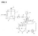
- FIG. 3 the basic structure of an embodiment of the method according to the invention is shown in overview.
- Fig. 5 then represents a special embodiment of the detail in detail.
- Fig. 3 the flowable starting material 2 to be grafted is conveyed from a reservoir 1 to the mass proportioning unit 7 (with a nozzle) with resonance excitation 8 in which the gassing takes place.
- the starting material 2 can be constantly moved to achieve a homogeneous phase as possible with a stirrer 3.
- a constant fluid level 4 is set in the reservoir 1 so that a quasi-constant admission pressure acts both on an installed pump 5 and on the mass proportioning device 7.
- the adjustment of the pressure can also be accomplished via a corresponding pressure gas superposition of the fluid level 4.
- the starting material 2 is fed via a pump 5 and subsequently via a mass flow meter 6, e.g. works according to the Coriolis measuring principle, promoted.
- the centrifugal pump 5 is advantageously speed-controlled via the reference variable mass flow, so that a constant mass flow to the mass proportioning device 7 is set.
- flowable starting material 2 is pressed through an opening in the form of a nozzle 7, which is considered here as part of a Masseproportionieres, under laminar flow conditions.
- the beam of the flowable starting material 2 a harmonic vibration (sinusoidal oscillation) is superimposed by means of electronically controlled electromagnet 8.
- the relevant for the detachment process acceleration a periodically introduced disturbance force is shifted by the phase ⁇ [rad] with respect to the amplitude x of the vibration.
- the starting material 2 initially forms a laminar flowing jet, which decays shortly after the nozzle opening 7, but with a corresponding distance from the nozzle, according to the laws of laminar jet disintegration.
- the drops 9 of the flowable starting material 2 then move along a movement path 50 in the direction of solidification liquid 11. If no additional forces introduced - e.g. aerodynamic forces - act on the drops 9, the drops fall down the gravity following.
- Another possibility for variation consists of changing the material properties, for example by changing the temperature, as a result of which the substance properties of viscosity, surface tension and / or density can be adapted to an optimal droplet image.
- the separate drops of the flowable starting material 9 are transferred into a solidification liquid 11 and thereby have to overcome a phase boundary.
- a phase boundary due to the surface tension of the solidification liquid 11, a high entrance barrier and thus damage to the droplet shape can be effected.
- the surface tension of the solidification liquid ⁇ solidification liquid should be less than 50 mN / m, in particular less than 30 mN / m and thereby the transition of the drops 9 can be accomplished faster.
- the reduction in the surface tension of the solidification liquid 11 can be achieved, in particular, in the case of polar solidification liquids 11 advantageously by the addition of surface-active or surface-reducing substances (for example surfactants).
- surface-active or surface-reducing substances for example surfactants.
- surfactants for example surfactants.
- the skilled person many opportunities are known.
- the chemical functional classes of the alkyl / aryl sulfates, sulfonates, phosphates, fluorates, ethoxylates, ethers, oxazolidines, pyridinates, sucinnates can be cited.
- the drops 9 are introduced at an acute angle ⁇ in the solidification liquid 11, in particular flowing solidification liquid 11, that is ⁇ ⁇ 90 °, the angle ⁇ as an angle between the tangent to the trajectories 50 of Drop 9 and the tangent to the surface of the solidification liquid 11, each defined at the point of introduction into the solidification liquid 11, in particular in a flowing solidification liquid is defined.
- This angle is in Fig. 3 . 6 . 7 . 8th . 13 . 15 . 16 and 17 shown in different views and embodiments.
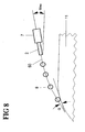
- Analogous angles can also result if the dripping into a static solidification liquid takes place and the mass proportioner 44 is moved (see Fig. 18 and 19 ) or the trajectory of the drops 9 by inclination of the mass proportioning 7 or a combination with a stationary and moving solidification liquid 11 is set (see Fig. 8 ).
- an acute angle ⁇ > 15 °, in particular> 45 °, in particular> 60 ° and very particularly> 70 ° is set ,
- a further measure for avoiding damage to the drop shape 9 upon entering the solidification liquid 11 can be accomplished by an upstream curing section, during the fall time of the droplets 9 of the flowable starting material 2. In this case, a sufficient hardening of the shell of the drop 9 is effected.
- the flowing solidification liquid 11 is guided laminarly relative to the movement speed of the drop / particle at the point of introduction, that is to say has a Reynolds number [Re] of less than 2320 and very particularly advantageous laminar flow conditions of the particle 10 flowing around in the region Re of FIG 0.5 to 500 and Froude Fr are optimally adjusted from 0.1 to 10, especially less than 5 and especially less than 2.
- the values for describing the flow conditions are obtained on the submerged and circulated particles shortly after the point of introduction.
- the optimized setting of the laminar flow conditions of the solidification liquid in particular shortly before the point of introduction, can be realized by longitudinal or rotating flows, in particular by pronounced and / or particularly advantageous fully developed flows of the longitudinal and rotating flow types.
- Distinct and fully developed flows are defined flows (for example, trombe, swirl) and / or in particular specially directed flows (wall boundaries, channel flow, etc.). These flows have the particular advantages that vortices and / or wall touch can be reduced.
- an angular momentum is induced due to the occurrence of pairs of forces between the drop 9 and the solidification liquid 11 guided at a certain angle ( Fig. 11, 12th
- This induced rotational movement further stabilizes the droplet 9 and subsequently also supports the reformation into a spherical solid article 10.
- This influence can advantageously be controlled by the angle of inclination and the relative speeds and / or by impressing velocity fields in two axes, For example, be used by an additional transverse component - eg by an additional tangential flow in a funnel with overflow edge next to the main flow direction (horizontal flow or vertical flow in a funnel with overflow edge) the liquid movement advantageous.
- a solidification liquid 11 and in particular a flowing solidification liquid offers substantial advantages compared to cooling in gas phase due to the higher heat capacity, density and thermal conductivity of the solidification liquid 11.
- the mass transfer is substantially increased by the set flow conditions relative to gas phases and / or static solidification liquids.
- advantageous initial conditions are guaranteed - e.g. Temperature, concentration at the point of entry of the drop 9 in the flowing solidification liquid 11 - and thus represent advantageous optimally adjusted parameters.
- the solidification liquid 11 is used as the coolant for the curing.
- the temperature of the solidification liquid By varying the temperature of the solidification liquid, optimized cure and reformation times to the spherical particle can be set.
- Particularly advantageous in the case of urea-containing or urea-containing melts is the use of a nonpolar coolant or a solidification liquid which has a freezing point below that of water, very particularly advantageously by setting a temperature of the solidification liquid 11 directly in front of the point of introduction of the droplets 9 of -20 ° C to + 20 ° C.
- the formation and / or chemical curing times can be deliberately controlled by varying the temperature of the solidification liquid.
- a low or non-wetting solidification liquid 11 can also be used to advantage in the storage of the spherical solid particles 10. It is preferred if, in particular, the urea particles 10 are conditioned with amino and / or oxitriazines and / or hydrocarbons.
- the conditioning leads to a better trickle flow of the solid particles and prevents caking.
- the conditioning agents can also be subsequently applied by spraying and / or granulation on the finished solid particles 10. It is particularly preferred if a fluid (solidification liquid 11) used in the production of the solid particle 10 simultaneously serves as a conditioning agent. In this way, the ball generation and the conditioning can be done in one step.
- the grafting for the method described above is exemplified by the Fig. 3 . 6 and 13 explained below.
- the mass proportioner 7, 8 causes the splitting of the jet into mass distributed droplets 9 - according to the above description Fig. 5 ,
- the damage and non-destructive transfer of the drops 9 in the solidification liquid 11, for example by the measures of the surface tension ( ⁇ Erslarrungswashkeit ⁇ drops ), the setting of an angle ⁇ and the reformation / stabilization (interfacial tension, polarity difference), curing (coolant) and / or the removal (flowing) of the spherical solid particles 10 is in detail in Fig. 6 and in a particular embodiment in Fig. 13 shown.
- the drops 9 After the transfer of the drops 9 into the solidification liquid 11, the drops 9 reform and cure into spherical solid particles 10.
- the drops 9 essentially follow a vertical trajectory 50 here.
- Fig. 3 Furthermore, it is shown that the solid particles 10 that are stabilized in shape and stabilized in the drip or in the gutter channel and enter into a storage container 13 for the solidification liquid 11.
- a mechanical separation unit 12 for example a screen basket, the hardened and spherical solid particles 10 are separated from the solidification liquid 11.
- the solidification liquid 11 is cooled, this being conducted via a heat exchanger 15 by means of a centrifugal pump 14 to the dropping apparatus.
- the heat of solidification dissipated in the heat exchanger 15 e.g., heat of crystallization
- the heat of solidification dissipated in the heat exchanger 15 may be raised to the melting temperature of the urea by means of a heat pump, followed by energy recovery and heat coupling. This is particularly advantageous in the grafting of melt phases.
- a pronounced in particular fully developed flow of the solidification liquid 11 is preferably defined by a fully developed flow channel, in particular in the form of a channel channel.
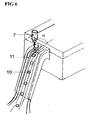
- a fully developed flow, especially in a gutter channel of the dripping apparatus, is in Fig. 6 shown.
- the generation of the advantageously usable angle ⁇ is effected with a flow-mechanically specially shaped overflow weir 31, which causes a very gentle deflection of the solidification liquid 11 (cooling liquid), wherein the contour of the overflow weir 31 is taken or imaged by the cooling liquid on the surface and following the acute angle ⁇ between the tangent to the trajectory 50 of the Drop 9 and the tangent to the surface of the flowing solidification liquid, each created at the point of introduction into the flowing solidification liquid 11, is generated.
- a fluidically specially shaped flow interference element 31 (see FIG Fig. 15 ) or particularly advantageously an adjustable flow disturbing body 31 in the form of a wing (see Fig. 16 ) used. Both embodiments in turn cause the formation or imaging of an acute angle ⁇ between the tangents to the trajectories 50 of the drops 9 and the tangent to the surface of the flowing solidification liquid, each applied to the point of introduction into the flowing solidification liquid.
- the hydrofoil flow body ( Fig. 16 ) has the advantages on the one hand in the rapid adaptation or change of the imaging angle and on the other hand in the setting of an underflow, so that a particularly advantageous rapid removal of the spherical particles 10 can be effected by the dripping area.
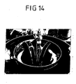
- the dropping into a funnel with overflowing solidification liquid has a similar effect ( Fig. 13 . 14 ).
- the supply of the solidification liquid 11, in particular the cooling liquid via a plurality of symmetrically arranged pipes 30.
- the solidification liquid 11 is fed either vertically and counter to the gravitational direction via a downwardly curved pipe or / and can be set in a swirling motion by tangentially arranged supply pipes.
- the first tube arrangement guarantees the vertical conveyance of the solidification liquid, so that a very calm and smooth surface can be adjusted.
- the second tube arrangement causes the twisting movement under calm flow conditions.
- the currents are fully developed. Further calming of the flow is achieved by widening the circular hopper construction from the ground towards the liquid level - equivalent to a type of diffuser.
- the specially shaped overflow weir 31 takes place the trouble-free transfer of the solidification liquid 11 in a funnel area.
- the specially shaped overflow weir 31 is transferred on the outside of the funnel tangentially from its inclination in a gentle circular segment-like curve, to this includes a kind of parabolic-shaped rounding, the leg of which runs very flat in the direction of the inner funnel (see Fig. 13 ).
- the liquid can be kept at a similar level over a longer period of time.
- the transition from the parabolic segment to the inner funnel wall again runs directed tangentially over a kind of more curved circle segment.
- All curved segments form a unit in itself and due to the tangential transitions to the funnel walls also an outwardly appearing closed unit.
- a further advantage of this shaping is the provision of a sufficiently high film thickness of the solidification liquid 11 in the guide channel. This advantageously prevents premature contact of the not yet sufficiently hardened urea particle 10 with the wall.
- liquid heights of 20-40 mm are advantageously set, measured as the distance between the tangent of the horizontally oriented overflow edge to the liquid level.
- the formation as well as the removal of the spherical solid particles 10 is advantageously carried out by the respectively prevailing flow velocity of the cooling liquid (solidification liquid 11). In a concrete application, this is about 0.2 to 0.8 m / s at the horizontal overflow edge, this value being only insignificantly changed by the special shape of the overflow weir as a function of the drop height.
- the rate of descent of the spherical urea particle 10 is at a diameter of about 2.5 mm at about 0.4 m / s.
- the spherical urea particle 10 is already formed after a few tenths of a second and sufficiently hardened. This means a completed formation and cooling process already after a few lengths in the upper part of the funnel, in particular after the visualized via a stroboscope ball image length of about 5 to 12 solid particles 10th
- the geometric design of the special overflow weir 11 takes place fluidically.
- baffles in particular tapered baffles for flow-mechanical guidance of the flow or to form a fully developed channel flow are introduced into the hopper.
- the baffles are tapered down, so that along the inclined funnel wall a sufficient liquid level remains formed and following wall contact of the spherical solid particles 10 can be prevented.
- the baffles can also be curved, so that the advantage of the twisting movement or the 2-dimensional flow fields can be utilized.
- a gutter is used instead of the funnel.
- the supply of the cooling medium is analogous to the above-mentioned description of a box having the vertically oriented pipe feeds, so that in turn results in a smooth and fluidically optimal feed flow.
- the flow is directed along walls and in the direction of a specially shaped bluff body, that of the overflow weir Fig. 13 corresponds, steered.
- the flow is again fully developed.
- the residence time necessary for the formation and hardening in conjunction with the flow velocity is defined over the length of the channel flow. In this case, can be advantageously adjusted by the width of the channel and correspondingly higher liquid heights.
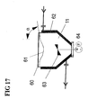
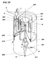
- the measures for producing a spherical solid particle 10 by the formation of a pronounced rotational flow, in particular by the formation of a Trombenform 61 accomplished in a stirred tank 60.
- a stirrer 63 arranged at the bottom, whose speed 64 can be varied to set a defined speed and the distance to the liquid surface, a gentle Trombenform is formed and following an angle ⁇ between the tangent to the trajectories 50 of the drops 9 and the tangent to the surface of the flowing solidification liquid 11, respectively created at the point of introduction into the flowing solidification liquid, is generated. Due to the swirling motion and under the influence of the centrifugal and Coriolis forces urea particles 10 show a helical trajectory, whereby the residence time is extended correspondingly advantageous.
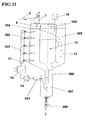
- a rotating container or a rotating solidification liquid 11 for producing solid particles 10 after Fig. 20 used.
- a circular channel channel delimited by the walls of two cylinders (ring) is formed in the outer region, so that a fully developed rotational flow is generated.
- the solidification liquid 11 is supplied via a mechanical seal at the bottom of the container 201.
- the solidification liquid 11 is conveyed via a riser 202 into an annular distribution device 203/204 with inlet openings, in particular hole openings 205, into the actual dripping area 206.
- the inlet openings 205 of the distributor device are arranged just below the surface of the solidification liquid, somewhat below the actual dropping point.
- Both the spherical solid particles 10 and the solidification liquid 11 are forced by the flow into the bottom region of the rotating container.
- the solids particles 10 are separated by gravity or by a screen mesh from the slightly heated solidification liquid 11, either by a conical and widening collecting area 209.
- the solidification liquid 11 freed from the urea particles 10 rises against the force of gravity into the discharge line Return region 207, which is formed by a geodetically slightly lower inwardly disposed funnel with respect to the actual level of solidification liquid 11 at the point of dropping.
- the spreading of the spherical urea particles 10 is carried out by discontinuously opening the obturator 210, wherein the spherical urea particles 10 are thrown together with a small portion of the solidification liquid 11 due to the centrifugal forces from the container in an external collecting and separating apparatus. All other system components, such as mass proportioners, heat exchangers are similar to the previous descriptions.
- the solidification liquid 11 is tangentially 302, 303 fed into the annular area (two cylinders) of a standing container.
- the inner cylinder no funnel for discharging the fluid phase
- the effects are similar to those of the rotating container with the formation of a helical movement 305 of the solid particles 10 and the advantageous extension of the residence time and the possible adjustment of an inclined surface of the solidification liquid 11 at correspondingly high peripheral speeds.
- the separation of the solid particles from the solidification liquid is carried out in the usual way with a known separation device such as a cyclone 307 or a wire mesh or sieve 12.
- a known separation device such as a cyclone 307 or a wire mesh or sieve 12.
- the advantage of the apparatus is found in the quasi-continuously shapable discharge of the spherical solid particles 10 via the shut-off valve 308, the level 102 of the solidification liquid 11 can be maintained by the closed system or the make-up is effected via a level gauge 16. All other system components, such as mass proportioners, heat exchangers are similar to the previous descriptions.
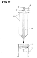
- Fig. 27 is a Zertropfung a flowable starting material, in particular a suspension based on a ceramic material and a binder, shown in a static solidification liquid 11.
- This has two mutually immiscible or immiscible phases or substances of different polarities and / or different densities.
- the separate drops 9 of the mass proportioner are in this case introduced into a non-polar and light phase of the solidification liquid 11, which has a low surface tension, in particular of less than 30 mN / m.
- this first phase of the solidification liquid predominantly the reformation of the still flowable drops 9 to spherical, still flowable droplets 9.
- the solidification or hardening takes place in the second, denser phase of the solidification liquid 11 to the spherical solid particles 10. It is on a low interfacial tension pay particular attention between the lighter and denser phase of the solidification liquid. This should advantageously have a value of less than 10 mN / m.
- the hardened spherical solid particles 10 are separated in the usual way via a separator, for example via a sieve or filter 12 of the heavier phase of the solidification liquid and fed the separated solidification liquid in turn to the apparatus. All other system components, such as mass proportioners, heat exchangers are similar to the previous descriptions.
- Fig. 9 is a particularly advantageous embodiment of the shell hardening illustrated by the example of the production of spherical urea particles, in which the atomization of a cooling liquid 21 is effected by means of two-fluid nozzles 20.
- a plurality of two-component nozzles 20 are arranged on the cover of the upstream curing path in a circular symmetry and at a certain angle ⁇ two-substance nozzle to the drop axis of the urea drops 9.
- a cooling medium 21 in particular nonpolar hydrocarbon compounds, is sprayed into a kind of spray mist or to an aerosol.
- This aerosol has significant advantages over polar urea because of its non-polar character because the interaction of the non-"contracting" or quasi-mutually insoluble compounds forms the smallest surface of a body. This is a ball. As a result, the shaping is further supported.
- the formation of the finest droplets of the fluid into an aerosol promotes heat dissipation significantly, since the creation of a very large heat exchange surface (surface of the fluid droplets) and the wetting can be used to advantage. As a result, the necessary cooling sections can be kept very small.
- a pure draining method may be used in which the drops 9 are not generated by dividing a laminar flow.
- a simple device which has a perforated plate 40.
- This perforated plate 40 is arranged below a reservoir 41 for the flowable starting material, for example urea melt.
- a plurality of individual nozzles 42 is arranged, which represent holes in the perforated plate 40 in the simplest case.
- the nozzles may also have a funnel-like contour tapering from top to bottom, so that the flowable starting material is well guided through the nozzles 42.
- a pressure difference across the nozzle plate 40 is applied, individual droplets 9 drip from the nozzles 42, whereby the perforated plate 40 with the nozzles 42 acts as a mass proportioner.
- the embodiment Since the flow process is not external, e.g. is excited by vibrations, the drops 9 form solely under gravity. This usually takes longer than a high-frequency excitation of the Zertropfungsakuen.
- the embodiment has the advantages that a large amount of nozzles 42 can be arranged on a perforated plate 40.
- the solidification of the drops 9 to solid particles 10 can then take place in a manner as described in the other embodiments.
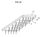
- Fig. 19 shows a perspective view of a round perforated plate 40, on the circumference of a wall 43 is arranged.
- the wall 43 forms, together with the perforated plate 40, the reservoir 41.
- the nozzles 42 for the passage of the flowable starting material are arranged on the circumference of the perforated plate 40.
- a supply line 44 Through a supply line 44, the flowable starting material is brought into the reservoir, wherein the supply line 44 is set in the promotion in rotation.
- the exiting flowable starting material experiences an acceleration toward the outside in the direction of the wall 43; the starting material is pressed against the wall 43.
- a defined pressure can be set at the nozzles.
- the nozzles 42 then convey the flowable source material away from the nozzle plate 40.
- this embodiment can also be designed so that the feed line 43 rests and the perforated plate 40 rotates.
- the nozzles 42 are arranged in the wall 43.
- a preferred embodiment of the urea particles according to the invention has a sphericity of ⁇ 0.923, especially ⁇ 0.940, in particular ⁇ 0.950, in particular ⁇ 0.960, in particular of ⁇ 0.970 and very particularly of ⁇ 0.980.
- urea particles having a diameter between 1,000 microns and 4,000 microns, preferably between 1,000 and 3,200 microns, preferably between 1,100 and 3,000 microns, preferably between 1,500 and 3,000 microns, and most preferably between 1,100 to 1,300 ⁇ m or 1,400 to 1,600 ⁇ m or 1,800 to 2,000 ⁇ m or 2,400 to 2,600 ⁇ m with a relative standard deviation of ⁇ 10%, preferably ⁇ 5%,%, preferably ⁇ 4%, in particular ⁇ 3.5%, are characterized:
- the invention contains the knowledge that, while maintaining the abovementioned method steps, a wide variety of solid particles 10 with high sphericity and narrow size distribution can be produced. If e.g. When a urea melt is used as the starting material, it is possible to produce unique urea particles 10
- urea particles 10 according to the invention are particularly suitable in a catalyst of a motor vehicle for the reduction of nitrogen oxides.
- the sphericity is calculated from the minimum and maximum Feret diameters, which are defined in the standard DIN 66141 and determined according to the ISO standard CD 13322-2.
- the sphericity is a measure of the accuracy of the rolling motion of a solid particle 10, especially during delivery in a dosing apparatus.
- the grain density in particular the mean grain density, according to the E-Norm 993-17 DIN-EN from 1998, the ratio of the mass of an amount of grains (ie of the material) to the total volume of the grains including the volume of closed pores in the grains Understood.
- the grain density is measured by the method of mercury displacement under vacuum conditions.
- circular and gap-shaped, in particular open pores with a defined diameter are filled with mercury using a specific pressure, thus determining the volume of the material.
- the grain bulk density is calculated in this way.
- Advantageous ranges for the mean grain density of urea particles are values between 1.250 and 1.335 g / cm 3 , in particular between 1.290 and 1.335 g / cm 3 . It is also advantageous if the mean grain density is between 1.28 and 1.33 g / cm 3 , especially between 1.29 and 1.30 g / cm 3 .
- the minimum Feret diameter and the maximum Feret diameter are defined in the standard DIN 66141 and are determined according to the ISO standard CD 13322-2, which deals with the particle size determination of substances by dynamic image analysis.
- This digital snapshots of the particles are dosed, for example, via a conveyor trough and fall down, added.
- the digital snapshots represent the projected areas of the individual particles in the different positions of the movement.
- the digital snapshots are used to calculate particle diameter and grain shape data for each individually registered particle, and perform statistical analyzes on the total number of particles collected per sample.
- Advantageous embodiments for the urea particle 10 have the following mean minimum Feret diameter: less than or equal to 4 mm, in particular between 2 and 3 mm, with a relative standard deviation of less than or equal to 5%. Furthermore, it is advantageous if the mean minium-Feret diameter of the urea particle 10 in the range between 2.2 and 2.8 mm with a relative standard deviation of less than or equal to 4%. It is very advantageous if the mean minimum Feret diameter is in the range between 2.4 and 2.6 mm with a relative standard deviation of less than or equal to 3.5%.
- the Feret diameter is the distance between two tangents that are applied to the grain perpendicular to the measuring direction.
- the minimum Feret diameter is thus the shortest diameter of a grain, the maximum Feret diameter the longest diameter of a grain.
- Urea particles 10 according to the invention have a sufficiently large mass constancy, i.
- the urea particles 10 are sufficiently equal to each other, so that the constancy of the particle dosage is comparable to the Dosierkonstanz a fluid.
- the mass constancy of the investigated particles is as follows: diameter Number of particles 1000 200 100 10 2.5 ⁇ 0.1 mm ⁇ 10% ⁇ 10.5% ⁇ 11% ⁇ 18% 1.9 ⁇ 0.1 mm ⁇ 10% ⁇ 10.5% ⁇ 11% ⁇ 18%
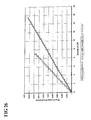
- the pore distribution indicates how many pores of a certain pore size the urea particles 10 have.
- the stated pore distribution of the urea particles 10 shows that comparatively many pores of small diameter and few pores of large diameter are present. This leads to a high strength of the urea particles 10.
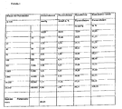
- Table 1 shows the numerical representation of the above semilogarithmic diagram.
- the percentage pore volume fractions are given as a function of the pore size of the urea particles 10.
- the table shows, for example, that 58.15% of the total pore volume is accounted for by pores having a pore radius of less than or equal to 50 nm.
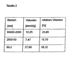
- the entire occurring pore diameter range was divided into 3 representative subregions and shown in Table 2: Of a total of 100% of the total pore volume present, 25.89% account for pores with a diameter between 2000 and 60000 nm, further 15, 79% account for pores with a diameter between 60 and 2000 nm and finally more than half, namely 58.32% of the volume accounts for pores with a diameter between 2 and 60 nm.
- the urea particles 10 have an average pore volume of less than 120 mm 3 / g, particularly less than 60 mm 3 / g, very particularly from 30 to 60 mm 3 / g, in particular less than 30 mm 3 / g, measured according to DIN 66133, on.
- the pore volume indicates the volume of the pressed into the pores of mercury based on 1 g sample mass.
- the porosity is the ratio between the pore volume and the external volume of the sample. It therefore indicates how much space of the total volume of pores is taken (%).
- the measurement of the pore distribution is carried out according to DIN 66 133 on the measurement of the pressed into a porous solid volume of mercury depending on the applied pressure. From this, the pore radius can be calculated using the so-called Washburn equation.
- the impressed volume as ordinate as a function of the pore radius as abscissa gives the graphical representation of the pore distribution.
- urea particles 10 which have an average pore radius of less than 25 nm, particularly preferably less than 17 nm.
- Balls with a small pore radius have a particularly high strength. This is for a good abrasion behavior in the dosage and storage advantageous.
- a urea particle has an average porosity of less than or equal to 7, in particular of less than or equal to 6%, measured according to DIN 66133.
- the sphericity of the particles was measured with the Camsizer 187 device (Retsch Technology, software version 3.30y8, setting parameter: use of a CCD zoom camera, area light source, 15mm groove, baffle, 1% particle density, frame rate 1: 1, measurement in 64 directions) according to the ISO standard CD 13322-2 and evaluated according to DIN 66141.
- SPHT 1 for a spherical particle and SPHT ⁇ 1 for other particle shapes.
- Sphericity is a measure that characterizes the unrollability of the particles during production. A good unrollability of the urea particles 10 leads to a reduction of the delivery resistance and minimizes the tendency of the urea particles 10 to get caught. This facilitates the metering.
- the urea particle 10 is conditioned with amino and / or oxytriazines and / or hydrocarbons.
- the conditioning leads to a better trickle flow of the particles and prevents the caking of the urea particles 10 during storage. It is particularly advantageous to use as conditioning agents aliphatic hydrocarbons or melamine and melamine-related substances.
- the conditioning agents can be subsequently applied by spraying onto the finished urea particle 10.
- a coolant used in the production of the particle simultaneously serves as a conditioning agent. In this way, no subsequent process step for conditioning longer necessary.
- the urea spheres have an average specific surface area of more than 5 m 2 / g, in particular more than 9 m 2 / g. This is the specific surface of the pores in the interior of the particle, measured according to DIN 66 133.
- urea particles 10 An important advantage of the urea particles 10 is their high breaking strength and hardness (elongation at break), which can be attributed to the microstructure or the microstructure of the embodiments.
- one embodiment of the urea particles has a breaking strength distribution in which 10% have a breaking strength of greater than 1.1 MPa, 50% a breaking strength of 1.5 MPa and 90% a breaking strength of 2.1 MPa.
- a breaking strength distribution is present in which 10% have a breaking strength of greater than 1.4 MPa, 50% have a breaking strength of 2.2 MPa and 90% have a breaking strength of 2.8 MPa.
- the embodiments of the urea particles 10 have a relative elongation at break of less than or equal to 2%, in particular of less than or equal to 1%.
- the breaking strength of the embodiments of the particles was measured using a granule strength test system GFP from M-TECH.
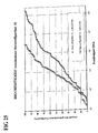
- Fig. 25 For two embodiments of the urea particles 10, the cumulative curve of the breaking strength distribution is shown.
- Fig. 26 the change in length during the loading of the urea particles 10 is shown with a breaking force.
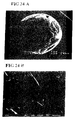
- Fig. 23A shows an embodiment of the urea particle 10 according to the invention with an average diameter of about 1.9 mm.
- the surface of the urea particle 10 has a finely crystalline outer shell.
- the high sphericity is recognizable.
- Fig. 23B shows a sectional view in which the homogeneous microstructure is recognizable, in particular the amorphous structure in most of the image.
- Fig. 24A shows as a further embodiment a technically prilled urea particle with an average diameter of about 1.9 mm.
- Fig. 24B shows a crystalline microstructure of the particle according to Fig. 24A , In Fig. 24B small crystallites are recognizable.
- an embodiment of the urea particle 10 according to the invention has a finely crystalline outer shell. It is particularly advantageous if a maximum crystallite size of less than or equal to 20 .mu.m, especially less than 1 .mu.m, in particular less than or equal to 0.1 .mu.m, especially if an amorphous structure is present.
- urea particles 10 whose biuret content is less than or equal to 20% by weight, especially less than 12% by weight, in particular less than or equal to 7% by weight, in particular less than or equal to 5% by weight, very particularly less than 2% by weight.
- the water content is less than or equal to 0.3% by weight. If the water content is too high, there is a risk of caking of the particles.
- the aldehyde content is less than or equal to 10 mg / kg and / or the content of free NH 3 is less than or equal to 0.2% by weight, in particular less than or equal to 0.1% by weight.
- the total content of alkaline earth metals is less than or equal to 1.0 mg / kg, in particular less than or equal to 0.7 mg / kg.
- the total content of alkali metals is less than or equal to 0.75 mg / kg, in particular less than or equal to 0.5 mg / kg.
- the proportion of phosphate is less than or equal to 0.5 mg / kg, in particular less than or equal to 0.2 mg / kg.
- the proportion of sulfur is less than or equal to 2.0 mg / kg, in particular less than or equal to 1.5 mg / kg, very particularly less than or equal to 1.0 mg / kg.
- the proportion of inorganic chlorine is less than or equal to 2.0 mg / kg, in particular less than or equal to 1.5 mg / kg, very particularly less than or equal to 1.0 mg / kg.
- the impurities are of particular importance for use in connection with catalytic exhaust gas purification.
- solid particles obtainable by the process according to the invention are particles of a ceramic material.
- a preferred embodiment of the solid particles made of a ceramic material is characterized by a sphericity of greater than or equal to 0.960, in particular equal to or greater than 0.990. Further preferred embodiments of the solid particles of a ceramic material are by a diameter between 100 microns and 2,500 microns, with a relative standard deviation of ⁇ 5%, preferably ⁇ 4%, in particular ⁇ 1%, and moreover by a diameter between 300 microns and 2,000 ⁇ m, with a relative standard deviation of ⁇ 3.5%.
- ceramic solid particles which are characterized in that the ceramic material is a ceria-stabilized zirconium oxide having a CeO 2 content of 10 to 30% by mass. Furthermore, these solid particles are characterized by a grain density (after sintering) in the range between 6.100 and 6.250 g / cm 3 .
- Examples 1 to 4 and 7 relate to the production of urea particles 10 and Examples 5 and 6 on the production of balls of a ceramic material.
- the melting vessel 1 has a steam-heated double jacket (not shown). By means of an electrically heated immersion heater saturated steam with an overpressure of 1.95 bar was generated in the outer jacket, which serves as a heating medium for the purpose of melting. of urea in the inner container.
- the urea was stirred continuously by means of a slow-moving stirrer 3, here a blade stirrer.
- the relevant material values of the urea melt are the melt phase density of 1.246 kg / dm 3 , the surface tension of 66.3 mN / m and the dynamic viscosity of 2.98 mPas at the corresponding melt phase temperature of 135.3 ° C.
- the continuously guided, shaping and stabilizing solidification liquid 11 is fed via a reservoir 13 by means of a centrifugal pump 14 via a cooled by glycol / water mixture heat exchanger 15 in the circuit to the dropper.
- the cooling brine, medium glycol / water [20% by weight] is guided by means of a centrifugal pump on the secondary side in a separate cooling circuit via a cooling unit of the connected load of 3.2 kW to 0 ° C.
- the cooling brine cools both the reservoir 13 and the heat exchanger 15.
- the cooling surface of the heat exchanger 15 was 1.5 m 2 .
- an aliphatic hydrocarbon mixture of the type Shell Sol-D-70 [SSD-70] is used as a continuously guided solidification liquid 11.
- the solidification liquid 11 has a surface tension of 28.6 mN / m at 20 ° C and is thus smaller than that of the urea melt 2 at 66.3 mN / m.
- the solidification liquid 11 is quasi completely non-polar and practically barely or not wetting with respect to the urea, this means the wetting angle ⁇ > 90 °.
- the density of the solidification liquid 11 at the operating point is 801 kg / m 3 .
- the SSD-70 phase was cooled to inlet temperatures in the dropper at about 0 ° C.
- the flow rate of the non-polar fluid phase (solidification fluid) was 1.5 m 3 / h. This is conveyed by means of a centrifugal pump 14 via the heat exchanger 15 in the dropper.
- the solidification liquid 11 is first led vertically upwards and calmed over a widening flow cross section (diffuser), so that the set level of liquid "flat and smooth” or calm visually appears. There is a smooth dripping area.
- the solidification liquid 11 flowed through a specially shaped overflow edge 31 into a groove with a width of 27 mm and a length of 220 mm.
- the overflow edge of the dropper showed a parabolic shaped tangential shape merges into the straight part of the gutter that defines the hardening section. This is in the Fig. 6 shown schematically.
- the solidification liquid 11 is subsequently directed directed via a laterally limited groove in the storage tank 13. It develops a fully developed and flowing flow in the gutter.
- the vibration system was activated to activate the periodic disturbance force.
- the periodic disturbing force is harmonious and shows a sinusoidal deflection (amplitude) via a motion detector on a HAMEG HM 303-6 oscilloscope.
- the excitation frequency was - in the case of the production of spherical urea balls in a diameter range between 2.4 to 2.6 mm - 124.6 Hz and was set with the combined frequency generator and amplifier type TOELLNER TOE 7741.
- the amplitude of the oscillation was set on the potentiometer of the device (position 2).
- a shut-off valve in the supply line of the melt phase to the mass proportioner 7 was opened and adjusted by means of gear pump by variation of the frequency-controlled speed, a mass flow of 5.6 kg / h. Both the pump head and the supply line were steam-heated on the outside.
- the mass flow was displayed with the aid of an inductive mass flow meter 109 or regulated as a controlled variable of the speed via a PID hardware controller following in automatic mode.
- the defined mass flow was fed to the mass proportioner 7, 8, wherein the nozzle diameter was 1.5 mm.
- the melting phase is excited by the vibration.
- the set flow conditions correspond to those of the laminar jet decay with resonance excitation. Under these conditions, a so-called "standing" drop image ( Fig.
- the approximately mass-equivalent drops 9 produced by the resonance excitation of the laminar jet decay were introduced into the continuously guided fluid phase (solidification liquid 11) at an acute angle ⁇ of approximately 75 °.
- the fluid, SSD-70 showed a velocity of 1.01 m / s shortly after the dropping point. This corresponded to a re-number of about 260 short after the dropping point according to the relative velocity between solid particles 10 and fluid (solidification liquid 11).
- the submerged and subsequently still further decreasing solid particles 10 were entrained by the fluid flow and were discharged after sufficient hardening by cooling in the positioned below fluid reservoir 13. In this was a sieve basket 12, through which the spherical urea particles 10 could be separated from the fluid phase (solidification liquid 11).
- urea particles 10 with a sphericity of 0.974 could be produced.
- the particle size distribution of the entire fraction is normally distributed and was between 2.3 to 2.7 mm.
- Around 84.7 mass% of the produced urea particles 10 were in the diameter range of interest between 2.4-2.6 mm and showed a high density of 1.2947 kg / dm 3 : In terms of sphericity, there is a relative diameter deviation of ⁇ 3 , 4%.
- spherical urea particles 10 having a mean diameter d 50 of approximately 2.7 mm were produced by varying or increasing the mass flow of the melt. In this case, the mass flow was increased from previously 5.6 kg / h to 6.6 kg / h.
- the addition of the continuous solidification liquid 11 [SSD-70] was also increased in parallel from 1.5 to 2 m 3 / h.
- the adjusted liquid level, at a flow of about 2 m 3 / h, was about 27 mm at the overflow edge, ie at the point at which the liquid is first accelerated under the influence of gravity.
- the approximately mass-equivalent drops 9 produced by the resonance excitation of the laminar jet decay were introduced into the continuously guided solidification liquid 11 at an acute angle ⁇ of approximately 78 °.
- the SSD-70 showed a velocity of 1.04 m / s shortly after the dropping point. This corresponded to a re-number of about 400 shortly after the dropping point corresponding to the relative velocity between solid particle 10 and fluid (solidification liquid).
- an initially visually observable improvement of the drop shape to "more spherical" particles takes place after about 100 milliseconds or about 1/3 of the distance traveled in the solidification liquid, moreover, the spherical solid particles 10 lost the transparent appearance of the melt phase and appeared opaque.
- urea particles (10) with a sphericity of 0.974 could be produced as solid particles.
- the grain size distribution of the entire fraction is normally distributed and was between 2.5 to 2.9 mm.
- About 82.3 mass% of the produced urea particles 10 were in the diameter range of interest between 2.6-2.8 mm and showed a high density of 1.2953 kg / dm 3 . In terms of sphericity, there is a relative diameter deviation of ⁇ 3.7%.
- spherical particles of urea 10 having a mean diameter d 50 of about 1.9 mm were prepared as solid particles.
- the mass flow of the melt was 2.2 kg / h.
- Cooling flow [solidification liquid SSD-70] was set to 1.0 m 3 / h.
- the approximately mass-equivalent drops 9 produced by the resonance excitation of the laminar jet decay were introduced into the continuously guided solidification liquid 11 at an acute angle ⁇ of approximately 71 °.
- the SSD-70 showed a velocity of 0.9 m / s shortly after the dropping point. This corresponded to a Re number of about 54 just after the dropping point corresponding to the relative velocity between particle and fluid.
- an initially visually observable improvement of the droplet shape to "more spherical" particles occurs after about 100 milliseconds or about 1/3 of the distance covered in the solidification liquid, wherein moreover the spherically shaped particles lost the transparent appearance of the melt phase and appeared opaque.
- urea particles 10 with a sphericity of 0.983 could be produced.
- the grain size distribution of the entire fraction is normally distributed and was between 1.7 to 2.1 mm.
- About 85% by weight of the produced urea particles 10 were in the diameter range of interest between 1.8-2.0 mm and showed a high density of 1.2957 kg / dm 3 .
- a relative diameter deviation of ⁇ 1.7% In terms of sphericity, a relative diameter deviation of ⁇ 1.7%.
- the rotating container ( Fig. 20 ) into the system. All other system components were identical to example 1.
- the dynamic viscosity of SSD-70 was 2.54 mPas.
- the density of the solidification liquid at the operating point was 802.7 kg / m 3 .
- the SSD-70 phase was cooled to an inlet temperature in the rotating vessel of minus 4.1 ° C.
- the flow of the solidification liquid was conveyed by means of a centrifugal pump via the heat exchanger in the rotating container and was 1.5 m 3 / h.
- the solidification liquid 11 is first introduced at the bottom via a horizontal inlet nozzle 201 into the container. It is then guided vertically upwards in a riser 202 into a cylindrical annular region 203 which is attached to the inside of an annular cylinder 204. Via holes 205, which are mounted in the annular cylinder 204 over the entire circumference at the height of the cylindrical ring area, the cold solidification liquid 11 enters the dripping area 206. From here, the solidification liquid 11, which is heated by the dripping of the hot urea melt, forcibly flows into the dripping area 206 Interior of the annular cylinder to the bottom or collecting area 209 of the rotating container.
- the separation of the urea particles 10 from the solidification liquid 11 either by gravity or by a sieve installed there.
- the warm solidification liquid is discharged 208 through an inner hopper 207 and a drain pipe from the rotating container. Due to this flow, a flat liquid level of cold solidification liquid 11 forms in the dripping area.
- the rotation of the solidification liquid 11 is through a toothed pulley via a geared motor at the bottom of the container 211 causes.
- the heat of crystallization of the urea melt is continuously discharged with the solidification liquid 11 from the rotating container and discharged through the integrated heat exchanger.
- the heated solidification liquid 11 is recooled via the reservoir 13 and the heat exchanger 15 and recirculated.
- the urea melt was dripped under the same conditions as described in Example 1.
- the nozzle diameter was 1.0 mm.
- the immersion of the droplet collective took place after the 5th particle of the standing droplet image.
- the point of entry of the droplets into the continuously guided fluid phase 11 had a distance of 28 mm from the fluid surface to the nozzle in the direction of the nozzle axis (vertically measured distance).
- the horizontal distance of the drop to the inside of the container wall was 40 mm.
- the radius of the dropping point measured from the line of symmetry of the rotating container was 65 mm.
- the angular velocity of the container was measured at 75 rpm.
- the approximately mass equivalent drops (9) generated by the resonance excitation of the laminar jet disintegration were introduced into the rotating, leveled fluid phase.
- the fluid, SSD-70 had a peripheral velocity of 0.51 m / s directly at the point of dripping. This corresponded to a Re number of 156.7 shortly after the dropping point corresponding to the relative velocity between particle and fluid and a Fr number of 5.39.
- the submerged particles were directed to the vessel bottom in a downward, spiraling motion due to the force of forces acting on the individual particles resulting from weight, buoyancy, resistance and Coriolis forces. During this phase, the hardening process of the urea particles took place.
- the hardened urea particles were collected in the collection area 209 and discharged discontinuously, with the aid of the outlet cock 210 from the rotating container.
- urea particles 10 with a sphericity of 0.970 could be produced.
- the grain size distribution of the entire fraction is normally distributed and was between 1.7 to 2.1 mm.
- About 85.8 mass% of the produced urea particles 10 were in the diameter range of interest between 1.8-2.0 mm and showed a high density of 1.2952 kg / dm 3 .
- the aqueous suspension was then dispersed with the dispersing IKA, type: Ultra Turax D50, or the ceramic Bonding agent in the aqueous suspension of the oxides homogenized.
- the dispersed suspension had a residual moisture content of 48.5% by mass, a dynamic viscosity of 3.6 dPas and a surface tension of 43.5 mN / m.
- an aqueous alcoholic calcium chloride solution was used as a hardening, stabilizing and shaping solidification liquid 11. It was a solidification liquid 11 made of two completely miscible substances of different polarity.
- the concentration of the less polar component ethanol compared to the droplet medium (finished suspension) was 25% by mass.
- 1 mass% CaCl 2 was dissolved.
- a surface tension of 42.5 mN / m of the alcoholic CaCl 2 solution can be measured. This is smaller than that of the finished suspension with 43.5 mN / m.
- the density of the hardening solution was 1.001 kg / dm 3 .
- Example 2 The solution was as described in Example 1 from the reservoir via a centrifugal pump, but without cooling circuit, promoted to Masseproportionierer. Curing takes place by the divalent calcium ions in conjunction with the added ceramic binder ammonium alginate.
- the vibration system - as described in Example 1 - was activated.
- the frequency of the excitation was 334.5 Hz and the amplitude position was 1.5.
- a mass flow of 0.36 kg / h was set.
- the nozzle diameter was 0.3 mm.
- the set flow conditions correspond to those of the laminar jet decay with resonance excitation.
- the approximately mass-equivalent drops 9 produced by means of the resonance excitation of the laminar jet decay were introduced into the continuously guided solidification liquid 11 at an acute angle ⁇ of approximately 72 °.
- the solidification liquid 11 was an ethanolic CaCl 2 solution at a rate of 0.90 m / s at the dropping point. This corresponded to a re-number of about 45.
- the hardening of the spherical particles takes place in this example by ion exchange between the Ca 2+ ions present in the hardener solution and the ammonium ion present in the suspension. Due to the nonpolar portion of the hardener solution, this is the ethanol, the curing is not abrupt, but again after about 1/3 of the distance covered by the hardener section successively from outside to inside by gelling.
- ceramic particles with a sphericity of 0.991 could be produced after drying and sintering.
- the particle size distribution of the entire fraction is normally distributed and was between 0.33 and 0.56 mm after the following drying and sintering.
- About 92.7 mass% of the ceramic particles produced were in the range of 0.36-0.5 mm in diameter of interest.
- the d 50 was 0.43 mm and the spherical particles had a high density of 6.18 kg / dm 3 .
- the sphericity shows a relative diameter deviation of ⁇ 0.3%.
- a dropping method is used in this embodiment.
- very small and minute urea particles 10 with an approximate spherical shape are produced with high constancy.
- Fig. 5 is the basic structure of a Vertropfungs worn shown.
- Urea melt 2 is pressed through a nozzle 7, wherein the nozzle 7 is set in vibration S.
- a laminar flow corresponding to the material data of the urea system, is set in the nozzle 7.
- the urea melt is virtually dropped after the nozzle opening 2; Spherical urea drops 9 are formed.
- the harmonic vibration force imparted to the urea melt corresponds to the first harmonic of the urea system. In this case, an amplitude of 2.5 mm was set. The frequency of the oscillation was 124 Hz. The temperature of the melt was about 136 ° C.
- the vibrational force pressed on the urea melt causes a so-called laminar jet disintegration, which favors the mass constancy of the balls.
- the harmonic Oscillation is a kind of predetermined breaking point in the urea melt jet causes, so that almost always the same size urea particles 10 are formed (quantity proportioning).
- the driving force of the separation, the weight, the vibration force is added.
- the restraining forces in this case are the surface tension force and the buoyancy force which counteract the resulting peel force.
- slightly smaller drops 9 can be generated at the same volume flow and nozzle diameter.
- a so-called standing droplet image which in Fig. 4 is shown.
- the droplet distribution corresponds more or less to a monomodal distribution.
- the second to fifth ball of the standing wave shows the best spherical shape, and from that point on or locally the shell stabilization should be initiated by rapid cooling.
- the urea particles 10 produced using one embodiment of the method according to the invention were analyzed.
- the fracture strength of the embodiments of the particles compared to urea technically prilled unconditioned was measured with a tablet breakage strength tester TBH 300 S from. ERWEKA. Breaking strength is given in the dimension force required to break a particle between two parallel plates, and is referred to the particle cross-section in the equatorial plane of the urea particle 10.
- the pore volume, the specific surface area, the average pore radius and the porosity were measured by means of Hg porosimetry according to DIN 66 133 by measuring the volume of mercury injected into a porous solid as a function of the applied pressure. Furthermore, the grain density was measured according to the standard EN 993-17 by means of mercury displacement under vacuum conditions. The apparent density has approximately the same value as the density of the base material. The difference comes about through the pores and closed cavities, into which the mercury can not penetrate (g / cm 3 ).
- the average pore radius of the urea particles 10 according to the invention is lower by about 2 orders of magnitude than that of the known particles. Also, the specific surface area is significantly larger than that of the known urea particles
- the urea particles 10 are used in the selective catalytic reduction (SCR) of nitrogen oxides in a motor vehicle.
- the SCR is a suitable measure (see Bosch, Kraftfahrisches Taschenbuch, 25th edition, 2003, p. 719 ).
- the SCR is based on ammonia reducing nitrogen oxides to nitrogen and water in the presence of a selective catalyst.
- the nitrogen oxides NO x are catalytically reduced to N 2 and H 2 O by means of the NH 3 released from the urea.
- urea is injected into the exhaust gas stream in aqueous solution.
- the urea solution (a 32.5% solution) is used because of its good dosing.
- the urea particles 10 are so uniform, i. they have such a close tolerance for their mass that the uniformity of the dosage can be achieved with the urea particles 10 according to the described embodiments instead of with a liquid solution. Due to the much higher concentration of active compound compared to the aqueous solution (32.5%) and due to their much smaller volume, the solid particles allow more favorable transport and storage conditions.
- urea particles 10 of the invention is not limited to the SCR technique, but any other technical applications are conceivable.
Landscapes
- Chemical & Material Sciences (AREA)
- Engineering & Computer Science (AREA)
- Organic Chemistry (AREA)
- Chemical Kinetics & Catalysis (AREA)
- Ceramic Engineering (AREA)
- Environmental & Geological Engineering (AREA)
- Manufacturing & Machinery (AREA)
- General Chemical & Material Sciences (AREA)
- Materials Engineering (AREA)
- Oil, Petroleum & Natural Gas (AREA)
- Analytical Chemistry (AREA)
- Structural Engineering (AREA)
- Biomedical Technology (AREA)
- Health & Medical Sciences (AREA)
- Composite Materials (AREA)
- Inorganic Chemistry (AREA)
- Combustion & Propulsion (AREA)
- Mechanical Engineering (AREA)
- Glanulating (AREA)
- Inorganic Compounds Of Heavy Metals (AREA)
- Physical Or Chemical Processes And Apparatus (AREA)
- Organic Low-Molecular-Weight Compounds And Preparation Thereof (AREA)
- Fertilizers (AREA)
- Pigments, Carbon Blacks, Or Wood Stains (AREA)
- Crushing And Grinding (AREA)
- Exhaust Gas Treatment By Means Of Catalyst (AREA)
- Manufacturing Of Micro-Capsules (AREA)
Applications Claiming Priority (3)
| Application Number | Priority Date | Filing Date | Title |
|---|---|---|---|
| DE102005018949A DE102005018949A1 (de) | 2005-04-18 | 2005-04-18 | Harnstoffpartikel, Verfahren zu dessen Herstellung und dessen Verwendung |
| AT0202605A AT502777B1 (de) | 2005-04-18 | 2005-12-19 | Verfahren zur herstellung von partikeln aus einem keramischen werkstoff |
| EP06742646A EP1874450B1 (de) | 2005-04-18 | 2006-04-18 | Keramikpartikel |
Related Parent Applications (1)
| Application Number | Title | Priority Date | Filing Date |
|---|---|---|---|
| EP06742646.0 Division | 2006-04-18 |
Publications (1)
| Publication Number | Publication Date |
|---|---|
| EP2204231A1 true EP2204231A1 (de) | 2010-07-07 |
Family
ID=37055535
Family Applications (2)
| Application Number | Title | Priority Date | Filing Date |
|---|---|---|---|
| EP10003178A Withdrawn EP2204231A1 (de) | 2005-04-18 | 2006-04-18 | Keramikpartikel |
| EP06742646A Revoked EP1874450B1 (de) | 2005-04-18 | 2006-04-18 | Keramikpartikel |
Family Applications After (1)
| Application Number | Title | Priority Date | Filing Date |
|---|---|---|---|
| EP06742646A Revoked EP1874450B1 (de) | 2005-04-18 | 2006-04-18 | Keramikpartikel |
Country Status (12)
Cited By (1)
| Publication number | Priority date | Publication date | Assignee | Title |
|---|---|---|---|---|
| EP2616049A2 (de) * | 2010-09-14 | 2013-07-24 | Hamilton Bonaduz AG | Verfahren zum herstellen von wirkstoff-beads |
Families Citing this family (34)
| Publication number | Priority date | Publication date | Assignee | Title |
|---|---|---|---|---|
| US8591152B2 (en) * | 2006-03-14 | 2013-11-26 | Basf Se | Method for the pneumatic conveying of water-absorbent polymer particles |
| CN101798254B (zh) * | 2009-12-31 | 2012-08-08 | 北京荷丰远东技术有限公司 | 高塔生产含硫尿素的系统和方法 |
| GB201016436D0 (en) | 2010-09-30 | 2010-11-17 | Q Chip Ltd | Method of making solid beads |
| GB201016433D0 (en) | 2010-09-30 | 2010-11-17 | Q Chip Ltd | Apparatus and method for making solid beads |
| US8329072B2 (en) | 2010-11-24 | 2012-12-11 | Brimrock International Inc. | Method and system for generating sulfur seeds and granules |
| RU2474816C2 (ru) * | 2010-11-30 | 2013-02-10 | Государственное Образовательное Учреждение Высшего Профессионального Образования "Омский Государственный Технический Университет" | Способ моделирования процесса газификации остатков жидкого ракетного топлива и устройство для его реализации |
| RU2475739C1 (ru) * | 2011-07-04 | 2013-02-20 | Российская Федерация, От Имени Которой Выступает Министерство Образования И Науки Российской Федерации | Способ моделирования процесса газификации остатков жидкого ракетного топлива и устройство для его реализации |
| GB201113007D0 (en) * | 2011-07-28 | 2011-09-14 | Q Chip Ltd | Bead collection device and method |
| CN103203992B (zh) * | 2012-01-17 | 2015-04-08 | 同济大学 | 一种同轴喷射装置及采用该装置制备多层微胶囊的方法 |
| US9195156B2 (en) * | 2013-02-25 | 2015-11-24 | Ricoh Company, Ltd. | Particulate material production method, and particulate material production apparatus |
| JP6166006B1 (ja) * | 2014-07-21 | 2017-07-19 | サノフィ パスツール エスエー | 液滴生成のための液体供給装置 |
| GB2551944B (en) * | 2015-12-18 | 2021-09-01 | Midatech Pharma Wales Ltd | Microparticle production process and apparatus |
| CN105964187B (zh) * | 2016-06-21 | 2019-04-02 | 上海艾魁英生物科技有限公司 | 溶菌酶二聚体专用水幕式固化造粒缸装置 |
| IT201600119699A1 (it) * | 2016-11-25 | 2018-05-25 | Eurotecnica Melamine Luxemburg Zweigniederlassung In Ittigen | Impianto e processo di produzione di urea solida in granuli |
| CN107053517B (zh) * | 2017-03-14 | 2019-02-22 | 山东高兴新材料股份有限公司 | 一种复合型氨基模塑料颗粒造粒工艺及设备 |
| CN107097327B (zh) * | 2017-04-28 | 2019-03-01 | 湖北高磁新材料科技有限公司 | 铁氧体成形体生产线以及铁氧体成形体生产方法 |
| JP2019122905A (ja) * | 2018-01-15 | 2019-07-25 | 大陽日酸株式会社 | 凍結物製造装置及び凍結物製造方法 |
| CN108858672A (zh) * | 2018-06-15 | 2018-11-23 | 冯玉凤 | 一种用于陶瓷部件铸造的装置 |
| CN108745235A (zh) * | 2018-08-24 | 2018-11-06 | 西南大学 | 一种气升式内环流超声纳米粒子分散反应器 |
| CN109200945A (zh) * | 2018-09-30 | 2019-01-15 | 上海成源精密机械制造有限公司 | 一种水旋流器及硫磺造粒的方法 |
| CN109794204A (zh) * | 2019-01-30 | 2019-05-24 | 深圳市芭田生态工程股份有限公司 | 一种提高颗粒肥料生产速度的方法及造粒系统 |
| CN109849171B (zh) * | 2019-03-16 | 2023-10-27 | 洛阳市科创绿色建材研究院 | 抛光砖原料除钙装置及其除钙工艺 |
| CN111413489B (zh) * | 2020-04-30 | 2025-07-08 | 中国煤炭地质总局水文地质工程地质环境地质勘查院 | 一种模拟潜水二维流试验装置及试验方法 |
| CN111439717B (zh) * | 2020-05-08 | 2025-02-11 | 郑州市泰科工控自动化有限公司 | 一种计量液体加注装置 |
| CN111821913A (zh) * | 2020-08-19 | 2020-10-27 | 中国科学技术大学 | 一种高通量制备均匀双乳液滴的装置及方法 |
| CN112220083B (zh) * | 2020-09-26 | 2024-09-13 | 武汉谦屹达管理咨询有限公司 | 一种猪饲料高效加工方法 |
| CN113101864B (zh) * | 2021-04-08 | 2022-09-30 | 青岛鼎喜冷食有限公司 | 一种防拉丝益生菌凝胶颗粒成型装置 |
| CN113433340B (zh) * | 2021-06-08 | 2024-05-28 | 昆明理工大学 | 一种悬浮条件下测量金属熔滴转速的装置及方法 |
| CN114117955B (zh) * | 2021-11-09 | 2024-12-13 | 中汽创智科技有限公司 | 一种接触角确定方法、装置、电子设备及存储介质 |
| CN114160040B (zh) * | 2021-12-09 | 2022-07-12 | 广州风行乳业股份有限公司 | 一种液氮深冷制粒设备 |
| CN114289134B (zh) * | 2021-12-31 | 2023-07-04 | 镇江吉邦材料科技有限公司 | 脱硫石膏煅烧线中的粉磨工艺 |
| CN115059441A (zh) * | 2022-06-28 | 2022-09-16 | 中国石油化工集团有限公司 | 暂堵转向工艺中缝内压差与暂堵排量关系的确定方法 |
| EP4512514A1 (en) * | 2023-08-23 | 2025-02-26 | Yara International ASA | Process for producing solid particles comprising urea, biuret, and n-containing compounds produced during a urea condensation process |
| CN119101582A (zh) * | 2024-09-10 | 2024-12-10 | 新希望乳业股份有限公司 | 一种益生菌晶球生产装置及益生菌晶球 |
Citations (20)
| Publication number | Priority date | Publication date | Assignee | Title |
|---|---|---|---|---|
| DE1228231B (de) * | 1964-11-11 | 1966-11-10 | Basf Ag | Verfahren und Vorrichtung zur Herstellung von granulierten Schuettguetern |
| US3578433A (en) * | 1968-08-05 | 1971-05-11 | Tennessee Valley Authority | Method for urea-ammonium polyphosphate production |
| US3941578A (en) | 1971-09-23 | 1976-03-02 | Mississippi Chemical Corporation | Zinc oxide coated urea |
| EP0026918A1 (en) | 1979-10-08 | 1981-04-15 | Toyo Engineering Corporation | Granulation process |
| US4436782A (en) | 1980-11-24 | 1984-03-13 | E. I. Du Pont De Nemours And Company | Oligomer pellets of ethylene terephthalate |
| US4469648A (en) | 1978-06-13 | 1984-09-04 | Montedison S.P.A. | Process for preparing spheroidally shaped products, solid at room temperature |
| DE4118752A1 (de) * | 1991-06-06 | 1992-12-10 | Freiberg Bergakademie | Sinterfaehiges keramisches spruehgranulat und verfahren zu dessen herstellung |
| DE4338212A1 (de) * | 1993-11-10 | 1995-05-11 | Nukem Gmbh | Verfahren und Vorrichtung zur Herstellung von aus Kunststoff bestehenden Partikeln |
| EP0677325A1 (de) | 1994-04-14 | 1995-10-18 | Zircoa, Inc. | Verfahren und Einrichtung zur Herstellung von Kugeln aus keramischem Material |
| JPH0867591A (ja) | 1994-08-29 | 1996-03-12 | Tosoh Corp | 尿素系化成肥料とその製造法 |
| FR2756196A1 (fr) * | 1996-11-25 | 1998-05-29 | Air Liquide | Procede et dispositif de fabrication de granulats |
| CN1237053A (zh) | 1998-05-22 | 1999-12-01 | 佳能株式会社 | 数据通信系统、用于它的设备和方法以及存储介质 |
| US6174466B1 (en) * | 1998-05-08 | 2001-01-16 | Warner-Lambert Company | Methods for making seamless capsules |
| WO2001026794A1 (en) * | 1999-10-15 | 2001-04-19 | Avestapolarit Aktiebolag (Publ) | Method relating to granulation and apparatus therefor |
| EP1136464A2 (en) | 2000-03-23 | 2001-09-26 | Tanaka Sangyo Co., Ltd. | Composting bag |
| DE10012551A1 (de) * | 2000-03-15 | 2001-09-27 | Air Liquide Gmbh | Vorrichtung zum Pellet-Gefrieren |
| DE10019508A1 (de) | 2000-04-19 | 2001-10-31 | Rieter Automatik Gmbh | Verfahren und Vorrichtung zur Vertropfung von Vorprodukten thermoplastischer Polyester oder Copolyester |
| JP2002114592A (ja) | 2000-10-04 | 2002-04-16 | Chisso Corp | 生物活性物質粒子、被覆生物活性物質、それらを含有する生物活性物質組成物、および被覆生物活性物質の製造方法 |
| EP1288179A1 (en) | 2001-08-30 | 2003-03-05 | Sadepan Chimica S.r.l. | Method for making nitrogenous and complex fertilizers in highly homogenized spherical granule form starting from urea-formaldehyde liquid resins and the fertilizer made thereby |
| DE10217138A1 (de) | 2002-04-17 | 2004-02-19 | Brace Gmbh | Sphärische Partikel aus Actionidenoxiden |
Family Cites Families (38)
| Publication number | Priority date | Publication date | Assignee | Title |
|---|---|---|---|---|
| US3130225A (en) * | 1962-02-12 | 1964-04-21 | Pullman Inc | Urea production |
| US3365315A (en) * | 1963-08-23 | 1968-01-23 | Minnesota Mining & Mfg | Glass bubbles prepared by reheating solid glass partiles |
| CH486273A (fr) * | 1967-10-19 | 1970-02-28 | Max Kaltenbach Roger | Procédé de formation de gouttelettes uniformes d'un diamètre déterminé, appareil pour la mise en oeuvre de ce procédé et application de ce procédé à la fabrication d'un produit granulé |
| US3795313A (en) * | 1970-05-22 | 1974-03-05 | Du Pont | Chromatographic packing with chemically bonded organic stationary phases |
| US3689607A (en) * | 1970-10-26 | 1972-09-05 | Union Oil Co | Urea prilling |
| NL8001876A (nl) * | 1980-03-29 | 1981-11-02 | Unie Van Kunstmestfab Bv | Werkwijze voor het maken van ureumprils en ureumprils verkregen met deze werkwijze. |
| NL8002912A (nl) * | 1980-05-20 | 1981-12-16 | Azote Sa Cie Neerlandaise | Werkwijze voor het maken van ureumkorrels, alsmede aldus verkregen ureumkorrels bevattende kunstmestmengsels. |
| US4648975A (en) * | 1983-08-17 | 1987-03-10 | Pedro B. Macedo | Process of using improved silica-based chromatographic supports containing additives |
| US4600646A (en) * | 1984-08-15 | 1986-07-15 | E. I. Du Pont De Nemours And Company | Metal oxide stabilized chromatography packings |
| US4820667A (en) * | 1986-08-18 | 1989-04-11 | Ngk Insulators, Ltd. | High strength zirconia ceramic |
| US5015373A (en) * | 1988-02-03 | 1991-05-14 | Regents Of The University Of Minnesota | High stability porous zirconium oxide spherules |
| US4842790A (en) * | 1988-02-22 | 1989-06-27 | Tennessee Valley Authority | Method and apparatus for producing high-strength grannular particulates from low-strength prills |
| JP2791441B2 (ja) * | 1989-11-16 | 1998-08-27 | 住友大阪セメント株式会社 | ジルコニア微粉末およびジルコニア焼結体 |
| US5271833A (en) * | 1990-03-22 | 1993-12-21 | Regents Of The University Of Minnesota | Polymer-coated carbon-clad inorganic oxide particles |
| US5271883A (en) * | 1990-06-18 | 1993-12-21 | Kimberly-Clark Corporation | Method of making nonwoven web with improved barrier properties |
| JP2707528B2 (ja) * | 1990-08-08 | 1998-01-28 | 株式会社ニッカトー | ジルコニア微小球形体 |
| US5128291A (en) * | 1990-12-11 | 1992-07-07 | Wax Michael J | Porous titania or zirconia spheres |
| DE4115172C2 (de) * | 1991-05-09 | 1995-08-24 | Nukem Gmbh | Verfahren zur Herstellung von Pulver aus stabilisiertem Zirkonoxid und Verwendung des Verfahrens |
| DE4125133C2 (de) * | 1991-07-30 | 1993-09-30 | Nukem Gmbh | Verfahren und Vorrichtung zur Herstellung von Alginatkugeln |
| JPH05178620A (ja) * | 1991-12-26 | 1993-07-20 | Showa Shell Sekiyu Kk | ジルコニア微小球形体 |
| JP3257095B2 (ja) * | 1992-12-14 | 2002-02-18 | 東ソー株式会社 | ジルコニア粉末の製造方法 |
| JPH0735736A (ja) * | 1993-07-19 | 1995-02-07 | Snow Brand Milk Prod Co Ltd | 液体クロマトグラフィー用分離剤並びにそれを使用する分離及び分析方法 |
| JPH0788391A (ja) * | 1993-09-20 | 1995-04-04 | Showa Shell Sekiyu Kk | 超微粉体の製法 |
| FR2714905B1 (fr) * | 1994-01-11 | 1996-03-01 | Produits Refractaires | Billes en matière céramique fondue. |
| US5540834A (en) * | 1994-08-23 | 1996-07-30 | Regents Of The University Of Minnesota | Synthesis of porous inorganic particles by polymerization-induced colloid aggregation (PICA) |
| US5837826A (en) * | 1995-02-27 | 1998-11-17 | Regents Of The University Of Minnesota | Protein adsorption by very dense porous zirconium oxide particles in expanded beds |
| US5782951A (en) * | 1997-02-20 | 1998-07-21 | Western Industrial Clay Products, Inc. | Particulate urea with finely divided inorganic material incorporated for hardness nonfriability and anti-caking |
| NZ331531A (en) * | 1997-09-04 | 2000-01-28 | Toyo Engineering Corp | method for granulation and granulator |
| JPH11278847A (ja) * | 1998-03-30 | 1999-10-12 | Nuclear Fuel Ind Ltd | ジルコニア粒子の製造方法 |
| US6613234B2 (en) * | 1998-04-06 | 2003-09-02 | Ciphergen Biosystems, Inc. | Large pore volume composite mineral oxide beads, their preparation and their applications for adsorption and chromatography |
| US6278021B1 (en) * | 1999-06-11 | 2001-08-21 | Sean Edward Paul Condren | Reduced particle-size urea |
| JP2003063873A (ja) * | 2001-08-24 | 2003-03-05 | Toray Ind Inc | セラミックス球状物の製造方法 |
| JP2003063874A (ja) * | 2001-08-27 | 2003-03-05 | Toray Ind Inc | セラミックス球状物の製造方法 |
| US6797203B2 (en) * | 2002-07-12 | 2004-09-28 | Cerco Llc | Method of forming ceramic beads |
| DE10251498A1 (de) * | 2002-11-04 | 2004-05-19 | Universität Kaiserslautern | Vorrichtung und Verfahren zur Dosierung und Förderung von trockenem Harnstoff, insbesondere bei der Durchführung des SCR-Verfahrens in Kraftfahrzeugen |
| DE10252734A1 (de) * | 2002-11-13 | 2004-05-27 | Robert Bosch Gmbh | Verfahren und Vorrichtung zum Reinigen von Abgasen einer Brennkraftmaschine |
| JP4041769B2 (ja) * | 2003-05-15 | 2008-01-30 | ニイミ産業株式会社 | ジルコニアビーズの製造方法 |
| DE102004029387B4 (de) * | 2004-06-17 | 2006-12-28 | Roland Bertiller | Zuführvorrichtung zum Zuführen von festen Harnstoffprills oder -pellets an einen Ammoniakgenerator |
-
2005
- 2005-04-18 DE DE102005018949A patent/DE102005018949A1/de not_active Ceased
- 2005-12-19 AT AT0202605A patent/AT502777B1/de not_active IP Right Cessation
-
2006
- 2006-04-18 US US11/918,767 patent/US20090035579A1/en not_active Abandoned
- 2006-04-18 WO PCT/EP2006/003721 patent/WO2006111417A1/de active Application Filing
- 2006-04-18 AU AU2006237222A patent/AU2006237222A1/en not_active Abandoned
- 2006-04-18 BR BRPI0608317-0A patent/BRPI0608317A2/pt not_active Application Discontinuation
- 2006-04-18 CN CN2006800128530A patent/CN101160167B/zh not_active Expired - Fee Related
- 2006-04-18 RU RU2007137436/15A patent/RU2007137436A/ru not_active Application Discontinuation
- 2006-04-18 AT AT06742646T patent/ATE480322T1/de active
- 2006-04-18 CA CA002604779A patent/CA2604779A1/en not_active Abandoned
- 2006-04-18 EP EP10003178A patent/EP2204231A1/de not_active Withdrawn
- 2006-04-18 JP JP2008507019A patent/JP5536333B2/ja not_active Expired - Fee Related
- 2006-04-18 DE DE502006007841T patent/DE502006007841D1/de active Active
- 2006-04-18 MX MX2007012906A patent/MX2007012906A/es unknown
- 2006-04-18 EP EP06742646A patent/EP1874450B1/de not_active Revoked
-
2010
- 2010-03-22 AT AT0017910U patent/AT11359U1/de not_active IP Right Cessation
-
2014
- 2014-02-21 JP JP2014031496A patent/JP2014111538A/ja active Pending
Patent Citations (20)
| Publication number | Priority date | Publication date | Assignee | Title |
|---|---|---|---|---|
| DE1228231B (de) * | 1964-11-11 | 1966-11-10 | Basf Ag | Verfahren und Vorrichtung zur Herstellung von granulierten Schuettguetern |
| US3578433A (en) * | 1968-08-05 | 1971-05-11 | Tennessee Valley Authority | Method for urea-ammonium polyphosphate production |
| US3941578A (en) | 1971-09-23 | 1976-03-02 | Mississippi Chemical Corporation | Zinc oxide coated urea |
| US4469648A (en) | 1978-06-13 | 1984-09-04 | Montedison S.P.A. | Process for preparing spheroidally shaped products, solid at room temperature |
| EP0026918A1 (en) | 1979-10-08 | 1981-04-15 | Toyo Engineering Corporation | Granulation process |
| US4436782A (en) | 1980-11-24 | 1984-03-13 | E. I. Du Pont De Nemours And Company | Oligomer pellets of ethylene terephthalate |
| DE4118752A1 (de) * | 1991-06-06 | 1992-12-10 | Freiberg Bergakademie | Sinterfaehiges keramisches spruehgranulat und verfahren zu dessen herstellung |
| DE4338212A1 (de) * | 1993-11-10 | 1995-05-11 | Nukem Gmbh | Verfahren und Vorrichtung zur Herstellung von aus Kunststoff bestehenden Partikeln |
| EP0677325A1 (de) | 1994-04-14 | 1995-10-18 | Zircoa, Inc. | Verfahren und Einrichtung zur Herstellung von Kugeln aus keramischem Material |
| JPH0867591A (ja) | 1994-08-29 | 1996-03-12 | Tosoh Corp | 尿素系化成肥料とその製造法 |
| FR2756196A1 (fr) * | 1996-11-25 | 1998-05-29 | Air Liquide | Procede et dispositif de fabrication de granulats |
| US6174466B1 (en) * | 1998-05-08 | 2001-01-16 | Warner-Lambert Company | Methods for making seamless capsules |
| CN1237053A (zh) | 1998-05-22 | 1999-12-01 | 佳能株式会社 | 数据通信系统、用于它的设备和方法以及存储介质 |
| WO2001026794A1 (en) * | 1999-10-15 | 2001-04-19 | Avestapolarit Aktiebolag (Publ) | Method relating to granulation and apparatus therefor |
| DE10012551A1 (de) * | 2000-03-15 | 2001-09-27 | Air Liquide Gmbh | Vorrichtung zum Pellet-Gefrieren |
| EP1136464A2 (en) | 2000-03-23 | 2001-09-26 | Tanaka Sangyo Co., Ltd. | Composting bag |
| DE10019508A1 (de) | 2000-04-19 | 2001-10-31 | Rieter Automatik Gmbh | Verfahren und Vorrichtung zur Vertropfung von Vorprodukten thermoplastischer Polyester oder Copolyester |
| JP2002114592A (ja) | 2000-10-04 | 2002-04-16 | Chisso Corp | 生物活性物質粒子、被覆生物活性物質、それらを含有する生物活性物質組成物、および被覆生物活性物質の製造方法 |
| EP1288179A1 (en) | 2001-08-30 | 2003-03-05 | Sadepan Chimica S.r.l. | Method for making nitrogenous and complex fertilizers in highly homogenized spherical granule form starting from urea-formaldehyde liquid resins and the fertilizer made thereby |
| DE10217138A1 (de) | 2002-04-17 | 2004-02-19 | Brace Gmbh | Sphärische Partikel aus Actionidenoxiden |
Non-Patent Citations (1)
| Title |
|---|
| BOSCH: "Kraftfahrtechnisches Taschenbuch, 25. Auflage", 2003, pages: 719 |
Cited By (1)
| Publication number | Priority date | Publication date | Assignee | Title |
|---|---|---|---|---|
| EP2616049A2 (de) * | 2010-09-14 | 2013-07-24 | Hamilton Bonaduz AG | Verfahren zum herstellen von wirkstoff-beads |
Also Published As
| Publication number | Publication date |
|---|---|
| JP5536333B2 (ja) | 2014-07-02 |
| WO2006111417A1 (de) | 2006-10-26 |
| AT502777B1 (de) | 2010-09-15 |
| AT11359U1 (de) | 2010-09-15 |
| AT502777A1 (de) | 2007-05-15 |
| JP2014111538A (ja) | 2014-06-19 |
| DE502006007841D1 (de) | 2010-10-21 |
| ATE480322T1 (de) | 2010-09-15 |
| MX2007012906A (es) | 2008-03-14 |
| JP2008536675A (ja) | 2008-09-11 |
| EP1874450A1 (de) | 2008-01-09 |
| EP1874450B1 (de) | 2010-09-08 |
| DE102005018949A1 (de) | 2006-10-19 |
| BRPI0608317A2 (pt) | 2009-12-29 |
| RU2007137436A (ru) | 2009-05-27 |
| CA2604779A1 (en) | 2006-10-26 |
| US20090035579A1 (en) | 2009-02-05 |
| CN101160167B (zh) | 2011-05-11 |
| AU2006237222A1 (en) | 2006-10-26 |
| CN101160167A (zh) | 2008-04-09 |
Similar Documents
| Publication | Publication Date | Title |
|---|---|---|
| EP2204231A1 (de) | Keramikpartikel | |
| US7238331B2 (en) | Process for producing nano-powders and powders of nano-particle loose aggregate | |
| EP0556222A1 (de) | Verfahren zur herstellung von aluminiumoxidkugeln. | |
| DE2725849C3 (de) | Vorrichtung zur Herstellung von kugelförmigen Teilchen | |
| DE60216597T2 (de) | Wirbelschichtgranulation | |
| EP1049531A1 (de) | Vorrichtung zum mischen und anschliessendem versprühen von flüssigkeiten | |
| DE2725924B2 (de) | Verfahren zur Herstellung kugelförmiger Teilchen aus niedrigschmelzenden organischen Substanzen | |
| DE1277206B (de) | Verfahren und Vorrichtung zur Herstellung kugeliger Partikeln von Metalloxyden | |
| EP3455177B1 (de) | Verfahren zur herstellung von mikrohohlkugeln aus glas | |
| WO2011124455A1 (de) | Vorrichtung zur erzeugung eines granulats aus einer mineralischen schmelze | |
| DE3126854A1 (de) | Verfahren und vorrichtung zur herstellung kugelfoermiger teilchen aus spontan reagierenden fluessigen komponenten | |
| EP1186347A1 (de) | Verfahren und Vorrichtung zum Zerstäuben von Flüssigkeiten | |
| DE3208047C2 (de) | Vorrichtung zur Herstellung von Gelteilchen | |
| DE202019104883U1 (de) | Vorrichtung zur Erzeugung eines verwirbelten trockenen Pulveraerosols | |
| DE202006020876U1 (de) | Feststoffpartikel | |
| EP3480175A1 (de) | Mikrohohlkugeln aus glas und verfahren zu deren herstellung | |
| DE19923628C2 (de) | Verfahren und Vorrichtung zum Herstellen von partikelförmigen Teilchen | |
| DE2227306A1 (de) | Pulverförmiges Paraffinwachs, Herstellungsverfahren und -vorrichtung | |
| DE878637C (de) | Verfahren und Vorrichtung zur Herstellung von geformten Gelen | |
| EP2735364A1 (de) | Schmelzekonfektionierung mittels laminaren Strahlzerfalls | |
| DE102017126365A1 (de) | Vorrichtung und Verfahren zur Herstellung eines Zeoliths | |
| DD220508A1 (de) | Verfahren zur herstellung kugelfoermiger katalysatorformlinge und eine vorrichtung | |
| EP0047794A1 (de) | Verfahren zur gleichmässigen, geschlossenen Oberflächenbeschichtung einzelner Körner von rieselfähigen Gütern und Vorrichtung zu seiner Durchführung | |
| DE2940263B2 (de) | Verfahren zur gleichmäßigen, geschlossenen Oberflächenbeschichtung einzelner Körner von rieselfähigen Gütern und Vorrichtung zu seiner Durchführung | |
| EP4476270A1 (de) | Verfahren und vorrichtung zur polymerfällung |
Legal Events
| Date | Code | Title | Description |
|---|---|---|---|
| PUAI | Public reference made under article 153(3) epc to a published international application that has entered the european phase |
Free format text: ORIGINAL CODE: 0009012 |
|
| 17P | Request for examination filed |
Effective date: 20100325 |
|
| AC | Divisional application: reference to earlier application |
Ref document number: 1874450 Country of ref document: EP Kind code of ref document: P |
|
| AK | Designated contracting states |
Kind code of ref document: A1 Designated state(s): AT BE BG CH CY CZ DE DK EE ES FI FR GB GR HU IE IS IT LI LT LU LV MC NL PL PT RO SE SI SK TR |
|
| AX | Request for extension of the european patent |
Extension state: AL BA HR MK YU |
|
| RAP1 | Party data changed (applicant data changed or rights of an application transferred) |
Owner name: TREIBACHER INDUSTRIE AG |
|
| STAA | Information on the status of an ep patent application or granted ep patent |
Free format text: STATUS: THE APPLICATION IS DEEMED TO BE WITHDRAWN |
|
| 18D | Application deemed to be withdrawn |
Effective date: 20151103 |