US8329072B2 - Method and system for generating sulfur seeds and granules - Google Patents
Method and system for generating sulfur seeds and granules Download PDFInfo
- Publication number
- US8329072B2 US8329072B2 US12/953,512 US95351210A US8329072B2 US 8329072 B2 US8329072 B2 US 8329072B2 US 95351210 A US95351210 A US 95351210A US 8329072 B2 US8329072 B2 US 8329072B2
- Authority
- US
- United States
- Prior art keywords
- sulfur
- drum
- seeds
- flights
- liquid
- Prior art date
- Legal status (The legal status is an assumption and is not a legal conclusion. Google has not performed a legal analysis and makes no representation as to the accuracy of the status listed.)
- Expired - Fee Related
Links
- NINIDFKCEFEMDL-UHFFFAOYSA-N Sulfur Chemical compound [S] NINIDFKCEFEMDL-UHFFFAOYSA-N 0.000 title claims abstract description 243
- 239000011593 sulfur Substances 0.000 title claims abstract description 237
- 229910052717 sulfur Inorganic materials 0.000 title claims abstract description 237
- 239000008187 granular material Substances 0.000 title claims abstract description 65
- 238000000034 method Methods 0.000 title claims description 31
- 230000010006 flight Effects 0.000 claims abstract description 115
- 239000007921 spray Substances 0.000 claims abstract description 72
- XLYOFNOQVPJJNP-UHFFFAOYSA-N water Substances O XLYOFNOQVPJJNP-UHFFFAOYSA-N 0.000 claims abstract description 67
- 238000001816 cooling Methods 0.000 claims abstract description 57
- 239000007788 liquid Substances 0.000 claims abstract description 56
- 239000000428 dust Substances 0.000 claims abstract description 24
- 239000012530 fluid Substances 0.000 claims description 20
- 238000005507 spraying Methods 0.000 claims description 17
- 238000004891 communication Methods 0.000 claims description 11
- 239000000203 mixture Substances 0.000 claims description 5
- 230000003993 interaction Effects 0.000 claims description 4
- 230000007723 transport mechanism Effects 0.000 claims 1
- 239000002245 particle Substances 0.000 abstract description 33
- 239000000110 cooling liquid Substances 0.000 abstract description 8
- 239000007787 solid Substances 0.000 abstract description 7
- 239000002002 slurry Substances 0.000 abstract description 5
- 239000005864 Sulphur Substances 0.000 abstract description 4
- 230000033001 locomotion Effects 0.000 abstract description 4
- 238000004519 manufacturing process Methods 0.000 description 21
- 238000005259 measurement Methods 0.000 description 21
- 239000000047 product Substances 0.000 description 18
- 239000012528 membrane Substances 0.000 description 12
- 230000008569 process Effects 0.000 description 12
- 238000009826 distribution Methods 0.000 description 8
- 238000001704 evaporation Methods 0.000 description 7
- 230000008020 evaporation Effects 0.000 description 7
- 230000032258 transport Effects 0.000 description 6
- 230000008859 change Effects 0.000 description 5
- 239000002826 coolant Substances 0.000 description 5
- 235000010603 pastilles Nutrition 0.000 description 5
- 238000013461 design Methods 0.000 description 4
- 239000000498 cooling water Substances 0.000 description 3
- 230000000694 effects Effects 0.000 description 3
- 238000004064 recycling Methods 0.000 description 3
- 238000003860 storage Methods 0.000 description 3
- 230000009471 action Effects 0.000 description 2
- 238000010276 construction Methods 0.000 description 2
- 238000011161 development Methods 0.000 description 2
- 230000018109 developmental process Effects 0.000 description 2
- 238000005469 granulation Methods 0.000 description 2
- 230000003179 granulation Effects 0.000 description 2
- 239000000463 material Substances 0.000 description 2
- 238000005457 optimization Methods 0.000 description 2
- 229910001220 stainless steel Inorganic materials 0.000 description 2
- 239000010935 stainless steel Substances 0.000 description 2
- 238000012546 transfer Methods 0.000 description 2
- MWRWFPQBGSZWNV-UHFFFAOYSA-N Dinitrosopentamethylenetetramine Chemical compound C1N2CN(N=O)CN1CN(N=O)C2 MWRWFPQBGSZWNV-UHFFFAOYSA-N 0.000 description 1
- 229910000831 Steel Inorganic materials 0.000 description 1
- 230000001133 acceleration Effects 0.000 description 1
- 230000003466 anti-cipated effect Effects 0.000 description 1
- 239000010426 asphalt Substances 0.000 description 1
- 230000005540 biological transmission Effects 0.000 description 1
- 239000006227 byproduct Substances 0.000 description 1
- 229940112112 capex Drugs 0.000 description 1
- 239000011248 coating agent Substances 0.000 description 1
- 238000000576 coating method Methods 0.000 description 1
- 238000007599 discharging Methods 0.000 description 1
- 238000006073 displacement reaction Methods 0.000 description 1
- 239000002360 explosive Substances 0.000 description 1
- 239000010419 fine particle Substances 0.000 description 1
- FEBLZLNTKCEFIT-VSXGLTOVSA-N fluocinolone acetonide Chemical compound C1([C@@H](F)C2)=CC(=O)C=C[C@]1(C)[C@]1(F)[C@@H]2[C@@H]2C[C@H]3OC(C)(C)O[C@@]3(C(=O)CO)[C@@]2(C)C[C@@H]1O FEBLZLNTKCEFIT-VSXGLTOVSA-N 0.000 description 1
- 230000004927 fusion Effects 0.000 description 1
- 231100000206 health hazard Toxicity 0.000 description 1
- 238000010438 heat treatment Methods 0.000 description 1
- 238000002347 injection Methods 0.000 description 1
- 239000007924 injection Substances 0.000 description 1
- 238000012423 maintenance Methods 0.000 description 1
- 230000007246 mechanism Effects 0.000 description 1
- 239000003595 mist Substances 0.000 description 1
- 238000012544 monitoring process Methods 0.000 description 1
- 239000004033 plastic Substances 0.000 description 1
- 229920001296 polysiloxane Polymers 0.000 description 1
- 238000004886 process control Methods 0.000 description 1
- 238000007670 refining Methods 0.000 description 1
- 238000011160 research Methods 0.000 description 1
- 230000004044 response Effects 0.000 description 1
- 238000012216 screening Methods 0.000 description 1
- 230000011218 segmentation Effects 0.000 description 1
- 238000000926 separation method Methods 0.000 description 1
- 238000007711 solidification Methods 0.000 description 1
- 230000008023 solidification Effects 0.000 description 1
- 239000010959 steel Substances 0.000 description 1
- 238000013517 stratification Methods 0.000 description 1
Images


Classifications
-
- C—CHEMISTRY; METALLURGY
- C01—INORGANIC CHEMISTRY
- C01B—NON-METALLIC ELEMENTS; COMPOUNDS THEREOF; METALLOIDS OR COMPOUNDS THEREOF NOT COVERED BY SUBCLASS C01C
- C01B17/00—Sulfur; Compounds thereof
- C01B17/02—Preparation of sulfur; Purification
-
- B—PERFORMING OPERATIONS; TRANSPORTING
- B01—PHYSICAL OR CHEMICAL PROCESSES OR APPARATUS IN GENERAL
- B01J—CHEMICAL OR PHYSICAL PROCESSES, e.g. CATALYSIS OR COLLOID CHEMISTRY; THEIR RELEVANT APPARATUS
- B01J2/00—Processes or devices for granulating materials, e.g. fertilisers in general; Rendering particulate materials free flowing in general, e.g. making them hydrophobic
- B01J2/02—Processes or devices for granulating materials, e.g. fertilisers in general; Rendering particulate materials free flowing in general, e.g. making them hydrophobic by dividing the liquid material into drops, e.g. by spraying, and solidifying the drops
- B01J2/06—Processes or devices for granulating materials, e.g. fertilisers in general; Rendering particulate materials free flowing in general, e.g. making them hydrophobic by dividing the liquid material into drops, e.g. by spraying, and solidifying the drops in a liquid medium
-
- B—PERFORMING OPERATIONS; TRANSPORTING
- B29—WORKING OF PLASTICS; WORKING OF SUBSTANCES IN A PLASTIC STATE IN GENERAL
- B29B—PREPARATION OR PRETREATMENT OF THE MATERIAL TO BE SHAPED; MAKING GRANULES OR PREFORMS; RECOVERY OF PLASTICS OR OTHER CONSTITUENTS OF WASTE MATERIAL CONTAINING PLASTICS
- B29B9/00—Making granules
- B29B9/12—Making granules characterised by structure or composition
-
- B—PERFORMING OPERATIONS; TRANSPORTING
- B01—PHYSICAL OR CHEMICAL PROCESSES OR APPARATUS IN GENERAL
- B01J—CHEMICAL OR PHYSICAL PROCESSES, e.g. CATALYSIS OR COLLOID CHEMISTRY; THEIR RELEVANT APPARATUS
- B01J19/00—Chemical, physical or physico-chemical processes in general; Their relevant apparatus
- B01J19/26—Nozzle-type reactors, i.e. the distribution of the initial reactants within the reactor is effected by their introduction or injection through nozzles
-
- B—PERFORMING OPERATIONS; TRANSPORTING
- B01—PHYSICAL OR CHEMICAL PROCESSES OR APPARATUS IN GENERAL
- B01J—CHEMICAL OR PHYSICAL PROCESSES, e.g. CATALYSIS OR COLLOID CHEMISTRY; THEIR RELEVANT APPARATUS
- B01J2/00—Processes or devices for granulating materials, e.g. fertilisers in general; Rendering particulate materials free flowing in general, e.g. making them hydrophobic
- B01J2/12—Processes or devices for granulating materials, e.g. fertilisers in general; Rendering particulate materials free flowing in general, e.g. making them hydrophobic in rotating drums
-
- C—CHEMISTRY; METALLURGY
- C01—INORGANIC CHEMISTRY
- C01B—NON-METALLIC ELEMENTS; COMPOUNDS THEREOF; METALLOIDS OR COMPOUNDS THEREOF NOT COVERED BY SUBCLASS C01C
- C01B17/00—Sulfur; Compounds thereof
- C01B17/02—Preparation of sulfur; Purification
- C01B17/0216—Solidification or cooling of liquid sulfur
-
- C—CHEMISTRY; METALLURGY
- C01—INORGANIC CHEMISTRY
- C01B—NON-METALLIC ELEMENTS; COMPOUNDS THEREOF; METALLOIDS OR COMPOUNDS THEREOF NOT COVERED BY SUBCLASS C01C
- C01B17/00—Sulfur; Compounds thereof
- C01B17/02—Preparation of sulfur; Purification
- C01B17/0237—Converting into particles, e.g. by granulation, milling
Definitions
- This invention relates to the field of converting molten sulfur (or sulphur) into solid sulfur granules using sulfur seeds.
- Sulfur is an important industrial commodity, most commonly produced in molten liquid form as a byproduct from oil and gas refining. Much of the liquid sulfur is solidified into various “forms,” such as granules, pastilles or prills for ease in transportation and use.
- the various forms are commercially produced by different processes. Granules are produced by enlarging “seeds” in a granulating drum; pastilles are formed by laying sulfur drops onto a continuous stainless steel belt; and prills are produced by dropping liquid sulfur into a bath of cooling water. Whereas pastilles and prills are produced by solidifying single sulfur droplets, the production of granules requires a “seed” particle to initiate the enlargement process.
- a criteria for evaluating sulfur product was established by the Sulphur Development Institute of Canada (SUDIC).
- the shape and particle size distribution of sulfur forms under the criteria is generally spherical with the diameter between 2 mm to 6 mm.
- Sulfur forms qualify as “premium product” or “standard product” depending on shape, particle size distribution, moisture content, and friability.
- Sulfur granules and pastilles meet the premium product specification in all respects. Wet prills do not meet the premium product specification with respect to moisture, and are considered “standard product.”
- a sulfur seed is understood in the industry to be a sulfur particle that requires further enlargement to become a sulfur granule and obtain maximum commercial value.
- a sulfur seed is generally considered to be smaller than 2 mm in diameter.
- the three commercial forming processes also differ in the manner in which heat is removed to effect sulfur fusion and cooling of solid particles.
- sulfur is cooled by transferring heat to the atmosphere inside the drum, the temperature of which is moderated by evaporation of water droplets sprayed into the drum.
- Pastilles are cooled by spraying water to the underside of the stainless steel belt, which in turn is cooled by evaporation in a cooling tower.
- Wet prills are cooled by transferring heat to the water bath which in turn is cooled by evaporation in a cooling tower.
- U.S. Pat. No. 4,213,924 proposes a method for producing sulfur granules in a rotary drum having lifting flights to elevate the seeds that then fall from the flights as curtains which are then coated with a spray of liquid sulfur.
- the discharged product from the drum is screened, and seeds that have not been adequately enlarged are returned on conveyors and either cooled or heated before being recycled into the input end of the drum.
- the '924 Shirley patent also proposes crushing oversized product discharged from the granulating drum and recycling the crushings to the drum as seed or recycle material.
- a disadvantage with crushing is that dust is created that may become released into the environment. The dust may be explosive and/or a health hazard. Also, the crushings are not uniform in size or spherical in shape.
- fans have been proposed to force circulation of air through the falling curtains for enhanced cooling.
- a cooler sulfur product tends to be less friable and less susceptible to “caking” or “agglomerating” in storage.
- the fans may become unbalanced from the sulfur that accumulates on the blades.
- U.S. Pat. No. 4,272,234 proposes the production of sulfur seeds in a granulating drum by raising the temperature of the rotating bed of sulfur particles for a short period of time.
- the sulfur sprayed on the falling particles in a particular zone of the drum is proposed to not immediately solidify but remain soft or plastic on the particles' surface, and when the particles are tumbled in the bed, the abrading action of the other particles are proposed to break off small pieces of the soft coating having a diameter in the range of about 0.1 to about 1.0 mm.
- U.S. Pat. No. 4,507,335 proposes the generation of sulfur seed particles inside a granulating drum in certain controlled conditions in which liquid sulfur droplets found in the outer edges of a thin, flat spray plume solidify into seeds prior to contacting the falling curtain of solid sulfur particles.
- U.S. Pat. No. 5,435,945 proposes creating sulfur seeds within a granulating drum by intersecting the molten sulfur spray with a water spray or by creating a spray of sulfur droplets that are allowed to solidify in the atmosphere within the granulating drum.
- a disadvantage of producing seeds in a granule enlargement drum is that the conditions required in the drum for optimum granule production are not the same conditions required for optimum seed production. It generally takes a skilled technician to monitor and operate the system.
- U.S. Pat. No. 7,638,076 proposes inter alia, passing molten sulfur through a nested strainer, a drip tray with a heating channel, an injection conduit for delivery of a cooled zone of water to create solid prills, and thereafter moving the prills through a stationary curved screen and a vibrating screen.
- Sulfur seeds may be produced by positioning sulfur spray nozzles over a cooling or forming tank where the nozzles spray liquid molten sulfur into a cooling liquid in the cooling tank, such as water. Solid sulfur seeds are formed in the liquid as the liquid sulfur droplets solidify and settle in the tank.
- the sulfur seeds may be generally spherical in shape.
- the cooling tank may be a spiral dewaterer tank with an angled bottom and a screw conveyor, in which instance the screw conveyor may transport the seeds from the bottom of the tank to a granulating drum used to enlarge the seeds into sulfur granules.
- a conveyor belt or a drag chain or other mechanism may transport the seeds to the enlargement drum.
- the cooling tank may also be used to capture and remove sulfur dust from a slurry of sulfur dust and water recycled from the granulating drum.
- the sulfur dust in the cooling tank may be captured by contact with molten sulfur droplets streaming down the cooling liquid column such that the dust particles become incorporated into the droplet, thereby being converted to a substantially spherical seed.
- a one pass enlargement process may be enabled through the granulating drum, eliminating a screen and recycle conveyor, thereby allowing the system to be supported on transportable structures or skids.
- the process allows for dynamic changes to flow rates, temperatures and pressures to increase or decrease granule production without having to take the system off line.
- the granulating drum may be equipped with two or more sets of segmented lifting flights. The sets of lifting flights may not be aligned. The lifting flights may have different heights. The lifting flights may be disposed with the inside surface of the drum on lines not parallel with the longitudinal centerline or rotational axis of the drum (creating an overall screw effect), allowing for the sulfur bed to move to the discharge end at a progressively faster rate.
- the lifting flights may be attached with rib members that are disposed between the lifting flights and the inside surface of the drum.
- the thicknesses of the rib members allow for the spacing apart of the flights from the inside surface of the drum, and the movement of the larger sulfur seeds between the flights and the inside surface of the drum as the drum rotates so that their exposure to the enlarging sulfur spray may be minimized.
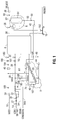
- FIG. 1 is a schematic view of an exemplary system layout of sulfur seed generating spray nozzles with a cooling tank having a screw conveyor disposed with a sulfur granulating system, including a granulating drum, and a wet scrubber with cyclone, an air fan, a belt conveyor, and air, liquid sulfur, and water lines.
- a sulfur granulating system including a granulating drum, and a wet scrubber with cyclone, an air fan, a belt conveyor, and air, liquid sulfur, and water lines.
- FIG. 2A is an isometric view of a sulfur seed generating system with a plurality of sulfur seed generating nozzles positioned with two sulfur seed header conduits, a spiral dewatering cooling tank with its top cover removed, and an internal screw conveyor.
- FIG. 2B is a plan view of FIG. 2A .
- FIG. 2C is an end view of FIG. 2A .
- FIG. 2D is an elevational view of FIG. 2A .
- FIG. 2E is an isometric view of ten sulfur seed generating nozzles attached with hoses to two sulfur seed header conduits.
- FIG. 2F is a detail view of a sulfur seed nozzle of FIG. 2E .
- FIG. 3A is an isometric view of a sulfur seed generating system disposed with a granulating drum system.
- FIG. 3B is a plan view of FIG. 3A .
- FIG. 3C is an end view of FIG. 3A .
- FIG. 3D is an elevational view of FIG. 3A .
- FIG. 4A is an isometric view of a portion of the inside of a granulating drum having a plurality of sets of segmented lifting flights, some of which are not aligned, and rib members attached between the inside surface of the drum and the flights.
- FIG. 4B is similar to FIG. 4A but with one set of segmented lifting flights adjacent to the retaining ring at one end of the drum.
- FIG. 4C is a detail view of a portion of the lifting flights and rib members in FIG. 4B .
- FIG. 4D is an isometric detail view of three sets of rib members, with each rib member set supporting a set of three lifting flights, and one set of lifting flights parallel with the drum rotational axis and two of the three sets of lifting flight not parallel with the drum rotational axis.
- FIG. 5 is a schematic cross-sectional detail view through a granulating drum of the gap between the lifting flights and the drum created by the rib members allowing for more of the finer grained particles to get needed enlargement from the sulfur spray nozzle and more of the coarser grained particles to move through the gap and avoid enlarging sulfur spray.
- FIG. 6 is an isometric view of a portion of the inside of a granulating drum having a plurality of sets of segmented lifting flights some of which are not aligned, rib members attached between the inside surface of the drum and the flights, a liquid sulfur header line (nozzles not shown), and a water header line with a plurality of water nozzles.
- FIG. 7 is a schematic partial cut away section elevational view of an alternative embodiment seed input end of a granulating drum having no lifting flights in that segment of the drum and a membrane attached with membrane attachment strips to the inside surface of the drum adjacent the retaining ring.
- FIG. 7A is a cross-sectional view of the drum of FIG. 7 showing the membrane attached with the drum interior surface with the attachment strips and sulfur seeds falling into a seed bed.
- a sulfur seed generating system 5 comprises sulfur seed generating nozzles 2 (shown in detail in FIGS. 2E and 2F ) and a cooling or a forming tank 4 .
- the cooling tank 4 may be a spiral dewaterer tank with an angled bottom surface and a screw conveyor or auger 20 , as shown in FIGS. 2A to 2D .
- Other cooling tank configurations are also contemplated.
- liquid sulfur is pumped through a liquid sulfur supply line 14 with a liquid sulfur pump 22 .
- the liquid sulfur may be diverted from the line 14 to a seed sulfur line 26 for delivery to tank 4 through sulfur seed nozzles 2 in spray (or droplet) form.
- the cooling tank 4 contains a liquid, such as water, to cool and solidify the molten sulfur spray. Other liquids, fluids or coolants are contemplated. Sulfur seeds formed by the interaction of the sulfur spray with the liquid settle in the tank 4 .
- the sulfur seeds produced by the system 5 may be spherical in shape, typically between 0.1 and 2 mm in diameter and require further enlargement to satisfy SUDIC size specifications in order to obtain maximum commercial value.
- Seeds produced in tank 4 may be transported to a granulating drum 6 by a screw conveyor or auger 20 or other transport means, such as a conveyor belt or a drag chain.
- the auger 20 may extend above the level of the cooling medium in tank 4 to allow entrained cooling medium to drain back to the tank 4 . Dewatering of the seeds may minimize the potential for seeds to agglomerate together in the drum 6 .
- the sulfur line 14 provides sulfur to the drum 6 for enlarging the sulfur seeds into granules.
- An air line 16 provides air to the drum 6 , where the air may be drawn first through cooling tank cover 76 , positioned above tank 4 , so as to collect any vapors that may evolve from the cooling liquid surface.
- a water line 18 connects to water pump 24 and a water filter 40 to provide water to the drum 6 .
- the sulfur supply line 14 may contain measurement devices ( 27 , 28 , 32 ) and an ON/OFF valve 30 .
- the measurement devices, sensors or indicators ( 27 , 28 , 32 ) may measure temperature, pressure, and/or flow rate.
- the measurement device 32 located downstream of the intersection of the sulfur seed line 26 with the supply line 14 may monitor for over-pressure and under-pressure conditions that may cause a system shutdown.
- the single device may be representative of more than one device, such as separate devices to measure temperature, pressure, flow rate, and/or other conditions.
- the output of all measurement devices shown in FIG. 1 may be interrogated by a control system, such as a computer, processor, control logic or microprocessor (not shown).
- the control system may display the measured value, modulate the process control valves and pumps, start up the system, and shut down the system.
- the sulfur supply line 14 and the sulfur seed line 26 may be steam jacketed to keep the liquid sulfur in the liquid state for transmission. Steam may be supplied to the jackets by steam line 34 . Condensate produced as a result of heat transfer from the steam may be passed to condensate line 34 A via steam trap 34 B of conventional design.
- the sulfur pump 22 insures that seed generating nozzles 2 , which are disposed with the tank 4 and therefore outside of the drum 6 , and sulfur granule enlargement nozzles (not shown) inside of the drum 6 , are supplied with the needed sulfur flow rate.
- the sulfur pump 22 may be a positive displacement gear type pump typically equipped with a temperature sensor and a pressure safety valve. Other types of pumps are also contemplated.
- the sulfur flow rate to the drum may be measured by a measuring device 28 , and the flow rate in the seed line 26 may be the difference between the flow rate measured by the device 27 and the flow rate measured by the device 28 .
- the liquid sulfur flow rate to the drum may be controlled by varying the speed of the sulfur pump motor using a variable-frequency drive (VFD). The speed may be set by the control system in accordance with a flow rate provided by flow measuring device 27 .
- VFD variable-frequency drive
- the liquid sulfur pressure in sulfur supply line 14 may be sufficient so that a pressure boost by the sulfur pump 22 is not necessary.
- the pump 22 may be bypassed with a loop and the pump 22 turned off by the control system if the sulfur flow rate is met but the sulfur pump motor amperes remain below a set value for a given period of time.
- the sulfur flow rate in the seed line 26 may be controlled by a flow control valve 180 in the seed line 26
- the flow rate to the drum 6 may be controlled by a flow control valve 181 in the supply line 14 downstream of the intersection with the seed line 26 .
- the control system may turn the pump 22 to the ON condition if the sulfur flow rate remains below one or more pre-determined set points for a given period of time. With the pump ON, the control of the sulfur flow rate to the seed nozzles 2 outside the drum 6 and granule nozzles inside the drum 6 is affected by the sulfur pump VFD.
- the granulating drum 6 enlarges seeds received from the cooling tank 4 to granules by building up the seed diameters with numerous coats of solidified liquid sulfur.
- the drum 6 may be sloped at an angle such that the elevation of the discharge end is lower than the inlet end. The slope angle may be from 0 to 5 degrees, although other angles are also contemplated.
- the flow, temperature, and pressure of the liquid sulfur to the drum 6 may be monitored and controlled. Sulfur pressure may serve as a diagnostic tool. Liquid sulfur temperature and sulfur granule temperature may assist the control system to determine the required cooling water flow rate to the drum 6 and the corresponding volume of effluent expelled by an exhaust fan 36 .
- the drum 6 may be rotated with a VFD motor so as to allow the operator to vary the rotational speed of the drum.
- Drum torque values may be provided by motor ampere readings to inform the operator of any significant change in load.
- the drum 6 may be instrumented with a speed switch, which shuts down the system in the event that drum 6 stops rotating.
- a belt conveyor 10 transports the finished granules to downstream storage and handling facilities.
- the conveyor 10 may be equipped with one or more measurement devices, including a motion detector, misalignment detector, and a manual pull cord.
- the system may be shut down based upon signals from any of the belt conveyor measurement devices.
- the temperature of the sulfur granules on the conveyor 10 may be monitored with a measurement device 182 , which may be an Infrared (IR) instrument.
- Granule temperature may be received in the control system to control the flow rates of water to the drum 6 and effluent extracted by the fan 36 .
- Water supply line 18 supplies cooling water to the drum 6 . Water delivered to the drum 6 is sprayed through water nozzles to effect the required cooling by evaporation.
- a seed water line 38 diverts from the supply line 18 and supplies make-up water to the cooling tank 4 .
- the water pump 24 may be a multi-stage centrifugal pump capable of high discharge pressure.
- a recycle loop with a pressure safety valve from the pump discharge to pump suction may be utilized to protect the line 18 from overpressure. Other types of pumps are also contemplated.
- a flow measurement device 183 on the pump discharge side may provide the system's water requirements. Measurement devices ( 184 , 185 ) in the line 18 may be used to measure pressure, temperature, and/or flow rate, for monitoring and control purposes.
- Make-up water to the tank 4 through the water line 38 may be needed to compensate for evaporation of warmed process water in a wet scrubber 8 and water exported to the drum 6 with the seeds.
- Make-up water may be modulated by control valve 180 A in line 38 in response to the water level measured by a level measurement device 187 in the pump section of the cooling tank 4 .
- a measurement device 188 may be located in the line 26 to monitor pressure and temperature for diagnostic and/or control purposes.
- the required water flow to the drum 6 may be determined from several inputs and compared to the flow measured by a measurement device 183 on the discharge side of the water pump 24 in the water supply line 18 .
- the output of measurement device 183 may be used by the control system to control the position of flow valve 186 in the water supply line 18 , confirm water flow into the drum 6 , and as permissive to start the drum 6 .
- the water flow rate to the drum 6 may be closely estimated in relationship to the heat released by the sulfur solidification process.
- the computed water flow rate may be subject to error since the water introduced into the drum 6 as entrained moisture in the seed stream may not be measured. In this case, the flow valve in the line 18 may be manually trimmed if needed.
- Air supplied through the air supply line 16 is drawn into the drum 6 and becomes progressively hotter and more humid as it migrates through the drum as a result of heat transfer from granules to water spray which results in the production of water vapor.
- the wet scrubber 8 of conventional design and operation captures and removes sulfur dust and sulfur mist present in the drum effluent moving out of the drum in the drum effluent line 58 .
- Process water in the cooling tank 4 flowing over a cooling tank weir 46 may be pumped through the wet scrubber line 12 with a wet scrubber supply pump 44 to the wet scrubber 8 .
- a measurement device 48 in the line 12 may provide temperature, pressure, and/or flow rate measurements.
- the process water with sulfur dust particles collected in cyclone 64 of wet scrubber 8 flows through a line 52 to a cooling tank supply pump 42 , which pumps the slurry back to the cooling tank 4 where the dust particles become entrained in seed sulfur droplets.
- the sulfur dust in the cooling tank may be captured by contact with molten sulfur droplets streaming down the cooling liquid column such that the dust particles become incorporated into the droplet, thereby being converted to a substantially spherical seed. It is also contemplated that the dust particles may be settled out in some other tank or system.
- the balance between water to and from the wet scrubber 8 may be maintained by controlling the water level at the bottom of the cyclone 64 .
- a measurement device 50 in a cyclone slurry output line 52 may monitor water level.
- the water level may be maintained by VFD control of the pump 42 motor speed.
- a measurement device 54 in the line 52 on the discharge side of the pump 42 may measure temperature and pressure. It is anticipated that all of the heat transferred to the fluid in tank 4 as a result of seed generation may be rejected by evaporation in the wet scrubber such that the temperature of the fluid in the line 52 may be cooler than the temperature of the fluid in the line 12 .
- the line 52 may include a heat exchanger (not shown) to further cool the fluid returning to the tank 4 . Heat absorbed by the heat exchanger may be rejected using a suitable cooling device such as a cooling tower or aerial cooler.
- a measurement device 56 in the drum effluent line 58 to the wet scrubber 8 may measure temperature.
- a measurement device 60 in a cyclone air output line 62 connected with the fan 36 may measure temperature.
- the differential pressure across the wet scrubber 8 may also be measured.
- the fan 36 moves air through the system at a flow rate controlled by a VFD on the fan motor.
- the fan 36 may be protected by a vibration switch.
- the effluent flow rate required to maintain a desired sulfur product temperature may depend on several parameters, including ambient dry bulb temperature, ambient humidity, liquid sulfur temperature, liquid sulfur flow rate, sulfur product temperature, water flow rate and temperature, and drum effluent temperature and humidity.
- the humidity of the drum effluent may be derived from the several inputs because direct measurement may be unreliable at high temperature and humidity conditions.
- the fan 36 VFD may be manually trimmed to accommodate any uncertainty in the determined humidity.
- the cooling tank 4 is a spiral dewaterer tank with a screw conveyor or auger 20 .
- Spiral dewaterer tanks are available from Metso Corporation of Helsinki, Finland, among others.
- the tank 4 is disposed on tank support structure or skid 80 A for ease of transportation to a different location and set up for quick operation.
- the tank 4 is filled with a cooling liquid 72 , such as water. Other liquids, fluids and coolants are contemplated.
- the liquid 72 temperature may be 65° C. to 75° C., or approximately 70° C., although other temperatures are also contemplated.
- the height of weir 46 in the tank 4 may be adjusted to change the depth of the water column for the seed droplets to solidify in the tank. It is contemplated that water will overflow the weir 46 since the water may be continuously circulated.
- First and second sulfur seed header conduits ( 70 A, 70 B) disposed with the tank 4 are in fluid communication with sulfur seed spraying nozzles 2 , and are shown in detail in FIGS. 2E and 2F .
- the tank 4 may be deep enough so that sulfur seed droplets may be solidified by the time the droplets reach the floor of the tank.
- the tank depth may be 96 inches (2.4 m) at the deep end and 31 inches (0.8 m) at the shallow end; the tank width may be 78 inches (2 m) at the wide end and 24 inches (0.6 m) at the narrow end, although other depths and widths are also contemplated.
- the cyclone slurry output line 52 shown in FIG. 1 transports a water and sulfur particle mixture from the drum 6 and the wet scrubber 8 into the tank 4 as shown in FIGS. 2A , 2 B and 2 D.
- the tank 4 may be used both to generate seeds from sulfur delivered by the nozzles 2 and to remove sulfur dust received from the line 52 in the manner described above with FIG. 1 . It is also contemplated that the sulfur dust removal process and the seed generation process may be separated.
- the liquid flow in the tank 4 is generally from the right side to the left side as the tank is viewed in FIGS. 2A and 2D .
- the sulfur seed nozzles 2 are attached in fluid communication with a first sulfur seed header conduit 70 A and a second sulfur seed header conduit 70 B.
- the sulfur seed supply line 26 from FIG. 1 is shown for connection with the second header conduit 70 B.
- ten sulfur seed nozzles 2 are attached with the first header 70 A and the second header 70 B with ten sulfur seed tubings or hoses 74 .
- the tubing 74 may be insulated.
- Other attachment means are also contemplated, including attaching the nozzles 2 directly with the header conduits ( 70 A, 70 B).
- a header input conduit 71 may be in fluid communication with the sulfur seed supply line 26 of FIG. 1 .
- the nozzles 2 may be aimed or disposed at a certain angle from horizontal toward the liquid 72 in the tank 4 , such as 45° down from horizontal, although other angles are also contemplated.
- the nozzles 2 may be rotated to different angles.
- the nozzles 2 may be disposed at a certain distance from the liquid 72 in the tank 4 .
- the distance may be 12 inches (30.5 cm), although other distances are also contemplated.
- the nozzles may be spaced approximately 12.4 inches (314 mm) apart, although other spacing is also contemplated.
- the nozzles 2 may be conventional fluid spray nozzles such as are available from Spraying Systems Company of Carol Stream, Ill., among others.
- the orifice size and spray angle of the nozzles 2 may be selected/configured for optimum seed production. It is contemplated that the equivalent diameter of the orifice may be 4.4 mm, although other equivalent orifice diameters are contemplated, such as from 1.4 to 5.8 mm. It is contemplated that the spray angle may be 65°, although other angles are contemplated from 25° to 90°.
- the contemplated nozzle 2 may correspond with a 6550 flat fan nozzle available from Spraying Systems Company, although other types and manufacturers are also contemplated.
- the sulfur pressure under which nozzle 2 operates will vary in accordance with the number, type, and size of nozzles 2 that are required to realize the required flow rate. A spray pressure from 5 psi to 200 psi is contemplated.
- the nozzles 2 may be selected with a flat fan spray (tapered, even, and/or deflected), a conical spray including hollow cone and/or full cone, and/or a deflected spray, although other spray types are also contemplated. Different spray tips may be installed to change the spray pattern and droplet size distribution. It is also contemplated that the nozzles 2 attached with the headers ( 70 A, 70 B) may each have different orifices, spray angles, angles aimed from horizontal, and/or other characteristics. Although ten sulfur seed nozzles 2 are shown in FIG. 2E , it is contemplated that other numbers of the nozzles 2 may be used, such as from four to sixteen nozzles 2 .
- the pressure and/or flow rate of the sulfur moving through the sulfur seed nozzles may be adjusted by the control system to increase or decrease the particle size and amount of sulfur seeds produced.
- the nozzle orifice size, spray angle, and/or other characteristics may also be selected to change the seed size and production rate.
- each seed nozzle may have a flat fan pattern with a 65° spray angle, a 4.4 mm equivalent orifice, and 45 psi liquid sulfur pressure. Other configurations, pressures and sizes are also contemplated.
- a model 6550 nozzle from Spraying Systems Company gives a contemplated spray angle and size.
- seeds produced with a 6550 flat fan nozzle oriented at 45° downward from horizontal and liquid sulfur pressure of 15 psi may produce about 97.7% of seeds by weight that are smaller than 2.36 mm, and about 98.4% of seeds by weight that are larger than 0.3 mm, so that 96% of the seeds may be between 2.36 and 0.3 mm. It is contemplated that at 45 psi liquid sulfur pressure, the size distribution may shift to 98% of seeds by weight less than 2.0 mm and 98% of seeds by weight larger than 0.15 mm, so that 96% of seeds may be between 2.0 and 0.15 mm. Other distributions and sizes are also contemplated.
- the sulfur nozzles used to enlarge seed in the drum may produce a flat spray pattern having a tapered or even edge.
- a plurality of sulfur nozzles may be used on a spray header or manifold such that the spray pattern of adjacent nozzles may overlap in order to provide uniform coverage across the falling curtains in the axial direction.
- the spray pattern may have spray angles from 15° to 110°.
- a nozzle producing a flat even spray pattern may provide a uniform spatial density of droplets throughout the entire flat spay pattern. It may have spray angles from 15° to 110°.
- the thin rectangular spray pattern may provide uniform coverage with minimal overlap between adjacent nozzles.
- a flat even spray pattern may be produced by a deflected type nozzle.
- the spray pattern of medium sized drops is formed by liquid flowing from a round orifice over the deflector surface.
- the spray angles may be from 15° to 150°.
- the nozzle may have a large free passage design though the round orifice that reduces clogging.
- the narrow spray angles provide higher impact, while the wide angle versions produce a lower impact.
- the cooling tank 4 is in fluid communication with the granulating drum 6 ; the wet scrubber 8 and the cyclone 64 are in fluid communication with the drum 6 ; and the fan 36 is in fluid communication with the cyclone 64 .
- the tank 4 is disposed on the tank support structure or skid 80 A, drum 6 is disposed on the drum support structure or skid 80 B, and the cyclone 64 and the wet scrubber 8 are disposed on the cyclone support structure or skid 80 C, all for ease of transportation to a different location or quick set up for operation.
- a cooling tank top cover 76 is disposed with the tank 4 so that the sulfur seed nozzles 2 are not visible.
- the screw conveyor 20 may move seeds to the drum 6 having a first plenum or breach 78 A and a second plenum or breach 78 B.
- the drum effluent line 58 in FIG. 1 moves the air, water vapor and sulfur particle mixture to the wet scrubber 8 , which captures and removes the sulfur dust to the fluid exiting the wet scrubber in line 52 .
- the drum 6 may have a diameter of approximately 10 feet (3 m) and a length of approximately 30 feet (9 m), although other sizes are contemplated. Sulfur granules discharged from drum 6 drop onto belt conveyor 10 shown in FIGS. 3A , 3 B and 3 C.
- FIG. 4A the drum 6 is shown without the first plenum 78 A.
- a first retaining ring 82 minimizes spillage from the drum 6 , and another similar second retaining ring may be positioned at the opposite end of the drum 6 .
- the first retaining ring 82 may have a height of five inches (12.7 cm), although other heights are contemplated.
- a first set of lifting flights 88 is disposed with an interior surface 98 of the drum 6 .
- First set rib members ( 84 A, 84 B) may be disposed between the first flights 88 and the drum interior surface 98 .
- the sets of rib members ( 84 A, 84 B) are segmented in that each set is shorter than the circumference of the interior surface of the drum.
- Each rib member ( 84 A, 84 B) may have a curved length equaling approximately 1 ⁇ 4 of the inside circumference of the drum 6 , such as covering 90° of the 360° circumference. However, other lengths are also contemplated.
- the segmentation of the rib members allows for easy assembly, maintenance and transport.
- Each segmented set of rib members may support a plurality of flights 88 , such as from 1 to 20, with 14 being the preferred amount.
- the rib member 84 A may be attached with the drum 6 at least at two locations, such as at a first connection point 85 A and a second connection point 85 B. As shown in FIG. 4A , the rib member 84 A is preferably attached with drum 6 at four locations: first connection point 85 A, second connection point 85 B, third connection point 85 C, and a fourth connection point (hidden from view by flight 88 A).
- each connection point such as first connection point 85 A and second connection point 85 B, may have a bolt welded to the interior surface of drum 6 extending radially into the drum 6 and passing through a hole in the rib member ( 84 A, 84 B).
- a nut may be used to secure the rib member ( 84 A, 84 B) with the drum at each connection point ( 85 A, 85 B).
- FIGS. 4B and 4C show the connection points of the rib members with the drum interior surface.
- FIG. 4B is similar to FIG. 4A except that first flights 88 of a drum 6 A are positioned with one end adjacent to a first retaining ring 82 A.
- the retaining rings ( 82 , 82 A) may have heights at least as large as the heights of the flights ( 88 , 90 , 92 , 94 , 96 ).
- a rib member 84 A in FIG. 4B is connected with the interior surface of the drum 6 A at a first connection point (hidden from view behind flight 88 B), a second connection point 85 B, a third connection point 85 C, and a fourth connection point 85 D. As shown in FIG.
- the second connection point 85 B of rib member 84 A has two holes 85 B 1 and two holes 85 B 2 .
- Bolts (not shown) are centered on reference line 87 through holes 85 B 2 .
- Bolts (not shown) are also positioned through the two holes 93 B in the rib member 84 B and the two holes 95 A in a rib member 86 A along a reference line 87 .
- the first set of lifting flights 88 is not in alignment with the second set of lifting flights 90 .
- the two holes 95 B in the rib member 86 A allow for alignment of the first set of lifting flights 88 with the second set of lifting flights 90 by moving rib member 86 A so that holes 95 B are positioned along the reference line 87 and bolts are positioned through the holes 95 B rather than the holes 95 A.
- a third connection point 85 C of rib member 84 A has two holes 85 C 1 and two holes 85 C 2 .
- Bolts (not shown) are centered on reference line 89 through holes 85 C 2 .
- Bolts (not shown) are also positioned through the two holes 83 B in rib member 84 B and the two holes 91 A in rib member 86 A along reference line 89 .
- the two holes 91 B in rib member 86 A allow for alignment of the first set of lifting flights 88 with the second set of lifting flights 90 by moving rib member 86 A so that holes 91 B are positioned along reference line 89 and bolts are positioned through holes 91 B rather than holes 91 A. All other rib members and flights may be similarly disposed with the drum 6 .
- each rib member ( 84 A, 84 B, 86 A) may have two pairs of holes at each connection point, such as two holes 85 B 1 and two holes 85 B 2 at second connection point 85 B of rib member 84 A, to allow for the staggering of adjacent flight segments.
- the rib members may have a pair of matching holes spaced apart by half the distance between adjacent flights of a flight segment.
- a staggered configuration may be effected by attaching the ribs to the bolts on the drum wall using alternating hole pairs, e.g. the top pair for the first set of flights, the bottom pair for the second set of flights, the top pair for the third set of flights, and so on.
- a non-staggered alignment may be obtained by aligning the top pair (or bottom pair) of holes in all the flight segments with the bolts. There may be more than one bolt and nut used at each connection point, such as connection points 85 A and 85 B. Other connections are also contemplated.
- flights 88 may be welded to the rib members ( 84 A, 84 B), although other connections are also contemplated. It is also contemplated that there may be no rib members ( 84 A, 84 B), and that the first flights 88 may be attached directly with the interior surface 98 of the drum 6 . As can now be understood, the rib members ( 84 A, 84 B) allow for ease in handling and/or replacement of the first flights 88 . As shown with FIG. 5 and discussed therewith in detail below, the thickness of rib members ( 84 A, 84 B) advantageously provides a gap between the first flights 88 and the surface 98 through which larger seeds and/or granules may move as the drum 6 rotates.
- a second set of lifting flights 90 is also disposed with the interior surface 98 of the drum 6 .
- Second set rib members ( 86 A, 86 B) may be disposed between the second flights 90 and the drum 6 in a similar configuration as the first set rib members ( 84 A, 84 B). It is also contemplated that there may be no rib members ( 86 A, 86 B), and that second flights 90 may be attached directly with the interior surface 98 of the drum 6 .
- a third set of flights 92 , a fourth set of flights 94 , and a fifth set of flights 96 are also shown attached with respective rib members in a similar manner.
- the flights ( 88 , 90 , 92 , 94 , 96 ) are not continuous through the length of the drum 6 but are segmented as they are all shorter than the length of the drum 6 .
- the flights ( 88 , 90 , 92 , 94 , 96 ) may be 4 feet (1.216 m) in length, although other lengths are also contemplated.
- the flights ( 88 , 90 , 92 , 94 , 96 ) are not aligned, but are offset from each other. It is also contemplated that one or more sets of flights ( 88 , 90 , 92 , 94 , 96 ) may be aligned, such as the first flights 88 , the third flights 92 , and all other odd number of flights.
- the even numbers of sets of flights may also be in alignment.
- the sets of rib members such as the first rib members ( 84 A, 84 B) and the second rib members ( 86 A, 86 B)
- the non-aligned or staggered flights may advantageously increase air circulation and cooling in the drum.
- the flights ( 88 , 90 , 92 , 94 , 96 ) are disposed with the drum interior surface 98 on lines parallel with the longitudinal or rotational axis of the drum 6 , such as the first flight 88 attached with the first rib members ( 84 A, 84 B) at respective locations ( 104 A, 104 B). It is also contemplated that one or more sets of flights ( 88 , 90 , 92 , 94 , 96 ) may be disposed with the drum interior surface 98 on lines not parallel with the longitudinal axis of the drum 6 , such as shown in FIG. 4D .
- first set of rib members ( 206 A, 206 B), second set of rib members ( 208 A, 208 B), and third set of rib members ( 210 A, 210 B) are attached with an interior surface 212 of a granulation enlargement drum, such as drum 6 .
- First set of flights 222 are attached with first set of rib members ( 206 A, 206 B)
- second set of flights 224 are attached with second set of rib members ( 208 A, 208 B)
- third set of flights 226 are attached with third set of rib members ( 210 A, 210 B). Only three sets of rib members and flights are shown in FIG. 4D for clarity, although more sets of rib members and flights are contemplated.
- first flights 222 are positioned closest toward the input end of the drum
- third flights 226 are positioned closest to the output end of the drum.
- Reference lines ( 200 A, 200 B, 200 C) are shown for illustrative purposes and are parallel with the drum rotational axis.
- First set of flights 222 are attached with first set of rib members ( 206 A, 206 B) on lines coincident with or parallel to reference lines ( 200 A, 200 B, 200 C).
- Second set of flights 224 are attached with second set of rib members ( 208 A, 208 B) on lines not parallel with reference lines ( 200 A, 200 B, 200 C).
- second flight 224 A with second flight centerline 216 for illustrative purposes, second flight centerline 216 is disposed at angle 214 from reference line 200 B.
- the other second flights 224 may be disposed at angle 214 from their nearest reference line ( 200 A, 200 B, 200 C).
- third set of flights 226 are attached with third set of rib members ( 210 A, 210 B) on lines not parallel with reference lines ( 200 A, 200 B, 200 C).
- third flight centerline 218 is disposed at angle 220 from reference line 200 B. It is contemplated that angle 220 may be greater than angle 214 .
- a lifting flight may be disposed in a plane that only intersects the drum axis at one location.
- the angled flight attachment lines may allow for progressively faster movement of the particles from the input end of the drum 6 to the output end utilizing a screw type action.
- the angled flight attachment lines may change the distance that sulfur granules advance down the drum for each drum rotation. It is contemplated that the angle of attachment may get progressively larger from the input end to the output end of the drum 6 . This may maintain a constant height of the granule bed in the drum in the axial direction, without which the depth of seeds and granules in the bed at the bottom of the drum sometimes may significantly exceed the height of the flights. This condition prevents the flights from lifting the majority of the seeds and granules into the airspace where they may be effectively cooled.
- the angled or screwed flights may advantageously increase the exposure of hot seeds and granules to the cooling atmosphere by minimizing the height of the bed of seeds and granules in the drum.
- the cooler product tends to be less friable and less susceptible to “caking” or “agglomerating” in storage.
- the spiral flights move more granule volume as more volume is produced. This keeps the bed depth at a constant height (slightly above the flights) all the way down the drum. The result is that virtually all granules are kept in circulation to the curtains where they are effectively cooled. Without volumetric acceleration, the extra volume may simply increase the bed depth so more of the bed simply tumbles without being lifted, making cooling less effective.
- first flights 88 may be the same as or different from height 102 of second flights 90 or any other of the flights. It is contemplated that the flights ( 88 , 90 , 92 , 94 , 96 ) may be 5 inches (12.7 cm) in height, although other heights are also contemplated. It is also contemplated that one or more of the flight sets may have angled heights so that their height is not constant across the length of the flights. The angled flights may allow progressively larger volume of particles to be lifted into the airspace from the input end of the drum 6 to the output end. As the bulk volume of granules increases in the axial direction, the deeper flights volume is lifted into the airspace at that particular point where it can be cooled.
- angles may get progressively larger from the input end to the output end of the drum. It is also contemplated that a flight may not be contained in a single plane, such as being curved or bent. It is contemplated that all of the described embodiments of the flights and rib members may be used in any combination or permutation. By varying the configuration of the flights, it is possible to maintain a level amount of sulfur granules along the bottom of the drum 6 as the drum 6 rotates.
- the lifting flights ( 99 , 99 A, 99 B, 99 C, 99 D) are spaced apart from the drum 6 by the thickness of rib members (not shown), providing a gap 132 between the flights ( 99 , 99 A, 99 B, 99 C, 99 D) and the drum 6 interior surface.
- the rib thickness may be in a range from 1 ⁇ 4 inch (0.64 cm) to 2 inches (5.1 cm), although other thicknesses and gaps 132 are also contemplated.
- the flights ( 99 , 99 A, 99 B, 99 C, 99 D) elevate seeds and granules from a bed 134 .
- the flight 99 C may have coarse grains 148 fall though the gap 132 as the flight 99 C begins to discharge so that a majority of coarse grains 148 may not be exposed to a sulfur spray 142 from a spray nozzle 140 attached with a sulfur header conduit 138 in the drum 6 .
- This is advantageous because it allows for more efficient enlargement of the smaller particles, which need more enlargement than the larger particles.
- Finer grained particles 150 from the flight 99 D may discharge into falling curtains 136 toward the sulfur spray nozzle 140 and are the most likely to be sprayed. Fine particles such as a particle 152 may be in the falling curtain 136 closest to the spray nozzle 140 .
- the falling curtain 136 closest to the nozzle 140 may consist mostly of small grains.
- a drum sulfur header line 120 and a drum water line 116 are disposed in the interior of the granulating drum 6 B.
- the sulfur supply line 14 from FIG. 1 may be in fluid communication with the drum sulfur header line 120
- the water supply line 18 from FIG. 1 may be in fluid communication with the drum water line 116 .
- the drum sulfur line 120 has a plurality of sulfur spray nozzles for spraying and enlarging sulfur seeds that are not shown.
- the spray nozzles may be spaced approximately 8 inches (20 cm) apart, although other spacing is also contemplated. It is contemplated that the drum sulfur spray nozzles may be aimed substantially horizontally, although other angles are also contemplated.
- the drum sulfur line 120 may have the capability to rotate to allow spray to be directed downward, upward, or horizontally into the falling curtains. This in particular facilitates the use of a deflected spray sulfur nozzle.
- the drum sulfur line 120 may be steam jacketed.
- the drum sulfur line 120 may be disposed approximately 1 foot (30.5 cm) from the nearest location of the drum 6 B interior surface, although other positions are also contemplated.
- the drum sulfur line 120 may be 30 feet (9.1 m) long inside the 30 foot long drum 6 B with additional one foot extensions outside of the drum at both ends to attach to a supporting structure. Other dimensions are also contemplated.
- the drum water line has a plurality of water spray nozzles 118 . It is contemplated that the water nozzles 118 may be angled downward, such as 45° from horizontal, although other angles are also contemplated. Similar to FIGS. 4A and 4C , exemplary sets of flights 122 and rib members ( 110 A, 110 B) are shown, with the flights 122 having lengths 126 and heights 124 , and a rib member 110 A attached with the drum 6 B at a first connection point 112 A, a second connection point 112 B, a third connection point 112 C, and a fourth connection point 112 D.
- Flights 162 may begin at a distance 164 from the seed input end 176 of the drum 160 , so that there may be no flights in distance 164 .
- the distance 164 may be approximately two feet (0.6 m) to four feet (1.2 m), although other distances are also contemplated.
- a retaining ring 166 may be at a drum end 176 .
- a membrane 170 may be attached to the interior surface of drum 160 in the distance 164 with membrane attachment strips 168 .
- the membrane 170 may be a flexible silicone based membrane, although other types of materials for the membrane 170 are also contemplated.
- the membrane attachment strips may be conventional dimensional steel such as channel stock. It is contemplated that wet seeds may enter the drum end 176 and be in a tumbling seed bed 172 , in which seeds may be held together by moisture. As the drum 160 rotates, dislodged seed clumps may fall, such as in curtains 174 , to the bed 172 . As can now be understood, the membrane 170 allows for seeds that may have a tendency to clump from moisture to potentially be separated and dried before being elevated by lifting flights 162 . Normal airflow without water spray through this zone may dry out the seeds before entering the normal flighted section of the drum 160 .
- the embodiments described above may allow control of the size distribution and production rate of seeds, produced outside the granulating drum, that enable a one pass enlargement cycle through the drum (no seed recycle) at a high production rate (1500 tonne per day or more).
- This capability may eliminate the need for an output screen and underside recycle conveyor (lower capex and opex).
- the system may provide for an increase in unit production rate and improved product quality enabled by improved cooling of granules (i.e. enhanced exposure of granules to the sweep air that itself is kept cool by water evaporation). This may be achieved by non-aligned or staggered lifting flights. This may provide for a more tortuous path for airflow around the falling curtains.
- a drum revolutions per minute may be selected such that the falling curtains fill approximately 75% or more of the granulating drum volume. Flights attached with rib members or attached directly to the drum on lines not parallel with the drum rotational axis provide for a “screwed flights” design to move the bed to the discharge end at a progressively faster rate, corresponding to sulfur mass introduced as spray, so that the amount of granules tumbling in the bed and not being cooled may be kept to a minimum.
- a substantially constant product temperature may be maintained in respect to changes in key operating variables, such as sulfur production rate, the temperature of the liquid sulfur and the sulfur product, and ambient temperature and humidity, among others. This may be achieved by adjusting the airflow rate through the drum by varying the speed of the fan. The fan speed may be determined by the control system or processor using inputs from the various instruments.
- the system shown schematically in FIG. 1 may be disposed on support structures or skids for ease of construction or transportation, such as support structures ( 80 A, 80 B, 80 C) in FIGS. 2A-2D , 3 A- 3 D, and 4 A- 4 B.
- the system may substantially eliminate the conveyors and other structures of the prior art extending from the output end of the drum to the input end of the drum that are required for the recycling of undersized sulfur particles back through the drum.
- the modular nature of the system allows for easy set up and operation.
- the production of sulfur seeds externally to the drum 6 may allow for the use of lower pressures in the drum 6 , and better optimization of granule production.
- the separation of the seed production from the granule production also may allow for better optimization of seed production.
- the method and system may be used for sulfur (or sulphur), it is also contemplated that the method and system, and any of the embodiments and components, may be used for converting other molten liquids to solid seeds or granules, such as asphalt.
- the exemplary embodiment of the method and system passes the molten sulfur through water, other fluids or cooling medium besides water, as known in the art, but novel when used herein, are contemplated and may be used.
Landscapes
- Chemical & Material Sciences (AREA)
- Organic Chemistry (AREA)
- Inorganic Chemistry (AREA)
- Chemical Kinetics & Catalysis (AREA)
- Engineering & Computer Science (AREA)
- Mechanical Engineering (AREA)
- Pretreatment Of Seeds And Plants (AREA)
- Fertilizers (AREA)
- Glanulating (AREA)
Abstract
Description
Claims (38)
Priority Applications (10)
| Application Number | Priority Date | Filing Date | Title |
|---|---|---|---|
| US12/953,512 US8329072B2 (en) | 2010-11-24 | 2010-11-24 | Method and system for generating sulfur seeds and granules |
| PCT/US2011/052012 WO2012071104A2 (en) | 2010-11-24 | 2011-09-16 | Method and system for generating sulfur seeds and granules |
| RU2013127154A RU2606982C2 (en) | 2010-11-24 | 2011-09-16 | Method and system for generating sulphur seeds and granules |
| KR1020137015840A KR20130131376A (en) | 2010-11-24 | 2011-09-16 | Method and system for generating sulfur seeds and granules |
| MX2013005909A MX339282B (en) | 2010-11-24 | 2011-09-16 | Method and system for generating sulfur seeds and granules. |
| EP11843884.5A EP2643266A4 (en) | 2010-11-24 | 2011-09-16 | Method and system for generating sulfur seeds and granules |
| CA2806125A CA2806125C (en) | 2010-11-24 | 2011-09-16 | Method and system for generating sulfur seeds and granules |
| US13/363,235 US8425811B2 (en) | 2010-11-24 | 2012-01-31 | Method and system for generating sulfur seeds in a moving liquid |
| US13/709,021 US8691121B2 (en) | 2010-11-24 | 2012-12-09 | Sulfur granulator system and method |
| US14/247,112 US9028729B2 (en) | 2010-11-24 | 2014-04-07 | Sulfur granulator system and method |
Applications Claiming Priority (1)
| Application Number | Priority Date | Filing Date | Title |
|---|---|---|---|
| US12/953,512 US8329072B2 (en) | 2010-11-24 | 2010-11-24 | Method and system for generating sulfur seeds and granules |
Related Child Applications (2)
| Application Number | Title | Priority Date | Filing Date |
|---|---|---|---|
| US13/363,235 Continuation-In-Part US8425811B2 (en) | 2010-11-24 | 2012-01-31 | Method and system for generating sulfur seeds in a moving liquid |
| US13/709,021 Continuation US8691121B2 (en) | 2010-11-24 | 2012-12-09 | Sulfur granulator system and method |
Publications (2)
| Publication Number | Publication Date |
|---|---|
| US20120126439A1 US20120126439A1 (en) | 2012-05-24 |
| US8329072B2 true US8329072B2 (en) | 2012-12-11 |
Family
ID=46063601
Family Applications (3)
| Application Number | Title | Priority Date | Filing Date |
|---|---|---|---|
| US12/953,512 Expired - Fee Related US8329072B2 (en) | 2010-11-24 | 2010-11-24 | Method and system for generating sulfur seeds and granules |
| US13/709,021 Active US8691121B2 (en) | 2010-11-24 | 2012-12-09 | Sulfur granulator system and method |
| US14/247,112 Active US9028729B2 (en) | 2010-11-24 | 2014-04-07 | Sulfur granulator system and method |
Family Applications After (2)
| Application Number | Title | Priority Date | Filing Date |
|---|---|---|---|
| US13/709,021 Active US8691121B2 (en) | 2010-11-24 | 2012-12-09 | Sulfur granulator system and method |
| US14/247,112 Active US9028729B2 (en) | 2010-11-24 | 2014-04-07 | Sulfur granulator system and method |
Country Status (7)
| Country | Link |
|---|---|
| US (3) | US8329072B2 (en) |
| EP (1) | EP2643266A4 (en) |
| KR (1) | KR20130131376A (en) |
| CA (1) | CA2806125C (en) |
| MX (1) | MX339282B (en) |
| RU (1) | RU2606982C2 (en) |
| WO (1) | WO2012071104A2 (en) |
Cited By (3)
| Publication number | Priority date | Publication date | Assignee | Title |
|---|---|---|---|---|
| US20110293763A1 (en) * | 2010-05-26 | 2011-12-01 | Kyu Yeub Yeon | Manufacturing Device of Spherical Magnesium Fine Powder |
| US20140217631A1 (en) * | 2010-11-24 | 2014-08-07 | Leslie L. Lang | Sulfur granulator system and method |
| WO2022198318A1 (en) * | 2021-03-24 | 2022-09-29 | Enersul Inc. | Single pass header for generating sulfur seed particles and enlarging sulfur granules, and method of using the same |
Families Citing this family (13)
| Publication number | Priority date | Publication date | Assignee | Title |
|---|---|---|---|---|
| GB201113007D0 (en) * | 2011-07-28 | 2011-09-14 | Q Chip Ltd | Bead collection device and method |
| CN104289154A (en) * | 2014-10-23 | 2015-01-21 | 南京三普造粒装备有限公司 | Device capable of improving particle uniformity of spherical sulfur or sulfur derivatives and implementation method |
| CN105984853A (en) * | 2015-01-31 | 2016-10-05 | 江苏宏泰橡胶助剂有限公司 | Drying room for producing insoluble sulfur |
| CN105984852A (en) * | 2015-01-31 | 2016-10-05 | 江苏宏泰橡胶助剂有限公司 | Improved drying house for producing insoluble sulfur |
| CN105129740B (en) * | 2015-10-12 | 2017-10-10 | 洛阳涧光特种装备股份有限公司 | A kind of wet-method sulfur forming equipment and its moulding process |
| RU2643556C1 (en) * | 2016-11-15 | 2018-02-02 | Общество с ограниченной ответственностью "Газпром переработка" (ООО "Газпром переработка") | Device for cryogenic granulation of liquid sulphur |
| RU2645134C1 (en) * | 2016-11-15 | 2018-02-15 | Общество с ограниченной ответственностью "Газпром переработка" | Device for granulating liquid sulfur |
| CN106956380B (en) * | 2017-04-06 | 2023-11-21 | 国网冀北电力有限公司廊坊供电公司 | A multi-stage cooling device for polyethylene resin materials for power cables |
| US10967300B2 (en) * | 2017-08-29 | 2021-04-06 | Green Flow Industries, LLC | Transportable separation and monitoring apparatus with auger |
| CN110745785B (en) * | 2019-11-21 | 2023-03-14 | 余智敏 | Wet-process sulfur forming granulation production system and production process |
| IT202000014887A1 (en) * | 2020-06-22 | 2021-12-22 | I E E C Free Port Ltd | APPARATUS FOR SOLIDIFYING LIQUID SULFUR INTO ORTHOHOMBIC CRYSTALS AND RELATED PROCEDURE |
| CN114058895B (en) * | 2021-11-16 | 2023-01-17 | 陕西宝锐金属有限公司 | Double nozzle spray forming Y 2 O 3 Process for particle reinforced Monel 400 alloy plate |
| CN119370804B (en) * | 2024-11-21 | 2025-11-11 | 四川豪诚物流有限公司 | Insoluble sulfur liquid-solid conversion system and application method thereof |
Citations (112)
| Publication number | Priority date | Publication date | Assignee | Title |
|---|---|---|---|---|
| US1378084A (en) * | 1919-10-06 | 1921-05-17 | Texas Gulf Sulphur Co | Refining sulfur |
| US2811748A (en) | 1955-01-25 | 1957-11-05 | Philip A Smith | Manufacture of shot |
| US2923033A (en) | 1954-09-24 | 1960-02-02 | Hercules Powder Co Ltd | Method for pelleting |
| US3060510A (en) | 1961-06-12 | 1962-10-30 | Koppers Co Inc | Process for converting fusible materials, solid at ordinary temperatures, into spherical granules |
| US3210443A (en) | 1962-12-31 | 1965-10-05 | Socony Mobil Oil Co Inc | Preparation of substituted indenes |
| US3334159A (en) | 1964-09-17 | 1967-08-01 | Nat Sulphur Company | Method for prilling sulphur |
| US3348938A (en) | 1963-04-18 | 1967-10-24 | Ici Ltd | Process for producing granular mixed fertilizer |
| US3398458A (en) | 1966-03-25 | 1968-08-27 | Potasse & Engrais Chimiques | Method and means for the introduction of fluids into a rotating container |
| US3446877A (en) | 1967-04-28 | 1969-05-27 | Lummus Co | Process for producing prills |
| US3472922A (en) | 1965-07-08 | 1969-10-14 | Oesterr Studien Atomenergie | Method for the production of spherical particles |
| US3538200A (en) | 1968-12-26 | 1970-11-03 | Shell Oil Co | Method for prilling molten sulfur |
| US3609088A (en) | 1968-10-11 | 1971-09-28 | Stauffer Chemical Co | Method of preparing agglomerated detergent composition |
| US3646689A (en) | 1969-09-17 | 1972-03-07 | Werner & Pfleiderer | Continually operating fluidized bed dryer for drying loose material |
| US3649217A (en) | 1970-05-21 | 1972-03-14 | Allied Chem | Sulfur extraction |
| US3689226A (en) | 1971-03-03 | 1972-09-05 | Allied Chem | Sulfur extraction apparatus |
| US3836611A (en) | 1971-01-08 | 1974-09-17 | I Mavrovic | Process for prilling urea |
| US3877415A (en) | 1973-07-24 | 1975-04-15 | Tennessee Valley Authority | Apparatus for applying coatings to solid particles |
| US3888956A (en) | 1968-02-05 | 1975-06-10 | Uddeholms Ab | Method of making granulate |
| US3903333A (en) | 1973-03-30 | 1975-09-02 | Tennessee Valley Authority | Production of slow release nitrogen fertilizers by improved method of coating urea with sulfur |
| US3933956A (en) | 1972-05-22 | 1976-01-20 | Ivo Mavrovic | Process for prilling urea |
| US3975472A (en) | 1974-02-01 | 1976-08-17 | Stamicarbon B.V. | Process and device for preparing prills |
| US3991225A (en) | 1974-02-01 | 1976-11-09 | Tennessee Valley Authority | Method for applying coatings to solid particles |
| US4031174A (en) | 1973-02-09 | 1977-06-21 | Fisons Limited | Process of prilling molten materials |
| US4043717A (en) | 1976-04-12 | 1977-08-23 | Valley Nitrogen Producers, Inc. | Sulphur granulator |
| US4056340A (en) | 1976-07-01 | 1977-11-01 | The Upjohn Company | Prilling apparatus |
| US4081500A (en) | 1974-10-03 | 1978-03-28 | The Cambrian Engineering Group Limited | Sulphur pelletization process |
| US4082823A (en) | 1975-12-03 | 1978-04-04 | United States Steel Corporation | Process for forming coated pitch prills |
| US4102968A (en) | 1977-07-11 | 1978-07-25 | Arcanum Corporation | Agglomeration of finely divided sulfur particles in a liquid suspension |
| US4133669A (en) | 1977-04-20 | 1979-01-09 | Agri-Prassco Joint Venture | Process for pelletizing a sulphur-bentonite clay mixture and the product formed thereby |
| US4149837A (en) | 1976-03-22 | 1979-04-17 | Ronald Baker | Sulphur pelletizing apparatus |
| US4213924A (en) | 1978-06-19 | 1980-07-22 | Tennessee Valley Authority | Granulation and coating by improved method of heat removal |
| US4234318A (en) | 1977-02-04 | 1980-11-18 | Cominco Ltd. | Process for granulation of sulfur |
| US4254067A (en) | 1975-06-03 | 1981-03-03 | Elliott Herbert J | Sulphur pelletizing |
| US4263012A (en) | 1978-12-01 | 1981-04-21 | Instytut Przemyslu Organicznego | Method of granulation of sulfur |
| US4272234A (en) | 1978-11-06 | 1981-06-09 | Procor Limited | Pelletizing apparatus |
| US4305913A (en) | 1980-08-06 | 1981-12-15 | Kaiser Aluminum & Chemical Corporation | Alumina hydrate production from Bayer liquor by seeding |
| US4353852A (en) | 1978-11-06 | 1982-10-12 | Procor Limited-Procor Limitee | Pelletizing method and apparatus |
| US4364919A (en) | 1981-02-20 | 1982-12-21 | Sumitomo Aluminium Smelting Company, Limited | Process for producing coarse grains of aluminum hydroxide |
| US4370252A (en) | 1979-03-06 | 1983-01-25 | Phillips Petroleum Company | Emulsion polymerization process utilizing a highly dispersed organosulfur molecular weight modifier |
| US4389356A (en) | 1981-07-07 | 1983-06-21 | Cominco Ltd. | Sulfur prilling |
| US4408998A (en) | 1981-06-19 | 1983-10-11 | Unie Van Kunstmestfabrieken Bv | Process for preparing thermally stable ammonium nitrate- containing granules |
| US4424176A (en) | 1982-09-29 | 1984-01-03 | Tennessee Valley Authority | Process for granulation of molten materials |
| US4449900A (en) | 1982-07-01 | 1984-05-22 | Lerner Bernard J | Prilling |
| US4507335A (en) | 1984-02-13 | 1985-03-26 | Procor Limited | Method and apparatus for pelletizing sulphur |
| US4511542A (en) | 1984-05-24 | 1985-04-16 | Kaiser Aluminum & Chemical Corporation | Bayer process production of alumina hydrate |
| US4563315A (en) | 1982-09-27 | 1986-01-07 | Adelaide & Wallaroo Fertilizers Ltd. | Production of particulate solids in rotary fluidizer |
| US4569859A (en) * | 1984-07-10 | 1986-02-11 | Sulpetro Limited | Process for forming prill for sulphur and bentonite |
| US4617179A (en) | 1984-11-22 | 1986-10-14 | Aluminium Pechiney | Process for effecting seeding in two phases for producing large-grain alumina |
| US4842790A (en) * | 1988-02-22 | 1989-06-27 | Tennessee Valley Authority | Method and apparatus for producing high-strength grannular particulates from low-strength prills |
| US4857098A (en) | 1987-08-11 | 1989-08-15 | Pursell Industries | Sulfur-coated fertilizer granules and process of making same |
| US4863645A (en) * | 1987-09-29 | 1989-09-05 | Union Oil Company Of California | Apparatus and process for producing particulate sulfur |
| US4871489A (en) | 1986-10-07 | 1989-10-03 | Corning Incorporated | Spherical particles having narrow size distribution made by ultrasonic vibration |
| US4931231A (en) * | 1985-04-22 | 1990-06-05 | American Colloid Company | Method for manufacturing discrete pellets of asphaltic material |
| US4935173A (en) | 1987-01-20 | 1990-06-19 | The Dow Chemical Company | Process for producing prills |
| US4944769A (en) | 1986-03-21 | 1990-07-31 | Petroleo Brasileiro S.A. - Petrobras | Process for the granulating of sulphur |
| US4966736A (en) * | 1985-12-19 | 1990-10-30 | Union Oil Company Of California | Process for preparing sulfur having uniform particle size distribution |
| US4986941A (en) | 1990-07-02 | 1991-01-22 | Xerox Corporation | Shotting apparatus and process |
| US5006369A (en) | 1988-08-05 | 1991-04-09 | The Dow Chemical Company | Removing contaminants from a gas stream |
| US5030437A (en) | 1987-12-23 | 1991-07-09 | Budra Research Ltd. | Catalytic removal of sulphur-containing compounds from fluid streams by decomposition |
| US5071332A (en) | 1986-03-21 | 1991-12-10 | Petroleo Brasileiro S.A. | Sulphur granulator |
| US5096571A (en) | 1989-12-12 | 1992-03-17 | Freeport Mcmoran Resource Partners, Ltd. Partnership | Recovery of sulfur from native ores |
| US5102586A (en) | 1988-10-27 | 1992-04-07 | Kawasaki Steel Corporation | Agglomerating process of sinter mix and apparatus therefor |
| US5205958A (en) | 1989-06-16 | 1993-04-27 | The Clorox Company | Zeolite agglomeration process and product |
| US5236466A (en) | 1991-08-30 | 1993-08-17 | Chilean Nitrate Corporation | Fast cooling of partially solidified granules of low melting, subliming substances obtained by prilling |
| US5401445A (en) * | 1993-06-25 | 1995-03-28 | Martin Marietta Energy Systems, Inc. | Fluid casting of particle-based articles |
| US5435945A (en) * | 1992-05-29 | 1995-07-25 | Procor Sulphur Services, Inc. | Method and apparatus for generating sulphur seed particles for sulphur granule production |
| US5437691A (en) | 1991-08-30 | 1995-08-01 | Chilean Nitrate Corporation | Production of spherical shaped products of subliming substances |
| US5460765A (en) | 1992-04-30 | 1995-10-24 | Derdall; Gary | Process for pan granulating a particulate material |
| US5514307A (en) | 1992-10-13 | 1996-05-07 | Laroche Industries, Inc. | Process for the reducing emissions during prilling of material such as ammonium nitrate |
| US5558821A (en) | 1993-09-25 | 1996-09-24 | Santrade Ltd. | Method and apparatus for purifying the exhaust air of installations for consolidating molten substances |
| US5571303A (en) | 1995-03-06 | 1996-11-05 | Cominco Fertilizers Ltd. | Sulfur-based fertilizer and process for production thereof |
| US5599374A (en) | 1994-09-23 | 1997-02-04 | Rlc Technologies, L.L.C. | Process for producing improved sulfur-coated urea slow release fertilizers |
| US5628937A (en) | 1992-12-18 | 1997-05-13 | Imperial Chemical Industries Plc | Production of particulate materials |
| US5664422A (en) | 1995-03-29 | 1997-09-09 | Jones; Curt D. | Dropper assembly for liquid feed and method of feeding liquid composition to a freezing chamber |
| US5691297A (en) | 1994-09-20 | 1997-11-25 | The Procter & Gamble Company | Process for making a high density detergent composition by controlling agglomeration within a dispersion index |
| US5766521A (en) | 1995-04-10 | 1998-06-16 | Rhone-Poulenc Chimie | Process for obtaining cristallized pearls exhibiting the phenomenon of supercooling |
| US5770235A (en) | 1994-11-16 | 1998-06-23 | Santrade Ltd. | Drop forming drum for the manufacture of pastilles |
| US5779945A (en) | 1996-04-15 | 1998-07-14 | Dsm N.V. | Process for producing granules |
| US5788896A (en) * | 1997-02-27 | 1998-08-04 | Alberta Research Council | Method of producing micron sized sulphur granules |
| US5975442A (en) | 1998-09-02 | 1999-11-02 | Purser; Brian | Cable granulator |
| US6162377A (en) | 1999-02-23 | 2000-12-19 | Alberta Research Council Inc. | Apparatus and method for the formation of uniform spherical particles |
| US6168733B1 (en) | 1998-08-31 | 2001-01-02 | Eastman Chemical Company | Method for forming discrete pellets from viscous materials |
| US6203730B1 (en) | 1997-09-04 | 2001-03-20 | Toyo Engineering Corporation | Method for granulation and granulator |
| US6331245B1 (en) | 1999-11-23 | 2001-12-18 | Kellogg Brown & Root, Inc. | Petroleum resid pelletization |
| US20020056931A1 (en) | 2000-11-14 | 2002-05-16 | Urea Casale S.A. | Method for obtaining urea prills |
| US20020063351A1 (en) | 2001-03-28 | 2002-05-30 | Ball Semiconductor, Inc. | Jet system for spherical shape devices |
| US6398989B1 (en) | 1998-02-27 | 2002-06-04 | Sandvik Process Systems, Inc. | Drop forming methods and apparatus |
| US20020102310A1 (en) | 1999-12-03 | 2002-08-01 | Avecia, Inc. | Phenothiazine in prill form and method for making the same |
| US6440336B1 (en) | 1997-10-06 | 2002-08-27 | Adalbert-Raps-Stiftung | Method for producing a powder product from a liquid substance or mixture of substances |
| US6499979B2 (en) | 1999-11-23 | 2002-12-31 | Kellogg Brown & Root, Inc. | Prilling head assembly for pelletizer vessel |
| US6579479B1 (en) | 2000-11-09 | 2003-06-17 | Honeywell International Inc. | Methods of forming a plurality of spheres; and pluralities of spheres |
| US20040088830A1 (en) | 2001-01-17 | 2004-05-13 | Mennen Johannes Henricus | Process for the preparation of granules |
| US6749659B1 (en) | 2001-10-09 | 2004-06-15 | Enersul, Inc. | Controlled release rate fertilizers and methods of making same |
| US20040163434A1 (en) | 2001-05-09 | 2004-08-26 | Quin Bertram Francis Charles | Fertiliser compositions |
| US6790418B2 (en) | 1999-04-12 | 2004-09-14 | Phillips Petroleum Company | Materials and method for the biological production of sulfuric acid |
| US20060010708A1 (en) | 2004-07-19 | 2006-01-19 | Earthrenew Organics Ltd. | Control system for gas turbine in material treatment unit |
| US7033556B1 (en) | 2001-11-26 | 2006-04-25 | Squires Arthur M | Method and apparatus for cake-forming granular-bed filtration |
| US7208107B2 (en) | 2000-08-29 | 2007-04-24 | Buhler Ag | Method and device for producing spherical particles from a polymer melt |
| US20080029924A1 (en) | 2006-08-01 | 2008-02-07 | Sharp Kabushiki Kaisha | Method of manufacturing aggregated particles |
| US7343697B2 (en) | 2005-05-31 | 2008-03-18 | Dillman Equipment, Inc. | Low profile flights for use in a drum |
| US20080107902A1 (en) | 2004-09-09 | 2008-05-08 | Optnics Precision Co., Ltd. | Spherical Ultrafine Particles and Process for Producing the Same |
| US7413690B1 (en) | 2003-10-29 | 2008-08-19 | The University Of Mississippi | Process and apparatus for producing spherical pellets using molten solid matrices |
| US20080272508A1 (en) | 2001-12-11 | 2008-11-06 | Buehler Ag | Manufacture of spherical particles out of a plastic melt |
| US20090035579A1 (en) | 2005-04-18 | 2009-02-05 | Ami-Agrolinz Melamine International Gmbh | Solid particles, method and device for the production thereof |
| WO2009054906A1 (en) | 2007-10-26 | 2009-04-30 | Martin Resource Management Corporation | Method and system for pelletizing sulfur |
| WO2009074250A2 (en) | 2007-12-11 | 2009-06-18 | Sandvik Materials Technology Deutschland Gmbh | Method and drop former for producing tablets and method for producing a sulfurous fertilizer |
| US20090215000A1 (en) | 2005-12-05 | 2009-08-27 | Craig Gordon Boots | Method and Apparatus for Processing of Materials |
| WO2009155682A1 (en) | 2008-06-27 | 2009-12-30 | Enersul Inc. | Sulphur granulation apparatus and process |
| WO2010086395A1 (en) | 2009-01-29 | 2010-08-05 | Shell Internationale Research Maatschappij B.V. | Sulphur-containing fertilizers and process for the preparation thereof |
| WO2010090518A2 (en) | 2009-02-03 | 2010-08-12 | Nederlandse Organisatie Voor Toegepast- Natuurwetenschappelijk Onderzoek Tno | Multi component particle generating system |
| US20100233332A1 (en) | 2004-06-14 | 2010-09-16 | Agrium Inc. | Process and apparatus for producing a coated product |
| WO2010107401A2 (en) | 2009-03-19 | 2010-09-23 | Brinox, D.O.O. | Enhanced processing device for coating particles via a new airflow vortex generator method |
Family Cites Families (41)
| Publication number | Priority date | Publication date | Assignee | Title |
|---|---|---|---|---|
| US426489A (en) | 1890-04-29 | Filter | ||
| US1053573A (en) | 1912-05-07 | 1913-02-18 | Nora K Clemm | Kitchen utensil. |
| US1331646A (en) | 1919-12-13 | 1920-02-24 | Hood John James | Purification of sulfur |
| NL32209C (en) | 1930-03-15 | |||
| US2056929A (en) | 1933-05-13 | 1936-10-06 | Brown Co | Production of alkaline compounds, sulphuric acid, and other valuable chemicals |
| US2169261A (en) | 1936-03-24 | 1939-08-15 | Freeport Sulphur Co | Process for purifying sulphur |
| US2429477A (en) | 1941-03-11 | 1947-10-21 | Arthur B Menefee | Recovery of sulphur from sulphur ores |
| US2402553A (en) | 1941-06-10 | 1946-06-25 | Du Pont | Sulphuric acid manufacture and apparatus therefor |
| US2622007A (en) | 1949-03-16 | 1952-12-16 | Chemical Construction Corp | Process for producing sulfur dioxide and sulfur burner |
| US2796325A (en) | 1951-10-24 | 1957-06-18 | Thiokol Chemical Corp | Process of making alkaline sulfides and sulfites |
| US2785059A (en) | 1953-02-26 | 1957-03-12 | American Sulphur & Refining Co | Solvent extraction of sulphur |
| US2847201A (en) | 1954-11-09 | 1958-08-12 | Carroll R Graham | Portable sulphur plant for use in a region of subsidence |
| US2731332A (en) | 1955-01-06 | 1956-01-17 | Ackert George Ford | Process for extraction of sulfur from sulfur ores |
| US2959869A (en) * | 1959-08-27 | 1960-11-15 | Wilbert E Ackerman | Drying mixtures of coarse and fine particles |
| NL131270C (en) | 1964-02-03 | |||
| BR8205991A (en) * | 1982-09-30 | 1984-05-08 | Ultrafertil Sa | SULFUR BORING PROCESS |
| US4518577A (en) | 1982-12-20 | 1985-05-21 | Shell Oil Company | Sulfur separation process |
| US4729887A (en) | 1985-08-16 | 1988-03-08 | Amoco Corporation | Process and apparatus for degassing sulfur |
| US4705676A (en) | 1985-08-23 | 1987-11-10 | Shell Oil Company | Recovery of sulfur from a solid sulfur-containing solution of a solubilized iron chelate |
| DE3606931A1 (en) | 1986-03-04 | 1987-09-10 | Santrade Ltd | METHOD AND DEVICE FOR CLEANING POLLUTED SULFUR |
| US4923482A (en) | 1986-04-15 | 1990-05-08 | Sulexport-Intertrade A.G. | Process for separating sulfur from ore |
| US4730369A (en) | 1986-06-16 | 1988-03-15 | Ari Technologies, Inc. | Method and apparatus for melting and recovering sulfur in aqueous slurries |
| US4722832A (en) | 1986-08-27 | 1988-02-02 | Freeport-Mcmoran Resource Partners | Sulfur recovery process |
| US4995894A (en) | 1989-05-01 | 1991-02-26 | National Slag Limited | Enclosures for slag pelletization apparatus and method of operation |
| US5711929A (en) | 1989-05-06 | 1998-01-27 | 698638 Alberta Ltd. | Purification of elemental sulphur |
| US5049370A (en) | 1989-09-26 | 1991-09-17 | Ultraclean Incorporated | Process and apparatus for purifying elemental sulfur carried in an aqueous cake |
| US5122351A (en) | 1990-12-20 | 1992-06-16 | Ari Technologies Inc. | Method and apparatus for removing H2 S from a process gas and recovering sulfur |
| US5425880A (en) | 1992-08-28 | 1995-06-20 | Rust Industrial Services Inc. | Apparatus and process for treatment of liquids |
| DE4402311C2 (en) | 1993-02-06 | 1998-02-26 | Kronos Titan Gmbh | Process for improving the filtration of sulfur-containing suspensions |
| ATE214350T1 (en) | 1993-09-01 | 2002-03-15 | Apollo Environmental Syst Corp | DEGASING OF LIQUID SULFUR |
| US5651896A (en) | 1995-08-15 | 1997-07-29 | Wheelabrator Clean Air Systems Inc. | Sulfur separation system with interface control |
| NL1003085C2 (en) | 1995-09-15 | 1997-03-20 | Stork Comprimo Bv | Method and device for degassing sulfur. |
| US5772968A (en) | 1996-07-03 | 1998-06-30 | Sunrise, Inc. | Apparatus and method for hydrolyzing keratinaceous material |
| US5938813A (en) * | 1997-01-27 | 1999-08-17 | Sqm Nitratos, S.A. | Granular coated particles containing urea and metal nitrate, and process for making the same |
| US5935548A (en) | 1998-03-11 | 1999-08-10 | Black & Veatch Pritchard, Inc. | Method for removing hydrogen sulfide from molten sulfur |
| US6676918B2 (en) | 2002-06-14 | 2004-01-13 | Exxonmobil Research And Engineering Company | Hydrogen sulfide removal from liquid sulfur |
| US6976819B2 (en) * | 2003-04-16 | 2005-12-20 | Del Corporation | Tank having multiple screw-type transfer augers |
| KR20100042293A (en) | 2007-08-14 | 2010-04-23 | 셀 인터나쵸나아레 레사아치 마아츠샤피 비이부이 | System and methods for continuous, online monitoring of a chemical plant or refinery |
| US7635460B2 (en) | 2007-08-17 | 2009-12-22 | Carrasco Robert M | Process for dissolving sulfur ore using diaryl disulfide |
| US7918994B2 (en) | 2008-03-27 | 2011-04-05 | Brimrock International Inc. | System that removes contaminants from sulfur |
| US8329072B2 (en) * | 2010-11-24 | 2012-12-11 | Brimrock International Inc. | Method and system for generating sulfur seeds and granules |
-
2010
- 2010-11-24 US US12/953,512 patent/US8329072B2/en not_active Expired - Fee Related
-
2011
- 2011-09-16 RU RU2013127154A patent/RU2606982C2/en not_active IP Right Cessation
- 2011-09-16 KR KR1020137015840A patent/KR20130131376A/en not_active Ceased
- 2011-09-16 WO PCT/US2011/052012 patent/WO2012071104A2/en not_active Ceased
- 2011-09-16 MX MX2013005909A patent/MX339282B/en active IP Right Grant
- 2011-09-16 EP EP11843884.5A patent/EP2643266A4/en not_active Withdrawn
- 2011-09-16 CA CA2806125A patent/CA2806125C/en not_active Expired - Fee Related
-
2012
- 2012-12-09 US US13/709,021 patent/US8691121B2/en active Active
-
2014
- 2014-04-07 US US14/247,112 patent/US9028729B2/en active Active
Patent Citations (115)
| Publication number | Priority date | Publication date | Assignee | Title |
|---|---|---|---|---|
| US1378084A (en) * | 1919-10-06 | 1921-05-17 | Texas Gulf Sulphur Co | Refining sulfur |
| US2923033A (en) | 1954-09-24 | 1960-02-02 | Hercules Powder Co Ltd | Method for pelleting |
| US2811748A (en) | 1955-01-25 | 1957-11-05 | Philip A Smith | Manufacture of shot |
| US3060510A (en) | 1961-06-12 | 1962-10-30 | Koppers Co Inc | Process for converting fusible materials, solid at ordinary temperatures, into spherical granules |
| US3210443A (en) | 1962-12-31 | 1965-10-05 | Socony Mobil Oil Co Inc | Preparation of substituted indenes |
| US3348938A (en) | 1963-04-18 | 1967-10-24 | Ici Ltd | Process for producing granular mixed fertilizer |
| US3334159A (en) | 1964-09-17 | 1967-08-01 | Nat Sulphur Company | Method for prilling sulphur |
| US3472922A (en) | 1965-07-08 | 1969-10-14 | Oesterr Studien Atomenergie | Method for the production of spherical particles |
| US3398458A (en) | 1966-03-25 | 1968-08-27 | Potasse & Engrais Chimiques | Method and means for the introduction of fluids into a rotating container |
| US3446877A (en) | 1967-04-28 | 1969-05-27 | Lummus Co | Process for producing prills |
| US3888956A (en) | 1968-02-05 | 1975-06-10 | Uddeholms Ab | Method of making granulate |
| US3609088A (en) | 1968-10-11 | 1971-09-28 | Stauffer Chemical Co | Method of preparing agglomerated detergent composition |
| US3538200A (en) | 1968-12-26 | 1970-11-03 | Shell Oil Co | Method for prilling molten sulfur |
| US3646689A (en) | 1969-09-17 | 1972-03-07 | Werner & Pfleiderer | Continually operating fluidized bed dryer for drying loose material |
| US3649217A (en) | 1970-05-21 | 1972-03-14 | Allied Chem | Sulfur extraction |
| US3836611A (en) | 1971-01-08 | 1974-09-17 | I Mavrovic | Process for prilling urea |
| US3689226A (en) | 1971-03-03 | 1972-09-05 | Allied Chem | Sulfur extraction apparatus |
| US3933956A (en) | 1972-05-22 | 1976-01-20 | Ivo Mavrovic | Process for prilling urea |
| US4031174A (en) | 1973-02-09 | 1977-06-21 | Fisons Limited | Process of prilling molten materials |
| US3903333A (en) | 1973-03-30 | 1975-09-02 | Tennessee Valley Authority | Production of slow release nitrogen fertilizers by improved method of coating urea with sulfur |
| US3877415A (en) | 1973-07-24 | 1975-04-15 | Tennessee Valley Authority | Apparatus for applying coatings to solid particles |
| US3975472A (en) | 1974-02-01 | 1976-08-17 | Stamicarbon B.V. | Process and device for preparing prills |
| US3991225A (en) | 1974-02-01 | 1976-11-09 | Tennessee Valley Authority | Method for applying coatings to solid particles |
| US4081500A (en) | 1974-10-03 | 1978-03-28 | The Cambrian Engineering Group Limited | Sulphur pelletization process |
| US4254067A (en) | 1975-06-03 | 1981-03-03 | Elliott Herbert J | Sulphur pelletizing |
| US4082823A (en) | 1975-12-03 | 1978-04-04 | United States Steel Corporation | Process for forming coated pitch prills |
| US4149837A (en) | 1976-03-22 | 1979-04-17 | Ronald Baker | Sulphur pelletizing apparatus |
| US4043717A (en) | 1976-04-12 | 1977-08-23 | Valley Nitrogen Producers, Inc. | Sulphur granulator |
| US4056340A (en) | 1976-07-01 | 1977-11-01 | The Upjohn Company | Prilling apparatus |
| US4234318A (en) | 1977-02-04 | 1980-11-18 | Cominco Ltd. | Process for granulation of sulfur |
| US4133669A (en) | 1977-04-20 | 1979-01-09 | Agri-Prassco Joint Venture | Process for pelletizing a sulphur-bentonite clay mixture and the product formed thereby |
| US4102968A (en) | 1977-07-11 | 1978-07-25 | Arcanum Corporation | Agglomeration of finely divided sulfur particles in a liquid suspension |
| US4213924A (en) | 1978-06-19 | 1980-07-22 | Tennessee Valley Authority | Granulation and coating by improved method of heat removal |
| US4272234A (en) | 1978-11-06 | 1981-06-09 | Procor Limited | Pelletizing apparatus |
| US4353852A (en) | 1978-11-06 | 1982-10-12 | Procor Limited-Procor Limitee | Pelletizing method and apparatus |
| US4263012A (en) | 1978-12-01 | 1981-04-21 | Instytut Przemyslu Organicznego | Method of granulation of sulfur |
| US4370252A (en) | 1979-03-06 | 1983-01-25 | Phillips Petroleum Company | Emulsion polymerization process utilizing a highly dispersed organosulfur molecular weight modifier |
| US4305913A (en) | 1980-08-06 | 1981-12-15 | Kaiser Aluminum & Chemical Corporation | Alumina hydrate production from Bayer liquor by seeding |
| US4364919A (en) | 1981-02-20 | 1982-12-21 | Sumitomo Aluminium Smelting Company, Limited | Process for producing coarse grains of aluminum hydroxide |
| US4408998A (en) | 1981-06-19 | 1983-10-11 | Unie Van Kunstmestfabrieken Bv | Process for preparing thermally stable ammonium nitrate- containing granules |
| US4389356A (en) | 1981-07-07 | 1983-06-21 | Cominco Ltd. | Sulfur prilling |
| US4449900A (en) | 1982-07-01 | 1984-05-22 | Lerner Bernard J | Prilling |
| US4563315A (en) | 1982-09-27 | 1986-01-07 | Adelaide & Wallaroo Fertilizers Ltd. | Production of particulate solids in rotary fluidizer |
| US4424176A (en) | 1982-09-29 | 1984-01-03 | Tennessee Valley Authority | Process for granulation of molten materials |
| US4507335A (en) | 1984-02-13 | 1985-03-26 | Procor Limited | Method and apparatus for pelletizing sulphur |
| US4511542A (en) | 1984-05-24 | 1985-04-16 | Kaiser Aluminum & Chemical Corporation | Bayer process production of alumina hydrate |
| US4569859A (en) * | 1984-07-10 | 1986-02-11 | Sulpetro Limited | Process for forming prill for sulphur and bentonite |
| US4617179A (en) | 1984-11-22 | 1986-10-14 | Aluminium Pechiney | Process for effecting seeding in two phases for producing large-grain alumina |
| US4931231A (en) * | 1985-04-22 | 1990-06-05 | American Colloid Company | Method for manufacturing discrete pellets of asphaltic material |
| US4966736A (en) * | 1985-12-19 | 1990-10-30 | Union Oil Company Of California | Process for preparing sulfur having uniform particle size distribution |
| US5071332A (en) | 1986-03-21 | 1991-12-10 | Petroleo Brasileiro S.A. | Sulphur granulator |
| US4944769A (en) | 1986-03-21 | 1990-07-31 | Petroleo Brasileiro S.A. - Petrobras | Process for the granulating of sulphur |
| US4871489A (en) | 1986-10-07 | 1989-10-03 | Corning Incorporated | Spherical particles having narrow size distribution made by ultrasonic vibration |
| US4935173A (en) | 1987-01-20 | 1990-06-19 | The Dow Chemical Company | Process for producing prills |
| US4857098A (en) | 1987-08-11 | 1989-08-15 | Pursell Industries | Sulfur-coated fertilizer granules and process of making same |
| US4863645A (en) * | 1987-09-29 | 1989-09-05 | Union Oil Company Of California | Apparatus and process for producing particulate sulfur |
| US5030437A (en) | 1987-12-23 | 1991-07-09 | Budra Research Ltd. | Catalytic removal of sulphur-containing compounds from fluid streams by decomposition |
| US4842790A (en) * | 1988-02-22 | 1989-06-27 | Tennessee Valley Authority | Method and apparatus for producing high-strength grannular particulates from low-strength prills |
| US5006369A (en) | 1988-08-05 | 1991-04-09 | The Dow Chemical Company | Removing contaminants from a gas stream |
| US5102586A (en) | 1988-10-27 | 1992-04-07 | Kawasaki Steel Corporation | Agglomerating process of sinter mix and apparatus therefor |
| US5205958A (en) | 1989-06-16 | 1993-04-27 | The Clorox Company | Zeolite agglomeration process and product |
| US5096571A (en) | 1989-12-12 | 1992-03-17 | Freeport Mcmoran Resource Partners, Ltd. Partnership | Recovery of sulfur from native ores |
| US4986941A (en) | 1990-07-02 | 1991-01-22 | Xerox Corporation | Shotting apparatus and process |
| US5437691A (en) | 1991-08-30 | 1995-08-01 | Chilean Nitrate Corporation | Production of spherical shaped products of subliming substances |
| US5236466A (en) | 1991-08-30 | 1993-08-17 | Chilean Nitrate Corporation | Fast cooling of partially solidified granules of low melting, subliming substances obtained by prilling |
| US5460765A (en) | 1992-04-30 | 1995-10-24 | Derdall; Gary | Process for pan granulating a particulate material |
| US5435945A (en) * | 1992-05-29 | 1995-07-25 | Procor Sulphur Services, Inc. | Method and apparatus for generating sulphur seed particles for sulphur granule production |
| US5514307A (en) | 1992-10-13 | 1996-05-07 | Laroche Industries, Inc. | Process for the reducing emissions during prilling of material such as ammonium nitrate |
| US5628937A (en) | 1992-12-18 | 1997-05-13 | Imperial Chemical Industries Plc | Production of particulate materials |
| US5401445A (en) * | 1993-06-25 | 1995-03-28 | Martin Marietta Energy Systems, Inc. | Fluid casting of particle-based articles |
| US5558821A (en) | 1993-09-25 | 1996-09-24 | Santrade Ltd. | Method and apparatus for purifying the exhaust air of installations for consolidating molten substances |
| US5691297A (en) | 1994-09-20 | 1997-11-25 | The Procter & Gamble Company | Process for making a high density detergent composition by controlling agglomeration within a dispersion index |
| US5599374A (en) | 1994-09-23 | 1997-02-04 | Rlc Technologies, L.L.C. | Process for producing improved sulfur-coated urea slow release fertilizers |
| US5770235A (en) | 1994-11-16 | 1998-06-23 | Santrade Ltd. | Drop forming drum for the manufacture of pastilles |
| US5571303B1 (en) | 1995-03-06 | 2000-10-17 | Cominco Ltd | Sulfur-based fertilizer and process for production thereof |
| US5571303A (en) | 1995-03-06 | 1996-11-05 | Cominco Fertilizers Ltd. | Sulfur-based fertilizer and process for production thereof |
| US5664422A (en) | 1995-03-29 | 1997-09-09 | Jones; Curt D. | Dropper assembly for liquid feed and method of feeding liquid composition to a freezing chamber |
| US5766521A (en) | 1995-04-10 | 1998-06-16 | Rhone-Poulenc Chimie | Process for obtaining cristallized pearls exhibiting the phenomenon of supercooling |
| US5779945A (en) | 1996-04-15 | 1998-07-14 | Dsm N.V. | Process for producing granules |
| US5788896A (en) * | 1997-02-27 | 1998-08-04 | Alberta Research Council | Method of producing micron sized sulphur granules |
| US6203730B1 (en) | 1997-09-04 | 2001-03-20 | Toyo Engineering Corporation | Method for granulation and granulator |
| US6440336B1 (en) | 1997-10-06 | 2002-08-27 | Adalbert-Raps-Stiftung | Method for producing a powder product from a liquid substance or mixture of substances |
| US6398989B1 (en) | 1998-02-27 | 2002-06-04 | Sandvik Process Systems, Inc. | Drop forming methods and apparatus |
| US6168733B1 (en) | 1998-08-31 | 2001-01-02 | Eastman Chemical Company | Method for forming discrete pellets from viscous materials |
| US5975442A (en) | 1998-09-02 | 1999-11-02 | Purser; Brian | Cable granulator |
| US6162377A (en) | 1999-02-23 | 2000-12-19 | Alberta Research Council Inc. | Apparatus and method for the formation of uniform spherical particles |
| US6790418B2 (en) | 1999-04-12 | 2004-09-14 | Phillips Petroleum Company | Materials and method for the biological production of sulfuric acid |
| US6499979B2 (en) | 1999-11-23 | 2002-12-31 | Kellogg Brown & Root, Inc. | Prilling head assembly for pelletizer vessel |
| US6331245B1 (en) | 1999-11-23 | 2001-12-18 | Kellogg Brown & Root, Inc. | Petroleum resid pelletization |
| US20020102310A1 (en) | 1999-12-03 | 2002-08-01 | Avecia, Inc. | Phenothiazine in prill form and method for making the same |
| US7208107B2 (en) | 2000-08-29 | 2007-04-24 | Buhler Ag | Method and device for producing spherical particles from a polymer melt |
| US6579479B1 (en) | 2000-11-09 | 2003-06-17 | Honeywell International Inc. | Methods of forming a plurality of spheres; and pluralities of spheres |
| US20020056931A1 (en) | 2000-11-14 | 2002-05-16 | Urea Casale S.A. | Method for obtaining urea prills |
| US20040088830A1 (en) | 2001-01-17 | 2004-05-13 | Mennen Johannes Henricus | Process for the preparation of granules |
| US20020063351A1 (en) | 2001-03-28 | 2002-05-30 | Ball Semiconductor, Inc. | Jet system for spherical shape devices |
| US6432330B1 (en) | 2001-03-28 | 2002-08-13 | Ball Semiconductor, Inc. | Jet system for spherical shape devices |
| US20040163434A1 (en) | 2001-05-09 | 2004-08-26 | Quin Bertram Francis Charles | Fertiliser compositions |
| US6749659B1 (en) | 2001-10-09 | 2004-06-15 | Enersul, Inc. | Controlled release rate fertilizers and methods of making same |
| US7033556B1 (en) | 2001-11-26 | 2006-04-25 | Squires Arthur M | Method and apparatus for cake-forming granular-bed filtration |
| US20080272508A1 (en) | 2001-12-11 | 2008-11-06 | Buehler Ag | Manufacture of spherical particles out of a plastic melt |
| US7413690B1 (en) | 2003-10-29 | 2008-08-19 | The University Of Mississippi | Process and apparatus for producing spherical pellets using molten solid matrices |
| US20100233332A1 (en) | 2004-06-14 | 2010-09-16 | Agrium Inc. | Process and apparatus for producing a coated product |
| US20060010708A1 (en) | 2004-07-19 | 2006-01-19 | Earthrenew Organics Ltd. | Control system for gas turbine in material treatment unit |
| US20080107902A1 (en) | 2004-09-09 | 2008-05-08 | Optnics Precision Co., Ltd. | Spherical Ultrafine Particles and Process for Producing the Same |
| US20090035579A1 (en) | 2005-04-18 | 2009-02-05 | Ami-Agrolinz Melamine International Gmbh | Solid particles, method and device for the production thereof |
| US7343697B2 (en) | 2005-05-31 | 2008-03-18 | Dillman Equipment, Inc. | Low profile flights for use in a drum |
| US20090215000A1 (en) | 2005-12-05 | 2009-08-27 | Craig Gordon Boots | Method and Apparatus for Processing of Materials |
| US20080029924A1 (en) | 2006-08-01 | 2008-02-07 | Sharp Kabushiki Kaisha | Method of manufacturing aggregated particles |
| WO2009054906A1 (en) | 2007-10-26 | 2009-04-30 | Martin Resource Management Corporation | Method and system for pelletizing sulfur |
| US7638076B2 (en) * | 2007-10-26 | 2009-12-29 | Martin Resource Management Corporation | Method and system for pelletizing sulfur |
| WO2009074250A2 (en) | 2007-12-11 | 2009-06-18 | Sandvik Materials Technology Deutschland Gmbh | Method and drop former for producing tablets and method for producing a sulfurous fertilizer |
| WO2009155682A1 (en) | 2008-06-27 | 2009-12-30 | Enersul Inc. | Sulphur granulation apparatus and process |
| WO2010086395A1 (en) | 2009-01-29 | 2010-08-05 | Shell Internationale Research Maatschappij B.V. | Sulphur-containing fertilizers and process for the preparation thereof |
| WO2010090518A2 (en) | 2009-02-03 | 2010-08-12 | Nederlandse Organisatie Voor Toegepast- Natuurwetenschappelijk Onderzoek Tno | Multi component particle generating system |
| WO2010107401A2 (en) | 2009-03-19 | 2010-09-23 | Brinox, D.O.O. | Enhanced processing device for coating particles via a new airflow vortex generator method |
Non-Patent Citations (3)
| Title |
|---|
| PCT Intenatonal Peliminay Repor on Patentability (chaper II of the Patent Cooperton Teaty) International Application No. PCT/US08/11799, mailing date Aug. 11, 2009 (8 pages). |
| PCT International Search Report, International Application No. PCT/US08/11799, mailing date Dec. 19, 2008 (2 pages). |
| PCT Written Opinion of the International Searching Authority, International Application No. PCT/US08/11799, mailing date Dec. 19, 2008 (5 pages). |
Cited By (6)
| Publication number | Priority date | Publication date | Assignee | Title |
|---|---|---|---|---|
| US20110293763A1 (en) * | 2010-05-26 | 2011-12-01 | Kyu Yeub Yeon | Manufacturing Device of Spherical Magnesium Fine Powder |
| US8632326B2 (en) * | 2010-05-26 | 2014-01-21 | Kyu Yeub Yeon | Manufacturing device of spherical magnesium fine powder |
| US20140217631A1 (en) * | 2010-11-24 | 2014-08-07 | Leslie L. Lang | Sulfur granulator system and method |
| US9028729B2 (en) * | 2010-11-24 | 2015-05-12 | Sandvik Process Systems Llc | Sulfur granulator system and method |
| WO2022198318A1 (en) * | 2021-03-24 | 2022-09-29 | Enersul Inc. | Single pass header for generating sulfur seed particles and enlarging sulfur granules, and method of using the same |
| US12350642B2 (en) | 2021-03-24 | 2025-07-08 | Enersul, Inc. | Single pass header for generating sulfur seed particles and enlarging sulfur granules, and method of using the same |
Also Published As
| Publication number | Publication date |
|---|---|
| US20140217631A1 (en) | 2014-08-07 |
| RU2606982C2 (en) | 2017-01-10 |
| KR20130131376A (en) | 2013-12-03 |
| WO2012071104A2 (en) | 2012-05-31 |
| US8691121B2 (en) | 2014-04-08 |
| CA2806125A1 (en) | 2012-05-31 |
| EP2643266A4 (en) | 2014-08-13 |
| CA2806125C (en) | 2017-04-18 |
| RU2013127154A (en) | 2015-01-10 |
| WO2012071104A3 (en) | 2012-08-02 |
| US20120126439A1 (en) | 2012-05-24 |
| MX339282B (en) | 2016-05-19 |
| US9028729B2 (en) | 2015-05-12 |
| EP2643266A2 (en) | 2013-10-02 |
| US20130099404A1 (en) | 2013-04-25 |
| MX2013005909A (en) | 2014-12-08 |
Similar Documents
| Publication | Publication Date | Title |
|---|---|---|
| US8329072B2 (en) | Method and system for generating sulfur seeds and granules | |
| CA3033791C (en) | Systems, methods, and devices for granularization of molten process material | |
| CN102083517A (en) | Sulphur granulation apparatus and process | |
| BRPI0822161B1 (en) | GRANULATING PROCESS IN FLUID BED OF A CERTAIN SUBSTANCE | |
| CN205414308U (en) | Casting sand cooler | |
| CA2866112C (en) | Method and system for generating sulfur seeds in a moving liquid | |
| CA3096074C (en) | System for coating granular materials | |
| US8425811B2 (en) | Method and system for generating sulfur seeds in a moving liquid | |
| JPH0546250B2 (en) | ||
| Jacob | Granulation equipment | |
| KR20080101559A (en) | Rotary spray drying apparatus and drying chamber having the same | |
| US8277209B2 (en) | Screen/tray method and system for wet sulphur priller | |
| RU2328338C1 (en) | Method of granulated product preparation and drum granulator | |
| PL92970B1 (en) | ||
| EP3245463B1 (en) | Apparatus for drying or conveying material | |
| US20140250709A1 (en) | Dryers in series with improved throughput | |
| KR20100098759A (en) | Apparatus for chainging a sulfur of liquid phase to particles of solid phase | |
| RU2096977C1 (en) | Apparatus for producing granulated material from loosely dispersed systems |
Legal Events
| Date | Code | Title | Description |
|---|---|---|---|
| AS | Assignment |
Owner name: BRIMROCK INTERNATIONAL INC., TEXAS Free format text: ASSIGNMENT OF ASSIGNORS INTEREST;ASSIGNORS:LANG, LESLIE L;LARSON, PAUL R.;IRANI, JAMSHEED P.;AND OTHERS;REEL/FRAME:026021/0986 Effective date: 20110223 |
|
| AS | Assignment |
Owner name: REGIONS BANK, AS AGENT, GEORGIA Free format text: SECURITY AGREEMENT;ASSIGNORS:MARTIN RESOURCE MANAGEMENT CORPORATION;MARTIN PRODUCT SALES LLC;MARTIN RESOURCE LLC;AND OTHERS;REEL/FRAME:028151/0274 Effective date: 20120327 |
|
| ZAAA | Notice of allowance and fees due |
Free format text: ORIGINAL CODE: NOA |
|
| ZAAB | Notice of allowance mailed |
Free format text: ORIGINAL CODE: MN/=. |
|
| STCF | Information on status: patent grant |
Free format text: PATENTED CASE |
|
| AS | Assignment |
Owner name: BRIMROCK US LLC, TEXAS Free format text: NUNC PRO TUNC ASSIGNMENT;ASSIGNOR:BRIMROCK INTERNATIONAL INC.;REEL/FRAME:031802/0847 Effective date: 20131217 |
|
| AS | Assignment |
Owner name: MARTIN PRODUCT SALES LLC, TEXAS Free format text: ASSIGNMENT OF ASSIGNORS INTEREST;ASSIGNOR:BRIMROCK US LLC;REEL/FRAME:031814/0103 Effective date: 20131218 |
|
| AS | Assignment |
Owner name: MARTIN PRODUCT SALES LLC, TEXAS Free format text: RELEASE OF SECURITY INTEREST;ASSIGNOR:REGIONS BANK, AS AGENT;REEL/FRAME:033146/0990 Effective date: 20140603 Owner name: MARTIN RESOURCE MANAGEMENT CORPORATION, TEXAS Free format text: RELEASE OF SECURITY INTEREST;ASSIGNOR:REGIONS BANK, AS AGENT;REEL/FRAME:033146/0990 Effective date: 20140603 |
|
| AS | Assignment |
Owner name: SANDVIK PROCESS SYSTEMS LLC, NEW JERSEY Free format text: ASSIGNMENT OF ASSIGNORS INTEREST;ASSIGNOR:MARTIN PRODUCT SALES LLC;REEL/FRAME:033282/0629 Effective date: 20140324 |
|
| FPAY | Fee payment |
Year of fee payment: 4 |
|
| AS | Assignment |
Owner name: IPCO US LLC, NEW JERSEY Free format text: CHANGE OF NAME;ASSIGNOR:SANDVIK PROCESS SYSTEMS, LLC;REEL/FRAME:047270/0499 Effective date: 20180312 |
|
| MAFP | Maintenance fee payment |
Free format text: PAYMENT OF MAINTENANCE FEE, 8TH YEAR, LARGE ENTITY (ORIGINAL EVENT CODE: M1552); ENTITY STATUS OF PATENT OWNER: LARGE ENTITY Year of fee payment: 8 |
|
| FEPP | Fee payment procedure |
Free format text: MAINTENANCE FEE REMINDER MAILED (ORIGINAL EVENT CODE: REM.); ENTITY STATUS OF PATENT OWNER: LARGE ENTITY |
|
| LAPS | Lapse for failure to pay maintenance fees |
Free format text: PATENT EXPIRED FOR FAILURE TO PAY MAINTENANCE FEES (ORIGINAL EVENT CODE: EXP.); ENTITY STATUS OF PATENT OWNER: LARGE ENTITY |
|
| STCH | Information on status: patent discontinuation |
Free format text: PATENT EXPIRED DUE TO NONPAYMENT OF MAINTENANCE FEES UNDER 37 CFR 1.362 |
|
| FP | Lapsed due to failure to pay maintenance fee |
Effective date: 20241211 |