EP2177695A1 - Dispositif de poignée de portière - Google Patents
Dispositif de poignée de portière Download PDFInfo
- Publication number
- EP2177695A1 EP2177695A1 EP08791633A EP08791633A EP2177695A1 EP 2177695 A1 EP2177695 A1 EP 2177695A1 EP 08791633 A EP08791633 A EP 08791633A EP 08791633 A EP08791633 A EP 08791633A EP 2177695 A1 EP2177695 A1 EP 2177695A1
- Authority
- EP
- European Patent Office
- Prior art keywords
- capacitance
- electrode
- door handle
- lock detection
- door
- Prior art date
- Legal status (The legal status is an assumption and is not a legal conclusion. Google has not performed a legal analysis and makes no representation as to the accuracy of the status listed.)
- Granted
Links
Images


Classifications
-
- E—FIXED CONSTRUCTIONS
- E05—LOCKS; KEYS; WINDOW OR DOOR FITTINGS; SAFES
- E05B—LOCKS; ACCESSORIES THEREFOR; HANDCUFFS
- E05B85/00—Details of vehicle locks not provided for in groups E05B77/00 - E05B83/00
- E05B85/10—Handles
- E05B85/14—Handles pivoted about an axis parallel to the wing
- E05B85/16—Handles pivoted about an axis parallel to the wing a longitudinal grip part being pivoted at one end about an axis perpendicular to the longitudinal axis of the grip part
-
- B—PERFORMING OPERATIONS; TRANSPORTING
- B60—VEHICLES IN GENERAL
- B60R—VEHICLES, VEHICLE FITTINGS, OR VEHICLE PARTS, NOT OTHERWISE PROVIDED FOR
- B60R25/00—Fittings or systems for preventing or indicating unauthorised use or theft of vehicles
- B60R25/20—Means to switch the anti-theft system on or off
- B60R25/24—Means to switch the anti-theft system on or off using electronic identifiers containing a code not memorised by the user
- B60R25/246—Means to switch the anti-theft system on or off using electronic identifiers containing a code not memorised by the user characterised by the challenge triggering
-
- E—FIXED CONSTRUCTIONS
- E05—LOCKS; KEYS; WINDOW OR DOOR FITTINGS; SAFES
- E05B—LOCKS; ACCESSORIES THEREFOR; HANDCUFFS
- E05B81/00—Power-actuated vehicle locks
- E05B81/54—Electrical circuits
- E05B81/64—Monitoring or sensing, e.g. by using switches or sensors
- E05B81/76—Detection of handle operation; Detection of a user approaching a handle; Electrical switching actions performed by door handles
-
- Y—GENERAL TAGGING OF NEW TECHNOLOGICAL DEVELOPMENTS; GENERAL TAGGING OF CROSS-SECTIONAL TECHNOLOGIES SPANNING OVER SEVERAL SECTIONS OF THE IPC; TECHNICAL SUBJECTS COVERED BY FORMER USPC CROSS-REFERENCE ART COLLECTIONS [XRACs] AND DIGESTS
- Y10—TECHNICAL SUBJECTS COVERED BY FORMER USPC
- Y10T—TECHNICAL SUBJECTS COVERED BY FORMER US CLASSIFICATION
- Y10T292/00—Closure fasteners
- Y10T292/08—Bolts
- Y10T292/0908—Emergency operating means
-
- Y—GENERAL TAGGING OF NEW TECHNOLOGICAL DEVELOPMENTS; GENERAL TAGGING OF CROSS-SECTIONAL TECHNOLOGIES SPANNING OVER SEVERAL SECTIONS OF THE IPC; TECHNICAL SUBJECTS COVERED BY FORMER USPC CROSS-REFERENCE ART COLLECTIONS [XRACs] AND DIGESTS
- Y10—TECHNICAL SUBJECTS COVERED BY FORMER USPC
- Y10T—TECHNICAL SUBJECTS COVERED BY FORMER US CLASSIFICATION
- Y10T292/00—Closure fasteners
- Y10T292/57—Operators with knobs or handles
Definitions
- the present invention relates to a door handle device implementing a function for detecting a lock command or the like for a vehicle door.
- Smart Entry System registered trademark
- communication is performed between a portable device, which is carried by a vehicle user, and a transceiver of a vehicle so as to, for example, recognize a vehicle user is approaching or leaving the vehicle and detect a lock command and an unlock command generated by the vehicle user to automatically lock and unlock the vehicle door.
- Patent Document 1 describes an example of such a conventional door handle device.
- Fig. 6 shows the front structure of the door handle device described in patent document 1.
- Fig. 7 shows the cross-sectional structure taken along line 7-7 in Fig. 6 .
- the door handle device has a door handle 100 including an outer panel 200 of the vehicle door and a grip 110, which defines an area into which a vehicle user's hand is insertable.
- the grip 110 includes an unlock sensor S ULK , which is for detecting an unlock command generated by the vehicle user.
- An operation unit which is for operating an opening/losing mechanism of the vehicle door, extends into the door through the outer panel 200 from one end 120 of the door handle 100.
- the end 120 includes a lock sensor S LK , which is for detecting a lock command generated by the vehicle user.
- the lock sensor S LK and the unlock sensor S ULK are each a capacitance sensor that detects changes in the capacitance and includes a detection electrode.
- the sensors S LK and S ULK each determine that the lock command or the unlock command has been issued when detecting a change in the capacitance that occurs when the vehicle user's hand approaches the corresponding detection electrode. For instance, when C PANEL represents a reference value for the capacitance between the outer panel 200 of the vehicle door and the detection electrode of the lock sensor S LK , it is determined that the lock command has not been issued if the value of the capacitance detected by the lock sensor S LK does not greatly differ from the reference value C PANEL .
- a new capacitance C T which is electrically connected in parallel to the capacitance C PANEL , is formed between the detection electrode and the vehicle user's hand (synthesized capacitance C PANEL + C T ). Since the value of the synthesized capacitance is greater than the reference value C PANEL by an amount corresponding to the capacitance C T , it is determined that a lock command has been issued.
- This detection principle is applied in the same manner to the unlock sensor S ULK .
- the lock sensor S LK and the unlock sensor S ULK are arranged at different parts of the door handle 100. The lock command and the unlock command are thus distinguished from each other by the vehicle user touching these different parts of the door handle 100.
- the door handle device of patent document 1 includes a lock detection electrode (lock sensor S LK ) arranged in an area (area facing away from the outer panel 200) of the end of the grip 110 closer to the outer surface.
- a lock detection electrode lock sensor S LK
- the vehicle user inserts his or her hand between the grip 110 and the outer panel 200 to perform an unlock operation and pulls the door handle 100 to open the door, the hand is apt to entering the detection range of the lock sensor S LK .
- accurate detections may be hindered since the detection of the unlock command by the unlock sensor S ULK and the detection of the lock command by the lock sensor S LK are simultaneously performed.
- the vehicle user may perform unintentional operations such as the lock operation if the vehicle user's hand enters the detection range of the lock sensor S LK .
- one object of the present invention is a door handle device arranged in a door of a vehicle and capable of operating a door opening/losing mechanism of the vehicle.
- the door handle device includes a support member arranged at an inner side of an outer panel of the door.
- a door handle is arranged on an outer side of the outer panel and includes a first end, a second end, a grip arranged between the first and second ends and defining a gap with an outer surface of the outer panel, a pivot portion extending through the outer panel from the first end and pivotally supported by the support member, and an operation portion extending through the outer panel from the second end so as to be capable of operating the opening/losing mechanism.
- a circuit substrate is arranged in the door handle and includes a ground electrode.
- a lock detection electrode is mounted on the circuit substrate and capacitance-coupled to the outer panel.
- a capacitance sensor is connected to the lock detection electrode, which detects issuance of a door lock command based on a change in a first capacitance between the outer panel and the lock detection electrode.
- An auxiliary electrode is capacitance-coupled to the ground electrode to form a second capacitance connected in parallel to the first capacitance between the auxiliary electrode and the ground electrode.
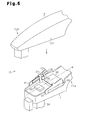
- a door handle device which is capable of operating a door opening/losing mechanism of a vehicle, has a door handle 10 including a case, which is formed by a first handle case 11 and a second handle case 12.
- the first handle case 11 includes a grip 11a, which is gripped by a vehicle user.
- a gap GP is defined between the grip 11a and an outer surface of an outer panel 20 of the vehicle door.
- the second handle case 12 is fastened to the first handle case 11 by screws or the like to cover the first handle case 11 and form an outer portion of the door handle 10.
- the case of the door handle 10 is formed by two segments (11 and 12).
- the first handle case 11 and the second handle case 12 are both formed from a highly rigid resin material.
- a support member 21 and a lever 22 of the door opening/closing mechanism are arranged in the outer panel 20.
- the second handle case 12 includes a first end 12b, which serves as a first portion, and a second end 12d, which serves as a second portion located opposite to the first end 12b with the grip 11a arranged in between.
- the support member 21 pivotally supports a pivot portion 12a, which extends from the first end 12b through the outer panel 20 and into the interior of the outer panel 20.
- An operation portion 12c which is for operating the lever 22, extends from the second end 12d through the outer panel 20 and into the interior of the outer panel 20.
- the door handle 10 pivots about the first end 12b in a direction that moves out the second end 12d. This operates the lever 22 with the operation portion 12c and opens the vehicle door as long as the vehicle door is not in a locked state.
- a circuit substrate 30, on which various types of electronic components are mounted is arranged between the grip 11a and the first end 12b.
- the interior of the handle case 11 is filled with a flexible resin (e.g., polyurethane, silicon etc.) so that the circuit substrate 30 is fixed to the case 11 and kept impervious to water due to the resin.
- a pair of lock detection electrodes 31 is mounted on the circuit substrate 30.
- the lock detection electrodes 31 are connected to a capacitance sensor 41, which detects the issuance of a door lock command of the vehicle door based on changes in the capacitance. As shown in Figs.
- each lock detection electrode 31 faces the inner surface of the second handle case 12, more specifically, the inner surfaces of the upper and lower walls 12e and 12f of the second handle case 12 and is arranged between the grip 11a and the first end 12b.
- the upward and downward directions as viewed in Fig. 4 correspond to the upward and downward directions of the vehicle.
- the lock detection electrodes 31 are located proximate to, or in contact with, the inner surfaces of the upper and lower walls 12e and 12f, respectively.
- a capacitance sensor 42 has an unlock detection electrode 32 electrically connected to a specific electrode that serves as a sensor input terminal arranged on the circuit substrate 30. The unlock detection electrode 32 detects the issuance of a door unlock command of the vehicle door based on changes in the capacitance.
- the unlock detection electrode 32 is arranged on the inner surface of the grip 11a.
- An antenna 33 is arranged on the inner surface of the grip 11a. Necessary information such as user authentication is exchanged between the antenna 33 and a portable device (not shown), which is carried by the vehicle user.
- the antenna 33 is electrically connected to a specific electrode that serves as a power supply terminal arranged on the circuit substrate 30.
- a sensor IC 40 including the capacitance sensors 41 and 42 is mounted on the circuit substrate 30. The supply of power to the sensor IC 40, the antenna 33, and the like, and the retrieval of the necessary information, such as output signals from the sensor IC 40, by a door control unit 60 (see Fig. 4 ) are performed through a connector 34, which is arranged on the rear surface of the circuit substrate 30.
- the lock detection electrodes 31 are arranged in symmetry with respect to a center line m extending in the longitudinal direction of the door handle 10 from the first end 12b towards the second end 12d along the middle of the space between the upper and lower walls 12e and 12f.
- Each lock detection electrode 31 includes a connecting portion 31c serving as a supporting portion in the longitudinally central part of the lock detection electrode 31.
- the connecting portion 31c is connected to the circuit substrate 30 so as to extend through the circuit substrate 30. This supports the lock detection electrode 31 on the circuit substrate 30 and electrically connects the lock detection electrode 31 to a circuit pattern on the circuit substrate 30.
- a plate-shaped auxiliary electrode 35 extends upright from the circuit substrate 30.
- the auxiliary electrode 35 extends from the circuit substrate 30 to a predetermined height.
- the auxiliary electrode 35 is located between the lock detection electrodes 31.
- the two ends of the auxiliary electrode 35 are respectively connected to the two lock detection electrodes 31.
- the two ends of the auxiliary electrode 35 are respectively connected to the connecting portions 31 c of the two lock detection electrodes 31.
- the auxiliary electrode 35 is fixed to the circuit substrate 30 by the lock detection electrodes 31. Further, the auxiliary electrode 35 electrically and mechanically connects the two lock detection electrodes 31. Pressing is performed to integrally form the lock detection electrodes 31 and the auxiliary electrode 35.
- the structure in which the lock detection electrodes 31 are arranged facing toward the inner surfaces of the upper and lower walls 12e and 12f of the second handle case 12 usually has shortcomings, which will now be discussed.
- Fig. 1 when the vehicle holds the grip 11 a and pulls the door handle 10, the door handle 10 is pivoted about the first end 12b the direction in which the second end 12d is moved out.
- the double-dashed line in Fig. 1 shows the door handle 10 in a state in which it is pulled out.
- the distance of the portion between the first end 12b and the grip 11a from the outer panel 20 of the vehicle door changes. Therefore, referring to Fig.
- the capacitance (first capacitance) C PANEL between the outer panel 20, which serves as ground GND1 and the lock detection electrode 31 changes between capacitance C PANEL (C) and capacitance C PANEL (O).
- the capacitance C PANEL (C) indicates the value of the capacitance C PANEL when the door handle 10 is not pulled, that is, when the vehicle door is closed.
- the capacitance C PANEL (O) indicates the value of the capacitance C PANEL when the door handle 10 is being pullsed, that is, when opening the vehicle door.
- the capacitance sensor 41 which detects the issuance of a door lock command of the vehicle door based on the capacitance C PANEL , may generate an erroneous detection.
- the door handle device of the present embodiment arranges the auxiliary electrode 35 on the circuit substrate 30 to prevent erroneous detections of the capacitance sensor 41.
- ground GNDB represents a ground electrode arranged on the circuit substrate 30. Due to the arrangement of the auxiliary electrode 35, the auxiliary electrode 35 and the circuit substrate 30 are capacitance-coupled so as have a capacitance (second capacitance) C BOARD in between. The capacitance C BOARD and the capacitance C PANEL have an electrically parallel relationship. Furthermore, the auxiliary electrode 35 is arranged so that the capacitance C BOARD and the capacitance C PANEL have a relationship of "C PANEL ⁇ C BOARD ". Fig.
- FIG. 4 is an equivalent circuit mainly showing a door lock system of the door handle device.
- the value of the synthesized capacitance "C PANEL + C BOARD " of the capacitance C PANEL and the capacitance C BOARD is retrieved by the capacitance sensor 41 in the sensor IC 40 via the lock detection electrode 31 and the auxiliary electrode 35.
- the influence of the capacitance "C BOARD " between the auxiliary electrode 35 and the circuit substrate 30 becomes large in the capacitance sensor 41.
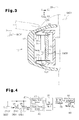
- the vehicle user may touch with his or her hand a portion of the second handle case 12 facing the lock detection electrodes 31, as shown in Fig. 3 .
- ground GND2 represents the vehicle user.
- the vehicle user and the lock detection electrode 31 are capacitance-coupled so as to form a capacitance C T in between.
- the capacitance C T and the capacitance C PANEL are in an electrically parallel relationship.
- the capacitance sensor 41 retrieves the value indicating the synthesized capacitance "C PANEL + C BOARO + C T ".
- the capacitance sensor 41 detects issuance of the door lock command when the value of the synthesized capacitance is greater than the synthesized capacitance "C PANEL + C BOARD " by an amount corresponding to the capacitance C T . In this case, even when the value of the capacitance C PANEL changes, the influence of the change on the capacitance sensor 41 is reduced by the value of the capacitance C BOARD . Thus, the lock command detection of the vehicle door with the capacitance sensor 41 is highly reliable.
- the door control unit 60 determines that a door lock command has been issued by the vehicle user based on the detection signal of the capacitance sensor 41.
- the door control unit 60 then drives a lock actuator 81 arranged in a lock mechanism 80 via a driver circuit 70 to lock the vehicle door.
- the same detection principle and operational procedures are applied to an unlock system that unlocks the vehicle door through cooperation between the unlock detection electrode 32 and the capacitance sensor 42.
- the door handle device of the present embodiment has the advantages described below.
- the auxiliary electrodes 35 described above may be used as first auxiliary electrodes 35, and a pair of second auxiliary electrodes 36 may be arranged to respectively face the inner surfaces of the lock detection electrodes 31.
- Each of the second auxiliary electrodes 36 extends parallel to the corresponding lock detection electrode 31 and is spaced by a predetermined distance from the lock detection electrode 31.
- Each second auxiliary electrode 36 includes a connecting portion 36c, which serves as a supporting portion supported by the circuit substrate 30.
- the connecting portion 36c of each second auxiliary electrode 36 is electrically connected to the ground electrode GNDB of the circuit substrate 30.
- the second auxiliary electrode 36 and the lock detection electrode 31 are thus capacitance-coupled using the ground electrode of the circuit substrate 30 as ground GNDB.
- the capacitance (third capacitance) between the second auxiliary electrode 36 and the lock detection electrode 31 is connected in parallel to the first capacitance C PANEL and the second capacitance C BOARD .
- This further increases the value of the capacitance using the ground electrode of the circuit substrate 30 as ground GNDB (second capacitance + third capacitance).
- ground GNDB second capacitance + third capacitance
- the lock detection electrodes 31 are fixed to the circuit substrate 30, and the auxiliary electrode 35 is fixed to the circuit substrate 30 by the lock detection electrodes 31.
- the auxiliary electrode 35 may be directly fixed to the circuit substrate 30, and the lock detection electrodes 31 may be fixed to the circuit substrate 30 by the auxiliary electrode 35.
- the auxiliary electrode 35 is arranged so that the relationship between the capacitance C BOARD and the capacitance C PANEL satisfies "C PANEL ⁇ C BOARD ".
- the auxiliary electrode 35 may be arranged so that the relationship between the capacitance C BOARD and the capacitance C PANEL satisfies "C PANEL > C BOARD ". That is, the auxiliary electrode capacitance-coupled to the ground electrode (GNDB) of the circuit substrate 30 only needs to connect the capacitance C BOAPD , which is formed by the auxiliary electrode, in parallel to the capacitance C PANEL , which is formed between the lock detection electrode 31 and the outer panel 20.
- GNDB ground electrode
- the lock detection electrodes 31 do not necessarily have to be arranged in vertical symmetry. If the lock detection electrode is a single electrode, the lock detection electrode may be arranged at a position facing toward the inner surface of either the upper wall or the lower wall of the door handle in a state in which the door handle is attached to the vehicle as long as it is arranged between the grip and the first end of the door handle.
- first end 12b and the second end 12d are arranged in the second handle case 12.
- just one of the first end 12b and the second end 12d may be arranged in the first handle case 11.
- the door handle 10 does not have to be formed from segments (11, 12) and may be formed integrally.
- the pair of lock detection electrodes 31 and the auxiliary electrode 35 may be formed from a single member or from a plurality of members.
Landscapes
- Engineering & Computer Science (AREA)
- Mechanical Engineering (AREA)
- Lock And Its Accessories (AREA)
Applications Claiming Priority (2)
| Application Number | Priority Date | Filing Date | Title |
|---|---|---|---|
| JP2007196121A JP4938580B2 (ja) | 2007-07-27 | 2007-07-27 | ドアハンドル装置 |
| PCT/JP2008/063389 WO2009017049A1 (fr) | 2007-07-27 | 2008-07-25 | Dispositif de poignée de portière |
Publications (3)
| Publication Number | Publication Date |
|---|---|
| EP2177695A1 true EP2177695A1 (fr) | 2010-04-21 |
| EP2177695A4 EP2177695A4 (fr) | 2013-08-28 |
| EP2177695B1 EP2177695B1 (fr) | 2014-08-20 |
Family
ID=40304279
Family Applications (1)
| Application Number | Title | Priority Date | Filing Date |
|---|---|---|---|
| EP20080791633 Not-in-force EP2177695B1 (fr) | 2007-07-27 | 2008-07-25 | Dispositif de poignée de portière |
Country Status (5)
| Country | Link |
|---|---|
| US (1) | US8403384B2 (fr) |
| EP (1) | EP2177695B1 (fr) |
| JP (1) | JP4938580B2 (fr) |
| CN (1) | CN101778983B (fr) |
| WO (1) | WO2009017049A1 (fr) |
Cited By (6)
| Publication number | Priority date | Publication date | Assignee | Title |
|---|---|---|---|---|
| US20100187838A1 (en) * | 2007-07-27 | 2010-07-29 | Aisin Seiki Kabushiki Kaisha | Door handle device |
| EP2412897A3 (fr) * | 2010-07-26 | 2012-10-31 | Aisin Seiki Kabushiki Kaisha | Dispositif de poignée de porte pour véhicule |
| JP2014156753A (ja) * | 2013-02-18 | 2014-08-28 | Yuhshin Co Ltd | ドアハンドル装置 |
| EP2592201A3 (fr) * | 2011-11-11 | 2015-03-04 | Huf Hülsbeck & Fürst GmbH & Co. KG | Poignée |
| EP2458119A3 (fr) * | 2010-11-26 | 2017-06-21 | Aisin Seiki Kabushiki Kaisha | Dispositif de poignée de porte |
| CN110499973A (zh) * | 2018-05-16 | 2019-11-26 | 爱信精机株式会社 | 车辆用人检测装置 |
Families Citing this family (22)
| Publication number | Priority date | Publication date | Assignee | Title |
|---|---|---|---|---|
| US20070162761A1 (en) | 2005-12-23 | 2007-07-12 | Davis Bruce L | Methods and Systems to Help Detect Identity Fraud |
| US8010511B2 (en) | 2006-08-29 | 2011-08-30 | Attributor Corporation | Content monitoring and compliance enforcement |
| US8707459B2 (en) | 2007-01-19 | 2014-04-22 | Digimarc Corporation | Determination of originality of content |
| US9179200B2 (en) | 2007-03-14 | 2015-11-03 | Digimarc Corporation | Method and system for determining content treatment |
| JP4751861B2 (ja) | 2007-07-27 | 2011-08-17 | アイシン精機株式会社 | ドアハンドル装置 |
| JP5131472B2 (ja) | 2008-07-24 | 2013-01-30 | アイシン精機株式会社 | ドアハンドル装置 |
| JP5382575B2 (ja) * | 2009-03-31 | 2014-01-08 | 株式会社フジクラ | ロック・アンロック制御装置 |
| IT1396932B1 (it) * | 2009-11-20 | 2012-12-20 | Valeo Spa | Dispositivo di comando di sblocco di maniglia di veicolo munita di un organo di comando esterno. |
| DE102011002105A1 (de) * | 2011-04-15 | 2012-10-18 | Huf Hülsbeck & Fürst Gmbh & Co. Kg | Kraftfahrzeugtürgriff |
| US9957737B2 (en) | 2012-06-29 | 2018-05-01 | Ford Global Technologies, Llc | Flush-mounted door handle for vehicles |
| US8701353B2 (en) | 2012-06-29 | 2014-04-22 | Ford Global Technologies, Llc | Deployable door handle for vehicles |
| FR2999833B1 (fr) * | 2012-12-19 | 2015-01-23 | Continental Automotive France | Dispositif de mesure d'une variation d'une capacite et procede de mesure associe |
| JP2016142046A (ja) * | 2015-02-02 | 2016-08-08 | アイシン精機株式会社 | 開閉体開閉装置 |
| JP6651710B2 (ja) * | 2015-05-08 | 2020-02-19 | 三井金属アクト株式会社 | 自動車用ドアロック装置 |
| US11286694B2 (en) * | 2015-07-13 | 2022-03-29 | Huf Hülsbeck & Fürst Gmbh & Co. Kg | Exterior door handle for a vehicle |
| JP2017141645A (ja) * | 2016-02-12 | 2017-08-17 | 株式会社東海理化電機製作所 | ドアハンドル装置 |
| CN107976576A (zh) * | 2016-10-24 | 2018-05-01 | 精工爱普生株式会社 | 电子元器件传送装置以及电子元器件检查装置 |
| US10385594B2 (en) | 2017-03-06 | 2019-08-20 | Trimark Corporation | Power locking door handle with capacitive sensing |
| JP6831291B2 (ja) * | 2017-04-28 | 2021-02-17 | 株式会社ユーシン | 車両用ドアハンドル装置 |
| WO2019181238A1 (fr) | 2018-03-23 | 2019-09-26 | アルプスアルパイン株式会社 | Poignée de porte |
| JP2021080626A (ja) * | 2018-03-23 | 2021-05-27 | アルプスアルパイン株式会社 | ドアハンドル |
| JP7292610B2 (ja) * | 2019-09-04 | 2023-06-19 | 株式会社アイシン | 車両用ドア制御装置 |
Citations (3)
| Publication number | Priority date | Publication date | Assignee | Title |
|---|---|---|---|---|
| US6075294A (en) * | 1996-04-27 | 2000-06-13 | Huf Hulsbeck & Furst Gmbh & Co. Kg | Locking system, particularly for motor vehicles |
| US20030122556A1 (en) * | 2001-11-20 | 2003-07-03 | Masahiko Sueyoshi | Vehicle door handle system |
| EP1394946A2 (fr) * | 2002-08-29 | 2004-03-03 | Aisin Seiki Kabushiki Kaisha | Dispositif de détection du corps humain et dispositif de verrouillage |
Family Cites Families (31)
| Publication number | Priority date | Publication date | Assignee | Title |
|---|---|---|---|---|
| JP3648396B2 (ja) * | 1998-12-02 | 2005-05-18 | トヨタ自動車株式会社 | 車両用のドアハンドル |
| DE10015887C1 (de) * | 2000-03-30 | 2002-01-17 | Huf Huelsbeck & Fuerst Gmbh | Zugangssystem für ein Fahrzeug |
| JP2002057564A (ja) | 2000-08-11 | 2002-02-22 | Aisin Seiki Co Ltd | 人体検出器 |
| FR2813630B1 (fr) * | 2000-09-05 | 2003-08-01 | Valeo Electronique | Procede pour verrouiller automatiquement un ouvrant de vehicule a l'aide d'un systeme d'acces mains libres et d'un capteur d'approche |
| JP3502848B2 (ja) | 2001-03-28 | 2004-03-02 | 株式会社ホンダロック | 車両用ドアの施・解錠意思確認装置 |
| DE10132925A1 (de) * | 2001-06-12 | 2003-01-02 | Bosch Gmbh Robert | Türaussengriffanordnung |
| FR2830110B1 (fr) | 2001-09-27 | 2004-10-08 | Valeo Electronique | Capteur de presence destine a etre integre dans une poignee d'un ouvrant de vehicule automobile |
| WO2003029049A2 (fr) | 2001-10-01 | 2003-04-10 | Donnelly Corporation | Ensemble poignee de vehicule avec antenne |
| JP4003453B2 (ja) * | 2001-12-26 | 2007-11-07 | アイシン精機株式会社 | 人体検出装置 |
| EP1476621A1 (fr) | 2002-02-22 | 2004-11-17 | Schaffner Emv Ag | Circuit de commande electronique comportant un capteur de proximite et un emetteur-recepteur pour un systeme de fermeture de portiere de vehicule |
| EP1476622A1 (fr) | 2002-02-22 | 2004-11-17 | Schaffner Emv Ag | Bobine d'inductance destinee notamment au systeme de fermeture d'une portiere de vehicule |
| DE10221511B4 (de) | 2002-05-14 | 2013-09-05 | Huf Hülsbeck & Fürst Gmbh & Co. Kg | Schlüssellose Sicherheits-/Betätigungseinrichtung für Kraftfahrzeuge |
| JP4161664B2 (ja) * | 2002-09-27 | 2008-10-08 | アイシン精機株式会社 | 車両用ドアハンドル装置 |
| JP4084640B2 (ja) | 2002-11-20 | 2008-04-30 | 株式会社ホンダロック | 車両用ドアのアウトハンドル装置 |
| DE10255439B4 (de) * | 2002-11-28 | 2008-07-17 | Daimler Ag | Griffanordnung für eine Fahrzeugtür |
| DE112004001103T5 (de) * | 2003-06-20 | 2006-05-24 | Kabushiki Kaisha Honda Lock | Fahrzeugtür-Außengriffsystem |
| KR20060069500A (ko) * | 2003-09-26 | 2006-06-21 | 마쯔시다덴기산교 가부시키가이샤 | 도어 핸들 장치 및 이것을 구비한 키리스 엔트리 장치 |
| JP4098215B2 (ja) * | 2003-10-29 | 2008-06-11 | アイシン精機株式会社 | 車両用人体検出装置 |
| DE602005021841D1 (de) * | 2004-03-30 | 2010-07-29 | Honda Lock Kk | Türgriffanordnung für eine Kraftfahrzeugtür |
| JP4240307B2 (ja) * | 2004-06-22 | 2009-03-18 | アイシン精機株式会社 | 車両用ドア開閉装置 |
| DE102004063009A1 (de) | 2004-12-22 | 2006-07-13 | Huf Hülsbeck & Fürst Gmbh & Co. Kg | Vorrichtung zum Betätigen eines elektrischen Schließsystems und/oder eines in der Tür oder Klappe oder dergleichen eingebauten Schlosses für Fahrzeuge |
| EP1738980B1 (fr) * | 2005-06-29 | 2008-06-11 | Huf Hülsbeck & Fürst GmbH & Co. KG | Système de verrouillage |
| DE102005041551A1 (de) | 2005-08-31 | 2007-03-01 | Huf Hülsbeck & Fürst Gmbh & Co. Kg | Aussengriff für eine Tür oder Klappe an einem Kraftfahrzeug |
| JP2007138565A (ja) * | 2005-11-18 | 2007-06-07 | Aisin Seiki Co Ltd | 車両用ドア開閉装置 |
| JP4639141B2 (ja) * | 2005-11-18 | 2011-02-23 | 株式会社ホンダロック | アンテナ内蔵装置 |
| JP4600323B2 (ja) * | 2006-03-15 | 2010-12-15 | アイシン精機株式会社 | 車両用のドアハンドル |
| DE602007000993D1 (de) * | 2006-03-16 | 2009-06-10 | Aisin Seiki | Türgriffvorrichtung für Fahrzeuge |
| JP4947348B2 (ja) * | 2006-09-13 | 2012-06-06 | アイシン精機株式会社 | 車両用ドアハンドル装置 |
| JP4751860B2 (ja) | 2007-07-27 | 2011-08-17 | アイシン精機株式会社 | ドアハンドル装置 |
| JP4751861B2 (ja) | 2007-07-27 | 2011-08-17 | アイシン精機株式会社 | ドアハンドル装置 |
| JP5324816B2 (ja) * | 2008-05-08 | 2013-10-23 | アイシン精機株式会社 | 車両用ドアハンドル |
-
2007
- 2007-07-27 JP JP2007196121A patent/JP4938580B2/ja not_active Expired - Fee Related
-
2008
- 2008-07-25 EP EP20080791633 patent/EP2177695B1/fr not_active Not-in-force
- 2008-07-25 US US12/670,583 patent/US8403384B2/en active Active
- 2008-07-25 CN CN200880025674XA patent/CN101778983B/zh not_active Expired - Fee Related
- 2008-07-25 WO PCT/JP2008/063389 patent/WO2009017049A1/fr active Application Filing
Patent Citations (3)
| Publication number | Priority date | Publication date | Assignee | Title |
|---|---|---|---|---|
| US6075294A (en) * | 1996-04-27 | 2000-06-13 | Huf Hulsbeck & Furst Gmbh & Co. Kg | Locking system, particularly for motor vehicles |
| US20030122556A1 (en) * | 2001-11-20 | 2003-07-03 | Masahiko Sueyoshi | Vehicle door handle system |
| EP1394946A2 (fr) * | 2002-08-29 | 2004-03-03 | Aisin Seiki Kabushiki Kaisha | Dispositif de détection du corps humain et dispositif de verrouillage |
Non-Patent Citations (1)
| Title |
|---|
| See also references of WO2009017049A1 * |
Cited By (8)
| Publication number | Priority date | Publication date | Assignee | Title |
|---|---|---|---|---|
| US20100187838A1 (en) * | 2007-07-27 | 2010-07-29 | Aisin Seiki Kabushiki Kaisha | Door handle device |
| EP2412897A3 (fr) * | 2010-07-26 | 2012-10-31 | Aisin Seiki Kabushiki Kaisha | Dispositif de poignée de porte pour véhicule |
| US9033379B2 (en) | 2010-07-26 | 2015-05-19 | Aisin Seiki Kabushiki Kaisha | Door handle device for vehicle |
| EP2458119A3 (fr) * | 2010-11-26 | 2017-06-21 | Aisin Seiki Kabushiki Kaisha | Dispositif de poignée de porte |
| EP2592201A3 (fr) * | 2011-11-11 | 2015-03-04 | Huf Hülsbeck & Fürst GmbH & Co. KG | Poignée |
| JP2014156753A (ja) * | 2013-02-18 | 2014-08-28 | Yuhshin Co Ltd | ドアハンドル装置 |
| CN110499973A (zh) * | 2018-05-16 | 2019-11-26 | 爱信精机株式会社 | 车辆用人检测装置 |
| CN110499973B (zh) * | 2018-05-16 | 2021-08-20 | 爱信精机株式会社 | 车辆用人检测装置 |
Also Published As
| Publication number | Publication date |
|---|---|
| EP2177695A4 (fr) | 2013-08-28 |
| CN101778983B (zh) | 2013-03-20 |
| US8403384B2 (en) | 2013-03-26 |
| US20100192329A1 (en) | 2010-08-05 |
| EP2177695B1 (fr) | 2014-08-20 |
| JP4938580B2 (ja) | 2012-05-23 |
| JP2009030360A (ja) | 2009-02-12 |
| CN101778983A (zh) | 2010-07-14 |
| WO2009017049A1 (fr) | 2009-02-05 |
Similar Documents
| Publication | Publication Date | Title |
|---|---|---|
| EP2177695B1 (fr) | Dispositif de poignée de portière | |
| EP2175091B1 (fr) | Dispositif de poignée de portière | |
| EP2172605B1 (fr) | Dispositif de poignée de portière | |
| EP2148025B1 (fr) | Appareil de poignée de porte | |
| JP5022483B2 (ja) | 車両用ドアハンドル装置 | |
| US11286694B2 (en) | Exterior door handle for a vehicle | |
| EP2458119A2 (fr) | Dispositif de poignée de porte | |
| JP4098215B2 (ja) | 車両用人体検出装置 | |
| EP3375960B1 (fr) | Poignée de porte à verrouillage électrique à détection capacitive | |
| CN205558558U (zh) | 开闭体开闭装置 | |
| CN109415916B (zh) | 车门构造 | |
| US20240218723A1 (en) | Control system, control apparatus, and control method | |
| JP4079646B2 (ja) | 車両用ドアアウトサイドハンドル装置 | |
| JP4970143B2 (ja) | ドア開閉装置 | |
| JP4889010B2 (ja) | キーボックス |
Legal Events
| Date | Code | Title | Description |
|---|---|---|---|
| PUAI | Public reference made under article 153(3) epc to a published international application that has entered the european phase |
Free format text: ORIGINAL CODE: 0009012 |
|
| 17P | Request for examination filed |
Effective date: 20100125 |
|
| AK | Designated contracting states |
Kind code of ref document: A1 Designated state(s): AT BE BG CH CY CZ DE DK EE ES FI FR GB GR HR HU IE IS IT LI LT LU LV MC MT NL NO PL PT RO SE SI SK TR |
|
| AX | Request for extension of the european patent |
Extension state: AL BA MK RS |
|
| DAX | Request for extension of the european patent (deleted) | ||
| RAP1 | Party data changed (applicant data changed or rights of an application transferred) |
Owner name: AISIN SEIKI KABUSHIKI KAISHA Owner name: TOYOTA JIDOSHA KABUSHIKI KAISHA |
|
| A4 | Supplementary search report drawn up and despatched |
Effective date: 20130725 |
|
| RIC1 | Information provided on ipc code assigned before grant |
Ipc: B60J 5/00 20060101ALI20130719BHEP Ipc: E05B 49/00 20060101ALI20130719BHEP Ipc: B60R 25/00 20130101ALI20130719BHEP Ipc: E05B 1/00 20060101AFI20130719BHEP |
|
| GRAJ | Information related to disapproval of communication of intention to grant by the applicant or resumption of examination proceedings by the epo deleted |
Free format text: ORIGINAL CODE: EPIDOSDIGR1 |
|
| GRAP | Despatch of communication of intention to grant a patent |
Free format text: ORIGINAL CODE: EPIDOSNIGR1 |
|
| INTG | Intention to grant announced |
Effective date: 20140410 |
|
| GRAS | Grant fee paid |
Free format text: ORIGINAL CODE: EPIDOSNIGR3 |
|
| GRAA | (expected) grant |
Free format text: ORIGINAL CODE: 0009210 |
|
| AK | Designated contracting states |
Kind code of ref document: B1 Designated state(s): AT BE BG CH CY CZ DE DK EE ES FI FR GB GR HR HU IE IS IT LI LT LU LV MC MT NL NO PL PT RO SE SI SK TR |
|
| REG | Reference to a national code |
Ref country code: GB Ref legal event code: FG4D |
|
| REG | Reference to a national code |
Ref country code: CH Ref legal event code: EP |
|
| REG | Reference to a national code |
Ref country code: AT Ref legal event code: REF Ref document number: 683576 Country of ref document: AT Kind code of ref document: T Effective date: 20140915 |
|
| REG | Reference to a national code |
Ref country code: IE Ref legal event code: FG4D |
|
| REG | Reference to a national code |
Ref country code: DE Ref legal event code: R096 Ref document number: 602008033996 Country of ref document: DE Effective date: 20141002 |
|
| REG | Reference to a national code |
Ref country code: AT Ref legal event code: MK05 Ref document number: 683576 Country of ref document: AT Kind code of ref document: T Effective date: 20140820 |
|
| REG | Reference to a national code |
Ref country code: NL Ref legal event code: VDEP Effective date: 20140820 |
|
| REG | Reference to a national code |
Ref country code: LT Ref legal event code: MG4D |
|
| PG25 | Lapsed in a contracting state [announced via postgrant information from national office to epo] |
Ref country code: ES Free format text: LAPSE BECAUSE OF FAILURE TO SUBMIT A TRANSLATION OF THE DESCRIPTION OR TO PAY THE FEE WITHIN THE PRESCRIBED TIME-LIMIT Effective date: 20140820 Ref country code: BG Free format text: LAPSE BECAUSE OF FAILURE TO SUBMIT A TRANSLATION OF THE DESCRIPTION OR TO PAY THE FEE WITHIN THE PRESCRIBED TIME-LIMIT Effective date: 20141120 Ref country code: SE Free format text: LAPSE BECAUSE OF FAILURE TO SUBMIT A TRANSLATION OF THE DESCRIPTION OR TO PAY THE FEE WITHIN THE PRESCRIBED TIME-LIMIT Effective date: 20140820 Ref country code: LT Free format text: LAPSE BECAUSE OF FAILURE TO SUBMIT A TRANSLATION OF THE DESCRIPTION OR TO PAY THE FEE WITHIN THE PRESCRIBED TIME-LIMIT Effective date: 20140820 Ref country code: NO Free format text: LAPSE BECAUSE OF FAILURE TO SUBMIT A TRANSLATION OF THE DESCRIPTION OR TO PAY THE FEE WITHIN THE PRESCRIBED TIME-LIMIT Effective date: 20141120 Ref country code: FI Free format text: LAPSE BECAUSE OF FAILURE TO SUBMIT A TRANSLATION OF THE DESCRIPTION OR TO PAY THE FEE WITHIN THE PRESCRIBED TIME-LIMIT Effective date: 20140820 Ref country code: GR Free format text: LAPSE BECAUSE OF FAILURE TO SUBMIT A TRANSLATION OF THE DESCRIPTION OR TO PAY THE FEE WITHIN THE PRESCRIBED TIME-LIMIT Effective date: 20141121 Ref country code: PT Free format text: LAPSE BECAUSE OF FAILURE TO SUBMIT A TRANSLATION OF THE DESCRIPTION OR TO PAY THE FEE WITHIN THE PRESCRIBED TIME-LIMIT Effective date: 20141222 |
|
| PG25 | Lapsed in a contracting state [announced via postgrant information from national office to epo] |
Ref country code: HR Free format text: LAPSE BECAUSE OF FAILURE TO SUBMIT A TRANSLATION OF THE DESCRIPTION OR TO PAY THE FEE WITHIN THE PRESCRIBED TIME-LIMIT Effective date: 20140820 Ref country code: IS Free format text: LAPSE BECAUSE OF FAILURE TO SUBMIT A TRANSLATION OF THE DESCRIPTION OR TO PAY THE FEE WITHIN THE PRESCRIBED TIME-LIMIT Effective date: 20141220 Ref country code: AT Free format text: LAPSE BECAUSE OF FAILURE TO SUBMIT A TRANSLATION OF THE DESCRIPTION OR TO PAY THE FEE WITHIN THE PRESCRIBED TIME-LIMIT Effective date: 20140820 Ref country code: LV Free format text: LAPSE BECAUSE OF FAILURE TO SUBMIT A TRANSLATION OF THE DESCRIPTION OR TO PAY THE FEE WITHIN THE PRESCRIBED TIME-LIMIT Effective date: 20140820 |
|
| PG25 | Lapsed in a contracting state [announced via postgrant information from national office to epo] |
Ref country code: NL Free format text: LAPSE BECAUSE OF FAILURE TO SUBMIT A TRANSLATION OF THE DESCRIPTION OR TO PAY THE FEE WITHIN THE PRESCRIBED TIME-LIMIT Effective date: 20140820 |
|
| PG25 | Lapsed in a contracting state [announced via postgrant information from national office to epo] |
Ref country code: SK Free format text: LAPSE BECAUSE OF FAILURE TO SUBMIT A TRANSLATION OF THE DESCRIPTION OR TO PAY THE FEE WITHIN THE PRESCRIBED TIME-LIMIT Effective date: 20140820 Ref country code: CZ Free format text: LAPSE BECAUSE OF FAILURE TO SUBMIT A TRANSLATION OF THE DESCRIPTION OR TO PAY THE FEE WITHIN THE PRESCRIBED TIME-LIMIT Effective date: 20140820 Ref country code: IT Free format text: LAPSE BECAUSE OF FAILURE TO SUBMIT A TRANSLATION OF THE DESCRIPTION OR TO PAY THE FEE WITHIN THE PRESCRIBED TIME-LIMIT Effective date: 20140820 Ref country code: DK Free format text: LAPSE BECAUSE OF FAILURE TO SUBMIT A TRANSLATION OF THE DESCRIPTION OR TO PAY THE FEE WITHIN THE PRESCRIBED TIME-LIMIT Effective date: 20140820 Ref country code: EE Free format text: LAPSE BECAUSE OF FAILURE TO SUBMIT A TRANSLATION OF THE DESCRIPTION OR TO PAY THE FEE WITHIN THE PRESCRIBED TIME-LIMIT Effective date: 20140820 Ref country code: RO Free format text: LAPSE BECAUSE OF FAILURE TO SUBMIT A TRANSLATION OF THE DESCRIPTION OR TO PAY THE FEE WITHIN THE PRESCRIBED TIME-LIMIT Effective date: 20140820 |
|
| REG | Reference to a national code |
Ref country code: DE Ref legal event code: R097 Ref document number: 602008033996 Country of ref document: DE |
|
| PG25 | Lapsed in a contracting state [announced via postgrant information from national office to epo] |
Ref country code: PL Free format text: LAPSE BECAUSE OF FAILURE TO SUBMIT A TRANSLATION OF THE DESCRIPTION OR TO PAY THE FEE WITHIN THE PRESCRIBED TIME-LIMIT Effective date: 20140820 |
|
| PLBE | No opposition filed within time limit |
Free format text: ORIGINAL CODE: 0009261 |
|
| STAA | Information on the status of an ep patent application or granted ep patent |
Free format text: STATUS: NO OPPOSITION FILED WITHIN TIME LIMIT |
|
| 26N | No opposition filed |
Effective date: 20150521 |
|
| PG25 | Lapsed in a contracting state [announced via postgrant information from national office to epo] |
Ref country code: SI Free format text: LAPSE BECAUSE OF FAILURE TO SUBMIT A TRANSLATION OF THE DESCRIPTION OR TO PAY THE FEE WITHIN THE PRESCRIBED TIME-LIMIT Effective date: 20140820 |
|
| PG25 | Lapsed in a contracting state [announced via postgrant information from national office to epo] |
Ref country code: MC Free format text: LAPSE BECAUSE OF FAILURE TO SUBMIT A TRANSLATION OF THE DESCRIPTION OR TO PAY THE FEE WITHIN THE PRESCRIBED TIME-LIMIT Effective date: 20140820 |
|
| REG | Reference to a national code |
Ref country code: CH Ref legal event code: PL |
|
| PG25 | Lapsed in a contracting state [announced via postgrant information from national office to epo] |
Ref country code: LU Free format text: LAPSE BECAUSE OF FAILURE TO SUBMIT A TRANSLATION OF THE DESCRIPTION OR TO PAY THE FEE WITHIN THE PRESCRIBED TIME-LIMIT Effective date: 20150725 |
|
| REG | Reference to a national code |
Ref country code: IE Ref legal event code: MM4A |
|
| PG25 | Lapsed in a contracting state [announced via postgrant information from national office to epo] |
Ref country code: LI Free format text: LAPSE BECAUSE OF NON-PAYMENT OF DUE FEES Effective date: 20150731 Ref country code: CH Free format text: LAPSE BECAUSE OF NON-PAYMENT OF DUE FEES Effective date: 20150731 |
|
| REG | Reference to a national code |
Ref country code: FR Ref legal event code: PLFP Year of fee payment: 9 |
|
| PG25 | Lapsed in a contracting state [announced via postgrant information from national office to epo] |
Ref country code: BE Free format text: LAPSE BECAUSE OF FAILURE TO SUBMIT A TRANSLATION OF THE DESCRIPTION OR TO PAY THE FEE WITHIN THE PRESCRIBED TIME-LIMIT Effective date: 20140820 Ref country code: IE Free format text: LAPSE BECAUSE OF NON-PAYMENT OF DUE FEES Effective date: 20150725 |
|
| PG25 | Lapsed in a contracting state [announced via postgrant information from national office to epo] |
Ref country code: MT Free format text: LAPSE BECAUSE OF FAILURE TO SUBMIT A TRANSLATION OF THE DESCRIPTION OR TO PAY THE FEE WITHIN THE PRESCRIBED TIME-LIMIT Effective date: 20140820 |
|
| REG | Reference to a national code |
Ref country code: DE Ref legal event code: R084 Ref document number: 602008033996 Country of ref document: DE |
|
| REG | Reference to a national code |
Ref country code: GB Ref legal event code: 746 Effective date: 20170419 |
|
| PG25 | Lapsed in a contracting state [announced via postgrant information from national office to epo] |
Ref country code: HU Free format text: LAPSE BECAUSE OF FAILURE TO SUBMIT A TRANSLATION OF THE DESCRIPTION OR TO PAY THE FEE WITHIN THE PRESCRIBED TIME-LIMIT; INVALID AB INITIO Effective date: 20080725 |
|
| REG | Reference to a national code |
Ref country code: FR Ref legal event code: PLFP Year of fee payment: 10 |
|
| PG25 | Lapsed in a contracting state [announced via postgrant information from national office to epo] |
Ref country code: CY Free format text: LAPSE BECAUSE OF FAILURE TO SUBMIT A TRANSLATION OF THE DESCRIPTION OR TO PAY THE FEE WITHIN THE PRESCRIBED TIME-LIMIT Effective date: 20140820 |
|
| PG25 | Lapsed in a contracting state [announced via postgrant information from national office to epo] |
Ref country code: TR Free format text: LAPSE BECAUSE OF FAILURE TO SUBMIT A TRANSLATION OF THE DESCRIPTION OR TO PAY THE FEE WITHIN THE PRESCRIBED TIME-LIMIT Effective date: 20140820 |
|
| REG | Reference to a national code |
Ref country code: FR Ref legal event code: PLFP Year of fee payment: 11 |
|
| PGFP | Annual fee paid to national office [announced via postgrant information from national office to epo] |
Ref country code: FR Payment date: 20200611 Year of fee payment: 13 |
|
| PGFP | Annual fee paid to national office [announced via postgrant information from national office to epo] |
Ref country code: GB Payment date: 20200716 Year of fee payment: 13 |
|
| PGFP | Annual fee paid to national office [announced via postgrant information from national office to epo] |
Ref country code: DE Payment date: 20210629 Year of fee payment: 14 |
|
| GBPC | Gb: european patent ceased through non-payment of renewal fee |
Effective date: 20210725 |
|
| PG25 | Lapsed in a contracting state [announced via postgrant information from national office to epo] |
Ref country code: GB Free format text: LAPSE BECAUSE OF NON-PAYMENT OF DUE FEES Effective date: 20210725 |
|
| PG25 | Lapsed in a contracting state [announced via postgrant information from national office to epo] |
Ref country code: FR Free format text: LAPSE BECAUSE OF NON-PAYMENT OF DUE FEES Effective date: 20210731 |
|
| REG | Reference to a national code |
Ref country code: DE Ref legal event code: R119 Ref document number: 602008033996 Country of ref document: DE |
|
| PG25 | Lapsed in a contracting state [announced via postgrant information from national office to epo] |
Ref country code: DE Free format text: LAPSE BECAUSE OF NON-PAYMENT OF DUE FEES Effective date: 20230201 |