EP2166830B1 - Saatgutsortierer - Google Patents
Saatgutsortierer Download PDFInfo
- Publication number
- EP2166830B1 EP2166830B1 EP08756459.7A EP08756459A EP2166830B1 EP 2166830 B1 EP2166830 B1 EP 2166830B1 EP 08756459 A EP08756459 A EP 08756459A EP 2166830 B1 EP2166830 B1 EP 2166830B1
- Authority
- EP
- European Patent Office
- Prior art keywords
- seed
- seeds
- image data
- imaging
- loading
- Prior art date
- Legal status (The legal status is an assumption and is not a legal conclusion. Google has not performed a legal analysis and makes no representation as to the accuracy of the status listed.)
- Active
Links
Images


Classifications
-
- G—PHYSICS
- G01—MEASURING; TESTING
- G01N—INVESTIGATING OR ANALYSING MATERIALS BY DETERMINING THEIR CHEMICAL OR PHYSICAL PROPERTIES
- G01N21/00—Investigating or analysing materials by the use of optical means, i.e. using sub-millimetre waves, infrared, visible or ultraviolet light
- G01N21/84—Systems specially adapted for particular applications
- G01N21/85—Investigating moving fluids or granular solids
-
- B—PERFORMING OPERATIONS; TRANSPORTING
- B07—SEPARATING SOLIDS FROM SOLIDS; SORTING
- B07C—POSTAL SORTING; SORTING INDIVIDUAL ARTICLES, OR BULK MATERIAL FIT TO BE SORTED PIECE-MEAL, e.g. BY PICKING
- B07C5/00—Sorting according to a characteristic or feature of the articles or material being sorted, e.g. by control effected by devices which detect or measure such characteristic or feature; Sorting by manually actuated devices, e.g. switches
- B07C5/04—Sorting according to size
- B07C5/10—Sorting according to size measured by light-responsive means
-
- B—PERFORMING OPERATIONS; TRANSPORTING
- B07—SEPARATING SOLIDS FROM SOLIDS; SORTING
- B07C—POSTAL SORTING; SORTING INDIVIDUAL ARTICLES, OR BULK MATERIAL FIT TO BE SORTED PIECE-MEAL, e.g. BY PICKING
- B07C5/00—Sorting according to a characteristic or feature of the articles or material being sorted, e.g. by control effected by devices which detect or measure such characteristic or feature; Sorting by manually actuated devices, e.g. switches
- B07C5/34—Sorting according to other particular properties
- B07C5/342—Sorting according to other particular properties according to optical properties, e.g. colour
- B07C5/3422—Sorting according to other particular properties according to optical properties, e.g. colour using video scanning devices, e.g. TV-cameras
-
- B—PERFORMING OPERATIONS; TRANSPORTING
- B07—SEPARATING SOLIDS FROM SOLIDS; SORTING
- B07C—POSTAL SORTING; SORTING INDIVIDUAL ARTICLES, OR BULK MATERIAL FIT TO BE SORTED PIECE-MEAL, e.g. BY PICKING
- B07C5/00—Sorting according to a characteristic or feature of the articles or material being sorted, e.g. by control effected by devices which detect or measure such characteristic or feature; Sorting by manually actuated devices, e.g. switches
- B07C5/34—Sorting according to other particular properties
- B07C5/342—Sorting according to other particular properties according to optical properties, e.g. colour
- B07C5/3425—Sorting according to other particular properties according to optical properties, e.g. colour of granular material, e.g. ore particles, grain
-
- G—PHYSICS
- G01—MEASURING; TESTING
- G01J—MEASUREMENT OF INTENSITY, VELOCITY, SPECTRAL CONTENT, POLARISATION, PHASE OR PULSE CHARACTERISTICS OF INFRARED, VISIBLE OR ULTRAVIOLET LIGHT; COLORIMETRY; RADIATION PYROMETRY
- G01J3/00—Spectrometry; Spectrophotometry; Monochromators; Measuring colours
- G01J3/02—Details
- G01J3/10—Arrangements of light sources specially adapted for spectrometry or colorimetry
-
- G—PHYSICS
- G01—MEASURING; TESTING
- G01N—INVESTIGATING OR ANALYSING MATERIALS BY DETERMINING THEIR CHEMICAL OR PHYSICAL PROPERTIES
- G01N21/00—Investigating or analysing materials by the use of optical means, i.e. using sub-millimetre waves, infrared, visible or ultraviolet light
- G01N21/17—Systems in which incident light is modified in accordance with the properties of the material investigated
- G01N21/25—Colour; Spectral properties, i.e. comparison of effect of material on the light at two or more different wavelengths or wavelength bands
- G01N21/251—Colorimeters; Construction thereof
- G01N21/253—Colorimeters; Construction thereof for batch operation, i.e. multisample apparatus
-
- G—PHYSICS
- G01—MEASURING; TESTING
- G01N—INVESTIGATING OR ANALYSING MATERIALS BY DETERMINING THEIR CHEMICAL OR PHYSICAL PROPERTIES
- G01N21/00—Investigating or analysing materials by the use of optical means, i.e. using sub-millimetre waves, infrared, visible or ultraviolet light
- G01N21/62—Systems in which the material investigated is excited whereby it emits light or causes a change in wavelength of the incident light
- G01N21/63—Systems in which the material investigated is excited whereby it emits light or causes a change in wavelength of the incident light optically excited
- G01N21/64—Fluorescence; Phosphorescence
- G01N21/6428—Measuring fluorescence of fluorescent products of reactions or of fluorochrome labelled reactive substances, e.g. measuring quenching effects, using measuring "optrodes"
-
- G—PHYSICS
- G01—MEASURING; TESTING
- G01N—INVESTIGATING OR ANALYSING MATERIALS BY DETERMINING THEIR CHEMICAL OR PHYSICAL PROPERTIES
- G01N21/00—Investigating or analysing materials by the use of optical means, i.e. using sub-millimetre waves, infrared, visible or ultraviolet light
- G01N21/62—Systems in which the material investigated is excited whereby it emits light or causes a change in wavelength of the incident light
- G01N21/63—Systems in which the material investigated is excited whereby it emits light or causes a change in wavelength of the incident light optically excited
- G01N21/64—Fluorescence; Phosphorescence
- G01N21/645—Specially adapted constructive features of fluorimeters
- G01N21/6452—Individual samples arranged in a regular 2D-array, e.g. multiwell plates
-
- G—PHYSICS
- G01—MEASURING; TESTING
- G01N—INVESTIGATING OR ANALYSING MATERIALS BY DETERMINING THEIR CHEMICAL OR PHYSICAL PROPERTIES
- G01N21/00—Investigating or analysing materials by the use of optical means, i.e. using sub-millimetre waves, infrared, visible or ultraviolet light
- G01N21/62—Systems in which the material investigated is excited whereby it emits light or causes a change in wavelength of the incident light
- G01N21/63—Systems in which the material investigated is excited whereby it emits light or causes a change in wavelength of the incident light optically excited
- G01N21/64—Fluorescence; Phosphorescence
- G01N21/645—Specially adapted constructive features of fluorimeters
- G01N21/6456—Spatial resolved fluorescence measurements; Imaging
-
- G—PHYSICS
- G01—MEASURING; TESTING
- G01J—MEASUREMENT OF INTENSITY, VELOCITY, SPECTRAL CONTENT, POLARISATION, PHASE OR PULSE CHARACTERISTICS OF INFRARED, VISIBLE OR ULTRAVIOLET LIGHT; COLORIMETRY; RADIATION PYROMETRY
- G01J3/00—Spectrometry; Spectrophotometry; Monochromators; Measuring colours
- G01J3/02—Details
- G01J3/0205—Optical elements not provided otherwise, e.g. optical manifolds, diffusers, windows
- G01J3/0218—Optical elements not provided otherwise, e.g. optical manifolds, diffusers, windows using optical fibers
-
- G—PHYSICS
- G01—MEASURING; TESTING
- G01N—INVESTIGATING OR ANALYSING MATERIALS BY DETERMINING THEIR CHEMICAL OR PHYSICAL PROPERTIES
- G01N21/00—Investigating or analysing materials by the use of optical means, i.e. using sub-millimetre waves, infrared, visible or ultraviolet light
- G01N21/01—Arrangements or apparatus for facilitating the optical investigation
- G01N21/03—Cuvette constructions
- G01N2021/0339—Holders for solids, powders
-
- G—PHYSICS
- G01—MEASURING; TESTING
- G01N—INVESTIGATING OR ANALYSING MATERIALS BY DETERMINING THEIR CHEMICAL OR PHYSICAL PROPERTIES
- G01N21/00—Investigating or analysing materials by the use of optical means, i.e. using sub-millimetre waves, infrared, visible or ultraviolet light
- G01N21/84—Systems specially adapted for particular applications
- G01N21/85—Investigating moving fluids or granular solids
- G01N2021/8592—Grain or other flowing solid samples
-
- G—PHYSICS
- G01—MEASURING; TESTING
- G01N—INVESTIGATING OR ANALYSING MATERIALS BY DETERMINING THEIR CHEMICAL OR PHYSICAL PROPERTIES
- G01N2201/00—Features of devices classified in G01N21/00
- G01N2201/06—Illumination; Optics
- G01N2201/062—LED's
- G01N2201/0627—Use of several LED's for spectral resolution
-
- G—PHYSICS
- G01—MEASURING; TESTING
- G01N—INVESTIGATING OR ANALYSING MATERIALS BY DETERMINING THEIR CHEMICAL OR PHYSICAL PROPERTIES
- G01N2201/00—Features of devices classified in G01N21/00
- G01N2201/12—Circuits of general importance; Signal processing
- G01N2201/129—Using chemometrical methods
Definitions
- the present disclosure generally relates to automated systems and methods for sorting small agricultural objects, such as seeds, based on image analysis.
- the analysis of the seeds preferably occurs not only quickly, but also reliably and with high total volume.
- arge numbers of seeds are analyzed to determine whether the seeds posses particular phenotypic traits or markers of interest.
- seeds are manually examined, weighed, identified for the presence or absence of the desired trait or marker, and then sorted.
- Such manual seed analysis is a tedious, cumbersome task subject to human error.
- US-A1-2005/082207 discloses a method for determining whether individual ones of a plurality of seeds exhibit a desired phenotype comprising: loading Individual seeds onto an imaging stage, directing light onto the seeds from a directional angle, collecting image data from two portions of each seed selected from a top portion, bottom portion, and analyzing the collected image data to determine whether each seed exhibits desired phenotype.
- US-A1-2004/072143 discloses that by directing light onto biological material at a plurality of sequentially changing spectral wavelength, particular chemical features within the material can be identified.
- US-A1-2005/082207 discloses also a system for sorting a plurality of seeds based on identifled phenotypes of the seeds, the system comprising an optics and controller station 30,42 structured and operable to collect image data of a top portion of each respective seed in a set of seeds and a bottom portion of each respective seed in the set of seeds, and analyze the collected image data to determine whether each seed exhibits a desired phenotype, and a seed loading transporting and sorting station 18,28,34 structured and operable to singulate each seed of the set of seeds from a plurality of seeds in a bulk seed hopper 12, transport the set of seeds to the optics and controller station 30 and selectively sort each seed to a respective one of a plurality of seed repositories 40 based on whether each respective seed exhibits the desired phenotype, image data of a top portion and a bottom portion of each seed has to be carried out sequentially, in view of the need to turn the tray of seeds 180° by means of the flip system.
- DE-102004063769 discloses the collection of image data simultaneously from the top and bottom portions of each seed in a plurality of seeds, by means of cameras 3a,3b arranged above and below a moving transparent belt 5; an arrangement different from the one used in US-A1-2005/082207 .
- US-A1-2004/072143 discloses the collection of image data using three different cameras, two of which are arranged at 90° to take longitudinal views, and the third to take an apical end-on view.
- the present disclosure generally relates to systems and methods of sorting individual seed from a plurality of seeds based on one or more identified phenotypes of each respective seed.
- the methods are particularly adapted for automation, which permits a greater sorting efficiency and throughput rate than was previously practical.
- With the automated seed sorting permitted by the various embodiments of the present disclosure it is possible to analyze every seed in the population, and separate those identified as having a desired characteristic or trait, e.g. haploid seeds, from the other seeds at a high throughput rate.
- the present disclosure provides a method for determining whether individual ones of a plurality of seeds exhibit a desired phenotype.
- the method includes loading individual seeds onto an imaging stage, directing light onto the seeds from at least two directional angles and at a plurality sequentially changing spectral wavelengths, collecting image data from at least three portions of each seed selected from a top-portion, a bottom portion and a plurality of side portions of each seed, at each of the spectral wavelengths, and analyzing the collected image data to determine whether each seed exhibits a desired phenotype.
- the present disclosure provides a system for sorting a plurality of seeds based on identified phenotypes of the seeds.
- the system includes an optics and controller station structured and operable to substantially simultaneously collect image data of a top portion of each respective seed in a set of seeds, a bottom portion of each respective seed in the set of seeds and a plurality of side portions of each respective seed in the set of seeds.
- the optics and controller station is additionally structured and operable to analyze the collected image data to determine whether each seed exhibits desired phenotype.
- the system further includes a seed loading, transporting and sorting station structured and operable to singulate each seed of the set of seeds from a plurality of seeds in a bulk seed hopper, transport the set of seeds to the optics and controller station, and selectively sort each seed to a respective one of a plurality of seed repositories based on whether each respective seed exhibits the desired phenotype.
- a seed loading, transporting and sorting station structured and operable to singulate each seed of the set of seeds from a plurality of seeds in a bulk seed hopper, transport the set of seeds to the optics and controller station, and selectively sort each seed to a respective one of a plurality of seed repositories based on whether each respective seed exhibits the desired phenotype.
- Figure 1 is a block diagram of an automated seed sorter system structured and operable to singulate a plurality of seeds, image, analyze and categorize each seed, and sort each seeds based on the categorization, in accordance with various embodiments of the present disclosure.
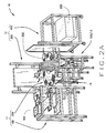
- Figure 2A is an isometric view of the seed sorter system shown in Figure 1 , in accordance with various embodiments of the present disclosure.
- FIG. 2B is a functional block diagram of the seed sorting system shown in Figure 2A , in accordance with various embodiments of the present disclosure.
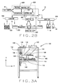
- Figure 3A is an isometric view of a seed loading station of the seed sorter system shown in Figure 2A , in accordance with various embodiments of the present disclosure.
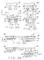
- Figures 3B and 3C are schematic side views of a picking portion of the loading station shown in Figure 3A .
- Figures 3D and 3E are schematic side views of a translation portion of the seed loading station shown in Figure 3A .
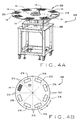
- Figure 4A is an isometric view of a seed transport subsystem of the seed sorter system shown in Figure 2A , in accordance with various embodiments of the present disclosure.
- Figure 4B is a top view of the transport subsystem shown in Figure 4A .
- Figure 5A is a front view of a first imaging station of the seed sorter system shown in Figure 2A , in accordance with various embodiments of the present disclosure.
- Figure 5B is a side view of the first imaging subsystem shown in Figure 5A .
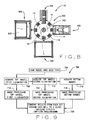
- Figure 6A is a front view of a second imaging station of the seed sorter system shown in Figure 2A , in accordance with various embodiments of the present disclosure.
- Figure 6B is a side view of the second imaging subsystem shown in Figure 6A .
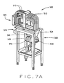
- Figure 7A is an isometric view of an off-loading station of the seed sorter system shown in Figure 2A , in accordance with various embodiments of the present disclosure.
- Figure 7B is a schematic side view of the off-loading station shown in Figure 7A .
- Figure 8 is a top view of the seed sorter system shown in Figure 2A .
- Figure 9 is a flow chart illustrating an exemplary overview of the operation of the seed sorter system shown in Figure 2A , in accordance with various embodiments of the present disclosure.
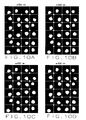
- Figures 10A - 10F are exemplary illustrations of images collected of a single tray of seeds, at various spectral bandwidths, using the seed sorter system shown in Figures 1 .
- FIG 11 is flow chart illustrating an overview of an exemplary image analysis process executed by a central controller system of the seed sorter system, shown in Figure 2A , to classify and sort the seeds imaged by the seed sorter system, in accordance with various embodiments of the present disclosure.
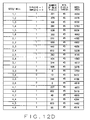
- Figures 12A-12D are exemplary pictorial and tabular illustrations showing the results of various steps of image analysis process shown in Figure 11 .
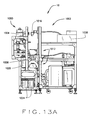
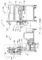
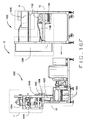
- Figure 13A is a side view of the seed sorter system shown in Figure 1 , in accordance with other various embodiments of the present disclosure.
- Figure 13B is a side view of the seed sorter system shown in Figure 13A separated into a first module and a second module, in accordance with various embodiments of the present disclosure.
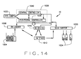
- Figure 14 is a functional block diagram of the seed sorting system shown in Figures 13A and 13B , in accordance with various embodiments of the present disclosure.
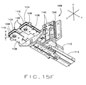
- Figure 15A is an isometric view of a load and transport subsystem of the seed sorter system shown in Figure 13A , in accordance with various embodiments of the present disclosure.
- Figure 15B is a side view of an escapement assembly of the load and transport subsystem shown in Figure 15A , in accordance with various embodiments of the present disclosure.
- Figure 15C is a top view of a retention slide of the escapement assembly shown in Figure 15B , in accordance with various embodiments of the present disclosure.
- Figure 15D is an isometric view an on-loader of the load and transport subsystem shown in Figure 15A , in accordance with various embodiments of the present disclosure.
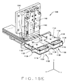
- Figure 15E is an isometric view of a pair of loading shoes of the on-loader shown in Figure 15D , in accordance with various embodiments of the present disclosure.
- Figure 15F is an isometric view of a bottom side of pair of loading shoes shown in Figure 15E , in accordance with various embodiments of the present disclosure.
- Figure 16 is an isometric view of an imaging and analysis subsystem of the seed sorter system shown in Figure 13A , in accordance with various embodiments of the present disclosure.
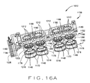
- Figure 16A is an isometric view of a portion of an imaging theater included in the imaging and analysis subsystem shown in Figure 16 , in accordance with various embodiments of the present disclosure.
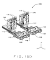
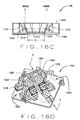
- Figure 16B is an isometric view of an imaging stage assembly included in the portion of the imaging theater shown in Figure 16A , illustrating trap-door bottoms of a plurality of imaging stages in a seed dump position, in accordance with various embodiments of the present disclosure.
- Figure 16C is a cross-sectional view along line C-C of a mirror fixture of the imaging stages 16B, in accordance with various embodiments of the present disclosure.
- Figure 16D is an isometric view of a bottom mirror assembly of the imaging theater shown in Figure 16 , in accordance with various embodiments of the present disclosure.
- Figure 16E is a cross-sectional view along line E-E of the mirror assembly shown in Figure 16D , in accordance with various embodiments of the present disclosure.
- Figure 16F is a side view of the seed sorter system shown in Figure 13A , including a dark room enclosure, in accordance with other various embodiments of the present disclosure.
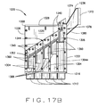
- Figure 17A is an isometric view of an off-loading and sorting subsystem of the seed sorter system shown in Figure 13A , in accordance with various embodiments of the present disclosure.
- Figure 17B is side view of an imaged seed sorter of the off-loading and sorting subsystem shown in Figure 17A , in accordance with various embodiments of the present disclosure.
- Figure 17C is a side view of a pair of sorting channels and seed diverter plugs included in the imaged seed sorter shown in Figure 17B , in accordance with various embodiments of the present disclosure.
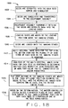
- Figure 18 is an exemplary flow chart illustrating the general operation of the seed sorter system shown in Figure 13A , in accordance with the various embodiments of the present disclosure.
- FIG 19 is flow chart illustrating an overview of an exemplary image analysis process executed by a master controller system of the seed sorter system, shown in Figure 13A , in accordance with various embodiments of the present disclosure.
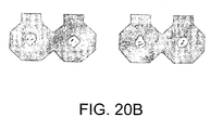
- Figures 20A , 20B and 20C are exemplary pictorial illustrations showing the results of various steps of image analysis process shown in Figure 19 :
- Figure 20A illustrates an exemplary pictorial illustration of a 'top view' image after a background mask has been applied;
- Figure 20B illustrates an exemplary pictorial illustration of a 'top view' image after background and first size threshold masks have been applied;
- Figure 20C illustrates an exemplary pictorial illustration of a 'top view' image after the background mask, the first size threshold mask and the fill and erosion mask have been applied.
- FIG. 1 is a block diagram of an automated seed sorter system 10 that is structured and operable to receive a plurality of any desired type of seed, singulate the seeds, image and analyze each singulated seed to identify desired characteristics or phenotypes, and sort the seeds based on the identified desired characteristics or phenotypes.
- the automated seed sorter system 10 includes a load and transport (L&T) subsystem 11 that is structured and operable to receive the plurality of desired type of seeds, singulate the seeds and transport the seeds to an imaging and analysis (I&A) subsystem 12.
- the I&A subsystem 12 is structured and operable to collect image data of each singulated seed and analyze the collected image data to categorize each respective seed. For example, each seed can be categorized based on whether each respective seed possesses one or more desired characteristics or phenotypes.
- An off-loading and sorting (OL&S) subsystem 13 sorts each respective seed to a particular one or more of a plurality of seed repositories based on categorization of each respective seed. For example, all seeds possessing one or more desired characteristics or phenotypes, as identified by the I&A subsystem 12, can be sorted to one or more corresponding seed repositories, while all seeds not possessing the one or more desired characteristics or phenotypes can be sorted to one or more corresponding other seed repositories. Similarly, all seeds for which it is uncertain whether the seeds possess the one or more desired characteristics or phenotypes can be sorted to one or more corresponding other seed repositories.
- the automated seed sorter system 10 additionally includes a central controller system 16 that is structured and operable to control all the operations of the seed sorter system 10. That is, the central controller system 16 simultaneously controls and coordinates the operations of each of the L&T subsystem 11, the I&A subsystem 12 and the OL&S subsystem 13 to carry out the singulation, imaging, analysis and sorting of each of the plurality of seeds loaded into the L&T subsystem 11, as described below.
- the various embodiments of the seed sorter system 10 include various stationary braces, beams, platforms, pedestals, stands, etc., to which various components, devices, mechanisms, systems, subsystems, assemblies and sub-assemblies described herein are coupled, connected and/or mounted.
- braces, beams, platforms, pedestals, stands, etc. are necessary to the construction of various embodiments of the seed sorter system 10, description of their placement, orientation and interconnections are not necessary for one skilled in the art to easily and fully comprehend the structure, function and operation of the various embodiments of the seed sorter system 10.
- braces, beams, platforms, pedestals, stands, etc. are clearly illustrated throughout the figures and, as such, their placement, orientation and interconnections are easily understood by one skilled in the art. Therefore, for simplicity, such braces, beams, platforms, pedestals, stands, etc., will be referred to herein merely as system support structures, absent further description of their placement, orientation and interconnections.
- seed sorter system 10 can be a four station rotary transport seed sorter system, wherein the L&T subsystem 11 can comprise a seed loading station 100 and a rotary seed transport subsystem 200, the I&A subsystem 12 can comprise a first seed imaging station 300 and a second imaging station 400, and the OL&S subsystem 13 can comprise a seed off-load and sort station 500. Additionally, the central controller system 16 of the seed sorter system 10 can comprise a main controller system 600.
- Figure 2B illustrates a functional block diagram of the seed sorting system shown in Figure 2A , in accordance with various embodiments.
- the seed sorter system 10 is structured and operable to isolate a plurality of seeds from a bulk seed hopper 104 and place the isolated seeds in one of a plurality of transparent multi-well seed trays 14 at the seed loading station 100.
- the seed trays 14 include a transparent bottom, for example a quartz bottom, as described below.
- the seed trays 14 are retained within an indexing transport table 202 of the transport subsystem 200 that is structured and operable to incrementally position each seed tray 14 at, i.e., adjacent to, each of the loading station 100, the first imaging station 300, the second imaging station 400 and the off-loading station 500.
- the seed sorter system 10 is additionally structured and operable to collect multiple images of at least one side of the seeds within the seed tray 14, via the first imaging station 300.
- the seed sorter system 10 is further structured and operable to collect multiple images of at least one other side of the seeds within the seed tray 14, via the second imaging station 400.
- the images collected at the first and second imaging stations 300 and 400 can be any desirable type of images.
- the images can be visual images, near infra-red (NIR) images or NMR/MRI images, or any other type images.
- NMR near infra-red
- the first and second imaging stations 300 and 400 collect a plurality of digital images at various spectral wavelengths.
- this invention contemplates the automated sorting of haploid seed on the basis of characteristics detectable with analytical instruments other than optical detection. For example, seed may be sorted based on a characteristic other than color or fluorescent markers, such as oil content.
- the invention further contemplates an apparatus and method for the automated screening and sorting of haploid seeds that is based on a variety of analytical techniques that when used in tandem can facilitate the sorting of haploid and diploid seeds in a highly automated manner, wherein MRI or NMR technology is employed either in parallel or in substitution of the optical technology of the present invention.
- seed would be sorted based on oil content, taking advantage of phenotypic differences between haploid and diploid seed in oil content, which is generally lower in haploid seed than diploid seed. It is possible to increase the difference in oil content between haploid and diploid seed by using a haploid inducer line that has been bred for increased oil, thus enabling automated phenotypic screening of a population of seeds on the basis of oil content.
- Methods for detecting oil content in seed using magnetic resonance imaging (MRI) have been disclosed in U.S. Patent No. 7,367,155 , which is incorporated herein by reference in its entirety. Oil content screening can greatly reduce the time to select haploid seed for use in germplasm improvement activities, as well as facilitate screening a much larger volume of seed.
- MRI magnetic resonance imaging
- the seed sorter system 10 illustrated and described with reference to Figures 1 through 12D can be structured and operable to implement multivariate analysis to analyze the image data of the multiple images collected at the first and second imaging stations 300 and 400. More particularly, in such embodiments, the image data can be communicated to the main controller system 600 where multivariate analysis is performed on the collected image data to identify whether individual seeds in the seed tray 14 possess one or more desired phenotypes, i.e., observable traits and/or characteristics.
- the seed sorter system 10 is structured and operable to individually off-load each seed from each seed tray 14 and sort each seed to a particular one of a plurality of seed repositories 18 based on the identified phenotype of the respective seed as determined via the multivariate analysis.
- the operation of the seed sorter system 10, as illustrated and described with reference to Figures 1 through 12D is controlled and automated by the main controller system 600 such that the operations performed by the loading station 100, the first and second imaging stations 300 and 400, and the off-loading station 500 occur substantially without need for human interaction, intervention or control.
- the operations performed by the loading station 100, the first and second imaging stations 300 and 400, and the off-loading station 500 occur substantially without need for human interaction, intervention or control.
- such actions as loading the seeds into the bulk seed hopper 104 and/or physically manipulating and/or changing the seed repositories 18 (either individually or collectively), and various other necessary hand setup and/or calibration can be performed manually with human participation.
- the main controller system 600 can include one or more processors and/or microprocessors, and one or more electronic data storage devices utilized to store and execute various custom programs, applications and/or algorithms to effectuate the operation of the seed sorter system 10.
- the main controller system 600 can comprise a specially programmed computer, or computer system, in communication with associated system devices that enable communication with and control the operations of the various stations and corresponding components 22 of the seed sorter system 10.
- the main controller system 600 is exemplarily illustrated in Figure 2A as a single unit, the main controller system 600 can be a single computer based system or a plurality of computer based subsystems networked together to coordinate the simultaneous operations of the seed sorter system 10, as described herein.
- the main controller system 600 can include a plurality of peripheral controller subsystems 604, e.g., a peripheral controller subsystem 604 for each station described herein.
- Each peripheral controller subsystem 604 can include one or more processors, microprocessors and electronic data storage devices that effectuate communication with various seed sorter system components 22, e.g., sensors, devices, mechanisms, motors, tools, etc., and are networked together with a main controller subsystem 608 to cooperatively operate all the stations, systems and subsystems of the seed sampler system 10, as illustrated and described with reference to Figures 1 through 12D .
- the main controller system 600 can comprise a single computer communicatively connected to all the various system components 22 to cooperatively operate all the stations, systems and subsystems of the seed sampler system 10, as illustrated and described with reference to Figures 1 through 12D .
- the electronic data storage device(s) (or other data storage functionality, not explicitly shown but inherently present) provided within the main controller system 600 is used to store the collected images and related image data relating to each individual seed within the seed tray 14 in a database or other suitable format. Additionally, the data storage device(s) of the main controller system 600 can also store location data received from, or derived in connection with controlling the operation of the off-loading station 500 concerning the repositories 18 where the seeds have been deposited. This location data is correlated in the database or other format with the image data on an individual seed-by-seed basis.
- the main controller system 600 communicates with various seed sorter system components 22 that include various system sensors.
- the system sensors operate to detect conditions of interest during operation of the seed sorter system 10 and communicate that information to the main controller system 600. With this information, the main controller system 600 generates control commands that effectuate the operations and actions taken by the various stations and components of the seed sorter system 10.
- the sensed condition information may concern: the successful loading of the seeds from the seed hopper 104; the positioning of the tray(s) 14 along the transport path during operation of the transport subsystem 200; the deposition of each seed into the proper seed repository 18; the status (for example, position, location, vacuum, pressure, and the like) of various component parts of the various stations 100, 300, 400 and 500; operation, maintenance, performance, and error feedback from the various components of each station 100, 300, 400 and 500 (separate from, or perhaps comprising or in conjunction with, collected data); and the like.
- sensor information that is collected and processed for use in controlling the operation of the seed sorter system 10 can include information like: device or component status; error signals; movement; stall; position; location; temperature; voltage; current; pressure; and the like, which can be monitored with respect to the operation of each of the stations, subsystems and associated components of the seed sorter system 10.
- the seed loading station 100 includes a seed feeder mechanism 106 positioned beneath an outlet 108 of the bulk seed hopper 104.
- the seed feeder mechanism generally includes a feed platform 110 operably connected to an X-axis linear actuator 114 via a translation stage 118. in operation, a large quantity of seeds is placed, either manually or via an automated means, in the bulk seed hopper 104, via a bulk seed hopper inlet 122. The seeds are then dispersed at a desired rate onto the feed platform 110 that is being linearly reciprocated along the X axis such that a leading edge 126 of the feed platform 110 linearly moves back and forth across a portion of an open top of a seed picking reservoir 130.
- the bulk seed hopper outlet 108 is structured such that as the feed platform 110 moves in a first direction toward the seed picking reservoir 130, a desired amount of seeds are dispensed onto the feed platform 110. Then, as the feed platform reciprocates in a second direction away from the seed picking reservoir 130, a leading lip 134 of the hopper outlet 108 pushes the newly dispensed seeds toward the leading edge 126 of the feed platform 110. This causes a certain amount of the seeds near the feed platform leading edge 126 to fall into the seed picking reservoir 130.
- the seed picking reservoir 130 includes a plurality of concave-shaped (inwardly sloped) bottom portions 136.
- the sloped portions 136 serve to direct the seeds, through the force of gravity, toward a bottom 138 of the seed picking reservoir 130, thereby enabling the seed loading station 100 to isolate and load individual seeds within the seed picking reservoir 130 into a corresponding seed tray 14, as described below.
- an opening 140 At the bottom 138 of each concave-shaped portion 136 is an opening 140.
- a linear air piston 142 Positioned within each opening 140 is a linear air piston 142.
- each piston 142 When positioned in a retracted, or un-actuated, position, as shown in Figure 3B , an end 144 of each piston 142 is located such that it is substantially flush with the bottom 138 of each respective opening 140. It will be recognized that "substantially flush" in this context includes a position slightly below the bottom 138 where the opening 140 may act to hold or funnel an individual seed for subsequent capture by the respective piston 142, as described below.
- each piston 142 is provided with a concave depression 146 (illustrated in dotted lines) having a perimeter that is slightly smaller than the outer diameter of the piston 142.
- the perimeter of the depression 146 is generally sized to be commensurate with, or slightly larger than, the expected average size of the seeds deposited into the seed picking reservoir 130. This allows for the handling of individual seeds of non-uniform size and/or shape.
- An air drive 148 operates under the control of the main controller system 600 to linearly move the pistons 142 between the retracted position, shown in Figure 3B , and an extended, or actuated, position, shown in Figure 3C . Although the air drive 148 is shown as a single air drive configured to simultaneously manipulate the position of each of the pistons 142, it will be understood that the seed loading station 100 could include a separate, independent air drive 148 for each piston 142.
- the concave depression 146 at each piston end 144 captures an individual one of the seeds from the collected mass of seeds (generally indicated at 150) in the seed picking reservoir 130.
- the captured seeds are raised above the collected mass of seeds 150 to a location approximately at a top edge 152 of the seed picking reservoir 130.
- the seed loading station 100 further includes a pick and place device 154.
- the pick and place device 154 generally includes a head unit 156 operably coupled to an X-Y translation stage operable to bi-directionally move the head unit along the X and Y axes.
- the head unit 156 includes a plurality of vacuum cups 160 arranged and oriented to longitudinally, collinearly correspond with the pistons 142. Accordingly, when the pistons 142 are in the extended position, the captured seeds on each piston are positioned adjacent a corresponding one of the vacuum cups 160.
- each vacuum cup 160 can be spring loaded such that each vacuum cup 160 contacts the respective seeds with desired, non-damaging pressure.
- a slight vacuum is drawn (illustrated by dotted arrows 162) to remove the seeds from the pistons and hold the seeds within the vacuum cups 160.
- the vacuum pressure used to remove and retain the seeds is controlled by the main controller system 600. This vacuum can be drawn using Venturi forces in a manner well known in the art.
- the pistons 142 are then withdrawn to the retracted position, leaving the head unit 156 'loaded', i.e., having the seeds retained within the vacuum cups 160, and the process for capturing a subsequent set of seeds is begun.
- each seed tray includes a plurality of wells 30 and each individual seed is placed in a corresponding one of the seed tray wells 30.
- the X-Y translation stage 158 moves the head unit 156, including the vacuum cups 160 and the seeds held therein, along the X-axis to a position above a seed tray 14 positioned adjacent the seed loading station 100.
- the X-Y translation stage 158 positions the 'loaded' head unit 156 over the respective seed tray 14 such that each vacuum cup 160 and respective seed held therein is aligned above a respective seed tray well 30.
- the indexing transport table 202 is controlled by the main controller system 600 to incrementally advance one or more seed trays 14 to sequentially position each seed tray 14 adjacent each of the loading station 100, the first imaging station 300, the second imaging station 400 and the off-loading station 500.
- Each vacuum cup 160 under the control of the main controller system 600, then releases the respective seeds, thereby depositing each seed in the corresponding seed tray well 30.
- the vacuum cups 160 can emit a positive pressure to aid gravitational forces in releasing the seeds from the vacuum cups 160 and depositing the seeds in the respective seed tray wells 30.
- the indexing transport table 202 and the seed trays 14 can be a distance below the head unit 156 such that movement of the head unit 156 along the Y axis is required to accurately and consistently deposit the seeds in the seed tray wells 30.
- the X-Y translation stage 158 under the control of the main controller system 600, operates to move the head unit 156 along the Y axis to position the seeds retained within the vacuum cups 160 in close proximity of the seed tray wells 30. The seeds can then be released, or ejected, from the vacuum cups 160 such that each seed is deposited into a respective one of the seed tray wells 30.
- the head unit 156 includes the same number and arrangement of vacuum cups 160 as the wells 30 in the seed trays 14. For example, if the seed trays 14 have twenty-four wells 30 arranged in a 4x6 array format, the head unit 156 will also include twenty-four vacuum cups 160 arranged in a 4x6 array format that corresponds with the 4x6 array format of the seed tray wells 30. In this way, one seed tray 14 can be fully loaded with seeds using a single 'pick-and-place' operation of the pick and place device 154, as described above.
- the head unit 156 can include an even submultiple number and arrangement of vacuum cups 160 as the number and arrangement of the seed tray wells 30.
- the head unit 156 can include twenty-four vacuum cups 160 in a 4x6 array format. Accordingly, to deposit a seed in each of the ninety-six wells 30, the pick and place device 154 will be required to complete four consecutive 'pick-and-place' operations. Appropriate X-Y translation by the X-Y translation stage 158 will be implemented to accurately position the vacuum cups 160 for each consecutive 'pick-and-place' operation to deposit a seed in each of the ninety-six seed tray wells 30.
- the seed transport subsystem 200 includes an indexing transport table 202.
- the indexing transport table 202 comprises a round platform 204 that is rotationally mounted to a drive device 208, such as a high torque stepper motor, controlled by the main controller system 600.
- the round platform 204 is virtually divided into a plurality of pie-shaped sectors 212, with each sector 212 including a seed tray cut-out 216 sized and shaped to receive and support a single seed tray 14.
- the round platform 204 can have an even or odd number of sectors 212 based in large part on the diameter of the round platform 204, the size of the seed trays 14 and the needs of the transport application.
- the drive device 208 for the indexing transport table 202 is controlled by the main controller system 600 to advance, either clockwise or counter clockwise, to incrementally advance each seed tray 14 to positions adjacent each of the stations 100, 300, 400 and 500.
- the drive device 208 rotates the platform 204 an angular amount equal to ⁇ , where ⁇ is equal the angle between centers of adjacent cut-outs 216.
- very precise rotational advancements are made to accurately align the seed trays 14 adjacent each of the stations 100, 300, 400 and 500 such that each of the stations 100, 300, 400 and 500 can perform its designated function, as described herein, with respect to the seed trays 14 and the seeds retained therein.
- the peripheral edges of the platform 204 can be supported with rollers, guides, slides, or the like, to assist with smooth rotation of the indexing transport table 202.
- the indexing transport table 202 can comprise any suitable conveyance mechanism such as, for example, a belt conveyor, roller conveyor, and the like.
- the first imaging station 300 includes at least one first imaging device 304 suspended over the indexing transport table 202 by the system support structure.
- the first imaging device 304 is mounted to the system support structure such that a field of view of the first imaging device 304 includes the top, or upward facing, portion of the seed tray 14 positioned adjacent the first imaging station 300. That is, the first imaging device 304 is positioned such that the first imaging device 304 can collect image data of the top of the loaded seed tray 14 and, more particularly, image data of the top portion of each seed in the loaded seed tray 14. Accordingly, the first imaging device 304 can also be referred to -herein as the top imaging device 304.
- top portion of the seed(s) refers to the portion of the seed(s) that is facing upward with respect to the orientation of each seed within the respective seed tray well 30. That is, as used herein, the top portion of the seed(s) refers to the portion of the seed(s) generally facing away from, and not resting on, the transparent bottom of each respective seed tray well 30, and does not refer to the independent structure or anatomy of the seed(s).
- the image data collected at the first imaging station 300 is transmitted to the main controller system 600 for storage and analysis, as described below.
- the first imaging device 304 can be any suitable imaging device selected in accordance with the imaging goals of the seed sorter system 10.
- the first imaging device 304 may comprise a digital camera operable in the visible light range.
- the first imaging device 304 may comprise a camera operable in the near infrared light range (see, U.S. Patent No. 6,646,264 , the disclosure of which is hereby incorporated by reference).
- the first imaging device 304 may comprise a camera which implements NMR/MRI imaging techniques (see, U.S. Patent No. 7,367,155 , the disclosure of which is hereby incorporated by reference).
- the first imaging station 300 additionally includes at least one first, or top, multi-spectral high-speed filter device 308, i.e., one first multi-spectral high-speed filter device 308 for each first imaging device 304.
- the first filter device 308 is positioned between the lens of the first imaging device 304 and the respective loaded seed tray 14 adjacent the first imaging station 300.
- the first multi-spectral high-speed filter device 308 includes a plurality of spectral filters that filter various wavelengths of light such that image data for each of the seeds in the loaded seed tray 14 can be collected at various spectral wavelengths.
- the first multi-spectral high-speed filter device 308 can be structured to include a filter wheel including six band pass filters to provide six different bands, i.e., wavelength bands, of spectral filtering. Accordingly, the first imaging device 304 and first filter device 308 can cooperatively operate to collect image data of the top portion of the loaded seed tray 14 adjacent the first imagine station 300 and each seed therein at a plurality of different spectral wavelengths, also referred to herein as multi-spectral imaging.
- the first imaging station 300 further includes a plurality of first, or top, light sources 312 for illuminating the field of view of the first imaging device 304, i.e., the top portion of loaded seed tray 14 adjacent the first imaging station 300, from a plurality of different specifically calibrated angles.
- the light sources 312 are mounted, via system support structure, at different specifically calibrated angles and controlled to sequentially illuminate the respective seed tray 14 at the different illumination angles. That is, the multi-spectral images are collected using any desired sequence of illuminating one or more of the first light sources 312.
- the first imaging station includes a pair of first light sources 312.
- Multi-spectral images are first collected using only one of the first light sources 312 to illuminate the respective seed tray 14 at a first illumination angle. Then multi-spectral images are collected using the other, e.g., second, first light source 312 to illuminate the respective seed tray 14 at a second illumination angle.
- the first imaging station 300 collects multi-spectral image data of the top portion of seeds in the respective seed tray 14 using different illumination angles and at a plurality, e.g., six, different spectral wavelengths.
- each light source 312 employs a corresponding filter device 308 for filtering multiple wavelengths.
- the first imaging device 304 transmits the collected multi-spectral image data for each illumination angle and each wavelength to the main controller system 600 for storage and analysis.
- the first light sources 312 can be any type of light suited for the particular imaging application of the seed sorter system 10.
- the first light sources 312 can be incandescent lights, fluorescent lights, ultraviolet lights, infrared lights, halogen lights, and the like. in various embodiments, the first light sources 312 are incandescent lights.
- the first imaging station 300 includes a first black background plate 316 suspended by system support structure beneath the indexing table platform 204. More specifically, the first background plate 316 is positioned such that, upon each advancement of the indexing table platform 204, the seed tray cut-out 216 positioned adjacent the first imaging station 300 and the respective transparent bottom seed tray 14 therein is directly above the first background plate 316.
- the first background plate 316 provides a solid dark background for each respective transparent bottom seed tray 14 during imaging of the top portion of the respective seed tray 14 and seeds retained within the wells 30.
- the seed tray 14 can be constructed to have shallow wells 30 such that the sides of seeds held therein are exposed and viewable by one or more additional imaging devices 304. Therefore, additional image data, at different viewing angles of each seed, is obtainable by adding imaging devices 304 positioned to view the seeds from additional different angles. Alternatively, it is contemplated that additional image data can be collected at different viewing angles of each seed by robotically moving a single first imaging device 304 to collect additional image data from multiple angles of view. It should be understood that in such embodiments, additional and/or robotically moving filter devices 308 and/or first light sources 312 can be implemented to provide desired illumination and spectral filtering.
- each well 30 of the seed trays 14 can include one or more mirrors, e.g., planar mirrors, on the sides of each respective well 30.
- each seed can be positioned within an annular mirrored imaging stage to view and collect image data for each seed from a plurality of sides, views or angles, utilizing a single stationary imaging device, such as imaging devices 304.
- a single stationary imaging device such as imaging devices 304.
- other or additional filter devices and/or lighting sources can be added as necessary to provide desired illumination and spectral filtering.
- the image data collected by the first imaging device 304 includes data relating to the seed tray 14 and to the seeds retained in each well 30 of the seed tray 14.
- the image data is transmitted to the main controller system 600 and stored (at least temporarily) in an electronic data storage device of the main controller system 600.
- the main controller system 600 analyzes the data to correlate each seed in the seed tray 14 to the specific, corresponding well 30 location within the seed tray 14. Accordingly, all the collected multi-spectral image data, i.e., all the image data from the first imaging device 304 at each illumination angle and each filtered wavelength, is analyzed and parsed to correlate the image data for each individual seed to the particular well 30 in which the respective seed is retained. In this way, a link exists between each seed, the corresponding well 30 and the corresponding image data.
- the second imaging station 400 includes at least one second imaging device 404 suspended beneath the indexing transport table 202 by system support structure.
- the second imaging device 404 is substantially identical in form and function to the first imaging device 304 of the first imaging station 300.
- the second imaging device 404 is mounted to the system support structure such that a field of view of the second imaging device 404 includes the transparent bottom of the seed tray 14 positioned adjacent the second imaging station 300.
- the second imaging device 404 is positioned such that the second imaging device 404 can collect image data of the transparent bottom of loaded seed tray 14, and more particularly, image data of the bottom portion of each seed in the loaded seed tray 14. Accordingly, the second imaging device 404 can also be referred to herein as the bottom imaging device 404.
- reference to the bottom portion of the seed(s) refers to the portion of the seed(s) that is facing downward with respect to the orientation of each seed within the respective seed tray well 30. That is, as used herein, the bottom portion of the seed(s) refers to the portion of the seed(s) generally facing toward, and generally resting on, the transparent bottom of each respective seed tray well 30, and does not refer to the independent structure or anatomy of the seed(s).
- the image data collected at the second imaging station 400 is transmitted to the main controller system 600 for storage and analysis, as described below.
- the second imaging device 404 can be any suitable imaging device selected in accordance with the imaging goals of seed sorter system 10.
- the second imaging device 404 may comprise a digital camera operable in the visible light range.
- the second imaging device 404 may comprise a camera operable in the near infra-red light range (see, U.S. Patent No. 6,646,264 , the disclosure of which is hereby incorporated by reference).
- the second imaging device 404 may implement NMR/MRI imaging techniques (see, U.S. Patent No. 7,367,155 , the disclosure of which is hereby incorporated by reference).
- the second imaging station 400 additionally includes at least one second, or bottom, multi-spectral high-speed filter device 408, i.e., one additional multi-spectral high-speed filter device 408 for each additional imaging device 404.
- the second multi-spectral high-speed filter device 408 is substantially identical in form and function to the first multi-spectral high-speed filter device 308 of the first imaging station 300.
- the second filter device 408 is positioned between the lens of the second imaging device 404 and the respective loaded seed tray 14 adjacent the second imaging station 400.
- the second multi-spectral high-speed filter device 408 includes a plurality of spectral filters that filter various wavelengths of light such that image data for each of the seeds in the loaded seed tray 14 can be collected at various spectral wavelengths.
- the second multi-spectral high-speed filter device 408 can be structured to include a filter wheel including at least six band pass filters to provide at least six different bands, i.e., wavelength bands, of spectral filtering. Accordingly, the second imaging device 404 and second filter device 408 can cooperatively operate to collect multi-spectral image data of the bottom portion of loaded seed tray 14 adjacent the second imagine station 400 and each seed therein at a plurality of different spectral wavelengths
- the second imaging station 400 further includes one or more second, or bottom, light sources 412 for illuminating the field of view of the second imaging device 404, i.e., the bottom portion of loaded seed tray 14 adjacent the second imaging station 400.
- the second light source 412 is mounted, via system support structure, to illuminate the respective seed tray 14 at a specifically calibrated angle.
- the second imaging station 400 collects image data of the bottom portion of the seeds in the respective seed tray 14 using a particular illumination angle and at a plurality, e.g., at least six, different spectral wavelengths.
- the second imaging device 404 transmits the collected image data for each illumination angle and each wavelength to the main controller system 600 for storage and analysis.
- the second light source 412 can be any type of light suited for the particular imaging application of the seed sorter system 10.
- the second light sources 412 can be an incandescent light, fluorescent light, ultraviolet light, infrared light, etc.
- the first light source 412 is an incandescent light.
- the second imaging station 400 includes a second black background plate 416 suspended by system support structure above the indexing table platform 204. More specifically, the second background plate 416 is positioned such that, upon each advancement of the indexing table platform 204, the seed tray cut-out 216 positioned adjacent the first imaging station 300 and the respective transparent bottom seed tray 14 therein is directly below the second background plate 416.
- the second background plate 416 provides a solid dark background for each respective transparent bottom seed tray 14 during imaging of the bottom portion of the respective seed tray 14 and seeds retained within the wells 30.
- the image data collected by the second imaging device 404 includes data relating to the seed tray 14 and to the seeds retained in each well 30 of the seed tray 14.
- the image data is transmitted to the main controller system 600 and stored (at least temporarily) in an electronic data storage device of the main controller system 600.
- the main controller system 600 analyzes the data to correlate each seed in the seed tray 14 to the specific, corresponding well 30 location within the seed tray 14. Accordingly, all the collected image data, i.e., all the image data from the second imaging device 404 at the particular illumination angle and each filtered wavelength, is analyzed and parsed to correlate the image data for each individual seed to the particular well 30 in which the respective seed is retained. In this way, a link exists between each seed, the corresponding well 30 and the corresponding image data.
- the image data collected at the first and second imaging stations 300 and 400 can be processed in a number of known ways to identify seed characteristics or phenotypic traits (for example, as described in US Patent No. 6,646,264 or US 2006/0112628 referenced above).
- image data analysis can reveal characteristic information of the individual seeds concerning, for example, the presence/absence of biochemical traits (like oil content), the presence or absence of damage, the presence or absence of disease, size, color, shape and the like.
- This characteristic information is obtained by processing the image data using custom algorithms executed on the data by the main controller system 600. The results of this processing are then stored in correlation with particular seeds, and more specifically, in correlation with the well 30 locations of each seed. In this way, a link exists between the image data and characteristic information of each seed.
- the main controller system 600 executes various algorithms to perform multi-spectral multi-variate analysis on the image data for each seed to determine specific surface color traits of each respective seed.
- the seeds may comprise corn seeds for doubled haploid breeding wherein diploid seeds have a blue anthocyanin marker in the germ area.
- Multi-spectral multi-variate analysis can be performed on the image data for each corn seed to determine if each individual corn seed has the blue marker.
- the seeds determined to have the blue marker are therefore identified as diploid seeds, seeds in which the blue marker is absent are identified as haploid seeds, and seeds in which it is uncertain whether the blue marker is present are identified as undetermined.
- the identified characteristics for each seed, or lack thereof can then be applied by the main controller system 600 against certain seed sorting criteria in order to effectuate the sorting of the seeds by characteristic, as described below.
- the off-load and sort station 500 includes an off-loading subsystem 504 and a sorting subsystem 508.
- the off-loading subsystem 504 removes the seeds from the seed trays 14 after image collection at the first and second imaging stations 300 and 400 and transports the seed to a sorting subsystem 508.
- the sorting subsystem sorts each seed based on particular identified phenotypes, i.e., traits or characteristics, of the respective seed and deposits each seed in a corresponding collection receptacle (not shown).
- the off-loading subsystem 504 includes a plurality of selectively actuable suction tubes 512.
- Each suction tube 512 includes a first end 516 positioned by a system support structure over a corresponding well 30 in a seed tray 14 that has been positioned underneath the first ends 516 of suction tubes 512 by successive advancement of the indexing table platform 204.
- the plurality of suction tube first ends 516 are arranged in an array having a number and arrangement that corresponds to the number and arrangement of the wells 30 in the seed tray 14. In this way, one seed tray 14 can be fully unloaded using a single actuation of the off-loading subsystem 504 without having to engage in any positional adjustment of the subsystems.
- each suction tube 512 additionally includes a second end 520 positioned by system support structure over a collection funnel 524 having downwardly sloped sides that terminate at an opening 528. At about a midpoint of each suction tube 512 is positioned a Venturi block 523 that is controlled by the main controller system 600 to selectively draw a suction, or vacuum, 534 at the first ends 516 of the suction tubes 512.
- the sorting subsystem 508 includes a rotatable turntable 536 that is positioned generally underneath the funnel opening 528.
- the top surface of the turntable 536 supports placement of a plurality of individual sorting guides 540. More specifically, the rotatable turntable 536 is positioned beneath the collection funnel 524 such that upper open ends 542 of the sorting guides 540 can be selectively located, through appropriate rotation of the turntable 536, directly under the funnel opening 528. Movement of the turntable 536 is effectuated through the use of a motor 544 (e.g., a stepper-type motor) controlled by the main controller system 600.
- Each sorting guide 540 additionally includes a lower open end 548 that aligns with a corresponding hole 552 in the turntable 536.
- Each individual hole 552 and corresponding sorting guide lower open end 548 is located a different radial distance from an axial center C of the turntable 536.
- the sorting subsystem 508 additionally includes a plurality of diverter tubes 556 that are positioned beneath the turntable 536 via system support structure. More particularly, each of the diverter tubes 556 includes a receiving end 560 coupled to a manifold 562 such that each receiving end 560 aligns with a separate one of a plurality of apertures 566 in the manifold. Each manifold aperture 566 is located a different radial distance from the turntable axial center C that corresponds to a respective one of the holes 548 in the turntable 536.
- each diverter tube 556 terminates at a specific one of the repositories 18 (shown in Figure 2B ).
- the disposition end 564 of each diverter tube 556 can terminate at a specific one of a plurality of removable, replaceable seed repositories 568 (shown in Figure 7B ).
- the sorting subsystem 508 further includes a seed tray lifting mechanism 572 that includes a linear air piston 576 that is generally located in alignment with the location of the arrayed suction tube first ends 516. More specifically, the piston 576 is located such that a platform end 582 of the piston 576 is aligned with a center of each of the indexing table seed tray cut-outs 216 as each respective loaded seed tray 14 is successively positioned adjacent the off-load and sort station 500. The piston 576 is controlled by the main controller system 600 to linearly move the piston 576 between a retracted position and an extended position.
- the platform end 582 of the piston 576 passes through the indexing table platform cut-out 216 and contacts the transparent bottom of respective seed tray 14 held therein.
- the piston 576 then continues to extend to raise the seed tray 14 above the top surface of the indexing table platform 204.
- the respective seed tray 14 resting on the piston platform end 582 is located in alignment with and in close proximity to, or in contact with, the arrayed suction tube first ends 516. The seeds are then selectively removed from the respective seed tray 14 and selectively sorted to one of the seed repositories.
- the main controller system 600 determines which seed or seeds is the next to be removed.
- the main controller system 600 rotates the turntable 536 to move a selected one of the sorting guides 540 into position under the funnel opening 528. Selection of which sorting guide 540 to position under the funnel opening 528 is based on which seed repository 568 the next to be removed seed or seeds is/are to be deposited into. Accordingly, the main controller system 600 will position under the funnel opening 528 the particular sorting guide 540 having the lower open end 548 that aligns with diverter tube 556 that terminates in the selected seed repository 568.
- the main controller system 600 then selectively actuates one or more of the Venturi blocks 523 associated with the one or more suction tubes 512 having the respective first ends 516 positioned over, or in contact with, the wells 30 holding the seeds selected to be removed and sorted.
- Actuation of the Venturi block(s) 523 causes a suction to be drawn at the first end(s) 516 of the suction tube(s) 512 which draws the selected seed(s) into the respective suction tube(s) 512.
- the captured seed is conveyed by an air stream through the suction tube(s) 512 to the second end(s) 520 where the seed(s) is/are deposited into the collection funnel 524.
- Gravity then causes the seed(s) to fall through the collection funnel opening 528 and into the selectively positioned sorting guide 540. Gravity then causes the seed(s) to fall through the respective sorting guide 540 and manifold 562 into the corresponding diverter tube 556, where the seed(s) then fall into the selected seed repository 568.
- the process then repeats by selectively positioning the sorting guides 540 into position under the funnel opening 528 and selectively actuating the Venturi block(s) 532 to remove selected seeds from the seed tray wells 30 and deposit the seeds into the proper seed repositories 568.
- the seed sorting system 10 identifies whether each seed deposited into the bulk seed hopper 104 exhibits a particular phenotype and sorts the seeds to the seed repositories 568 based on the identified phenotype. Once the seeds are removed and sorted, the piston 576 returns to the retracted position, thereby returning the now empty seed tray 14 to respective indexing table seed tray cut-outs 216. The seed tray 14 is then available for subsequent loading of seeds, as described above, when the indexing table 202 is advanced to position the seed tray 14 adjacent the loading station 100.
- the seeds are selectively removed from the seed trays 14 and selectively sorted to the seed repositories based on the particular phenotype of each seed, as determined by analysis of the image data collected at the first and second imaging stations 300 and 400. More specifically, the main controller system 600 analyzes the image data collected at the first and second imaging stations 300 and 400 to determine particular phenotype(s) of each seed, and then controls the operation of the off-load and sort station 500 to selectively sort the seeds into the seed repositories 568.
- the main controller system 600 has stored therein various programs and/or algorithms executable to perform multi-spectral, multi-variate analysis on the image data collected at the first and second imaging stations 300 and 400.
- multi-variate techniques to analyze the multi-spectral image data provides identification of particular phenotype(s) for each seed in each well 30 of each seed tray 14.
- Each seed is then sorted to the proper seed repository 568 at the off-load and sort station 500 based on the particular phenotype(s) identified and linked to each respective seed.
- the seed sorting system 10 includes the seed loading station 100, the first imaging station 300, the second imaging station 400 and the off-load and sort station 500.
- the indexing table platform 204 is shown retaining eight seed trays 14. However, it will be understood that the indexing table platform 204 can be structured to retain more than or less than eight seed trays 14 with an appropriately sized design.
- one or more empty seed trays 14 are retained on or in the indexing table platform 204, such that one of the seed trays 14 is positioned adjacent the seed loading station 100.
- the following exemplary description of the operation of the seed sorter system 10 will refer only to the seed tray 14 initially positioned adjacent the seed loading station 100. Additionally, for clarity, the seed tray 14 that is initially positioned adjacent the seed loading station 100 will be referred to in this example as seed tray 14'.
- Figure 9 provides a seed sorter system flow chart 700.
- the seed loading station 100 loads a single seed into each of the wells 30 of the seed tray 14' as described above.
- the loaded seed tray 14' is sequentially conveyed by one or more advancements of the indexing transport table 202 to a position adjacent the first imaging station 300.
- the first imaging station 300 acquires and processes multiple images of the top portion of the seed tray 14' and the seeds contained therein.
- the first imaging station 300 can collect and transmit to the main controller system 600, images of the top portion of the seeds and seed tray 14' through each of six band pass filters of the first filter device 308 using light from only a first one of the first light sources 312, as indicated at 708.
- Figures 10A-10F are exemplary illustrations of six images that can be collected through the six band pass filters of the first filter device 308 using light from only the first one of the light sources 312.
- a second set of six images can be collected through the six band pass filters of the first filter device 308 using only a second one of the light sources 312, as indicated at 712.
- the second set of six images would be similar to those shown in Figures 10A-10F , only the images would be collected using the second one of the light sources 312.
- the main controller system 600 processes, i.e., analyzes the first set of six images of the top portion of the seeds and seed tray 14', as indicated at 710.
- the indexing transport table 202 then sequentially advances the seeds and seed tray 14' to a position adjacent the second imaging station 400, where a third set of images are acquired. More particularly, the second imaging station 400 collects a third set of images including multiple images of the bottom portion of the seeds and seed tray 14' that are collected and transmitted to the main controller system 600. For example, the second imaging station 400 can collect images of the bottom portion of the seeds and seed tray 14' through six band pass filters of the first filter device 308 using light from the second light source 412, as indicated at 716. As the seeds and seed tray 14' are being advanced to the second imaging station 400, the main controller system 600 analyzes the second set of six images of the top portion of the seeds and seed tray 14', as indicated at 714.
- the seeds and seed tray 14' are sequentially advanced to a position adjacent the off-load and sort station 500.
- the main controller system 600 processes the third set of images, as indicated at 718.
- the main controller system 600 analyzes each set of image data and then combines the results to determine whether each seed in the seed tray 14' possesses one or more desired phenotypes, i.e., characteristics and/or traits (such as, damage, disease, color, size, and the like), as indicated at 720.
- desired phenotypes i.e., characteristics and/or traits (such as, damage, disease, color, size, and the like).
- each well 30 location e.g., a column and a row, within the seed tray 14' is assigned one of a plurality of particular classes that indicate the class of each respective seed wherein, the class of each seed is determined based on the identified phenotype(s) of the respective seeds. For example, if analysis of the image data of a particular seed indicates that the germ of the seed has a blue marker, the well 30 location of that seed within the seed tray 14' can be flagged by the main controller system 600 as a diploid. Or, if analysis of the image data of a particular seed indicates that the germ of the seed is absent a blue marker, the well 30 location of that seed within the seed tray 14' can be flagged by the main controller system 600 as a haploid.
- the well 30 location of that seed within the seed tray 14' can be flagged by the main controller system 600 as Re-Run, to reanalyze the seed, as described below.
- the main controller system 600 has assigned each well 30 in the seed tray 14' to one of the plurality of predetermined classes.
- the off-load and sort station 500 then removes the seeds from the seed tray 14' and sorts the seeds to a proper corresponding one of the seed repository 568, as described above.
- Each seed repository 568 is designated to receive only seeds identified to have a particular one of the predetermined classes.
- all seeds removed from well 30 locations of seed tray 14' flagged as a haploid are selectively sorted to a seed repository 568 designated to receive only seeds identified as haploids, while another seed repository is designated to receive only seeds identified as diploids, and so on. This operation is repeated as many times as is needed to remove all seeds from the seed tray 14'.
- the empty seed tray 14' is then sequentially advanced by the indexing transport table 202 to the position adjacent the seed loading station 100, and the process with respect to seed tray 14' is repeated.
- FIG. 8 illustrates simultaneous operation on eight seed trays 14. Accordingly, each of the seed loading station 100, the first imaging station 300, the second imaging station 400 and the off-load and sort station 500 are simultaneously active in performing their assigned task(s) with each rotational advancement of the indexing transport table 202.
- Figure 11 provides a flow chart 800 illustrating an exemplary analysis process executed by the main controller system 600 on the multi-spectral image data collected at the first and second imaging stations 300 and 400. As indicated at 710 of Figure 9 , while the first imaging station 300 is collecting the second set of images of a particular seed tray 14, the main controller system 600 analyzes the first set of multi-spectral image data.
- the main controller system 600 To analyze the first set of multi-spectral image data, the main controller system 600 first develops a background mask, and applies the background mask to the image data of each of the six images to remove approximately all the data points, e.g., pixels, that are considered to be background data, i.e., non-seed related data, as indicated at 802.
- the background mask can be constructed using any one of the six images, e.g., the image with the best signal-to-noise ratio, to mathematically determine which data points represent background data.
- the main controller system 600 applies a first size threshold mask to each of the six images to filter out any data remaining in each image that is too small to be a seed or a whole, in-tact seed, as indicated at 804.
- An exemplary pictorial illustration of an image after the background and first size threshold masks have been applied is shown in Figure 12B .
- noise along the edges or in the corners of each image may remain after the background mask is applied or parts of broken seeds can be present, or image data of the respective seed tray 14 may remain.
- Such extraneous data is removed by the first size threshold mask.
- the first size threshold mask is predetermined based on known size parameters of the type of seeds being analyzed and sorted by the seed sorter system 10.
- the main controller system 600 applies a fill and erosion mask to each of the six images, as indicated at 806.
- the fill and erosion mask mathematically determines if the remaining image data of seed includes any 'dark' spots within each seed image. Such 'dark' spots can be present due to color contrast of each respective seed or shadows caused by the contour of each respective seed.
- An exemplary pictorial illustration of an image after the background mask, the first size threshold mask and the fill and erosion mask has been applied is shown in Figure 12C .
- the erosion and fill mask can sometimes remove, or filter out, pixels such that the resulting image of a seed includes a large object and a much smaller object at the border of the seed. Therefore, the main controller system 600 applies a second size threshold mask to remove the smaller objects, as indicated at 808.
- the second size threshold mask is predetermined based on known size parameters of the type of seeds being analyzed and sorted by the seed sorter system 10.
- the background, first and second size threshold, and fill and erosion masks remove all data points, i.e., pixels, not related to one of the seeds in the respective seed tray 14 for each of the six images.
- the main controller system 600 then performs mathematical analysis on the six images to determine whether the remaining image data for each individual seed includes data indicative of a desired phenotype, as indicated at 810.
- the main controller system 600 can employ any mathematical analysis technique or process suitable to make such a determination. For example, in various embodiments, the main controller system 600 employs multivariate analysis to determine whether the remaining multi-spectral image data for each individual seed includes data indicative of an anthocyainin marker in the germ of the seed.
- multivariate analysis is performed on each data point, or pixel, of the remaining multi-spectral image data for each seed to obtain a resultant value that is compared to a predetermined first threshold value. Whether the resultant value is above or below the first threshold is indicative of the desired phenotype, e.g., whether the pixel is indicative of an anthocyainin marker in the germ of the seed.
- the resultant values above the first threshold and/or below the first threshold are compiled to obtain a total number of resultant values above the first threshold and/or a total number of resultant values below the first threshold for the first set of multi-spectral images.
- the main controller system 600 analyzes the second set of multi-spectral image data. Particularly, the main controller system 600 analyzes the second set of multi-spectral image data in the same manner as described above with regard to analysis of the first set of multi-spectral image data. Thus, analysis of the second set of image data provides a second set of resultant values above the first threshold and/or a second set of resultant values below the first threshold.
- the main controller system 600 analyzes the third set of multi-spectral image data. Particularly, the main controller system 600 analyzes the third set of multi-spectral image data in the same manner as described above with regard to analysis of the first and second sets of multi-spectral image data. Thus, analysis of the third set of image data provides a third set of resultant values above the first threshold and/or a third set of resultant values below the first threshold.
- the main controller system 600 sums the three sets of resultant values and compares the sum to a predetermined second threshold value. More specifically, the main controller system 600 combines the three sets of resultant values above the first threshold and/or combines the three sets of resultant values below the first threshold to obtain an aggregate sum of resultant values above the first threshold and/or an aggregate sum of resultant values below the first threshold. The aggregate sum of resultant values above the first threshold and/or the aggregate sum of resultant values below the first threshold are then compared to the second threshold in order to assign a class to the respective seed and well 30 in which the respective seed is retained, as described above.
- the seed and corresponding well 30 are flagged as a diploid. But, if the aggregate sum of the resultant values is below the second threshold, the seed and corresponding well 30 are flagged as a haploid, and if the aggregate sum of the resultant values is equal to the second threshold, the seed and corresponding well 30 are flagged as an unknown.
- An exemplary table of results for a single seed tray 14 of seeds is shown in Figure 12D .
- the main controller system 600 controls the off-load and sort station 500 to off-load and sort the seeds from the respective seed tray 14 to the appropriate seed repositories based on the results of the comparison aggregate sums to the second threshold.
- the seed sorter system 10 can be a two station linear transport seed sorter system that includes a seed loading, transporting and sorting station 1000 and an optics and controller station 1002.
- the seed loading, transporting and sorting station 1000 can include the L&T subsystem 11 and the OL&S subsystem 13
- the optics and controller station 1002 can include the I&A subsystem 12 and the central controller system 16.
- the L&T subsystem generally includes a bulk seed hopper and singulator 1004 and a linear seed on-loader 1008, and the I&A subsystem generally includes an imaging theater, or subassembly, 1012 and one or more imaging devices 1016.
- the OL&S subsystem generally includes a plurality of imaged seed sorters 1020 and a plurality of seed repositories 1024
- the central controller system generally includes a main, or master, controller system 1028.
- the seed loading, transporting and sorting station 1000 and the optics and controller station 1002 are assembled as separate structures that are placed adjacent each other, but not in contact with each other, to form the seed sorter system 10.
- one or both of the seed loading, transporting and sorting station 1000 and the optics and controller station 1002 can be mounted on wheels such that the respective stations 1000 and 1002 can be easily placed adjacent each other to form the seed sorter system 10.
- Figure 14 illustrates a functional block diagram of the seed sorting system shown in Figures 13A and 13B , in accordance with various embodiments.
- the seed sorter system 10 is structured and operable to isolate, i.e., singulate, a plurality of seeds utilizing the bulk seed hopper and singulator 1004. Each respective singulated seed is then transferred to the seed on-loader 1008 that transports and loads the singulated seeds on the imaging theater 1012. The seeds are retained on the imaging theater 1012 for imaging by the imaging device(s) 1016.
- the imaging theater 1012, imaging device(s) 1016 and master controller system 1028 are structured and cooperatively operable to collect multiple images from a plurality of angles, or sides, of each seeds on the imaging theater 1012.
- the images collected can be any desirable type of images.
- the images can be visual images, near infra-red (NIR) images or NMR/MRI images, or any other type images.
- the imaging theater 1012, imaging device(s) 1016 and master controller system 1028 function to collect a plurality of digital images of each seed from a plurality of different viewing angles and at various spectral wavelengths, e.g., four to ten different spectral wavelengths.
- the seed sorter system 10 illustrated and described with reference to Figures 1 and 13A through 20C can be structured and operable to implement multivariate analysis to analyze the image data of the multiple images collected via the I&A subsystem 12.
- the multi-angle-view image data can be communicated to the master controller system 1028 where multivariate analysis is performed on the collected image data to identify whether each respective seed possesses one or more desired phenotypes, i.e., observable traits and/or characteristics.
- each seed is off-loaded from imaging theater 1012 and sorted to a particular one of the seed repositories 1024, via the imaged seed sorters 1020, based on the identified phenotype of the respective seed as determined via the multivariate analysis.
- the master controller system 1028 such actions as loading the seeds into the bulk seed hopper and singulator 1004 and/or physically manipulating and/or changing the seed repositories 1024 (either individually or collectively), and various other necessary hand setup and/or calibration can be performed manually with human participation.
- the master controller system 1028 can include one or more processors and/or microprocessors, and one or more electronic data storage devices utilized to store and execute various custom programs, applications and/or algorithms to effectuate the operation of the seed sorter system 10.
- the master controller system 1028 can comprise a specially programmed computer, or computer system, in communication with associated system devices that enable communication with and control the operations of the various stations, subsystems and corresponding components 1032 of the seed sorter system 10.
- the master controller system 1028 is exemplarily illustrated in Figure 14 as a single unit, the master controller system 1028 can be a single computer based system or a plurality of computer based subsystems networked together to coordinate the simultaneous operations of the seed sorter system 10, as described herein.
- the master controller system 1028 can include a plurality of peripheral controller subsystems 1036, e.g., a peripheral controller subsystem 1036 for each of the seed loading, transporting and sorting station 1000 and the optics and controller station 1002.
- Each peripheral controller subsystem 1036 can include one or more processors, microprocessors and electronic data storage devices that effectuate communication with various seed sorter system components 1032, e.g., sensors, devices, mechanisms, motors, tools, etc., and are networked together with a central controller subsystem 1040 to cooperatively operate all the stations, systems and subsystems of the seed sampler system 10, as illustrated and described with reference to Figures 1 and 13A through 20C .
- the master controller system 1028 can comprise a single computer communicatively connected to all the various system components 1032 to cooperatively operate all the stations, systems and subsystems of the seed sampler system 10, as illustrated and described with reference to Figures 1 and 13A through 20C .
- the electronic data storage device(s) (or other data storage functionality, not explicitly shown but inherently present) provided within the master controller system 1028 is used to store the collected images and related image data relating to each imaged seed in a database or other suitable format. Additionally, the data storage device(s) of the master controller system 1028 can also store location data received from, or derived in connection with controlling the operation of the OL&S subsystem 13 concerning the repositories 1024 where the seeds have been deposited. This location data is correlated in the database or other format with the image data on an individual seed-by-seed basis.
- the master controller system 1028 communicates with various seed sorter system components 1032 that include various system sensors.
- the system sensors operate to detect conditions of interest during operation of the seed sorter system 10 and communicate that information to the master controller system 1028. With this information, the master controller system 1028 generates control commands that effectuate the operations and actions taken by the various stations, systems, subsystems and components of the seed sorter system 10.
- the sensed condition information may concern: the successful singulating and loading of the seeds via the bulk seed hopper and singulator 1004 and the seed on-loader 1008; the sorting and deposition of each seed into the proper seed repository 1024 via the imaged seed sorters 1020; the status (for example, position, location, vacuum, pressure, and the like) of various component parts of the various subsystems 11, 12 and 13; operation, maintenance, performance, and error feedback from the various components of each subsystem 11, 12 and 13 (separate from, or perhaps-comprising or in conjunction with, collected data); and the like.
- sensor information that is collected and processed for use in controlling the operation of the seed sorter system 10 can include information like: device or component status; error signals; movement; stall; position; location; temperature; voltage; current; pressure; and the like, which can be monitored with respect to the operation of each of the stations, subsystems and associated components of the seed sorter system 10.
- the L&T subsystem 11 generally includes the bulk seed hopper and singulator 1004 and the seed on-loader 1008.
- the L&T subsystem additionally includes a tube shuttle 1044 for receiving singulated seeds and sequentially diverting each seed into a respective one of a plurality of first transfer tubes 1048 that terminate at an escapement assembly 1052.
- the bulk seed hopper and singulator 1004 includes a bulk seed hopper 1056 and a singulating wheel 1060.
- the singulating wheel 1060 is mounted for rotation in a vertical plane such that a portion of the singulating wheel 1060 extends into an interior reservoir of the seed hopper 1056. Another portion of the singulating wheel 1060 extends outside of the seed hopper 1056 such that a face 1064 of the singulating wheel 1060 is positioned adjacent a seed collector 1066.
- the seed singulating wheel 1060 includes a plurality of spaced apart recessed ports 1068 that extend through the face 1064 and are communicatively coupled to a vacuum system (not shown) such that a vacuum can be provided at each of the recessed ports 1068.
- a plurality of seeds are placed in the interior reservoir the bulk seed hopper 1056.
- the singulating wheel 1060 is then rotated as a vacuum is provided to at least some of the recessed ports 1068, e.g., the recessed ports 1068 in the face 1064 of the portion of the singulating wheel 1060 extending into the interior reservoir of the seed hopper 1056.
- the seed singulating wheel 1060 is incrementally rotated, via an indexing motor 1072, such that recessed ports 1068 sequentially rotate through the interior reservoir of the seed hopper 1056, out of the seed hopper 1056, and the past seed collector 1066 before re-entering the interior reservoir of the seed hopper 1056.
- the singulating wheel 1060 incrementally rotates and the recessed ports 1068 incrementally pass through the seed hopper 1056 interior reservoir, individual seeds are picked up and held at each recessed port 1068 by the vacuum provided at the respective recessed ports 1068.
- the seeds are carried out of the seed hopper 1056 to the seed collector 1066 where each seed is removed from the face 1064 of the singulating wheel 1060.
- the seed collector 1066 includes a wiper (not shown) that physically dislodges each seed from the respective recessed port 1068 as the singulating wheel 1060 incrementally rotates past the seed collector 1066.
- each seed can be released from respective recessed port 1068 by temporarily terminating the vacuum at each individual recessed port 1068 as the individual recessed port 1068 is positioned adjacent the seed collector 1066.
- each seed can be blown from the respective recessed port 1068 by temporarily providing forced air at each individual recessed port 1068 as the individual recessed port 1068 is positioned adjacent the seed collector 1066.
- the seeds are funneled sequentially into each of the first transfer tubes 1048 having proximal ends connected to openings 1076 in a tube shuttle 1044.
- the tube shuttle 1044 is mounted to a carriage 1080 that is movably mounted to a linear translation stage 1084 that includes an actuator 1088 controllable by the master controller system 1028 to bi-directionally move the carriage 1080, tube shuttle 1044 and proximal ends of the first transfer tubes 1048 along the translation stage 1084. Therefore, as each seed is removed from the singulating wheel 1060, the seed is funneled into one of the first transfer tubes 1048.
- the master controller system 1028 then moves the tube shuttle 1044 along the translation stage 1084 such that a subsequent first transfer tube 126 will receive the next seed removed from the singulating wheel 1060.
- each seed passes through the respective first transfer tube 126, via gravity, vacuum or forced air, to the escapement assembly 1052 to which a distal end of each first transfer tube is connected.
- the escapement assembly 1052 includes a plurality of interior chambers 1092 that are laterally dissected by a retention slide 1096.
- the retention slide 1096 is slidably mounted within the escapement assembly such that the retention slide 1096 can be slidingly transitioned between an 'Open' and a 'Closed' position along a longitudinal axis M of the escapement assembly 1052. More specifically, under the control of the master controller system 1028, the retention slide 1096 can be slidingly transitioned between the 'Open' and the 'Closed' position utilizing an actuator 1100 mounted to the side of the escapement assembly 1052 and operably connected to the retention slide 1096. As illustrated in Figure 15C , the retention slide 1096 includes a plurality of openings 1104 longitudinally spaced along the length of the retention slide 1096 to coincide, or coordinate, with the longitudinal spacing of the interior chambers 1092 within the escapement assembly 1052.
- the retention slide is operable to 'settle' the seeds, i.e., allow seeds received from the hopper and singulator 1004 to come to a rest, within the respective interior chambers 1092 and then timely deposit each seed in a respective one of a plurality of seed loading shoes 1108 of the on-loader 1008. That is, the master controller system 1028 coordinates and synchronizes the operations of the hopper and singulator 1004, the tube shuttle 1044 and the escapement assembly 1052 such that as the seeds are singulated and transferred to the escapement assembly 1052, the retention slide 1096 is initially in the 'Closed' position.
- the retention slide openings 1004 do not align with the respective interior chambers 1092 such that the solid portion of the retention slide 1096 between the openings 1004 blocks the passage of each seed through the interior chamber 1092.
- the master controller system maintains the retention slide 1096 in the 'Closed' position for a period of time, e.g., 0.5 second to 1.0 second, sufficient to allow each seed to 'settle', i.e., come to a rest and substantially stop moving.
- the master controller system transitions the retention slide to the 'Open' position in which the retention slide openings 1004 align with the respective interior chambers 1092, thereby allowing each seed to pass through the respective interior chamber 1092 and fall, via gravity, forced air and/or vacuum, into a respective one of the loading shoes 1108, as described further below.
- the master controller system 1028 coordinates and synchronizes the operations of the hopper and singulator 1004, the tube shuttle 1044 and the escapement assembly 1052 such that seeds are singulated at a rate calculated to allow seeds transferred to the escapement assembly interior chambers 1092 to be 'settled' and released, i.e., deposited in the on-loader shoes 1108, before subsequent singulated seeds are transferred to the escapement assembly 1052.
- the on-loader 1008 includes a plurality of loading shoes 1108.
- Each loading shoe 1108 is mounted to one or more first linear actuators 1112 that are structured and operable, via commands from the master controller system 1028, to move the respective loading shoes 1108 along an X-axis of the on-loader 1008 between a 'Retracted', or 'Home', position (shown in Figure 15A ) and an 'Extended', or 'Loading', position (shown in Figure 15D ).
- Figures 15A and 15D exemplarily illustrate the on-loader 1008 as including two first linear actuators 1112, each having two loading shoes 1108 mounted thereto
- the on-loader 1008 can include more than or less than two first linear actuators 1112, each having more than or less than two loading shoes 1108 mounted thereto.
- the on-loader 1008 can include a single first linear actuator 1112 having four loading shoes 1108 mounted thereto, or the on-loader 1008 can include four first linear actuators 1112 each having a single loading shoe 1108 mounted thereto.
- each loading shoe 1108 of the on-loader 1008 includes a body 1116 having a catch funnel 1120 formed in, and extending through, a distal end portion.
- Each catch funnel 1120 is formed to have a top end, i.e., the end adjacent escapement assembly 1052, and an opposing bottom end, wherein the top end of the catch funnel is larger in size than the bottom end.
- Each loading shoe 1108 additionally includes a top plate 1124 and a bottom plate 1128 connected to the body 1116.
- the top plate 1124 includes a hole that is symmetrical in shape and size and located above the top end of the catch funnel 1120 such that a perimeter of the top plate hole is aligned with a perimeter of the catch funnel top end.
- the bottom plate 1128 includes a hole that is symmetrical in shape and size and located below the bottom end of the catch funnel 1120 such that a perimeter of the bottom plate hole is aligned with a perimeter of the catch funnel bottom end.
- each loading shoe 1108 includes a top aperture cover 1132 slidingly mounted between the body the top plate 1124 and a bottom aperture cover 1136 slidingly mounted between the body and the bottom plate.
- Each top aperture cover 1132 is structured and operable to be transitioned between an 'Open' position that allows access to the respective catch funnel 1120 (as shown in Figures 15A and 15E ) and a 'Closed' position that blocks access to the respective catch funnel 1120 (as shown in Figure 15D ).
- each bottom aperture cover 1136 is structured and operable to be transitioned between an 'Open' position that allows egress from the respective catch funnel 1120 (as shown in Figure 15F ) and a 'Closed' position that blocks egress to the respective catch funnel 1120 (as shown in Figure 15E ).
- Each of the top and bottom aperture covers 1132 and 1136 are transitioned between the 'Open' and 'Closed' position via actuators (not shown).
- the first linear actuators 1112 and the loading shoe top and bottom aperture cover actuators can be operated using any suitable power/energy source controlled by the master controller system 1028.
- each of the first linear actuators 1112 and the loading shoe top and bottom aperture cover actuators are pneumatically operated via one or more pneumatic regulators 1140 controlled by the master controller system 1028.
- each of the first linear actuators 1112 and the loading shoe top and bottom aperture cover actuators can be operated utilizing an electrical or hydraulic power/energy source.
- the operations and actions taken by the various stations, systems, subsystems, assemblies, subassemblies and various components of the seed sorter system 10 can be operated using any suitable power/energy source, such as pneumatic, electrical and/or hydraulic power/energy sources.
- the master controller system 1028 coordinates and synchronizes the operations of the hopper and singulator 1004, the tube shuttle 1044, the escapement assembly 1052 and the on-loader 1008 such that prior to the escapement assembly retention slide 1096 being transitioned to the 'Open' position to release the 'settled' seeds, the loading shoes 1108 are fully retracted to the 'Home' position. Additionally, the top aperture cover 1132 of each loading shoe 1108 is moved to the 'Open' position and the bottom aperture cover 1136 of each loading shoe 1108 is moved to the 'Closed' position.
- each loading shoe 1108 When the loading shoes 1108 are in the 'Home' position, the catch funnel 1120 of each loading shoe 1108 is located directly below a respective corresponding one of the escapement assembly interior chambers 1092. Therefore, as the escapement assembly retention slide is transitioned to the 'Open' position, the seeds are allowed to pass through the interior chamber 1092, as described above, and fall into the respective corresponding loading shoe catch funnel 1120. Subsequently, each respective loading shoe top aperture cover is moved to the 'Closed' position to enclose each seed within the respective catch funnel 1120.
- the central controller system 1028 commands the on-loader first linear actuators 1112 to transition each of the loading shoes 1108 to the 'Loading' position, thereby positioning each catch funnel 1120 directly above a respective corresponding one of a plurality of mirrored imaging stages 1148 included in an imaging stage assembly 1152 (shown in Figures 16 , 16A and 16B , and described further below) of the imaging theater 1012.
- the imaging theater 1012 includes the imaging stage assembly 1152 mounted to system support structure of the optics and controller station 1002 between an upper ring light assembly 1156 and a lower ring light assembly 1160. Additionally, in various implementations, the imaging theater 1012 includes one or more bottom mirror assemblies 1164 mounted to system structure below the lower ring light assembly 1160.
- the imaging stage assembly 1152 is mounted to system support structure between the upper and lower ring light assemblies 1156 and 1160. More particularly, the upper ring light assembly 1156 includes a plurality of upper ring lights 1168 that are positioned above the imaging stage assembly 1152 such that a desired amount, intensity, type and/or wavelength of light can be provided by the upper ring lights 1168 to uniformly, i.e., evenly, illuminate a top portion of each of the imaging stages 1148.
- the lower ring light assembly 1160 includes a plurality of lower ring lights 1172 that are positioned below the imaging stage assembly 1152 such that a desired amount, intensity, type and/or wavelength of light can be provided by the lower ring lights 1172 to uniformly, i.e., evenly, illuminate a bottom portion of each of the imaging stages 1148.
- each of the lower ring lights 1172 includes a lower annular light assembly 1176 that is controllably illuminated to provide the desired amount, intensity, type and/or wavelength of light to the bottom portion of the imaging stages 1148 during image data collection for the seeds deposited onto each of the imaging stages, as described below.
- each of the upper ring lights 1168 includes an upper annular light assembly 1180 that is controllably illuminated to provide the desired amount, intensity, type and/of wavelength of light to the top portion of the imaging stages 1148 during image data collection for the seeds deposited onto each of the imaging stages, as described below.
- the upper and lower annular light assemblies 1180 and 1176 can be any luminary light assembly suitable to, independently or in combination with other devices, uniformly illuminate the imaging stages 1148 with a desired amount, intensity, type and/or wavelength of light.
- the I&A subsystem 12 can include a light source 1184, and the upper and lower annular light assemblies 1180 and 1176 can comprise fiber optic light rings optically coupled to light source 1184 via fiber optic cables 1188.
- the light source 1184 can uniformly provide a light source of a particular amount and intensity that is transmitted through the fiber optic cables 1188 to the upper and lower fiber optic light rings, i.e., upper and lower annular light assemblies 1180 and 1176.
- the light source 1184 can be any light source that can be controlled by the master controller system 1028 to provide light a selectable and changeable amount and intensity.
- the light source 1184 can include, or be operably coupled to, a multi-spectral high-speed optic filter device 1192 operable to filter various wavelengths of the light produced by the light source 1184 such that image data for each seed can be collected at various spectral wavelengths.
- the multi-spectral high-speed filter device 1192 can be structured to include a filter wheel including two, three, four, five six, seven, eight or more band pass filters to provide a plurality of different bands, i.e., wavelength bands, of spectral filtering.
- the imaging device(s) 1016, light source 1184 and filter device 1192 can be cooperatively operated to collect image data of the seeds deposited onto the imaging stages 1148 at a plurality of different spectral wavelengths, also referred to herein as multi-spectral imaging.
- the upper and lower annular light assemblies 1180 and 1176 can comprise a plurality of light emitting diodes (LEDs) wherein different particular ones of the LEDs are structured to emit light at different particular intensities and/or wavelengths.
- LEDs light emitting diodes
- selected first ones of the LEDs can be illuminated to emit light of a particular first intensity and/or wavelength to collect first image data
- selected second ones of the LEDs can be illuminated to emit light of a particular second intensity and/or wavelength to collect second image data, and so on.
- the plurality of LEDs can be selectively illuminated by the master controller system 1028 to collect image data of the seeds deposited onto the imaging stages 1148 at a plurality of different spectral wavelengths.
- the upper and lower annular light assemblies 1180 and 1176, and/or light source 1184 can be any type of light suited for the particular imaging application of the seed sorter system 10.
- the upper and lower annular light assemblies 1180 and 1176, and/or light source 1184 can be incandescent lights, fluorescent lights, ultraviolet lights, infrared lights, etc.
- each imaging stage assembly 1152 includes a plurality of imaging stages 1148.
- each imaging stage 1148 includes an annular mirror fixture 1196 fixedly mounted to system support structure and a trap-door bottom 1200 mounted to a controllably rotatable shaft 1204.
- Each annular mirror fixture 1196 includes a center opening 1208 and a plurality of, e.g., eight, imaging mirrors 1212, e.g., planar mirrors, mounted around an interior wall of each respective annular mirror fixture 1196.
- the imaging mirrors 1212 are substantially equally spaced around the respective annular mirror fixture 1196 interior wall and mounted at an angle ⁇ calculated to reflect an image of a seed located substantially in the center of the opening 1208 to the imaging device(s) 1016.
- image data can be collected for a plurality of different side portions, i.e., side views, of each seed. That is, the imaging device(s) 1016 and master controller system 1028 can collect image data of the top of each seed and image data reflected from each of the plurality imaging mirrors 1212 spaced around each respective seed. Additionally, the imaging device(s) 1016 and master controller system 1028 can collect image data of the bottom of each seed, via the one or more bottom mirror assemblies 1164.
- each trap-door bottom 1200 of each imaging stage 1148 is generally formed as a basin having a perimeter wall opening to an egress chute 1216. Additionally, each trap-door bottom 1200 includes a clear, or transparent, center window 1220 fitted within a center aperture 1224 that is substantially concentric with the opening 1208 of the respective annular mirror fixture 1196 when the respective trap-door bottom 1200 is in a 'Seed Imaging' position.
- the center windows 1220 are sized to have a diameter D calculated to be significantly longer than the width of any seed to be imaged so that images of the bottom of each respective seed, i.e., the side of the seed resting on the window 1220, can be reflected from the respective bottom mirror assembly 1164 and pass around the seed and through the respective center window 1220 to the imaging device(s) 1016, as described further below.
- the center windows 1220 can comprise any suitably clear, or transparent, material that will allow the images reflected from each bottom mirror assembly 1164 to pass around the seeds and through the windows 1220 without distorting, inhibiting or corrupting the reflected images.
- center windows 1220 can comprise a quartz glass window having high clarity and a very low refractive index, i.e., being very clear and having a refractive index that will not distort, inhibit, corrupt or otherwise negatively affect the quality of reflected images.
- Each trap-door bottom 1200 is connected to the rotatable shaft 1204, which, in turn, is connected to a rotary actuator 1228 that is operable to bidirectionally rotate the shaft 1204. More particularly, the rotary actuator 1228, as commanded by the master controller system 1028, is operable to bidirectionally rotate the shaft 1204 to move the trap-door bottoms 1200 of each imaging stage 1148 between the 'Seed Imaging' position (shown in Figures 16A and 16C ) and a 'Seed Off-load' position (shown in Figure 16B ).
- the trap-door bottoms 1200 When the trap-door bottoms 1200 are in the 'Seed Imaging' position, the trap-door bottoms 1200 are positioned to be planarly parallel, and in close proximity to, or generally in contact with, a bottom 1232 of the respective annular mirror fixtures 1196. Therefore, when the trap-door bottoms 1200 are in the 'Seed Imaging' position and a seed is loaded, or deposited, onto each of the windows 1220 (as described below), each seed will steadily rest on the respective window 1220.
- the rotary actuator 1228 is commanded to rotate the shaft 1204 to move the trap-door bottoms to the 'Seed Off-load' position, whereby the imaged seeds are allowed to slide off the respective windows 1220, via gravity, vacuum and/or forced air, through the respective egress chutes 1216 and into a mouth 1236 of a respective corresponding one of the imaged seed sorters 1020 (shown in Figures 17A and 17B ), as described further below.
- each on-loader 1008 additionally includes one or more second linear actuator 1240 that are structured and operable, via commands from the master controller system 1028, to move the respective loading shoes 1108 along a Z-axis of the on-loader 1008 between a 'Raised" position (shown in Figures 15A and 15E ) and a 'Lowered' position (shown in Figure 15D ).
- Figures 15A and 15D exemplarily illustrate the on-loader 1008 as including two second linear actuators 1240, each having two loading shoes 1108 mounted thereto
- the on-loader 1008 can include more than or less than two second linear actuators 1240, each having more than or less than two loading shoes 1108 mounted thereto.
- the on-loader 1008 can include a single second linear actuator 1112 having four loading shoes 1108 mounted thereto, or the on-loader 1008 can include four second linear actuators 1240 each having a single loading shoe 1108 mounted thereto.
- each catch funnel 1120 is positioned directly above a respective corresponding one of the mirrored imaging stages 1148. More particularly, when each catch funnel 1120 is positioned directly above the corresponding mirrored imaging stage 1148, the bottom end of each catch funnel 1120 is positioned directly above a center of the trap-door bottom window of the respecting imaging stage 1148.
- the loading shoes 1108 are in the 'Raised' position as the seeds enclosed in the catch funnels 1120 and the loading shoes 1108 are moved to the 'Loading' position.
- each second linear actuator 1240 is commanded to move the loading shoes 1108 to the 'Lowered' position such that each loading shoe bottom plate 1128 is in close proximity to a top 1244 of the annular mirror fixture 1196, i.e., approximately 0.5 to 2.0 mm above the top 1244 of the annular mirror fixture 1196.
- Each loading shoe bottom aperture cover is then commanded to 'Open' position such that each seed falls out of the respective catch funnel 1120 is deposited onto the center of the respective trap-door bottom window 1220.
- each loading shoe 1108 includes a damping ring 1248 attached to the respective bottom plate 1128 around the perimeter of the bottom plate hole and aligned with the bottom end of the respective catch funnel 1120.
- each damping ring 1248 will protrude into the respective annular mirror fixture center opening 1208.
- the damping rings 1248 will locate each respective seed approximately in the center of the respective trap-door bottom window 1220.
- each damping ring 1248 has a height H that is calculated such that when the loading shoes 1108 are moved to the 'Lowered' position, each damping ring 1248 will be centered with, and in close proximity to, the respective trap-door bottom window 1220, i.e., approximately 0.5 to 2.0 mm above the center of the trap-door bottom window 1220. Therefore, as the seeds are released from the catch funnels 1120 the seeds will fall onto the center trap-door bottom windows 1220 and will be retained within the damping rings 1248, at the center of the trap-door bottom windows 1220 until the seeds 'settle' and come to rest at the center of the trap-door bottom windows 1220.
- the master controller system 1028 will command the first and second on-loader linear actuators 1112 and 1240 to raise loading shoes 1108, along the Z-axis, and retract loading shoes 1108, along the Y-axis, to return the loading shoes 1108 to the 'Home' position.
- each bottom mirror assembly 1164 includes one or more stanchion mirror fixture 1252.
- the imaging theater 1012 includes one or more bottom mirror assemblies 1164 that cumulatively include a stanchion mirror fixture 1252 for each imaging stage 1148.
- Each stanchion mirror fixture 1252 includes a first mirror stand 1256, a second mirror stand 1260 and a focal lens 1264, each of which are mounted to a base 1268.
- the first mirror stand 1256 includes a first angled table 1272 having a first bottom mirror 1276, e.g., a planar mirror, mounted thereto.
- the second mirror stand 1260 includes a second angled table 1280 having a second bottom mirror 1284, e.g., a planar mirror, mounted thereto.
- the first angled table 1272 is adjustably mounted to a first post 1288 such that first angled table 1272, and thus, the first bottom mirror 1276, can be positioned at an angle ⁇ 1 with respect to the base 1268
- the second angled table is adjustable mounted to a second post 1292 such that second angled table 1280, and thus, the second bottom mirror 1284, can be positioned at an angle ⁇ 2 with respect to the base 1268.
- Each focal lens is structured to optically focus the image reflected from the first bottom mirror 1276 to the second bottom mirror 1284 to accommodate the focal length between the first and second bottom mirrors 1276 and 1284.
- the center windows 1220 of each imaging stage 1148 is sized to have a diameter D calculated to allow images of the bottom of each respective seed to be reflected from the respective bottom mirror assembly 1164 and pass around the seed and through the respective center window 1220 to the respective imaging device 1016. More particularly, to acquire image data for the bottom of each seed, the angles ⁇ 2 and ⁇ 1 of the first and second angled tables 1272 and 1280 for each stanchion mirror fixture 1252 are adjusted such that a reflected image of the bottom of each respective seed is directed from the first bottom mirror 1276 through the focal lens 1264 to the second bottom mirror 1284, and then through the respective center window 1220 to the respective imaging device 1016.
- Each focal lens 1264 focuses the respective image reflected from the first bottom mirror 1276 to the second bottom mirror 1280.
- the lower ring lights 1172 are controlled by the master controller system 1028 to provide the desired amount, intensity, type and/or wavelength of light used to illuminate the bottom of each seed as the bottom image data can be acquired.
- the light source 1184 can include, or be operably coupled to, the multi-spectral high-speed optic filter device 1192 to filter various wavelengths of the light produced by the light source 1184 such that bottom image data for each seed can be collected at various spectral wavelengths.
- the I&A subsystem 12 can further include one or more transparent image intensity buffer lens shelves 1238 mounted to system support structure between the upper ring light assembly 1156 and the imaging device(s) 1016.
- Each image intensity buffer lens shelf 1238 comprises a transparent plate 1238A on which one or more image intensity buffer lenses can be placed.
- Each transparent plate 1238A can comprise any suitably clear, or transparent, material that will allow the images projected and reflected imaging theater 1012 to pass through the transparent plates 1238A without distorting, inhibiting or corrupting the image data.
- each transparent plate 1238A can comprise a quartz glass plate having high clarity and a very low refractive index, i.e., being very clear and having a refractive index that will not distort, inhibit, corrupt or otherwise negatively affect the quality of the projected and reflected image data.
- intensity of the image data provided by the image data sources can vary.
- one or more image intensity buffer lens (not shown) can be strategically placed on the one or more image intensity buffer lens shelves 1238.
- the image intensity buffer lenses reduce the intensity of particular image data so that the intensity level of all the image data from the various sources is substantially the same.
- the various image intensity buffer lenses can have different intensity buffer coefficients and can be manually or automatically located on respective image intensity buffer lens shelf 1238 to substantially equalize the intensity of the image data provided by the various image data sources.
- the I&A subsystem 12 includes the one or more imaging devices 1016.
- Each imaging device 1016 is mounted to system support structure above the imaging stage assembly 1152 to have a field of view that includes one or more imaging stages 1148.
- the I&A subsystem 12 can include an imaging stage assembly 1152 that includes four imaging stages 1148, and two imaging devices 1016, wherein each imaging device 1016 is mounted to system support structure to have a field of view that includes a respective corresponding pair of imaging stages 1148.
- the I&A subsystem 12 can include more than or less than two imaging devices 1016, and/or more than or less than four imaging stages 1148 and remain within the scope of the present disclosure, for simplicity and clarity, the I&A subsystem 12 will be exemplarily described hereafter as including two imaging devices 1016 and four imaging stages, wherein each imaging device 1016 has a field of view that encompasses a respective corresponding pair of imaging stages 1148.
- each imaging device 1016 has a field of view of the seed that includes the top, or upward facing, portion of the respective corresponding two imaging stages 1148, imaging mirrors 1212 and the seeds therein.
- each imaging device 1016 is positioned to collect image data of the top of the respective corresponding two imaging stages 1148 and the top of the seeds therein. Furthermore, each imaging device 1016 is positioned to collect image data of a plurality of side portions, i.e., side views, of each seed reflected from each of the imaging mirrors 1212 and image data of the bottom portion of each seed reflected from the respective stanchion mirror fixtures 1252. Thus, each imaging device 1016 is oriented and operable to collect, and transmit to the master controller system 1028, image data of the top portion, a plurality of side portions and the bottom portion of each seed deposited onto each of the respective corresponding imaging stages 1148. The image data of the top portion, bottom portion and plurality of side portions, i.e., side views, of each seed collected by each imaging device 1016 is transmitted to the master controller system 1028 for storage and analysis, as described below.
- top portion of the seeds refers to the portion of the seeds that is facing upward with respect to the orientation of each seed within the respective seed imaging stage. That is, as used herein, the top portion of the seeds refers to the portion of the seeds generally facing away from, and not resting on, the trap-door bottom window 1220 of each respective imaging stage 1148, and does not refer to the independent structure or anatomy of the seeds. Similarly, as used herein, the bottom portion of the seeds refers to the portion of the seeds generally facing toward, and generally resting on, trap-door bottom window 1220 of each respective imaging stage 1148, and does not refer to the independent structure or anatomy of the seeds.
- Each imaging device 1028 can be any suitable imaging device selected in accordance with the imaging goals of the seed sorter system 10.
- each imaging device 1028 can comprise a digital camera operable in the visible light range.
- each imaging device 1028 can comprise a camera operable in the near infrared light range (see, United States Application No. 6,646,264 , the disclosure of which is hereby incorporated by reference).
- each imaging device 1028 can comprise a camera which implements NMR/MRI imaging techniques (see, United States Published Application No. US 2006/0112628 , the disclosure of which is hereby incorporated by reference).
- the master controller system 1028 coordinates and synchronizes the operation of each imaging device 1016 with the operation of the respective upper and lower ring light assemblies 1156 and 1160 to collect multi-spectral image data, i.e., image data at a plurality of different spectral wavelength and/or intensities, of the tops, the bottoms and a plurality of side views of each seed retained within the respective imaging stages 1148.
- the I&A subsystem 12 further includes an opaque dark room enclosure 1296 that encloses the imaging devices 1016 and the imaging theater 1012 to provide dark environment in which the image data can be collected.
- the dark room enclosure 1296 can be constructed to be removably attached to the system support structure of the optics and controller station 1002.
- the dark room enclosure 1296 can be constructed to include removable sides that are removably connectable to each other to form the dark room enclosure 1296.
- the image data collected by each imaging device 1016 includes data relating to the respective imaging stage 1148 and to the seeds retained therein.
- the image data is transmitted to the master controller system 1028 and stored (at least temporarily) in an electronic data storage device of the master controller system 1028.
- the master controller system 1028 analyzes the image data and correlates, or links the collected image date with each respective corresponding seed. Accordingly, all the collected image data, is analyzed and parsed to correlate the image data for each individual seed to the particular imaging stage 1148 in which the respective seed is retained. In this way, a link exists between each seed, the corresponding imaging stage 1148 and the corresponding image data.
- the collected image data can be processed in a number of known ways to identify seed characteristics or phenotypic traits (for example, as described in US Patent No. 6,646,264 or US 2006/0112628 referenced above).
- image data analysis can reveal characteristic information of the individual seeds concerning, for example, the presence/absence of biochemical traits (like oil content), the presence or absence of damage, the presence or absence of disease, size, color, shape and the like.
- This characteristic information is obtained by processing the image data using custom algorithms executed on the collected image data by the master controller system 1028.
- the results of this processing are then stored, at least temporarily, in correlation with particular seeds, and more specifically, in correlation with respective imaging stage 1148 in which each seed is retained during imaging. In this way, a link exists between the image data and characteristic information of each seed.
- the master controller system 1028 executes various algorithms to perform multi-spectral multi-variate analysis on the image data for each seed to determine specific surface color traits of each respective seed.
- the seeds may comprise corn seeds for doubled haploid breeding wherein diploid seeds have a blue anthocyanin marker in the germ area.
- Multi-spectral multi-variate analysis can be performed on the image data for each corn seed to determine if each individual corn seed has the blue marker.
- the seeds determined to have the blue marker are therefore identified as diploid seeds, seeds in which the blue marker is absent are identified as haploid seeds, and seeds in which it is uncertain whether the blue marker is present are identified as undetermined.
- analysis of the collected image data of a particular seed might reveal that the size of the seed does not meet or exceed a particular size threshold, indicating that the particular seed is a broken seed or seed fragment.
- the master controller system 1028 can identify the seed as a seed fragment. The identified characteristics for each seed, or lack thereof, can then be applied by the master controller system 1028 against certain seed sorting criteria in order to effectuate the sorting of the seeds by characteristic, as described below.
- the rotary actuator 1228 is commanded to rotate the shaft 1204 to move the trap-door bottoms 1200 to the 'Seed Off-load' position, whereby each imaged seed is allowed to slide off the respective window 1220, through the respective egress chute 1216 and into a mouth 1236 of a respective corresponding one the imaged seed sorters 1020.
- the figures generally only illustrate a single imaged seed sorter 1020, it should be understood that the OL&S subsystem 13 includes a plurality of imaged seed sorters 1020.
- the OL&S subsystem 13 includes an imaged seed sorter 1020 for each imaging stage 1148 of the imaging stage assembly 1152.
- the imaging stage assembly 1152 includes four imaging stages 1148
- the OL&S subsystem 13 will include four imaged seed sorters 1020.
- the imaging stage assembly 1152 includes six imaging stages 1148
- the OL&S subsystem 13 will include six imaged seed sorters 1020.
- Each imaged seed sorter 1020 is mounted to system support structure such that the mouth 1236 of each imaged seed sorter 1020 is adjacent to and aligned with the egress chute 1216 of the respective corresponding imaging stage 1148. More particularly, each imaged seed sorter 1020 is located such that when the trap-door bottoms 1200 are moved to the 'Seed Off-load' position, each of the imaged seeds will slide off the respective windows 1220, through the respective egress chutes 1216 and into the mouths 1236 of the respective corresponding imaged seed sorters 1020.
- each imaged seed sorter 1020 generally comprises a box-like housing 1300 that encloses a plurality of sorting channels 1304.
- a cueing plug 1306 Controllably slideable within a top portion of a first sorting channel 1304A, i.e., the sorting channel 1304 closest to the imaged seed sorter mouth 1236, is a cueing plug 1306.
- the cueing plug 1306 is structured and operable to momentarily retain seeds within the imaged seed sorter mouth 1236 and momentarily block the seeds from entering the imaged seed sorter 1020.
- Controllably slideable within a top portion of each of the remaining sorting channels 1304 is respective corresponding one of a plurality of diverter plugs 1308.
- each diverter plug 1308 is structured and operable to divert seeds into the respective shorting channel 1304.
- a bottom portion of each sorting channel 1304/1304A terminates at a respective corresponding one of a plurality of collared exit ports 1312 spaced along a bottom 1316 of the respective imaged seed sorter 1020.
- the housing 1300 includes a first side panel 1320 and an opposing second side panel 1324 that are connected to the bottom 1316, a top 1328, a front 1332 and a back 1336 to form the housing 1300.
- the first side panel 1320 is shown as being transparent to illustrate sorting channels 1304 and diverter plugs 1308, however the first side panel can be opaque and remain within the scope of the present disclosure.
- Each diverter plug 1308 and the cueing plug 1306 includes an angled top wall 1340.
- the angled top wall 1340 of each diverter plug 1308 and the cueing plug 1306 linearly aligns with the angled top wall 1340 of each immediately adjacent diverter plug 1308 or cueing plug 1306 to form an angled sorting ramp 1344.
- the angle top walls 1340 cumulatively linearly align such that the sorting ramp 1344 has downward or declining slope from a high end 1348 of the sorting ramp 1344 to a low end 1352 of the sorting ramp 1344.
- Each diverter plug 1308 and the cueing plug 1306 is connected to a respective corresponding one of a plurality of plug actuators 1356 mounted to the second panel 1324.
- each diverter plug 1308 and the cueing plug 1306 is connected to a respective corresponding plug actuator 1356 mounted to the second panel 1324.
- Each plug actuator 1356 coupled to a diverter plug 1308 is operable, via commands from the master controller system 1028, to move each respective diverter plug 1308 between a 'Seed Diverting' position (as shown in the right most sorting channel 1304 of Figure 17C ) and a 'Seed By-pass' position (as shown in the left most sorting channel 1304 of Figure 17C ).
- the plug actuator 1356 coupled to cueing plug 1306 is operable, via commands from the master controller system 1028, to move the cueing plug 1306 between a 'Cueing' position (as shown in Figure 17B ) and a 'Access' position (as shown in Figure 17A ).
- each diverter plug 1308 includes a seed catch cavity 1360 formed by the respective top wall 1340 and a respective back wall 1364.
- Each seed catch cavity 1360 includes an open side 1368 that opens toward the imaged seed sorter mouth 1236 when the respective diverter plug 1308 is in the 'Seed Diverting' position.
- the mouth 1236 of each imaged seed sorter 1020 includes a open seed receiving end 1372 that opens toward the aligned egress chute 1216 of the respective corresponding imaging stage 1148, and an opposing open funneled end 1374.
- the imaged seed sorter front 1332 includes an opening 1378 adjacent the sorting ramp high end 1348.
- the imaged seed sorter mouth 1236 is connected to the housing 1300 such that the open funneled end 1374 aligns with the opening 1378. More particularly, the imaged seed sorter mouth 1236 is connected to the housing 1300 such that a bottom 1380 of the seed sorter mouth 1236 aligns with the opening 1378 and the sorting ramp 1344. Therefore, as described below, a seed deposited into the seed sorter mouth 1236 at the seed receiving end 1372 will slide along the bottom 1380 to the funneled end 1374 and smoothly transition, i.e., absent obstruction, through the imaged seed sorter front opening 1378 onto the angled sorting ramp 1344.
- the plurality of seed repositories 1024 are retained within a seed repository retention fixture 1384.
- the seed repository retention fixture 1384 includes a base plate 1388 and a ported top plate 1392 between which the seed repositories 1024 are removably retained. That is, the base plate 1388 and the top plate 1392 are mounted to system support structure and spaced apart a sufficient distance to allow the seed repositories 1024 to be easily inserted and removed from between the base and top plates 1388 and 1392.
- the base plate 1388 includes a plurality of recessed seed repository bottom alignment slips 1396
- the top plate 1392 includes a plurality of recessed seed repository top alignment slips 1400.
- the bottom and top alignment slips 1396 and 1400 are structured to retain each of the seed repositories 1024 in a particular location within the retention fixture 1384. More specifically, the bottom and top alignment slips 1396 and 1400 are located within the respective base and top plates 1388 and 1392 to retain each of the seed repositories 1024 such that an open top 1404 aligns with a respective corresponding one of a plurality of collared port manifolds 1408 coupled to the top plate 1392.
- Each collared port manifold 1408 is mounted to the top plate 1392 over a respective corresponding one of a plurality of apertures (not shown) in the top plate 1392. Additionally, each collared port manifold 1408 includes a plurality of collared entry ports 1412 that are located over the respective aperture such that seeds passing through any of the collared entry ports 1412, as described further below, will be deposited into the respective seed repository 1024.
- the OL&S subsystem 13 further includes a plurality of second transfer tubes 1416 that are interconnected between each collared exit ports 1312 of each imaged seed sorter 1020 and the collared entry ports 1412 of the collared port manifolds 1408.
- the seed repository retention fixture 1384 can include a number of collared port manifolds 1408 and seed repositories 1024 equal to the number of collared exit ports 1312 and sorting channels 1304/1304A of one of the imaged seed sorters 1020.
- each collared port manifold 1408 can include a number of collared entry ports 1412 equal to the number of imaged seed sorters 1020 included in the OL&S subsystem 13, i.e., equal to the number of imaging stages 1148 included in the imaging stage assembly 1152.
- the seed repository retention fixture 1384 will include five collared port manifolds 1408, each having four collared entry ports 1412. Still more specifically, via the second transfer tubes 1416, each collared exit port 1312 of each individual imaged seed sorter 1020 is connected to a collared entry port 1412 of a different collared port manifold 1408 and corresponding seed repository 1024.
- the master controller system 1028 can control each imaged seed sorter 1020 to selectively divert each imaged seed received from the respective imaging stage 1148 to any of the seed repositories 1024 based on the particular phenotypes, i.e., characteristics and/or traits (such as, damage, disease, color, size, and the like), of each seed as determined by the I&A subsystem 12.
- each diverter plug 1308 and the cueing plug 1306 is connected to a respective one of the plug actuators 1356 to selectively move the diverter plugs 1308 between the 'Seed Diverting' position and the 'Seed By-pass' position, and the cueing plug 1306 between the 'Cueing' position and the 'Access' position. More particularly, based on the phenotype of each seed as identified by the I&A subsystem 12 and master controller system 1028, the master controller system 1028 controls the operation of the plug actuators 1356 such that each individual seed will be sorted to a selected one of the seed repositories 1024, via the imaged seed sorters 1020.
- the trap door bottoms 1200 are moved from the 'Seed Imaging' position to the 'Seed Off-load' position. This allows each seed in the set of seeds slide off the respective trap door bottom 1200, via gravity, vacuum and/or forced air, and into the mouth 1236 of the respective corresponding imaged seed sorter 1020.
- the master controller system 1028 commands the plug actuator 1356 for the cueing plug 1306 to move the cueing plug 1306 to the 'Cueing' position. Therefore, as each seed slides along the bottom 1380 of the respective imaged seed sorter mouth 1236, each seed will be blocked from entering the respective imaged seed sorter housing 1300, i.e., each seed will be retained, or cued, within the respective imaged seed sorter mouth 1236.
- the seed sorter mouths 1236 While the seeds are cued within the seed sorter mouths 1236, a subsequent set of seed can be loaded on the imaging stages 1148, as described above. Additionally, while the seeds are cued within the seed sorter mouths 1236, the image data for each cued seed is analyzed by the master controller system 1028, and the identified phenotype, i.e., characteristics and/or traits (such as, damage, disease, color, size, and the like) is linked to each respective seed. Based on the respective identified phenotype, the master controller system 1028 then determines to which of the seed repositories 1024 each seed is to be sorted.
- the identified phenotype i.e., characteristics and/or traits (such as, damage, disease, color, size, and the like) is linked to each respective seed. Based on the respective identified phenotype, the master controller system 1028 then determines to which of the seed repositories 1024 each seed is to be sorted.
- the master controller system 1028 commands a particular one of the plug actuators 1356 for each respective imaged seed sorter 1020 to move the corresponding diverter plug 1308 to the 'Seed Diverting' position. That is, the diverter plug 1308 of the sorting channel 1304 connected, via the second transfer tubes 1416, to the particular identified seed repository 1024 is moved to the 'Seed Diverting' position.
- the master controller system 1028 commands the appropriate plug actuators 1356 to move the cueing plugs 1306 to the 'Access' position, thereby allowing the seeds access to the respective imaged seed sorter housings 1300.
- the seeds are allowed to slide, via gravity, vacuum and/or forced air, through the respective imaged seed sorter front openings 1378 onto the respective sorting ramps 1344.
- Each seed will then slide along the respective sloping imaged seed sorter sorting ramp 1344 and into the catch cavity 1360 of the respective diverter plug 1308 that has been moved to the 'Seed Diverting' position.
- each seed will travel though the respective sorting channel 1304 and second transfer tube 1416 into the particular identified seed repository 1024.
- the multi-spectral image data for each seed in the set of seeds is analyzed to identify one or more particular phenotypes of each individual seed in the set.
- the trap door bottoms 1200 are then moved from the 'Seed Imaging' position to the 'Seed Off-load' position such that each seed in the set of seeds substantially slides off the respective trap door bottom 1200 and into the mouth 1236 of the respective corresponding imaged seed sorter 1020, where the seeds are cued, via the respective cueing plugs 1306.
- the master controller system 1028 moves a selected one of the diverting plugs 1308 of each corresponding imaged seed sorter 1020 to the 'Seed Diverting' position.
- the cueing plugs 1306 are then moved to the "Access' position and each seed slides along the bottom 1380 of the respective imaged seed sorter mouth 1236 and onto the respective imaged seed sorter angled sorting ramp 1344. Each seed will then slide along the respective imaged seed sorter angled sorting ramp 1344 and into the catch cavity 1360 of the respective diverter plug 1308 that has been moved to the 'Seed Diverting' position. Subsequently, due to gravity, vacuum and/or forced air, each seed will travel though the respective sorting channel 1304 and second transfer tube into the particular identified seed repository 1024.
- the seed sorting system 10 can singulate, load, image, analyze and sort a set of seeds approximately every three to five seconds or faster.
- each respective seed is sorted to a particular one of the seed repositories 1024 based on the one or more identified phenotypes of each respective individual seed. Therefore, all within a set of seeds having substantially the same one or more identified phenotypes will be sorted to the same seed repository 1024, while all seeds within a set identified to be absent the one or more other phenotypes will be sorted to a different selected seed repository 1024. Similarly, all seeds within a set that are determined to be too small, e.g., seed fragments, will be sorted to still another selected seed repository 1024, while all seeds within a set that are determined to be too large, e.g., double seeds, will be sorted to still another selected seed repository 1024.
- each seed repository 1024 is designated to receive only a single type of seeds, i.e., only seeds possessing the desired phenotype, only seeds lacking the desired phenotype, only seeds where it is uncertain whether they possess the desired phenotype, only seeds that fail to meet a minimum size criteria, and only seeds that exceed a maximum size criteria.
- the master controller system 1028 can execute various algorithms to perform multi-variate analysis on the multi-spectral image data collected via the imaging theater 1012 and imaging device(s) 1016, to identify particular phenotype(s) of each seed.
- the master controller system 1028 can then control the operation of the OL&S subsystem 13 to selectively sort the seeds into the seed repositories 1024, based on the identified phenotype(s).
- the seeds may comprise corn seeds for doubled haploid breeding wherein diploid seeds have a blue anthocyanin marker in the germ area.
- the master controller system 1028 can perform multi-variate analysis on the collected multi-spectral image data to identify whether each seed possesses the blue anthocyanin marker.
- the master controller system 1028 can then sort the seeds possessing the marker to a particular seed repository 1024, sort the seeds not possessing the marker to a different seed repository 1024, sort seeds where it is undetermined whether they possess the maker to yet another seed repository 1024 and sort the seed that do not meet or exceed a size threshold to still another seed repository.
- FIG 18 illustrates a flow chart 1500 of the general operation of the seed sorter system 10, in accordance with the various embodiments illustrated in Figures 1 and 13A through 17C .
- a plurality of seeds are deposited into the seed hopper 1056 of the bulk seed hopper and singulator 1004, as indicated at 1502.
- the seeds are then singulated, via the singulation wheel 1060, and transferred to the escapement assembly 1052, via the tube shuttle 1044 and first transfer tubes 1048, as indicated at 1504.
- the escapement assembly 1052 temporarily retains the seeds and then deposits each seed into the catch funnel 1120 of a respective one of the loading shoes 1108, as indicated at 1506.
- each loading shoe 1108 is moved to the 'Closed' position to retain the seeds within the respective catch funnels 1120, and the loading shoes 1108 are moved to the 'Seed Loading' position above the imaging stages 1148, as indicated at 1508.
- the bottom aperture cover 1136 of each loading shoe 1108 is then moved to the 'Open' position to deposit each seed onto a respective one of the imaging stages 1148, as indicated at 1510.
- operation of the upper and lower light ring assemblies 1152 and 1160 is synchronized with the operation of the imaging devices 1016 to collect the multi-spectral image data of each seed and transmit the image data to the master controller system 1028, as indicated at 1512. More specifically, multi-spectral image data is acquired for the top view of each seed, the bottom view of each seed reflected from the bottom mirror assemblies 1164 and the plurality of side views of each seed reflected from each of the respective annular mirror fixture imaging mirrors 1212.
- the multi-spectral image data comprises images of the top, bottom and sides of each seed acquired at eight different spectral wavelengths, e.g., approximately 400 nm, 450 nm, 500 nm, 550 nm, 600 nm, 650 nm, 700 nm and 750 nm, via eight band pass filters of the optic filter device 1192.
- the multi-spectral, multi-view data for each seed is then analyzed by the master controller system 1028 to determine whether each respective seed possesses one or more particular phenotypes, such as a blue anthocyanin marker in the germ area of each seed indicating whether each respective seed is a diploid, as indicated a 1514.
- multi-variate analysis can be employed by the master controller system 1028 to analyze the collected multi-spectral image data.
- the trap door bottoms 1200 of the imaging stages 1148 are then moved to the 'Seed Off-load' position to allow each seed to fall into the mouth 1236 of each respective imaged seed sorter 1020 and be cued, via each respective raised cueing plug 1306, as indicated at 1518. While the seeds are cued, based on the determination whether each respective seed possesses the one or more particular phenotypes, the master controller system 1028 raises a particular one of the diverter plugs 1308 of each imaged seed sorter 1020 to the 'Seed Diverting' position and lowers the cueing plugs 1306 to the 'Access' position. Accordingly, each seed is diverted through the respective sorting channel 1304 and into the corresponding seed repository 1024, as indicated at 1516.
- Figure 19 provides a flow chart 1600 illustrating an exemplary analysis process executed by the master controller system 1028 on the multi-spectral image data collected by the I&S subsystem 12 and master controller system 1028.
- the master controller system 1028 parses the image data collected for each seed into 'top view' data (i.e., data acquired by each imaging device 1016 directly from the top portion of each respective seed and imaging stage 1148), 'bottom view' data (i.e., data acquired by each imaging device 1016 that is reflected from the respective bottom mirror assemblies 1164), and a plurality of 'side view' data sets (i.e., a plurality of set of data acquired by each imaging device 1016, wherein each set relates to image data reflected from a particular one of the image mirrors 1212).
- the master controller system 1028 analyzes the 'top view' data first.
- the master controller system 1028 first develops a background mask, and applies the background mask to the image data of each of the 'top view' images acquired at each of the various spectral wavelengths to remove approximately all the data points, e.g., pixels, that are considered to be background data, i.e., non-seed related data, as indicated at 1602.
- the background mask can be constructed using any one of the various spectral wavelength images, e.g., the image with the best signal-to-noise ratio, to mathematically determine which data points represent background data.
- the master controller system 1028 applies a first size threshold mask to each of the images to filter out any data remaining in each image that is too small to be a seed or a whole, in-tact seed, as indicated at 1604.
- An exemplary pictorial illustration of a 'top view' image after the background and first size threshold masks have been applied is shown in Figure 20B .
- noise along the edges or in the corners of each image may remain after the background mask is applied or parts of broken seeds can be present, or image data of the respective imaging stage 1148 may remain.
- the first size threshold mask is predetermined based on known size parameters of the type of seeds being analyzed and sorted by the seed sorter system 10.
- the master controller system 1028 applies a fill and erosion mask to each of the images, as indicated at 1606.
- the fill and erosion mask mathematically determines if the remaining image data of seed includes any 'dark' spots within each seed image. Such 'dark' spots can be present due to color contrast of each respective seed or shadows caused by the contour of each respective seed.
- An exemplary pictorial illustration of a 'top view' image after the background mask, the first size threshold mask and the fill and erosion mask has been applied is shown in Figure 20C .
- the erosion and fill mask can sometimes remove, or filter out, pixels such that the resulting image of a seed includes a large object and a much smaller object at the border of the seed. Therefore, the master controller system 1028 applies a second size threshold mask to remove the smaller objects, as indicated at 1608.
- the second size threshold mask is predetermined based on known size parameters of the type of seeds being analyzed and sorted by the seed sorter system 10.
- the background, first and second size threshold, and fill and erosion masks remove all data points, i.e., pixels, not related to one of the seeds in the respective imaging stages 1148 for the 'top view' image data of each of the 'top view' images acquired at each of the various spectral wavelengths.
- the master controller system 1028 then performs mathematical analysis on the various 'top view' images to determine whether the remaining image data for each individual seed includes data indicative of a desired phenotype, as indicated at 1610.
- the master controller system 1028 can employ any mathematical analysis technique or process suitable to make such a determination. For example, in various embodiments, the master controller system 1028 employs multivariate analysis to determine whether the remaining multi-spectral image data for each individual seed includes data indicative of an anthocyainin marker in the germ of the seed.
- multivariate analysis is performed for each seed on each data point, or pixel, of the multi-spectral image data remaining after application of the first and second size threshold, and the fill and erosion masks to obtain a resultant value that is compared to a predetermined first threshold value.
- Whether the resultant value is above or below the first threshold is indicative of the desired phenotype, e.g., whether the pixel is indicative of an anthocyainin marker in the germ of the seed.
- the resultant values above the first threshold and/or below the first threshold are compiled to obtain a total number of resultant values above the first threshold and/or a total number of resultant values below the first threshold for the first set of multi-spectral images.
- the master controller system 1028 sequentially analyzes the 'bottom view' image data and the plurality of 'side view' sets of image data in the same manner as deser bed above with regard to analysis of the multi-spectral 'top view' image data.
- analysis of the 'top view', the 'bottom view' image data and the plurality of 'side view' sets of image data provides a plurality of sets of resultant values, e.g., ten sets resultant values, above the first threshold and/or a plurality of sets of resultant values, e.g., ten sets resultant values, below the first threshold.
- the master controller system 1028 sums the sets of resultant values and compares the sum to a predetermined second threshold value. More specifically, the master controller system 1028 combines the sets of resultant values above the first threshold and/or combines the sets of resultant values below the first threshold to obtain an aggregate sum of resultant values above first threshold and/or an aggregate sum of resultant values below the first threshold. The aggregate sum of resultant values above the first threshold and/or the aggregate sum of resultant values below the first threshold are then compared to the second threshold in order to identify whether each respective seed possess the desired phenotype, e.g., the blue anthocyanin marker.
- the desired phenotype e.g., the blue anthocyanin marker
- the seed is identified as a diploid. But, if the aggregate sum of the resultant values is below the second threshold, the seed is identified as a haploid, and if the aggregate sum of the resultant values is equal to the second threshold, the seed is identifies as an unknown.
Landscapes
- Physics & Mathematics (AREA)
- Health & Medical Sciences (AREA)
- General Physics & Mathematics (AREA)
- Immunology (AREA)
- Chemical & Material Sciences (AREA)
- Pathology (AREA)
- Biochemistry (AREA)
- General Health & Medical Sciences (AREA)
- Analytical Chemistry (AREA)
- Life Sciences & Earth Sciences (AREA)
- Spectroscopy & Molecular Physics (AREA)
- Nuclear Medicine, Radiotherapy & Molecular Imaging (AREA)
- Chemical Kinetics & Catalysis (AREA)
- Optics & Photonics (AREA)
- Multimedia (AREA)
- Engineering & Computer Science (AREA)
- Sorting Of Articles (AREA)
- Pretreatment Of Seeds And Plants (AREA)
- Length Measuring Devices By Optical Means (AREA)
- Harvester Elements (AREA)
- Inspection Of Paper Currency And Valuable Securities (AREA)
- Investigating Or Analysing Materials By Optical Means (AREA)
Claims (14)
- Verfahren zur Bestimmung, ob ein Saatgut einem gewünschten Phänotypus entspricht, wobei das besagte Verfahren folgende Schritte umfasst:- das Legen eines Saatgutes auf einen Bildgeber,- das Ausrichten des Lichts auf das Saatgut unter mindestens zwei direktionalen Winkeln und bei einer sequentiell wechselnden, spektralen Serie von Wellenlängen;- die Erfassung von Bilddaten aus mindestens drei Teilen des Saatguts, die aus einem oberen Teil, einem unteren Teil und einer Reihe von seitlichen Teilen des Saatguts ausgewählt sind, bei jeder der spektralen Wellenlängen, und- die Analyse der erfassten Bilddaten, um zu bestimmen, ob das Saatgut einem gewünschten Phänotypus entspricht.
- Verfahren nach Anspruch 1, bei dem die Analyse der erfassten Bilddaten die Bestimmung des Vorhandenseins oder des Nichtvorhandenseins eines fluoreszierenden oder eines visuellen Markers bei dem Saatgut umfasst.
- Verfahren nach Anspruch 2, bei dem die Analyse der erfassten Bilddaten die Bestimmung des Vorhandenseins oder des Nichtvorhandenseins eines Markers von Anthocyan in dem Keim des Saatguts umfasst.
- Verfahren nach Anspruch 1, bei dem die Erfassung von Bilddaten, ausgehend von mindestens drei Teilen des Saatguts, die aus einem oberen Teil, einem unteren Teil und aus einer Reihe von seitlichen Teilen des Saatguts, bei jeder der spektralen Wellenlängen, gewählt sind, folgende Schritte umfasst:- die Erfassung von Bilddaten aus einem oberen Teil des Saatguts, bei jeder der spektralen Wellenlängen, unter Anwendung von einer bzw. von mehreren Vorrichtungen zur Bildgebung, die oberhalb der Stufe der Bildgebung angeordnet ist / sind;- die Erfassung von Bilddaten, ausgehend von einer Reihe der seitlichen Teilen des Saatguts, bei jeder der spektralen Wellenlängen, unter Anwendung einer Reihe von Bildspiegeln, die gemäß einem Winkel, in der Stufe der Bildgebung montiert sind, wobei z.B. die Bilddaten für jeden der seitlichen Teile von einem der Bildspiegeln in Richtung zu einem oder zu mehreren der oberhalb der Stufe der Bildgebung positionierten Vorrichtungen zur Bildgebung reflektiert werden.
- Verfahren nach Anspruch 1, das selektive Deponieren des Saatguts in einer Aufnahme für das Saatgut, das auf der Grundlage der Bestimmung des Vorhandenseins oder des Nichtvorhandenseins des gewünschten Phänotypus bei dem Saatgut selektiert wurde, umfasst.
- Verfahren nach Anspruch 1, bei dem die Erfassung der Bilddaten die Erfassung der Bilddaten ausgehend von dem oberen Teil des Saatguts, dem unteren Teil des Saatguts, und von mindestens einem der seitlichen Teile des Saatguts, bei jeder der spektralen Wellenlängen, umfasst.
- Verfahren nach Anspruch 6, bei dem die Erfassung der Bilddaten die im Wesentlichen simultan erfolgende Erfassung der Bilddaten, ausgehend von dem oberen Teil des Saatguts, dem unteren Teil des Saatguts und von mindestens einem der seitlichen Teile des Saatguts, umfasst.
- Verfahren nach Anspruch 7, bei dem das Laden eines Saatguts in eine Stufe der Bildgebung das Platzieren eines Saatguts in eine Stufe der Bildgebung, mit einem Spiegel, der einen transparenten Grund aufweist, umfasst.
- Verfahren nach Anspruch 1, bei dem die Erfassung der Bilddaten, ausgehend von mindestens einem der drei Teile des Saatguts, die im Wesentlichen simultan erfolgende Erfassung von Bilddaten, ausgehend von mindestens drei Teilen des Saatguts, umfasst.
- System (10) zum Sortieren einer Serie von Saatgut, auf der Grundlage der identifizierten Phänotypen der Reihe von Saatgut, wobei das besagte System folgende Einrichtungen umfasst :- eine Optik- und Kontrollstation (1002), die strukturiert und eingesetzt werden kann für die im Wesentlich simultan erfolgende Erfassung der Bilddaten eines oberen Teils eines Saatguts, eines unteren Teils eines Saatguts und von einer Reihe von seitlichen Teilen des Saatguts und für die Analyse der zur Bestimmung, ob das Saatgut einen gewünschten Phänotypus aufweist, erfassten Bilddaten, und- eine Station zum Laden, zum Transportieren und zum Sortieren des Saatguts (1000), die strukturiert und eingesetzt werden kann, um jedes Saatgut des Saatgutsatzes, ausgehend von einer in einem Trichter (10056) enthaltenen Saatgutsatz auszukörnen, um den Saatgutsatz zu der Optik- und Kontrollstation (1002) zu transportieren und jedes Saatgut, in der jeweiligen Aufnahme (1024), auf der Grundlage des Vorhandenseins oder der Nichtvorhandenseins des gewünschten Phänotypus bei dem Saatgut, zu selektieren.
- System nach Anspruch 10, bei dem die Station zum Laden, zum Transportieren und zum Sortieren des Saatguts (1000) ein Untersystem für das Laden und das Transportieren umfasst, das mit einem Trichter und einer Vorrichtung zum Auskörnen (1004) versehen ist, die mit einer Auslassanordnung (1052) über eine Reihe von Rohren zum Transferieren von Saatgut (1048) verbunden sind, bei dem :- der Trichter und die Vorrichtung zum Auskörnen (1004) strukturiert und eingesetzt werden können, um das Saatgut, ausgehend von einem in dem Trichter (1056) enthaltenden Saatgutsatz, auszukörnen und das besagte Saatgut in eine der Kammern (1092) der Auslassanordnung (1052) zu deponieren, und- die Auslassanordnung (1052) strukturiert und eingesetzt werden kann, um das Saatgut zeitweise in der jeweiligen Kammer (1092) der Auslassanordnung festzuhalten.
- System nach Anspruch 10, bei dem die Optik- und Kontrollstation (1002) eine Schaubühne für die Bildgebung (1012) umfasst, wobei die Schaubühne für die Bildgebung folgende Einrichtungen aufweist:- eine Reihe von Stufen der Bildgebung mit Spiegel (1148), wobei jede Stufe der Bildgebung mit Spiegel strukturiert ist, um ein Saatgut aus einem Ladeschuh (1108) aufzunehmen, um somit ein Saatgut bei jeder Stufe der Bildgebung mit Spiegel (1148) zu laden, und- eine Reihe von oberen ringförmigen Lichtern (1168), die oberhalb der Stufe der Bildgebung mit Spiegel (1148) positioniert sind, und eine Reihe von unteren ringförmigen Lichtern (1172), die unterhalb des Bildgebers mit Spiegel (1148) positioniert sind, wobei die oberen und die unteren ringförmigen Lichter strukturiert und eingesetzt werden können, um das Licht im Wesentlichen simultan bei jeder der sequentiell wechselnden spektralen Wellenlängen auf einen oberen Teil und einen unteren Teil von jeder beladenen Stufe der Bildgebung mit Spiegel (1148) zu richten.
- System nach Anspruch 10, bei dem die Station zum Laden, zum Transportieren und zum Sortieren von Saatgut (1000) ferner ein Untersystem zum Abladen und zum Sortieren, das eine Reihe von Aufnahmen für das Saatgut (1024) und eine Reihe von Sortierern für das abgebildete Saatgut (1020) umfasst, wobei jeder Sortierer von dem abgebildeten Saatgut strukturiert und eingesetzt werden kann um:- ein Saatgut von einer jeweils entsprechenden Stufe der Bildgebung (1148) der Optik- und Kontrollstation (1002) aus aufzunehmen, und- das Saatgut selektiv in eine jeweils ausgewählte Aufnahme (1024) zu führen, und zwar auf der Grundlage der durch die Optik- und Kontrollstation (1002) durchgeführten Bestimmung des Vorhandenseins des gewünschten Phänotypus bei dem Saatgut.
- System nach Anspruch 10, bei dem die Optik- und Kontrollstation (1002) eine Vorrichtung zur Bildgebung (1016) umfasst, die in der Lage ist, die Bilddaten des oberen Teils des Saatguts, des unteren Teils des Saatguts, und der Reihe von seitlichen Teilen des Saatguts im Wesentlichen simultan zu erfassen.
Applications Claiming Priority (2)
| Application Number | Priority Date | Filing Date | Title |
|---|---|---|---|
| US94115507P | 2007-05-31 | 2007-05-31 | |
| PCT/US2008/065138 WO2008150903A1 (en) | 2007-05-31 | 2008-05-29 | Seed sorter |
Publications (2)
| Publication Number | Publication Date |
|---|---|
| EP2166830A1 EP2166830A1 (de) | 2010-03-31 |
| EP2166830B1 true EP2166830B1 (de) | 2013-08-07 |
Family
ID=39769386
Family Applications (1)
| Application Number | Title | Priority Date | Filing Date |
|---|---|---|---|
| EP08756459.7A Active EP2166830B1 (de) | 2007-05-31 | 2008-05-29 | Saatgutsortierer |
Country Status (10)
| Country | Link |
|---|---|
| US (5) | US8189901B2 (de) |
| EP (1) | EP2166830B1 (de) |
| CN (1) | CN101772300B (de) |
| AR (1) | AR066797A1 (de) |
| BR (1) | BRPI0811990A2 (de) |
| CA (1) | CA2688436C (de) |
| CL (1) | CL2008001583A1 (de) |
| ES (1) | ES2428571T3 (de) |
| MX (1) | MX2009013018A (de) |
| WO (1) | WO2008150903A1 (de) |
Cited By (1)
| Publication number | Priority date | Publication date | Assignee | Title |
|---|---|---|---|---|
| WO2021097225A1 (en) | 2019-11-14 | 2021-05-20 | Charm Sciences, Inc. | Universal test device, assembly, and method |
Families Citing this family (114)
| Publication number | Priority date | Publication date | Assignee | Title |
|---|---|---|---|---|
| US6706989B2 (en) | 2001-02-02 | 2004-03-16 | Pioneer Hi-Bred International, Inc. | Automated high-throughput seed sample processing system and method |
| US7044306B2 (en) * | 2002-04-04 | 2006-05-16 | Monsanto Technology Llc | Automated picking, weighing and sorting system for particulate matter |
| US7703238B2 (en) | 2004-08-26 | 2010-04-27 | Monsanto Technology Llc | Methods of seed breeding using high throughput nondestructive seed sampling |
| EP1897434A3 (de) | 2004-08-26 | 2009-01-28 | Monsanto Technology, LLC | Automatischer Samenprobenehmer und Verfahren zur Probenahme, Prüfung und Vermehrung von Samen |
| US7832143B2 (en) | 2004-08-26 | 2010-11-16 | Monsanto Technology Llc | High throughput methods for sampling seeds |
| US7998669B2 (en) | 2006-03-02 | 2011-08-16 | Monsanto Technology Llc | Automated contamination-free seed sampler and methods of sampling, testing and bulking seeds |
| US8028469B2 (en) | 2006-03-02 | 2011-10-04 | Monsanto Technology Llc | Automated high-throughput seed sampler and methods of sampling, testing and bulking seeds |
| EP3162454B1 (de) * | 2006-06-28 | 2019-04-24 | Monsanto Technology LLC | Verfahren zur sortierung kleiner objekte |
| CA2683161C (en) * | 2007-04-24 | 2016-07-26 | Pioneer Hi-Bred International, Inc. | A method and computer program product for distinguishing and sorting seeds containing a genetic element of interest |
| US8452445B2 (en) | 2007-04-24 | 2013-05-28 | Pioneer Hi-Bred International, Inc. | Method and computer program product for distinguishing and sorting seeds containing a genetic element of interest |
| US8459463B2 (en) * | 2007-04-24 | 2013-06-11 | Pioneer Hi-Bred International, Inc. | Method for sorting resistant seed from a mixture with susceptible seed |
| EP2166830B1 (de) | 2007-05-31 | 2013-08-07 | Monsanto Technology, LLC | Saatgutsortierer |
| US9448968B2 (en) | 2007-06-27 | 2016-09-20 | Monsanto Technology Llc | Automated small object sorting systems and methods |
| US8073235B2 (en) | 2007-08-13 | 2011-12-06 | Pioneer Hi-Bred International, Inc. | Method and system for digital image analysis of ear traits |
| WO2010042096A2 (en) * | 2007-09-19 | 2010-04-15 | Monsanto Technology Llc | Systems and methods for analyzing agricultural products |
| AR069385A1 (es) * | 2007-11-20 | 2010-01-20 | Monsanto Technology Llc | Sistema de obtencion de imagenes automatizadas para usar en la determinacion y/o cuantificacion de la presencia o infestacion de plagas en productos agricolas |
| DE102008021502A1 (de) * | 2008-04-29 | 2009-11-05 | Herbert Kannegiesser Gmbh | Verfahren und Vorrichtung zum Sortieren, Vereinzeln und/oder Übergeben von Wäschestücken |
| CN101850340B (zh) * | 2009-04-03 | 2014-01-22 | 鸿富锦精密工业(深圳)有限公司 | 分类设备 |
| US9842252B2 (en) | 2009-05-29 | 2017-12-12 | Monsanto Technology Llc | Systems and methods for use in characterizing agricultural products |
| US8621943B2 (en) * | 2009-09-30 | 2014-01-07 | Weyerhaeuser Nr Company | Method of singulating embryos |
| JP2011080384A (ja) * | 2009-10-05 | 2011-04-21 | Otics Corp | 車両用エンジン |
| US8253054B2 (en) * | 2010-02-17 | 2012-08-28 | Dow Agrosciences, Llc. | Apparatus and method for sorting plant material |
| NL2004408C2 (en) * | 2010-03-16 | 2011-09-20 | Imix Vision Support Systems B V | Device for processing small, lightweight objects. |
| US20130228498A1 (en) * | 2010-03-17 | 2013-09-05 | Xeltron, S.A. | Method for detection of contaminated objects |
| US20130192135A1 (en) * | 2010-03-26 | 2013-08-01 | Monsanto Technology Llc | Systems and methods for selection of individual seeds and placement onto seed tape |
| US8833565B2 (en) * | 2010-06-08 | 2014-09-16 | Pioneer Hi-Bred International, Inc. | Apparatus and method for seed selection |
| WO2012012382A1 (en) | 2010-07-20 | 2012-01-26 | Dow Agrosciences Llc | Systems and methods to analyze an immunoassay test strip comb member |
| US9003696B2 (en) | 2010-07-20 | 2015-04-14 | Monsanto Technology Llc | Automated systems for removing tissue samples from seeds, and related methods |
| US8363905B2 (en) * | 2010-07-21 | 2013-01-29 | Cognisense Labs, Inc. | Automated image analysis of an organic polarized object |
| CN101940096B (zh) * | 2010-07-23 | 2012-03-28 | 中国农业大学 | 玉米种子单倍体分拣系统 |
| US10016790B1 (en) * | 2010-08-17 | 2018-07-10 | K.B.C. Group, Inc. | Dual robotic sorting system and method |
| US8841570B2 (en) * | 2010-10-13 | 2014-09-23 | Paramount Farms International Llc | System and method for aflatoxin detection |
| US20120116572A1 (en) * | 2010-11-09 | 2012-05-10 | Pioneer Hi-Bred International, Inc | Methods and systems for sorting ear corn |
| MX2013008393A (es) * | 2011-01-25 | 2013-08-12 | Pioneer Hi Bred Int | Metodo, sistema y aparato automatizado de identificacion de envases de semillas. |
| US9539618B2 (en) | 2011-04-14 | 2017-01-10 | Pioneer Hi-Bred International, Inc. | System and method for presentation of ears of corn for image acquisition and evaluation |
| US9165189B2 (en) * | 2011-07-19 | 2015-10-20 | Ball Horticultural Company | Seed holding device and seed classification system with seed holding device |
| US8605149B2 (en) * | 2011-07-19 | 2013-12-10 | Ball Horticultural Company | Seed classification using spectral analysis to determine existence of a seed structure |
| US8930009B2 (en) * | 2011-10-20 | 2015-01-06 | Kabushiki Kaisha Yaskawa Denki | Robot system and processed object manufacturing method |
| WO2013074578A1 (en) * | 2011-11-18 | 2013-05-23 | Uwm Research Foundation, Inc. | Ceramic camera for mri |
| WO2013142187A1 (en) | 2012-03-19 | 2013-09-26 | Malaysian Palm Oil Board | Gene controlling shell phenotype in palm |
| EP2674746A1 (de) * | 2012-06-13 | 2013-12-18 | Bayer CropScience AG | Vorrichtung und Verfahren zur optischen Qualitätskontrolle der Beschichtung bzw. Befleckung eines körnigen Substrats |
| WO2014015223A2 (en) * | 2012-07-19 | 2014-01-23 | Monsanto Technology Llc | Small object distribution automation |
| US20140023243A1 (en) * | 2012-07-23 | 2014-01-23 | Dow Agrosciences Llc | Kernel counter |
| CN104813364A (zh) | 2012-08-28 | 2015-07-29 | 分子装置有限公司 | 用于分析样本图像中的纤维和分支结构的方法和系统 |
| GB201219519D0 (en) * | 2012-10-30 | 2012-12-12 | Beers Centenary De Ag | Measuring parameters of particulate material |
| CA2833488C (en) * | 2012-12-19 | 2020-07-28 | Laitram, L.L.C. | Shrimp processing system and methods |
| EP2943293A2 (de) * | 2013-01-08 | 2015-11-18 | Pioneer Hi-Bred International, Inc. | Systeme und verfahren zur saatgutsortierung |
| US9658176B2 (en) * | 2013-03-15 | 2017-05-23 | Monsanto Technology Llc | High-throughput sorting of small objects via oil and/or moisture content using low-field nuclear magnetic resonance |
| NL2011066C2 (en) * | 2013-06-28 | 2015-01-05 | Ig Specials B V | Apparatus and method for sorting plant material. |
| CN103558192B (zh) * | 2013-08-13 | 2017-10-13 | 兴旺投资有限公司 | 一种检测红色荧光蛋白种子的装置 |
| CN103636315B (zh) * | 2013-11-20 | 2015-03-11 | 华南理工大学 | 一种基于高光谱的种子发芽率在线检测装置及方法 |
| DK179497B1 (en) | 2014-04-24 | 2019-01-15 | Laitram | SHRIMP PROCESSING SYSTEM AND METHODS |
| CR20160513A (es) | 2014-05-02 | 2017-05-16 | Malaysian Palm Oil Board | Deteccion de fenotipo de cobertor en palma |
| US10470379B1 (en) * | 2014-06-12 | 2019-11-12 | Iowa State University Research Foundation, Inc. | High-throughput large-scale plant phenotyping instrumentation |
| US10473585B2 (en) | 2014-06-16 | 2019-11-12 | Murphy Brown, Llc | Method and system for measuring a physical parameter of a particulate material |
| US10186029B2 (en) | 2014-09-26 | 2019-01-22 | Wisconsin Alumni Research Foundation | Object characterization |
| US20160136816A1 (en) * | 2014-11-14 | 2016-05-19 | James Charles Pistorino | Sorting apparatus and method |
| AU2016242468B2 (en) * | 2015-03-31 | 2020-12-10 | Nanopix Integrated Software Solutions Private Limited | A novel color based optical grading system with multi reflectance and multi-angle views |
| NL2014637B1 (nl) * | 2015-04-14 | 2016-12-16 | Rijk Zwaan Zaadteelt En Zaadhandel Bv | Systeem en werkwijze voor het zaaien van zaden. |
| US10783372B2 (en) | 2015-07-31 | 2020-09-22 | Biogemma | Method for imaging a corn ear and apparatus for implementing such method |
| CN109562416A (zh) * | 2016-06-07 | 2019-04-02 | 哥伦比亚咖啡生产者协会 | 用于分选豆子的装置和方法 |
| US11298723B2 (en) | 2016-06-29 | 2022-04-12 | BASF Agricultural Solutions Seed US LLC | Methods and systems for sorting cottonseed |
| CN106035134A (zh) * | 2016-07-01 | 2016-10-26 | 青岛牧羊人畜牧工程有限公司 | 一种分流斜向出鸡系统 |
| BR112019005185A2 (pt) | 2016-09-15 | 2019-06-11 | Bext Holdings Inc | sistemas e métodos de uso para análise, coleta, alocação de recursos e rastreamento de commodities |
| CN106694396B (zh) * | 2016-11-25 | 2018-11-13 | 东北农业大学 | 一种基于机器视觉的气吸式垂直双圆盘玉米种子分选装置 |
| CN108120715B (zh) * | 2016-11-30 | 2023-10-13 | 中国科学院沈阳自动化研究所 | 一种基于机器视觉的玉米籽粒破碎率在线检测方法及装置 |
| WO2018161052A1 (en) * | 2017-03-03 | 2018-09-07 | Fenologica Biosciences, Inc. | Phenotype measurement systems and methods |
| CN106982568A (zh) * | 2017-03-28 | 2017-07-28 | 翁文彬 | 一种吸咀式分种装置 |
| US11541427B2 (en) | 2017-04-07 | 2023-01-03 | Limagrain Europe | Method for sorting corn kernels of a batch of corn kernels |
| US20200170175A1 (en) * | 2017-05-19 | 2020-06-04 | Monsanto Technology Llc | Device, system, and method for treating seeds |
| US12128448B2 (en) | 2017-07-31 | 2024-10-29 | Monsanto Technology Llc | Seed sorting |
| US10231376B1 (en) | 2017-08-31 | 2019-03-19 | Cnh Industrial America Llc | Systems and method for determining trench closure by a planter or seeder |
| US10455755B2 (en) | 2017-08-31 | 2019-10-29 | Cnh Industrial America Llc | System and method for strip till implement guidance monitoring and adjustment |
| US10740893B2 (en) * | 2017-09-05 | 2020-08-11 | Vibe Imaging Analytics Ltd. | System and method for automated grain inspection and analysis of results |
| EP3615345B1 (de) | 2017-09-26 | 2022-07-13 | HP Indigo B.V. | Rubbelstrukturherstellung |
| US12356882B2 (en) | 2017-12-03 | 2025-07-15 | Seedx Technologies Inc. | Systems and methods for sorting of seeds |
| EP3707642A1 (de) | 2017-12-03 | 2020-09-16 | Seedx Technologies Inc. | Systeme und verfahren zur saatgutsortierung |
| EP3707640A1 (de) * | 2017-12-03 | 2020-09-16 | Seedx Technologies Inc. | Systeme und verfahren zur saatgutsortierung |
| WO2019106641A2 (en) * | 2017-12-03 | 2019-06-06 | Seedx Technologies Inc. | Systems and methods for sorting of seeds |
| CN107836165B (zh) * | 2017-12-12 | 2024-01-26 | 河南科技大学 | 一种基于荧光原理的漏播检测播种机及其检测方法 |
| EP3746232A1 (de) * | 2018-02-02 | 2020-12-09 | HBV Production BV | Systeme und verfahren zur handhabung von knollen |
| CN108444928B (zh) | 2018-03-12 | 2020-10-09 | 浙江大学 | 一种利用种胚谱图特征波段识别谷物种子冻伤情况的方法 |
| EP3764766A4 (de) * | 2018-03-14 | 2022-02-23 | Monsanto Technology LLC | Samenabbildung |
| CN108405375B (zh) * | 2018-05-08 | 2024-03-22 | 合肥美亚光电技术股份有限公司 | 物料分析装置及其控制方法 |
| EP3801933A4 (de) | 2018-06-11 | 2022-09-07 | Monsanto Technology LLC | Saatgutsortierung |
| MX2020014194A (es) * | 2018-07-01 | 2021-03-09 | Monsanto Technology Llc | Siembra y evaluacion automatizada de semillas. |
| CN108722910B (zh) * | 2018-07-12 | 2023-09-15 | 安徽唯嵩光电科技有限公司 | 一种色选机光源调节机构及其色选机 |
| CN109127456B (zh) * | 2018-08-30 | 2020-08-11 | 瑞安状元登第酒业有限公司 | 一种农业用自动监测种子质量的放种机 |
| WO2020060753A1 (en) * | 2018-09-18 | 2020-03-26 | AMP Robotics Corporation | Vacuum extraction for material sorting applications |
| US12127517B2 (en) * | 2018-12-03 | 2024-10-29 | Monsanto Technology Llc | Assured identity seeder |
| CN109701893B (zh) * | 2019-01-02 | 2020-08-28 | 广州南颐贸易有限公司 | 一种即食燕窝智能加工系统 |
| CN109550715B (zh) * | 2019-01-23 | 2023-09-26 | 山东省农业科学院 | 一种苹果分级执行装置 |
| WO2021067896A1 (en) * | 2019-10-04 | 2021-04-08 | Genetirate, Inc. | Automated organism sorting device and method of use |
| CN110586514A (zh) * | 2019-10-24 | 2019-12-20 | 中国科学院长春光学精密机械与物理研究所 | 一种种子分选设备与方法及种子活性检测装置 |
| EP4058791A4 (de) * | 2019-11-13 | 2024-03-06 | Monsanto Technology LLC | Röntgenstrahl-saatgutbildgebungsystem, schrankröntgenstrahlgerät und verfahren zur beurteilung von saatgut |
| BR112022025113A2 (pt) | 2020-06-30 | 2022-12-27 | Monsanto Technology Llc | Sistemas automatizados para uso em separação de pequenos objetos, e métodos relacionados |
| CN112642727A (zh) * | 2020-09-11 | 2021-04-13 | 吉林农业科技学院 | 基于机器视觉的玉米种子精选机、精选方法和精选系统 |
| CN112293009B (zh) * | 2020-11-27 | 2022-05-13 | 张宇桐 | 一种基质培育植物用育苗移栽系统 |
| CN112517393A (zh) * | 2020-12-04 | 2021-03-19 | 灵璧县飞松机械制造有限责任公司 | 一种摇摆式粮食颗粒筛滤除杂尘装置 |
| CN112605001B (zh) * | 2020-12-04 | 2021-09-10 | 华擎智能科技(苏州)有限公司 | 高精度快速检测设备 |
| CN112557394A (zh) * | 2020-12-14 | 2021-03-26 | 武汉谷丰光电科技有限公司 | 一种全自动玉米果穗高通量考种仪 |
| CN112840803B (zh) * | 2021-01-08 | 2022-02-01 | 山东省潍坊市农业科学院 | 一种具有间距可调节功能的玉米种植机及播种方法 |
| MY195287A (en) | 2021-02-26 | 2023-01-12 | Sime Darby Plantation Intellectual Property Sdn Bhd | Apparatus and Method for Automatically Sorting, Counting and Marking Oil Palm Seeds |
| EP4355502A1 (de) * | 2021-06-16 | 2024-04-24 | Seedx Technologies Inc. | Verfahren zum sortieren von matthiolasamen |
| CN113575014B (zh) * | 2021-06-16 | 2026-02-06 | 华南农业大学 | 入料结构、送料装置及考种机 |
| CN118829873A (zh) * | 2021-10-18 | 2024-10-22 | H&T可充电方案有限公司 | 罐器检测装置以及测定罐器质量的方法 |
| CN113953185B (zh) * | 2021-12-01 | 2022-07-12 | 浙江凯乐士科技集团股份有限公司 | 一种用于货物存储的自适应仓储装置及其使用方法 |
| JP7758015B2 (ja) * | 2023-04-25 | 2025-10-22 | 株式会社村田製作所 | 外観選別装置 |
| CN116786456B (zh) * | 2023-07-13 | 2024-06-07 | 蚌埠学院 | 一种肉制品异物在线检测系统及其用于肉制品异物检测的方法 |
| CN116853795B (zh) * | 2023-08-11 | 2025-12-02 | 嘉兴驭光光电科技有限公司 | 一种补盘系统和数据处理系统 |
| CN117649638A (zh) * | 2023-11-29 | 2024-03-05 | 中国农业大学 | 一种基于计算机视觉的玉米单倍体自动化分选方法与系统 |
| CN117600084B (zh) * | 2024-01-22 | 2024-03-29 | 上海强华实业股份有限公司 | 一种石英棒外观检测装置及其检测系统 |
| CN118376588B (zh) * | 2024-06-19 | 2024-10-18 | 深圳市农业科技促进中心 | 种子表型采集设备 |
| CN118417189B (zh) * | 2024-07-05 | 2024-09-03 | 深圳宜美智科技股份有限公司 | 方便上料的pcb自动翘曲检测机及pcb自动翘曲检测方法 |
Family Cites Families (106)
| Publication number | Priority date | Publication date | Assignee | Title |
|---|---|---|---|---|
| US2756903A (en) * | 1952-06-03 | 1956-07-31 | Kreidler Alfred | Device for extracting articles from a container |
| CH448590A (de) * | 1967-03-03 | 1967-12-15 | Guenther Dr Laukien | Verfahren und Vorrichtung zur zerstörungsfreien Pflanzensamen-Prüfung mittels magnetischer Kernresonanz |
| GB1268679A (en) * | 1969-07-25 | 1972-03-29 | Golden Wonder Ltd | Weighing apparatus |
| GB1355612A (en) | 1972-02-26 | 1974-06-05 | Adria Ltd | Weight grading apparatus for knitted articles |
| US4040747A (en) * | 1972-08-24 | 1977-08-09 | Neotec Corporation | Optical analyzer for agricultural products |
| US3861788A (en) * | 1972-08-24 | 1975-01-21 | Neotec Corp | Optical analyzer for agricultural products |
| US4037970A (en) * | 1972-08-24 | 1977-07-26 | Neotec Corporation | Optical analyzer for agricultural products |
| EP0010383A1 (de) * | 1978-10-19 | 1980-04-30 | Thomas William Hamilton | Vorrichtung zum Aufnehmen und Ablegen von Samen |
| US4260262A (en) * | 1978-11-28 | 1981-04-07 | Neotec Corporation | Grain quality analyzer |
| FR2478596A1 (fr) * | 1980-03-19 | 1981-09-25 | Germaine Michel | Appareil pour saisir un a un des elements de tres faible taille |
| US4375854A (en) * | 1981-03-31 | 1983-03-08 | Rca Corporation | Stone sorting apparatus and method |
| US4818380A (en) * | 1982-03-13 | 1989-04-04 | Ishida Scales Mfg. Co., Ltd. | Method and apparatus for sorting articles |
| US4931061A (en) * | 1982-11-26 | 1990-06-05 | Union Oil Company Of California | Plant seed compositions |
| US4480765A (en) * | 1982-12-13 | 1984-11-06 | Tonus Egidio L | Needle seeder |
| FR2549963B1 (fr) | 1983-07-29 | 1986-01-24 | Claeys Luck | Methode et appareil radiologique pour l'exploration des semences avec substance radio-opaque |
| US5221518A (en) * | 1984-12-14 | 1993-06-22 | Mills Randell L | DNA sequencing apparatus |
| US4654592A (en) * | 1985-01-14 | 1987-03-31 | Varian Associates, Inc. | Concurrent NMR analysis of multiple samples |
| EP0223446B1 (de) * | 1985-10-29 | 1991-03-27 | Roger Frederick Bailey | Optisches Sortiergerät |
| JPS6311841A (ja) * | 1986-03-20 | 1988-01-19 | Satake Eng Co Ltd | 米の食味評価装置 |
| US4734584A (en) * | 1986-09-16 | 1988-03-29 | Trebor Industries, Inc. | Quantitative near-infrared measurement instrument for multiple measurements in both reflectance and transmission modes |
| IL82037A0 (en) * | 1987-03-29 | 1987-10-20 | Kalman Peleg | Method and apparatus for automatically inspecting and classifying different objects |
| US4946046A (en) * | 1988-05-09 | 1990-08-07 | Sheldon Affleck | Apparatus for sorting seeds according to color |
| US5245188A (en) * | 1988-08-11 | 1993-09-14 | Satake Engineering Co., Ltd. | Apparatus for evaluating the grade of rice grains |
| US5051699A (en) * | 1988-08-31 | 1991-09-24 | Kabushiki Kaisha Toshiba | Magnetic resonance imaging system |
| JPH02135533U (de) * | 1988-12-05 | 1990-11-09 | ||
| US5253302A (en) * | 1989-02-28 | 1993-10-12 | Robert Massen | Method and arrangement for automatic optical classification of plants |
| US5494655A (en) * | 1990-03-09 | 1996-02-27 | The Regents Of The University Of California | Methods for detecting blood perfusion variations by magnetic resonance imaging |
| SE468334B (sv) | 1991-04-23 | 1992-12-14 | Peter Perten | Saett och anordning foer infraroedanalys, speciellt avseende livsmedel |
| US5132538A (en) * | 1991-05-24 | 1992-07-21 | Nirsystems Incorporated | Measuring percentage of protein in whole grain samples |
| US5764819A (en) * | 1991-10-18 | 1998-06-09 | Dekalb Genetics Corporation | Methods for classifying plants for evaluation and breeding programs by use of remote sensing and image analysis technology |
| DE69203848T2 (de) * | 1992-03-07 | 1995-11-23 | Frisco Findus Ag | Wiege- und Füllvorrichtung. |
| GB2273154B (en) * | 1992-12-02 | 1996-12-11 | Buehler Ag | Method for cleaning and sorting bulk material |
| US5308986A (en) * | 1992-12-17 | 1994-05-03 | Nanoptics Incorporated | High efficiency, high resolution, real-time radiographic imaging system |
| DE69324557T2 (de) * | 1992-12-31 | 1999-09-23 | Zellweger Uster, Inc. | Kontinuierliche zweidimensionale Überwachung von dünnem Gewebe textilen Materials |
| US5412220A (en) * | 1993-03-05 | 1995-05-02 | United Industrial Products, Ltd. | Optical scanning device for lumber |
| GB9313975D0 (en) | 1993-07-06 | 1993-08-18 | Sandoz Ltd | Improvements in or relating to organic compounds |
| JPH0833871A (ja) * | 1994-02-01 | 1996-02-06 | Binder & Co Ag | 廃棄物分類の方法と装置 |
| US5837458A (en) * | 1994-02-17 | 1998-11-17 | Maxygen, Inc. | Methods and compositions for cellular and metabolic engineering |
| US5475221A (en) * | 1994-05-11 | 1995-12-12 | Brimrose Corporation Of America | Optical spectrometer using light emitting diode array |
| JP3275280B2 (ja) * | 1994-10-07 | 2002-04-15 | 株式会社サタケ | 粒状物色彩選別機における原料供給装置 |
| DK171153B1 (da) * | 1995-02-10 | 1996-07-01 | Slagteriernes Forskningsinst | Fremgangsmåde og anlæg ved blanding af et uensartet, strømningsdygtigt fødevare-, foder- eller farmaceutisk materiale samt indretning til udtagelse afprøver |
| DK171927B1 (da) | 1995-02-10 | 1997-08-11 | Slagteriernes Forskningsinst | Fremgangsmåde og apparat til bestemmelse af partikelstørrelsen af et fødevare- eller fodermateriale |
| JPH08240651A (ja) | 1995-03-02 | 1996-09-17 | Norin Suisansyo Nogyo Kenkyu Center Shocho | 核磁気共鳴イメージング装置および方法 |
| KR0159656B1 (ko) * | 1995-05-18 | 1999-01-15 | 배순훈 | 자동 트레이 체인저용 반전장치 |
| US5864984A (en) * | 1995-06-19 | 1999-02-02 | Paradigm Research Corporation | System and method for measuring seedlot vigor |
| ES2174075T3 (es) | 1995-06-21 | 2002-11-01 | Martek Biosciences Corp | Librerias combinatorias de compuestos bioquimicos marcados y metodos para producir las mismas. |
| JP3505566B2 (ja) | 1995-06-23 | 2004-03-08 | 独立行政法人農業・生物系特定産業技術研究機構 | 生理状態解析装置および方法 |
| USH1919H (en) * | 1995-12-01 | 2000-11-07 | E. I. Du Pont De Nemours And Company | Agricultural product microscreen method and apparatus |
| US5668374A (en) * | 1996-05-07 | 1997-09-16 | Core Laboratories N.V. | Method for stabilizing near-infrared models and determining their applicability |
| AUPO223196A0 (en) * | 1996-09-11 | 1996-10-03 | Williames Hi-Tech International Pty Ltd | Improved nursery trays and handling mechanisms therefor |
| US6100526A (en) | 1996-12-30 | 2000-08-08 | Dsquared Development, Inc. | Grain quality monitor |
| US5991025A (en) | 1997-02-27 | 1999-11-23 | Pioneer Hi-Bred International, Inc. | Near infrared spectrometer used in combination with an agricultural implement for real time grain and forage analysis |
| US5751421A (en) * | 1997-02-27 | 1998-05-12 | Pioneer Hi-Bred International, Inc. | Near infrared spectrometer used in combination with a combine for real time grain analysis |
| WO1998044140A1 (en) | 1997-04-03 | 1998-10-08 | Dekalb Genetics Corporation | Glyphosate resistant maize lines |
| JP3086868B2 (ja) | 1997-05-16 | 2000-09-11 | 農林水産省農業研究センター所長 | 生育状態解析装置および方法 |
| JP3381557B2 (ja) * | 1997-06-30 | 2003-03-04 | 松下電器産業株式会社 | バルクフィーダ |
| DE19845883B4 (de) * | 1997-10-15 | 2007-06-06 | LemnaTec GmbH Labor für elektronische und maschinelle Naturanalytik | Verfahren zur Bestimmung der Phytotoxizität einer Testsubstanz |
| CA2306132C (en) * | 1997-10-31 | 2004-06-15 | Pioneer Hi-Bred International, Inc. | Method of sorting and categorizing seed |
| JP3339390B2 (ja) * | 1997-11-12 | 2002-10-28 | 株式会社村田製作所 | 電子部品の搬送装置 |
| WO1999041383A1 (en) | 1998-02-11 | 1999-08-19 | Maxygen, Inc. | Antigen library immunization |
| NZ508961A (en) | 1998-06-01 | 2002-10-25 | Weyerhaeuser Co | Methods for classification of somatic embryos |
| US20040072143A1 (en) | 1998-06-01 | 2004-04-15 | Weyerhaeuser Company | Methods for classification of somatic embryos |
| US6313328B1 (en) * | 1999-02-11 | 2001-11-06 | Cargill, Incorporated | Extraction of corn oil from flaked corn grain |
| NL1011537C2 (nl) | 1999-03-11 | 2000-09-12 | Tno | Werkwijze voor het vaststellen van eigenschappen van plantenzaden. |
| WO2000071993A1 (en) | 1999-05-24 | 2000-11-30 | Iowa State University Research Foundation, Inc. | Near infrared spectroscopy system and method for the identification of genetically modified grain |
| US6266864B1 (en) * | 1999-08-26 | 2001-07-31 | Ethicon, Inc. | Method for fabricating a needle assembly |
| JP2005055175A (ja) * | 1999-09-07 | 2005-03-03 | National Agriculture & Bio-Oriented Research Organization | 試料調製方法および装置 |
| MXPA02002553A (es) * | 1999-09-10 | 2006-02-10 | Scanvaegt Int As | Un aparato clasificador. |
| US6809819B1 (en) * | 1999-09-27 | 2004-10-26 | Monsanto Technology Llc | Methods for determining oil in seeds |
| CA2396553A1 (en) | 1999-12-17 | 2001-06-21 | Maxygen Inc. | Methods for parallel detection of compositions having desired characteristics by means of mri spectroscopy |
| SE0001967D0 (sv) | 2000-05-25 | 2000-05-25 | Torbjoern Lestander | Single seed sortation |
| US6705827B2 (en) * | 2000-08-25 | 2004-03-16 | Aagrinomics, Llc | Robotic seed-handling apparatus and methods |
| WO2002030195A1 (en) * | 2000-10-10 | 2002-04-18 | Auburn University | An azide method and composition for controlling deleterious organisms |
| US6646264B1 (en) | 2000-10-30 | 2003-11-11 | Monsanto Technology Llc | Methods and devices for analyzing agricultural products |
| US7367155B2 (en) * | 2000-12-20 | 2008-05-06 | Monsanto Technology Llc | Apparatus and methods for analyzing and improving agricultural products |
| US6706989B2 (en) * | 2001-02-02 | 2004-03-16 | Pioneer Hi-Bred International, Inc. | Automated high-throughput seed sample processing system and method |
| AU2002254009A1 (en) | 2001-02-16 | 2002-09-19 | Missouri Board Of Curators, University Of Missouri | Use of infrared spectroscopy in genotypic analysis |
| US6397678B1 (en) * | 2001-05-04 | 2002-06-04 | Shay Popper | Method and apparatus for measuring objects, particularly useful for measuring diamonds |
| US7123750B2 (en) * | 2002-01-29 | 2006-10-17 | Pioneer Hi-Bred International, Inc. | Automated plant analysis method, apparatus, and system using imaging technologies |
| SE527394C2 (sv) * | 2002-03-15 | 2006-02-28 | Renholmens Mek Verkst Ab | Brädvändare och förfarande för användning av brädor |
| US7044306B2 (en) * | 2002-04-04 | 2006-05-16 | Monsanto Technology Llc | Automated picking, weighing and sorting system for particulate matter |
| CA2486808C (en) * | 2002-05-24 | 2013-02-05 | Monsanto Technology Llc | Seed coring system and method for arranging seed cores for analysis |
| US6879389B2 (en) * | 2002-06-03 | 2005-04-12 | Innoventor Engineering, Inc. | Methods and systems for small parts inspection |
| WO2004039946A2 (en) * | 2002-08-12 | 2004-05-13 | Monsanto Technology Llc | Methods for increasing total oil levels in plants |
| US7028469B2 (en) * | 2002-10-08 | 2006-04-18 | Sauer-Danfoss Aps | Leakage compensation arrangement in a control device for a fully hydraulic steering system |
| US20040141641A1 (en) * | 2003-01-21 | 2004-07-22 | Mcdonald Miller Baird | Seed image analyzer |
| JP4381122B2 (ja) * | 2003-02-14 | 2009-12-09 | 晶宇生物科技實業股▲分▼有限公司 | 側壁付微細アレイバイオチップ反射型画像アクセス及び分析装置、並びにその方法 |
| WO2005031367A2 (en) | 2003-09-23 | 2005-04-07 | Monsanto Technology Llc | High throughput automated seed analysis system |
| CN2692977Y (zh) * | 2004-01-08 | 2005-04-20 | 农业部规划设计研究院 | 小型种子风选机 |
| US7274457B2 (en) * | 2004-05-12 | 2007-09-25 | Pioneer Hi-Bred International, Inc. | Non-destructive derivation of weight of single seed or several seeds |
| US7703238B2 (en) * | 2004-08-26 | 2010-04-27 | Monsanto Technology Llc | Methods of seed breeding using high throughput nondestructive seed sampling |
| EP1897434A3 (de) * | 2004-08-26 | 2009-01-28 | Monsanto Technology, LLC | Automatischer Samenprobenehmer und Verfahren zur Probenahme, Prüfung und Vermehrung von Samen |
| WO2006026467A2 (en) | 2004-08-26 | 2006-03-09 | Monsanto Technology Llc | Automated testing of seeds |
| DE202004021395U1 (de) | 2004-12-30 | 2007-12-27 | Perner, Petra, Dr.-Ing. | Einrichtung zur automatischen und quantitativen Erfassung des Anteils von Saatgütern oder Körnerfrüchten bestimmter Qualität |
| EP1931986A2 (de) * | 2005-08-26 | 2008-06-18 | Monsanto Technology, LLC | Screening von fettsäurezusammensetzungen mit hohem durchsatz |
| US7998669B2 (en) * | 2006-03-02 | 2011-08-16 | Monsanto Technology Llc | Automated contamination-free seed sampler and methods of sampling, testing and bulking seeds |
| US8028469B2 (en) | 2006-03-02 | 2011-10-04 | Monsanto Technology Llc | Automated high-throughput seed sampler and methods of sampling, testing and bulking seeds |
| CA2648213A1 (en) * | 2006-04-06 | 2007-10-18 | Monsanto Technology Llc | Method for multivariate analysis in predicting a trait of interest |
| EP3162454B1 (de) * | 2006-06-28 | 2019-04-24 | Monsanto Technology LLC | Verfahren zur sortierung kleiner objekte |
| US7915006B2 (en) * | 2006-11-13 | 2011-03-29 | Pioneer Hi-Bred International, Inc. | Methodologies, processes and automated devices for the orientation, sampling and collection of seed tissues from individual seed |
| CL2007003274A1 (es) * | 2006-11-13 | 2008-09-26 | Pioneer Hi Bred Int | Un metodo para tomar muestras de semilla, que comprende posicionar automaticamente la semilla en una orientacion predeterminada, retirar una muestra mensurable proveniente de la semilla; y aparato para tomar muestras de una o mas semilla. |
| US7735626B2 (en) * | 2006-11-13 | 2010-06-15 | Pioneer Hi-Bred International, Inc. | Apparatus, method and system for handling, positioning, and/or automatically orienting objects |
| CN1970173A (zh) * | 2006-12-13 | 2007-05-30 | 中国农业大学 | 一种棉花种子精选自动化系统及其方法 |
| CA2683161C (en) * | 2007-04-24 | 2016-07-26 | Pioneer Hi-Bred International, Inc. | A method and computer program product for distinguishing and sorting seeds containing a genetic element of interest |
| EP2166830B1 (de) | 2007-05-31 | 2013-08-07 | Monsanto Technology, LLC | Saatgutsortierer |
| US8253054B2 (en) | 2010-02-17 | 2012-08-28 | Dow Agrosciences, Llc. | Apparatus and method for sorting plant material |
-
2008
- 2008-05-29 EP EP08756459.7A patent/EP2166830B1/de active Active
- 2008-05-29 ES ES08756459T patent/ES2428571T3/es active Active
- 2008-05-29 CA CA2688436A patent/CA2688436C/en active Active
- 2008-05-29 CN CN2008801013872A patent/CN101772300B/zh not_active Expired - Fee Related
- 2008-05-29 MX MX2009013018A patent/MX2009013018A/es active IP Right Grant
- 2008-05-29 WO PCT/US2008/065138 patent/WO2008150903A1/en not_active Ceased
- 2008-05-29 US US12/129,444 patent/US8189901B2/en active Active
- 2008-05-29 BR BRPI0811990-2A2A patent/BRPI0811990A2/pt not_active IP Right Cessation
- 2008-05-30 CL CL2008001583A patent/CL2008001583A1/es unknown
- 2008-05-30 AR ARP080102300A patent/AR066797A1/es active IP Right Grant
-
2012
- 2012-05-25 US US13/481,028 patent/US8401271B2/en active Active
-
2013
- 2013-03-14 US US13/829,427 patent/US8548222B2/en active Active
- 2013-09-30 US US14/041,395 patent/US8965101B2/en active Active
-
2015
- 2015-02-23 US US14/629,246 patent/US9275265B2/en active Active
Cited By (2)
| Publication number | Priority date | Publication date | Assignee | Title |
|---|---|---|---|---|
| WO2021097225A1 (en) | 2019-11-14 | 2021-05-20 | Charm Sciences, Inc. | Universal test device, assembly, and method |
| EP4058548A4 (de) * | 2019-11-14 | 2024-01-03 | Charm Sciences, Inc. | Universelle testvorrichtung, anordnung und verfahren |
Also Published As
| Publication number | Publication date |
|---|---|
| CL2008001583A1 (es) | 2008-12-05 |
| US20130205660A1 (en) | 2013-08-15 |
| CA2688436C (en) | 2014-03-18 |
| US20150165484A1 (en) | 2015-06-18 |
| EP2166830A1 (de) | 2010-03-31 |
| US20120228199A1 (en) | 2012-09-13 |
| CA2688436A1 (en) | 2008-12-11 |
| US20140061104A1 (en) | 2014-03-06 |
| CN101772300B (zh) | 2013-07-24 |
| CN101772300A (zh) | 2010-07-07 |
| US8189901B2 (en) | 2012-05-29 |
| ES2428571T3 (es) | 2013-11-08 |
| BRPI0811990A2 (pt) | 2014-09-23 |
| US8548222B2 (en) | 2013-10-01 |
| US8965101B2 (en) | 2015-02-24 |
| WO2008150903A1 (en) | 2008-12-11 |
| AR066797A1 (es) | 2009-09-16 |
| MX2009013018A (es) | 2010-02-17 |
| US9275265B2 (en) | 2016-03-01 |
| US8401271B2 (en) | 2013-03-19 |
| US20080310674A1 (en) | 2008-12-18 |
Similar Documents
| Publication | Publication Date | Title |
|---|---|---|
| EP2166830B1 (de) | Saatgutsortierer | |
| US7830504B2 (en) | Automated systems and assemblies for use in evaluating agricultural products and methods therefor | |
| CA2539935C (en) | High throughput automated seed analysis system | |
| CN105717115B (zh) | 基于光学成像技术的高通量植物表型分析装置和方法 | |
| JP7442462B2 (ja) | 種子選別 | |
| EP2497823B1 (de) | Vorrichtung zur gewinnung einer bakterienkolonie und verfahren dafür | |
| US9878842B2 (en) | Plant imaging and spectral scanning system and method | |
| US12108698B2 (en) | Automated seed planting and evaluation | |
| BRPI0811990B1 (pt) | A method for determining whether a seed exhibits a desired phenotype, a system for separating a plurality of seeds based on identified seed phenotypes, and a method for determining whether individual seeds within a plurality of seeds exhibit a desired phenotype | |
| WO2025151277A1 (en) | Imaging systems including light arrays and diffusers and related methods | |
| RU2810001C2 (ru) | Автоматический посев и оценка семян | |
| HK1168068A1 (en) | Diamond sorting system | |
| HK1168068B (en) | Diamond sorting system |
Legal Events
| Date | Code | Title | Description |
|---|---|---|---|
| PUAI | Public reference made under article 153(3) epc to a published international application that has entered the european phase |
Free format text: ORIGINAL CODE: 0009012 |
|
| 17P | Request for examination filed |
Effective date: 20091218 |
|
| AK | Designated contracting states |
Kind code of ref document: A1 Designated state(s): AT BE BG CH CY CZ DE DK EE ES FI FR GB GR HR HU IE IS IT LI LT LU LV MC MT NL NO PL PT RO SE SI SK TR |
|
| AX | Request for extension of the european patent |
Extension state: AL BA MK RS |
|
| DAX | Request for extension of the european patent (deleted) | ||
| 17Q | First examination report despatched |
Effective date: 20110530 |
|
| GRAP | Despatch of communication of intention to grant a patent |
Free format text: ORIGINAL CODE: EPIDOSNIGR1 |
|
| GRAS | Grant fee paid |
Free format text: ORIGINAL CODE: EPIDOSNIGR3 |
|
| GRAA | (expected) grant |
Free format text: ORIGINAL CODE: 0009210 |
|
| AK | Designated contracting states |
Kind code of ref document: B1 Designated state(s): AT BE BG CH CY CZ DE DK EE ES FI FR GB GR HR HU IE IS IT LI LT LU LV MC MT NL NO PL PT RO SE SI SK TR |
|
| REG | Reference to a national code |
Ref country code: GB Ref legal event code: FG4D |
|
| REG | Reference to a national code |
Ref country code: CH Ref legal event code: EP Ref country code: AT Ref legal event code: REF Ref document number: 625281 Country of ref document: AT Kind code of ref document: T Effective date: 20130815 |
|
| REG | Reference to a national code |
Ref country code: IE Ref legal event code: FG4D |
|
| REG | Reference to a national code |
Ref country code: DE Ref legal event code: R096 Ref document number: 602008026610 Country of ref document: DE Effective date: 20131002 |
|
| REG | Reference to a national code |
Ref country code: RO Ref legal event code: EPE |
|
| REG | Reference to a national code |
Ref country code: ES Ref legal event code: FG2A Ref document number: 2428571 Country of ref document: ES Kind code of ref document: T3 Effective date: 20131108 |
|
| REG | Reference to a national code |
Ref country code: NL Ref legal event code: T3 |
|
| REG | Reference to a national code |
Ref country code: LT Ref legal event code: MG4D |
|
| PG25 | Lapsed in a contracting state [announced via postgrant information from national office to epo] |
Ref country code: HR Free format text: LAPSE BECAUSE OF FAILURE TO SUBMIT A TRANSLATION OF THE DESCRIPTION OR TO PAY THE FEE WITHIN THE PRESCRIBED TIME-LIMIT Effective date: 20130807 Ref country code: LT Free format text: LAPSE BECAUSE OF FAILURE TO SUBMIT A TRANSLATION OF THE DESCRIPTION OR TO PAY THE FEE WITHIN THE PRESCRIBED TIME-LIMIT Effective date: 20130807 Ref country code: IS Free format text: LAPSE BECAUSE OF FAILURE TO SUBMIT A TRANSLATION OF THE DESCRIPTION OR TO PAY THE FEE WITHIN THE PRESCRIBED TIME-LIMIT Effective date: 20131207 Ref country code: SE Free format text: LAPSE BECAUSE OF FAILURE TO SUBMIT A TRANSLATION OF THE DESCRIPTION OR TO PAY THE FEE WITHIN THE PRESCRIBED TIME-LIMIT Effective date: 20130807 Ref country code: NO Free format text: LAPSE BECAUSE OF FAILURE TO SUBMIT A TRANSLATION OF THE DESCRIPTION OR TO PAY THE FEE WITHIN THE PRESCRIBED TIME-LIMIT Effective date: 20131107 Ref country code: CY Free format text: LAPSE BECAUSE OF FAILURE TO SUBMIT A TRANSLATION OF THE DESCRIPTION OR TO PAY THE FEE WITHIN THE PRESCRIBED TIME-LIMIT Effective date: 20130821 Ref country code: PT Free format text: LAPSE BECAUSE OF FAILURE TO SUBMIT A TRANSLATION OF THE DESCRIPTION OR TO PAY THE FEE WITHIN THE PRESCRIBED TIME-LIMIT Effective date: 20131209 |
|
| PG25 | Lapsed in a contracting state [announced via postgrant information from national office to epo] |
Ref country code: FI Free format text: LAPSE BECAUSE OF FAILURE TO SUBMIT A TRANSLATION OF THE DESCRIPTION OR TO PAY THE FEE WITHIN THE PRESCRIBED TIME-LIMIT Effective date: 20130807 Ref country code: SI Free format text: LAPSE BECAUSE OF FAILURE TO SUBMIT A TRANSLATION OF THE DESCRIPTION OR TO PAY THE FEE WITHIN THE PRESCRIBED TIME-LIMIT Effective date: 20130807 Ref country code: PL Free format text: LAPSE BECAUSE OF FAILURE TO SUBMIT A TRANSLATION OF THE DESCRIPTION OR TO PAY THE FEE WITHIN THE PRESCRIBED TIME-LIMIT Effective date: 20130807 Ref country code: GR Free format text: LAPSE BECAUSE OF FAILURE TO SUBMIT A TRANSLATION OF THE DESCRIPTION OR TO PAY THE FEE WITHIN THE PRESCRIBED TIME-LIMIT Effective date: 20131108 Ref country code: LV Free format text: LAPSE BECAUSE OF FAILURE TO SUBMIT A TRANSLATION OF THE DESCRIPTION OR TO PAY THE FEE WITHIN THE PRESCRIBED TIME-LIMIT Effective date: 20130807 |
|
| REG | Reference to a national code |
Ref country code: HU Ref legal event code: AG4A Ref document number: E018475 Country of ref document: HU |
|
| PG25 | Lapsed in a contracting state [announced via postgrant information from national office to epo] |
Ref country code: CY Free format text: LAPSE BECAUSE OF FAILURE TO SUBMIT A TRANSLATION OF THE DESCRIPTION OR TO PAY THE FEE WITHIN THE PRESCRIBED TIME-LIMIT Effective date: 20130807 |
|
| PG25 | Lapsed in a contracting state [announced via postgrant information from national office to epo] |
Ref country code: DK Free format text: LAPSE BECAUSE OF FAILURE TO SUBMIT A TRANSLATION OF THE DESCRIPTION OR TO PAY THE FEE WITHIN THE PRESCRIBED TIME-LIMIT Effective date: 20130807 Ref country code: SK Free format text: LAPSE BECAUSE OF FAILURE TO SUBMIT A TRANSLATION OF THE DESCRIPTION OR TO PAY THE FEE WITHIN THE PRESCRIBED TIME-LIMIT Effective date: 20130807 Ref country code: EE Free format text: LAPSE BECAUSE OF FAILURE TO SUBMIT A TRANSLATION OF THE DESCRIPTION OR TO PAY THE FEE WITHIN THE PRESCRIBED TIME-LIMIT Effective date: 20130807 Ref country code: CZ Free format text: LAPSE BECAUSE OF FAILURE TO SUBMIT A TRANSLATION OF THE DESCRIPTION OR TO PAY THE FEE WITHIN THE PRESCRIBED TIME-LIMIT Effective date: 20130807 |
|
| PLBE | No opposition filed within time limit |
Free format text: ORIGINAL CODE: 0009261 |
|
| STAA | Information on the status of an ep patent application or granted ep patent |
Free format text: STATUS: NO OPPOSITION FILED WITHIN TIME LIMIT |
|
| 26N | No opposition filed |
Effective date: 20140508 |
|
| REG | Reference to a national code |
Ref country code: DE Ref legal event code: R097 Ref document number: 602008026610 Country of ref document: DE Effective date: 20140508 |
|
| PG25 | Lapsed in a contracting state [announced via postgrant information from national office to epo] |
Ref country code: LU Free format text: LAPSE BECAUSE OF FAILURE TO SUBMIT A TRANSLATION OF THE DESCRIPTION OR TO PAY THE FEE WITHIN THE PRESCRIBED TIME-LIMIT Effective date: 20140529 |
|
| PG25 | Lapsed in a contracting state [announced via postgrant information from national office to epo] |
Ref country code: MC Free format text: LAPSE BECAUSE OF FAILURE TO SUBMIT A TRANSLATION OF THE DESCRIPTION OR TO PAY THE FEE WITHIN THE PRESCRIBED TIME-LIMIT Effective date: 20130807 |
|
| REG | Reference to a national code |
Ref country code: IE Ref legal event code: MM4A |
|
| PG25 | Lapsed in a contracting state [announced via postgrant information from national office to epo] |
Ref country code: IE Free format text: LAPSE BECAUSE OF NON-PAYMENT OF DUE FEES Effective date: 20140529 |
|
| PG25 | Lapsed in a contracting state [announced via postgrant information from national office to epo] |
Ref country code: MT Free format text: LAPSE BECAUSE OF FAILURE TO SUBMIT A TRANSLATION OF THE DESCRIPTION OR TO PAY THE FEE WITHIN THE PRESCRIBED TIME-LIMIT Effective date: 20130807 |
|
| REG | Reference to a national code |
Ref country code: FR Ref legal event code: PLFP Year of fee payment: 9 |
|
| PG25 | Lapsed in a contracting state [announced via postgrant information from national office to epo] |
Ref country code: BG Free format text: LAPSE BECAUSE OF FAILURE TO SUBMIT A TRANSLATION OF THE DESCRIPTION OR TO PAY THE FEE WITHIN THE PRESCRIBED TIME-LIMIT Effective date: 20130807 |
|
| PG25 | Lapsed in a contracting state [announced via postgrant information from national office to epo] |
Ref country code: TR Free format text: LAPSE BECAUSE OF FAILURE TO SUBMIT A TRANSLATION OF THE DESCRIPTION OR TO PAY THE FEE WITHIN THE PRESCRIBED TIME-LIMIT Effective date: 20130807 |
|
| REG | Reference to a national code |
Ref country code: FR Ref legal event code: PLFP Year of fee payment: 10 |
|
| REG | Reference to a national code |
Ref country code: FR Ref legal event code: PLFP Year of fee payment: 11 |
|
| PGFP | Annual fee paid to national office [announced via postgrant information from national office to epo] |
Ref country code: NL Payment date: 20230426 Year of fee payment: 16 |
|
| PGFP | Annual fee paid to national office [announced via postgrant information from national office to epo] |
Ref country code: RO Payment date: 20230427 Year of fee payment: 16 Ref country code: IT Payment date: 20230427 Year of fee payment: 16 Ref country code: FR Payment date: 20230421 Year of fee payment: 16 Ref country code: ES Payment date: 20230602 Year of fee payment: 16 Ref country code: DE Payment date: 20230418 Year of fee payment: 16 Ref country code: CH Payment date: 20230605 Year of fee payment: 16 |
|
| PGFP | Annual fee paid to national office [announced via postgrant information from national office to epo] |
Ref country code: HU Payment date: 20230502 Year of fee payment: 16 Ref country code: AT Payment date: 20230425 Year of fee payment: 16 |
|
| PGFP | Annual fee paid to national office [announced via postgrant information from national office to epo] |
Ref country code: BE Payment date: 20230427 Year of fee payment: 16 |
|
| PGFP | Annual fee paid to national office [announced via postgrant information from national office to epo] |
Ref country code: GB Payment date: 20230420 Year of fee payment: 16 |
|
| REG | Reference to a national code |
Ref country code: DE Ref legal event code: R119 Ref document number: 602008026610 Country of ref document: DE |
|
| REG | Reference to a national code |
Ref country code: CH Ref legal event code: PL |
|
| REG | Reference to a national code |
Ref country code: NL Ref legal event code: MM Effective date: 20240601 |
|
| REG | Reference to a national code |
Ref country code: AT Ref legal event code: MM01 Ref document number: 625281 Country of ref document: AT Kind code of ref document: T Effective date: 20240529 |
|
| PG25 | Lapsed in a contracting state [announced via postgrant information from national office to epo] |
Ref country code: AT Free format text: LAPSE BECAUSE OF NON-PAYMENT OF DUE FEES Effective date: 20240529 |
|
| PG25 | Lapsed in a contracting state [announced via postgrant information from national office to epo] |
Ref country code: RO Free format text: LAPSE BECAUSE OF NON-PAYMENT OF DUE FEES Effective date: 20240529 |
|
| GBPC | Gb: european patent ceased through non-payment of renewal fee |
Effective date: 20240529 |
|
| PG25 | Lapsed in a contracting state [announced via postgrant information from national office to epo] |
Ref country code: RO Free format text: LAPSE BECAUSE OF NON-PAYMENT OF DUE FEES Effective date: 20240529 Ref country code: AT Free format text: LAPSE BECAUSE OF NON-PAYMENT OF DUE FEES Effective date: 20240529 Ref country code: CH Free format text: LAPSE BECAUSE OF NON-PAYMENT OF DUE FEES Effective date: 20240531 |
|
| PG25 | Lapsed in a contracting state [announced via postgrant information from national office to epo] |
Ref country code: NL Free format text: LAPSE BECAUSE OF NON-PAYMENT OF DUE FEES Effective date: 20240601 |
|
| REG | Reference to a national code |
Ref country code: BE Ref legal event code: MM Effective date: 20240531 |
|
| PG25 | Lapsed in a contracting state [announced via postgrant information from national office to epo] |
Ref country code: HU Free format text: LAPSE BECAUSE OF NON-PAYMENT OF DUE FEES Effective date: 20240530 |
|
| PG25 | Lapsed in a contracting state [announced via postgrant information from national office to epo] |
Ref country code: DE Free format text: LAPSE BECAUSE OF NON-PAYMENT OF DUE FEES Effective date: 20241203 |
|
| PG25 | Lapsed in a contracting state [announced via postgrant information from national office to epo] |
Ref country code: BE Free format text: LAPSE BECAUSE OF NON-PAYMENT OF DUE FEES Effective date: 20240531 |
|
| PG25 | Lapsed in a contracting state [announced via postgrant information from national office to epo] |
Ref country code: FR Free format text: LAPSE BECAUSE OF NON-PAYMENT OF DUE FEES Effective date: 20240531 |
|
| PG25 | Lapsed in a contracting state [announced via postgrant information from national office to epo] |
Ref country code: GB Free format text: LAPSE BECAUSE OF NON-PAYMENT OF DUE FEES Effective date: 20240529 Ref country code: IT Free format text: LAPSE BECAUSE OF NON-PAYMENT OF DUE FEES Effective date: 20240529 |
|
| REG | Reference to a national code |
Ref country code: ES Ref legal event code: FD2A Effective date: 20250703 |
|
| PG25 | Lapsed in a contracting state [announced via postgrant information from national office to epo] |
Ref country code: ES Free format text: LAPSE BECAUSE OF NON-PAYMENT OF DUE FEES Effective date: 20240530 |