EP2164122A1 - Ensemble électrode à membrane, procédé de production dudit ensemble électrode à membrane et pile à combustible à électrolyte polymère solide - Google Patents
Ensemble électrode à membrane, procédé de production dudit ensemble électrode à membrane et pile à combustible à électrolyte polymère solide Download PDFInfo
- Publication number
- EP2164122A1 EP2164122A1 EP08777570A EP08777570A EP2164122A1 EP 2164122 A1 EP2164122 A1 EP 2164122A1 EP 08777570 A EP08777570 A EP 08777570A EP 08777570 A EP08777570 A EP 08777570A EP 2164122 A1 EP2164122 A1 EP 2164122A1
- Authority
- EP
- European Patent Office
- Prior art keywords
- polymer electrolyte
- membrane
- catalyst
- catalyst layer
- electrode assembly
- Prior art date
- Legal status (The legal status is an assumption and is not a legal conclusion. Google has not performed a legal analysis and makes no representation as to the accuracy of the status listed.)
- Granted
Links
Images


Classifications
-
- H—ELECTRICITY
- H01—ELECTRIC ELEMENTS
- H01M—PROCESSES OR MEANS, e.g. BATTERIES, FOR THE DIRECT CONVERSION OF CHEMICAL ENERGY INTO ELECTRICAL ENERGY
- H01M8/00—Fuel cells; Manufacture thereof
- H01M8/10—Fuel cells with solid electrolytes
- H01M8/1004—Fuel cells with solid electrolytes characterised by membrane-electrode assemblies [MEA]
-
- H—ELECTRICITY
- H01—ELECTRIC ELEMENTS
- H01M—PROCESSES OR MEANS, e.g. BATTERIES, FOR THE DIRECT CONVERSION OF CHEMICAL ENERGY INTO ELECTRICAL ENERGY
- H01M4/00—Electrodes
- H01M4/86—Inert electrodes with catalytic activity, e.g. for fuel cells
- H01M4/8605—Porous electrodes
-
- H—ELECTRICITY
- H01—ELECTRIC ELEMENTS
- H01M—PROCESSES OR MEANS, e.g. BATTERIES, FOR THE DIRECT CONVERSION OF CHEMICAL ENERGY INTO ELECTRICAL ENERGY
- H01M4/00—Electrodes
- H01M4/86—Inert electrodes with catalytic activity, e.g. for fuel cells
- H01M4/8636—Inert electrodes with catalytic activity, e.g. for fuel cells with a gradient in another property than porosity
- H01M4/8642—Gradient in composition
-
- H—ELECTRICITY
- H01—ELECTRIC ELEMENTS
- H01M—PROCESSES OR MEANS, e.g. BATTERIES, FOR THE DIRECT CONVERSION OF CHEMICAL ENERGY INTO ELECTRICAL ENERGY
- H01M4/00—Electrodes
- H01M4/86—Inert electrodes with catalytic activity, e.g. for fuel cells
- H01M4/88—Processes of manufacture
- H01M4/8803—Supports for the deposition of the catalytic active composition
- H01M4/8807—Gas diffusion layers
-
- H—ELECTRICITY
- H01—ELECTRIC ELEMENTS
- H01M—PROCESSES OR MEANS, e.g. BATTERIES, FOR THE DIRECT CONVERSION OF CHEMICAL ENERGY INTO ELECTRICAL ENERGY
- H01M4/00—Electrodes
- H01M4/86—Inert electrodes with catalytic activity, e.g. for fuel cells
- H01M4/88—Processes of manufacture
- H01M4/8803—Supports for the deposition of the catalytic active composition
- H01M4/8814—Temporary supports, e.g. decal
-
- H—ELECTRICITY
- H01—ELECTRIC ELEMENTS
- H01M—PROCESSES OR MEANS, e.g. BATTERIES, FOR THE DIRECT CONVERSION OF CHEMICAL ENERGY INTO ELECTRICAL ENERGY
- H01M4/00—Electrodes
- H01M4/86—Inert electrodes with catalytic activity, e.g. for fuel cells
- H01M4/88—Processes of manufacture
- H01M4/8825—Methods for deposition of the catalytic active composition
- H01M4/8828—Coating with slurry or ink
-
- H—ELECTRICITY
- H01—ELECTRIC ELEMENTS
- H01M—PROCESSES OR MEANS, e.g. BATTERIES, FOR THE DIRECT CONVERSION OF CHEMICAL ENERGY INTO ELECTRICAL ENERGY
- H01M4/00—Electrodes
- H01M4/86—Inert electrodes with catalytic activity, e.g. for fuel cells
- H01M4/88—Processes of manufacture
- H01M4/8878—Treatment steps after deposition of the catalytic active composition or after shaping of the electrode being free-standing body
- H01M4/8882—Heat treatment, e.g. drying, baking
-
- H—ELECTRICITY
- H01—ELECTRIC ELEMENTS
- H01M—PROCESSES OR MEANS, e.g. BATTERIES, FOR THE DIRECT CONVERSION OF CHEMICAL ENERGY INTO ELECTRICAL ENERGY
- H01M4/00—Electrodes
- H01M4/86—Inert electrodes with catalytic activity, e.g. for fuel cells
- H01M4/90—Selection of catalytic material
- H01M4/92—Metals of platinum group
- H01M4/925—Metals of platinum group supported on carriers, e.g. powder carriers
- H01M4/926—Metals of platinum group supported on carriers, e.g. powder carriers on carbon or graphite
-
- Y—GENERAL TAGGING OF NEW TECHNOLOGICAL DEVELOPMENTS; GENERAL TAGGING OF CROSS-SECTIONAL TECHNOLOGIES SPANNING OVER SEVERAL SECTIONS OF THE IPC; TECHNICAL SUBJECTS COVERED BY FORMER USPC CROSS-REFERENCE ART COLLECTIONS [XRACs] AND DIGESTS
- Y02—TECHNOLOGIES OR APPLICATIONS FOR MITIGATION OR ADAPTATION AGAINST CLIMATE CHANGE
- Y02E—REDUCTION OF GREENHOUSE GAS [GHG] EMISSIONS, RELATED TO ENERGY GENERATION, TRANSMISSION OR DISTRIBUTION
- Y02E60/00—Enabling technologies; Technologies with a potential or indirect contribution to GHG emissions mitigation
- Y02E60/30—Hydrogen technology
- Y02E60/50—Fuel cells
-
- Y—GENERAL TAGGING OF NEW TECHNOLOGICAL DEVELOPMENTS; GENERAL TAGGING OF CROSS-SECTIONAL TECHNOLOGIES SPANNING OVER SEVERAL SECTIONS OF THE IPC; TECHNICAL SUBJECTS COVERED BY FORMER USPC CROSS-REFERENCE ART COLLECTIONS [XRACs] AND DIGESTS
- Y02—TECHNOLOGIES OR APPLICATIONS FOR MITIGATION OR ADAPTATION AGAINST CLIMATE CHANGE
- Y02P—CLIMATE CHANGE MITIGATION TECHNOLOGIES IN THE PRODUCTION OR PROCESSING OF GOODS
- Y02P70/00—Climate change mitigation technologies in the production process for final industrial or consumer products
- Y02P70/50—Manufacturing or production processes characterised by the final manufactured product
Definitions
- the present invention relates to a membrane and electrode assembly and a method of producing the membrane and electrode assembly, and a polymer electrolyte membrane fuel cell comprising the membrane and electrode assembly. More specifically, the invention relates to a membrane and electrode assembly exhibiting high power generation characteristics under low humidified conditions and a method of producing the membrane and electrode assembly, and a polymer electrolyte membrane fuel cell comprising the membrane and electrode assembly.
- Fuel cells are a power generating system for reacting a hydrogen-containing fuel gas with an oxygen-containing oxidant gas, i.e., causing an inverse reaction of the electrolysis of water on electrodes including a catalyst, to generate heat and at the same time electricity.
- This power generating system is high efficient and has features of low environmental loads and low noises, etc. as compared with conventional power generation methods and has been receiving attention as a clean energy source in the future.
- the polymer electrolyte membrane fuel cell is a cell sandwiched with a pair of separator plates in which gas passages for supplying a fuel gas containing hydrogen to one electrode and an oxidant gas containing oxygen to the other electrode are formed in an assembly produced by placing the pair of the catalyst layers on both sides of a polymer electrolyte membrane called a membrane and electrode assembly (hereinafter, may be abbreviated as MEA).
- MEA membrane and electrode assembly
- the electrode to which the fuel gas is fed is called anode and the electrode to which the oxidant is fed is called cathode.
- These electrodes include a catalyst layer produced by laminating carbon particles carrying a catalyst material such as a platinum-based noble metal to a polymer electrolyte and a gas diffusion layer having both gas permeability and electron conductivity.
- One means for lowering the cost includes the reduction of the humidifier.
- a perfluorosulfonic acid film or a hydrocarbon film is widely used for the polymer electrolyte membrane located in the center of the membrane and electrode assembly, moisture control near a saturated water vapor pressure is needed to obtain excellent proton conductivity, and water is supplied from the outside using a humidifier presently.
- the development of polymer electrolyte membranes is in progress that exhibit sufficient proton conductivity by low humidification and that do not need a humidifier, for low power consumption and the simplification of the system.
- the polymer electrolyte is dried up in low humidified conditions, whereby there is a need to optimize the catalyst layer structure and improve water holding properties.
- a method of sandwiching a humidity controlling membrane between the catalytic electrode layer and the gas diffusion layer is devised for improving water holding properties of the fuel cell in low humidified conditions.
- Patent Document 5 a method is devised in which a humidity controlling membrane made from a conductive carbonaceous powder and polytetrafluoroethylene offers a humidity control function and prevents drying up.
- Patent Document 6 a method is devised in which a groove is disposed in the surface of the catalytic electrode layer that makes contact with the polymer electrolyte membrane.
- the method is devised in which the groove having a width of 0.1 to 0.3 mm is formed to thereby suppress a decrease in power generation performance in low humidified conditions.
- a first object of the present invention is to provide a membrane and electrode assembly comprising a catalyst layer that improves water holding properties and exhibits high power generation characteristics even in low humidified conditions without inhibiting the diffusibility of the reaction gas, the removal of the water generated by the electrode reaction, etc.
- a second object of the present invention is to provide a method of producing a membrane and electrode assembly that can efficiently, economically and easily produce such membrane and electrode assembly.
- a third object of the present invention is to provide a polymer electrolyte membrane fuel cell comprising such membrane and electrode assembly.
- the present inventor has diligently studied and decided that the invention according to claim 1 for solving the above problems is a membrane and electrode assembly produced by sandwiching a polymer electrolyte membrane between a pair of catalyst layers, the above catalyst layer comprising a polymer electrolyte and particles carrying a catalyst material, in which the proportion of the polymer electrolyte expressed by ⁇ (mass of polymer electrolyte)/(mass of particles in particles carrying catalyst material) ⁇ in the above catalyst layer is decreased toward the above polymer electrolyte membrane (the inside) from the surface of the catalyst layer (the outside).
- the invention according to claim 2 is the membrane and electrode assembly described in claim 1, in which the above catalyst layer is produced by laminating at least two kinds of catalyst layers with different proportions of the above polymer electrolytes.
- the invention according to claim 3 is the membrane and electrode assembly described in claim 2, in which the largest value of the proportion of the above polymer electrolyte divided by the smallest value of the proportion of the above polymer electrolyte, in the thickness direction of the above catalyst layer, is in the range of 1.2 to 5.0, both inclusive.
- the invention according to claim 4 is the membrane and electrode assembly described in claim 1, in which in the above catalyst layer, the proportion of the above polymer electrolyte is continuously decreased toward the above polymer electrolyte membrane (the inside) in the thickness direction, from the above catalyst layer (the outside).
- the invention according to claim 5 is the membrane and electrode assembly described in claim 4, in which among the proportions of the above polymer electrolyte of each of the catalyst layers, evaluated by being each divided into two in the thickness direction of each of the catalyst layers, a large value of the proportion of the above polymer electrolyte divided by a small value of the proportion of the above polymer electrolyte is in the range of 1.2 to 5.0, both inclusive.
- the invention according to claim 6 is a polymer electrolyte membrane fuel cell, in which the membrane and electrode assembly described in any one of claims 1 to 5 is sandwiched between a pair of gas diffusion layers and further the membrane and electrode assembly sandwiched between the above gas diffusion layers is sandwiched between a pair of separators.
- the invention according to claim 7 is a method of producing a membrane and electrode assembly produced by sandwiching a polymer electrolyte membrane between a pair of catalyst layers, in which a membrane and electrode assembly comprising a catalyst layer in which the proportion of a polymer electrolyte expressed by ⁇ (mass of polymer electrolyte)/(mass of particles in the particles carrying catalyst material) ⁇ is decreased toward the above polymer electrolyte membrane (the inside) from the surface of the catalyst layer (the outside) is produced by steps (1) to (3) below.
- the invention according to claim 8 is a method of producing a membrane and electrode assembly produced by sandwiching a polymer electrolyte membrane between a pair of catalyst layers, in which a membrane and electrode assembly comprising a catalyst layer in which the proportion of a polymer electrolyte expressed by ⁇ (mass of polymer electrolyte)/(mass of particles in the particles carrying catalyst material) ⁇ is decreased toward the above polymer electrolyte membrane (the inside) from the surface of the catalyst layer (the outside) is produced by steps (1) to (3) below.
- the invention according to claim 9 is the method of producing the membrane and electrode assembly described in claim 8, in which in the drying of the coating film of step (2) above, the temperature given to the surface opposite to the substrate of the coating film is from [(temperature given to substrate side) + 5°C] to 150°C, both inclusive.
- the invention according to claim 10 is a membrane and electrode assembly produced by the manufacturing method described in any one of claims 7 to 9.
- the invention according to claim 11 is a polymer electrolyte membrane fuel cell, in which the membrane and electrode assembly described in claim 10 is sandwiched between a pair of gas diffusion layers and further the membrane and electrode assembly sandwiched with the above gas diffusion layers is sandwiched between a pair of separators.
- the invention according to claim 12 is a substrate comprising a catalyst layer on one side thereof, in which the substrate is selected from a gas diffusion layer or a transfer sheet, the above catalyst layer comprises a polymer electrolyte and particles carrying a catalyst material, and the proportion of a polymer electrolyte expressed by ⁇ (mass of polymer electrolyte)/(mass of particles in the particles carrying catalyst material) ⁇ in the above catalyst layer is increased toward the substrate (the inside) from the surface of the catalyst layer (the outside).
- the invention according to claim 13 is the substrate described in claim 12, in which the above catalyst layer is made by laminating at least two kinds of catalyst layers having different volumes of fine pores with a diameter of 1.0 ⁇ m or less in terms of cylinder approximation for fine pores evaluated by the above mercury intruction method.
- the invention according to claim 14 is the substrate described in claim 13, in which the difference between the highest and lowest values in the thickness direction of the volume of fine pores with a diameter of 1.0 ⁇ m or less in the above catalyst layer in terms of cylinder approximation for fine pores evaluated by the above mercury intruction method is 0.1mL/g-(catalyst layer) or larger and 1.0mL/g-(catalyst layer) or smaller.
- the invention according to claim 15 is the substrate described in claim 12, in which the volume of fine pores with a diameter of 1.0 ⁇ m or less in the thickness direction in the above catalyst layer in terms of cylinder approximation for fine pores evaluated by the above mercury intruction method is continuously increased toward the above substrate (the inside) from the surface of the catalyst layer (the outside) in the thickness direction.
- the invention according to claim 16 is the substrate described in claim 15, in which the difference between volumes of fine pores with a diameter of 1.0 ⁇ m of two catalyst layers is 0.1mL/g-(catalyst layer) or larger and 1.0mL/g-(catalyst layer) or smaller in terms of cylinder approximation for fine pores evaluated by the above mercury intruction method, when the above catalyst layer is divided into equivalents in the thickness direction.
- the membrane and electrode assembly of the present invention is characterized in that the proportion of a polymer electrolyte expressed by ⁇ (mass of polymer electrolyte)/(mass of particles in the particles carrying catalyst material) ⁇ is decreased toward the above polymer electrolyte membrane (the inside) from the surface of the catalyst layer (the outside) so that the water holding properties may be improved without inhibiting the removal of the water generated by the electrode reaction to produce a membrane and electrode assembly comprising a catalyst layer exhibiting high power generation characteristics even under low humidified conditions, thus producing a polymer electrolyte membrane fuel cell exhibiting high power generation characteristics.
- MEA membrane and electrode assembly
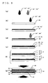
- a membrane and electrode assembly (MEA) 12 of the invention has catalyst layers 2 and 3 joined on both sides of a solid polymer electrolyte membrane 1 and thus has a sandwiched structure.
- at least one of the catalyst layers includes a polymer electrolyte and particles carrying a catalyst and a polymer electrolyte.
- the membrane and electrode assembly of the invention is characterized in that the proportion of a polymer electrolyte expressed by ⁇ (mass of polymer electrolyte)/(mass of particles in the particles carrying catalyst material) ⁇ is decreased toward the above polymer electrolyte membrane (the inside) from the surface of the catalyst layer (the outside).
- the structure of the surface of the catalyst layer (the outside) has a high proportion of the polymer electrolyte and thus a dense structure as compared with the catalyst layer positioned inside; the structure of the catalyst layer on the polymer electrolyte membrane side (the inside) has a low proportion of the polymer electrolyte and thus a sparse structure as compared with the catalyst layer positioned outside.
- the membrane and electrode assembly of the invention can be made to be a membrane and electrode assembly, which is a catalyst layer of a multilayered structure, produced by laminating two or more layers having different proportions of polymer electrolytes expressed by ⁇ (mass of polymer electrolyte)/(mass of particles in the particles carrying catalyst material) ⁇ in the catalyst layer, as shown in Fig. 1(a) .
- the catalyst layers positioned inside to the polymer electrolyte membrane 1 are catalyst layers 2a and 3a having low proportion of the polymer electrolyte as compared with the catalyst layers positioned outside (the surface of the membrane and electrode assembly 12) to the polymer electrolyte membrane 1.
- the catalyst layers positioned on the surface (the outside) are catalyst layers 2b and 3 b having a high proportion of the polymer electrolyte as compared with the catalyst layers positioned inside.
- the membrane and electrolyte assemblies of the invention include a membrane and electrode assembly comprising catalyst layers the proportion of the polymer electrolyte of which, expressed by ⁇ (mass of polymer electrolyte)/(mass of particles in the particles carrying catalyst material) ⁇ , is continuously decreased in the thickness direction toward the above polymer electrolyte membrane (the inside) from the surface of the catalyst layer (the outside).
- the catalyst layer positioned inside to the polymer electrolyte membrane 1 is a catalyst layer having a low proportion of the polymer electrolyte as compared with the catalyst layer positioned outside (the surface of the membrane and electrode assembly 12) to the polymer electrolyte membrane 1.
- the catalyst layer positioned on the surface (the outside) is a catalyst layer having a high proportion of the polymer electrolyte as compared with the catalyst layer positioned inside.
- the proportion of the polymer electrolyte in the thickness direction of the catalyst layer is changed to thereby change the catalyst layer to a sparse structure from a dense structure in the thickness direction toward the polymer electrolyte membrane (the inside) from the surface of the catalyst layer (the outside).
- This makes it possible to improve the water holding properties of the catalyst layer without inhibiting the diffusibility of the reactant gas, the removal of the water generated by the electrode reaction, etc. That is, ample water can be secured to produce a membrane and electrode assembly comprising high power generation characteristics even under low humidified conditions while preventing flooding.
- a decrease in power generation characteristics due to an increase in interface resistance is not recognized differently than the application of conventional humidity controlling membranes or the handling to low humidification by formation of grooves to the surface of the catalyst layer and the polymer electrolyte membrane fuel cell comprising the inventive membrane and electrode assembly has a remarkable effect of offering high power generation characteristics even under low humidified conditions as compared with the polymer electrolyte membrane fuel cell comprising the conventional membrane and electrode assembly.
- the value produced by dividing the highest value of the proportion of the polymer electrolyte in the thickness direction of the catalyst layer by the lowest value of the proportion of the above polymer electrolyte in the thickness direction of the catalyst layer is preferably within the range of from 1.2 to 5.0 both inclusive.
- the layer thickness of the catalyst layer 2a having a low proportion of the polymer electrolyte is preferably larger than the layer thickness of the catalyst layer 2b having a high proportion of the polymer electrolyte.
- the layer thickness of the catalyst layer 2a having a low proportion of the polymer electrolyte is made larger than the layer thickness of the catalyst layer 2b having a high proportion of the polymer electrolyte to thereby be able to suitably hold both the drainage of water generated by electrode reaction and water holding properties under low humidified conditions.
- the value obtained by dividing a high value of the proportion of the polymer electrolyte by a low value of the proportion of the polymer electrolyte among the proportions of the polymer electrolyte expressed by ⁇ (mass of polymer electrolyte)/(mass of particles in the particles carrying catalyst material) ⁇ when the catalyst layer is divided into two equivalents in the thickness direction is preferably within the range of from 1.2 to 5.0 both inclusive.
- Fig. 2 showed an exploded schematic diagram of the inventive polymer electrolyte membrane fuel cell.
- cathode side gas diffusion layer 4 and anode side gas diffusion layer 5 are disposed so as to face the catalyst layer 2 and the catalyst layer 3 of the membrane and electrode assembly 12. This each constitutes cathode 6 and anode 7.
- a pair of separators 10 made of a conductive and impermeable material comprising a gas passage 8 for gas circulation and a cooling water passage 9 for cooling water circulation in a principal plane opposing the gas passage are disposed.
- hydrogen gas is fed as a fuel gas from the gas passage 8 of the separator 10 on the anode 7 side.
- an oxygen-containing gas is fed as an oxidant gas from the gas passage 8 of the separator 10 on the cathode 6 side.
- an electromotive force can be generated between the anode and the cathode by causing electrode reaction between hydrogen as a fuel gas and oxygen gas in the presence of a catalyst.
- polymer electrolyte membrane fuel cell shown in Fig. 2 is a so-called single cell structure in which the solid polymer electrolyte membrane 1, catalyst layers 2 and 3, and gas diffusion layers 4 and 5 are sandwiched between a pair of separators, in the present invention, a plurality of cells can be laminated via the separator 10 to produce a fuel cell.
- a catalyst layer may be acceptable in which only in one catalyst layer, the proportion of the polymer electrolyte expressed by ⁇ (mass of polymer electrolyte)/(mass of particles in the particles carrying catalyst material) ⁇ is decreased toward the above polymer electrolyte membrane (the inside) from the surface of the catalyst layer (the outside).
- the catalyst layer in which the proportion of the polymer electrolyte is decreased toward the above polymer electrolyte membrane, which is on the inside, from the surface of the catalyst layer, which is on the outside is disposed on the cathode in which water is generated by electrode reaction.
- the membrane and electrode assembly comprising the catalyst layer in which the proportion of the polymer electrolyte expressed by ⁇ (mass of polymer electrolyte)/(mass of particles in the particles carrying catalyst material) ⁇ is decreased toward the above polymer electrolyte membrane (the inside) from the surface of the catalyst layer (the outside) may be easily produced by steps (1) to (3) below.
- step (1) is a step of producing at least two kinds of catalyst inks 2a", 2b", 3a" and 3b" having different proportions of the polymer electrolyte that are catalyst inks produced by dispersing particles carrying a catalyst material and a polymer electrolyte in a solvent ( Fig. 3(a) ).
- the catalyst ink is prepared by dispersing particles carrying a catalyst material and a polymer electrolyte in a solvent.
- the catalyst inks 2a" and 3a" having a high proportion of the polymer electrolyte and the catalyst inks 2b" and 3b" having a low proportion of the polymer electrolyte are produced ( Fig. 3(a) ).
- step (2) is a step of sequentially using a catalyst ink having a high proportion of the polymer electrolyte to a catalyst ink having a low proportion of the polymer electrolyte, applying them onto the substrate and drying the inks and forming on the above substrate a catalyst layer of a multilayered structure in which the above volumes of fine pores are sequentially changed ( Figs. 3(b) to 3(f) ).
- the catalyst inks 2a" and 3a" having a high proportion of the polymer electrolyte are applied onto a substrate 22 to form coating films 2a' and 3a' on the substrate 22 ( Figs. 3(b) and 3(c) ).
- a drying step is optionally provided, the solvent in the coating films is removed, and catalyst layers 2a and 3a having a high proportion of the polymer electrolyte are formed on the substrate 22.
- the catalyst inks 2b" and 3b" having a low proportion of the polymer electrolyte are applied onto the catalyst layers 2a and 3a having the high proportion of the polymer electrolyte ( Fig.
- a gas diffusion layer or a transfer sheet is used as the substrate.
- a catalyst ink having a high proportion of the polymer electrolyte and a catalyst ink having a low proportion of the polymer electrolyte are applied.
- the catalyst layer to be formed is made a multilayered structure, and the catalyst layer having a high proportion of the polymer electrolyte, i.e., having a dense structure, and the catalyst layer having a low proportion of the polymer electrolyte, i.e., having a sparse structure, to be formed in order from the substrate, are formed on the gas diffusion layer or transfer sheet.
- a membrane and electrode assembly can be produced that comprises a catalyst layer in which the proportion of the polymer electrolyte is increased toward the polymer electrolyte membrane (the inside) from the surface of the above catalyst layer (the outside), that is, a catalyst layer that is changed to a sparse structure from a dense structure, toward the polymer electrolyte membrane (the inside) from the surface of the above catalyst layer (the outside).
- a drying step of removing a solvent within the coating film is disposed as required.
- a catalyst ink for a first layer is applied onto the substrate to form a coating film and then the coating film is dried to form a catalyst layer for a first layer
- a catalyst ink for a second layer is applied onto the catalyst layer for the first layer and then the coating film is dried to form a catalyst layer for a second layer to thereby form a catalyst layer having a multilayered structure.
- a catalyst ink for a first layer is applied to form a coating film and a drying step is not carried out and subsequently a catalyst ink for a second layer is applied to form a coating film and these coating films are dried to thereby form a catalyst layer having a multilayered structure. It is possible as well that a catalyst ink for a first layer is applied to form a coating film and the coating film is dried and part of the solvent is left within the coating film to make semi-dry conditions and then a catalyst ink for a second layer is applied to form a coating film and these coating films are dried to form a catalyst layer having a multilayered structure. In the first method of producing the membrane and electrode assembly, a dry step of drying a coating film can be optionally changed.
- step (3) is a step of joining the above catalyst layer formed on the above substrate to the above polymer electrolyte membrane ( Fig. 3(e) ).
- the joining method can use hot press (hot pressing).
- hot press hot pressing
- the substrate is peeled after transfer by hot press, or when a gas diffusion layer is used as the substrate, the substrate is not peeled.
- the membrane and electrode assembly of the invention is produced by the first method of producing the membrane and electrode assembly as described above, the membrane and electrode assembly comprising a catalyst layer in which the proportion of the polymer electrolyte expressed by ⁇ (mass of polymer electrolyte)/(mass of particles in the particles carrying catalyst material) ⁇ is decreased toward the above polymer electrolyte membrane (the inside) from the surface of the catalyst layer (the outside).
- the first method of producing the membrane and electrode assembly of the invention can also use a polymer electrolyte membrane as the substrate and directly apply a catalyst ink to both sides of the polymer electrolyte membrane to form the membrane and electrode assembly.
- electrode catalyst inks are applied to the polymer electrolyte membrane in the order of decreasing proportion of the polymer electrolyte of the catalyst layers to be formed to thereby form a catalyst layer.
- the membrane and electrode assembly of the invention is produced that comprises a catalyst layer in which the proportion of the polymer electrolyte expressed by ⁇ (mass of polymer electrolyte)/(mass of particles in the particles carrying catalyst material) ⁇ is decreased toward the above polymer electrolyte membrane (the inside) from the surface of the catalyst layer (the outside).
- the first method of producing the membrane and electrode assembly includes forming a catalyst layer with a multilayered structure on a transfer sheet by use of the transfer sheet as the substrate, transferring the catalyst layer on the transfer sheet to a gas diffusion layer once and then joining the catalyst layer on the gas diffusion layer to the polymer electrolyte membrane to thereby form the membrane and electrode assembly.
- the catalyst layer formed on the transfer sheet (substrate) the catalyst layer having a low proportion of the polymer electrolyte and the catalyst layer having a high proportion of the polymer electrolyte are sequentially formed toward the surface of the catalyst layer from the substrate.
- the membrane and electrode assembly comprising the catalyst layer in which the proportion of the polymer electrolyte expressed by ⁇ (mass of polymer electrolyte)/(mass of particles in the particles carrying catalyst material) ⁇ is decreased toward the above polymer electrolyte membrane (the inside) from the surface of the catalyst layer may be easily produced by steps (1) to (3) below.
- step (1) is a step for producing a catalyst ink obtained by dispersing particles carrying a catalyst material and a polymer electrolyte in a solvent ( Fig. 4(a) ).
- Catalyst inks 2" and 3" are prepared by dispersing particles carrying a catalyst material and a polymer electrolyte in a solvent.
- step (2) is a step for applying the above catalyst ink onto the substrate to form a coating film, drying the coating film and removing the solvent within the coating film to form a catalyst layer, and also a step for giving a temperature to the opposite face of the coating film of the substrate higher than a temperature to the face of the coating film of the substrate in the thickness direction of the coating film when the coating film formed on the substrate is dried and the solvent is removed ( Fig. 4(b) and 4(c) ).
- the catalyst inks 2" and 3" containing particles carrying a catalyst material, a polymer electrolyte and a solvent are applied to the substrate ( Fig. 4(b) ). Then, coating films 2' and 3' on the substrate are placed over a cooling stage 23 equipped with a cooling mechanism 24 and the entire material including the cooling stage 23 is dried within an oven 25 to give a temperature difference to the coating film comprising the catalyst inks in the thickness direction ( Fig. 4(c) ). The coating films 2' and 3' are given a temperature higher on the side opposite to the substrate than on the substrate side.
- the solvent is removed and a catalyst layer is formed while a temperature difference is given to the coating film formed on the substrate in the thickness direction, whereby the proportion of the polymer electrolyte in the thickness direction of the catalyst layer is changed.
- a catalyst layer can be formed in which the proportion of the polymer electrolyte is decreased toward the surface opposite to the substrate from the substrate side.
- a transfer sheet or a gas diffusion layer can be used as the substrate.
- a membrane and electrode assembly can be produced that comprises a catalyst layer in which the proportion of the polymer electrolyte is increased toward the polymer electrolyte membrane (the inside) from the surface of the above catalyst layer (the outside), that is, a catalyst layer that is changed to a sparse structure from a dense structure, toward the polymer electrolyte membrane (the inside) from the surface of the above catalyst layer (the outside).
- the method of drying a coating film while giving a temperature difference in the thickness direction to the coating film to be formed on the substrate is not limited to the case in Fig. 3(c) , and for example, a method can be used that involves placing a substrate on which a coating film has been formed over a cooling stag, applying warm air to the coating film surface to dry while giving a temperature difference in the thickness direction.
- the cooling mechanism 24 of the cooling stage 23 can use, but is not limited to, a mechanism in which a cooling medium is passed in the stage by piping.
- step (3) is a step of joining the above catalyst layer formed on the above substrate to the above polymer electrolyte membrane ( Fig. 3(e) ).
- the joining method can use hot press (hot pressing).
- hot press hot pressing
- the substrate is peeled after joining by hot press.
- gas diffusion layer is used as the substrate, the substrate is not peeled.
- the temperature given to the surface opposite to the substrate of the coating film is preferably [(temperature given to substrate side) + 5°C] or higher and 150°C or lower.
- the temperature given to the coating film of the substrate side is lowered, the evaporation rate of the solvent is small and the catalyst layer having a finer pore volume is formed, so that water holding properties under low humidified conditions can be improved.
- the temperature given to the coating film of the substrate side is preferably 0°C or higher from the viewpoint of easy temperature control.
- the temperatures given to the substrate side of the coating film and to the side opposite to the substrate are preferably below the boiling point of the solvent. When the temperature given to the coating film is higher than the boiling point of the solvent, the evaporation rate remarkably becomes large, the catalyst layer in which the proportion of the polymer electrolyte in the thickness direction is changed may not be formed.
- the cooling stage is preferably used.
- the removal of the solvent within the coating film of the catalyst ink is initiated immediately after the application of the catalyst ink onto the substrate and also when the catalyst ink is applied onto the substrate to be coated, the cooling stage is preferably used.
- the membrane and electrode assembly of the invention is produced by the second method of producing the membrane and electrode assembly as described above, the membrane and electrode assembly comprising a catalyst layer in which the proportion of the polymer electrolyte expressed by ⁇ (mass of polymer electrolyte)/(mass of particles in the particles carrying catalyst material) ⁇ is decreased toward the above polymer electrolyte membrane (the inside) from the surface of the catalyst layer (the outside).
- the assembly can also produced by a method other than the first and second manufacturing methods.
- a combination of the first and second manufacturing methods may form the catalyst layer and may produce the membrane and electrode assembly.
- the polymer electrolyte membrane used for the membrane and electrode assembly and the fuel cell of the invention suitably have proton conductivity and can use fluorine polymer electrolytes and hydrocarbon polymer electrolytes.
- fluorine polymer electrolyte for example, Nafion (registered trademark) available from Du Pont Corp., Flemion (registered trademark) available from Asahi Glass Co., Ltd., Aciplex (registered trademark) available from Asahi Kasei Corporation, Gore Select (registered trademark) available from Gore Corp. or the like.
- Hydrocarbon polymer electrolyte membranes that can be used include electrolyte membranes such as sulfonated polyether ketone, sulfonated polyethersulfone, sulfonated polyether ether sulfone, sulfonated polysulfide, sulfonated polyphenylene.
- electrolyte membranes such as sulfonated polyether ketone, sulfonated polyethersulfone, sulfonated polyether ether sulfone, sulfonated polysulfide, sulfonated polyphenylene.
- Nafion (registered trademark) material available from Du Pont Corp. can be suitably used as the polymer electrolyte membrane.
- Hydrocarbon polymer electrolyte membranes that can be used include electrolyte membranes such as sulfonated polyether ketone, sulfonated polyethersulfone, sulfonated polyether ether sulfone, sulfonated polysulfide and sulfonated polyphenylene.
- the catalyst layers formed on both sides of the polymer electrolyte membrane are formed on both sides of the polymer electrolyte membrane using an electrode catalyst ink.
- the electrode catalyst ink includes at least a polymer electrolyte and a solvent.
- the polymer electrolyte contained in the inventive catalyst ink may suitably exhibit proton conductivity, and materials similar to the polymer electrolyte membrane can be used.
- Fluorine polymer electrolytes and hydrocarbon polymer electrolytes can be used.
- the fluorine polymer electrolytes that can be used include, for example, Nafion (registered trademark) materials available from Du Pont Corp.
- Hydrocarbon polymer electrolyte membranes that can be used also include electrolyte membranes such as sulfonated polyether ketone, sulfonated polyethersulfone, sulfonated polyether ether sulfone, sulfonated polysulfide and sulfonated polyphenylene.
- Nafion (registered trademark) material available from Du Pont Corp. can be suitably used as the polymer electrolyte membrane.
- materials equivalent to the polymer electrolyte membranes are preferably used.
- the catalyst materials that can be used in the invention include, in addition to the platinum group elements such as platinum and palladium, ruthenium, iridium, rhodium and osmium, metals such as iron, lead, copper, chromium, cobalt, nickel, manganese, vanadium, molybdenum, gallium and aluminum, alloys thereof, or oxides, complex oxides, and the like. Additionally, when the particle diameters of these catalysts are too large, the activity of the catalysts decreases, and when the diameter is too small, the stability is decreased, so it is preferably from 0.5 to 20 nm. More preferably, the diameter may be from 1 to 5 nm.
- the electrode reaction is excellent and efficiently carried out and the polymer electrolyte membrane fuel cell comprising the catalyst layer of the invention exhibits high power generation characteristics, whereby they are preferably used in the invention.
- the electron conductive powders carrying these catalysts generally make use of carbon particles. Any kinds of carbon particles are acceptable so long as they are particulate, exhibit conductivity and are not attacked by the catalyst, and the carbon particles that can be used include carbon black, graphite, black lead, activated charcoal, carbon fiber, carbon nanotube and fullerene. If the particle diameter of the carbon particle is too small, the electron conductive path is hardly formed and if the diameter is too large, the gas diffusibility of the catalyst layer is decreased or the utilization factor of the catalyst is lowered, so that the particle diameter is preferably about 10 to about 1,000 nm. The diameter is more preferably from 10 to 100 nm.
- the solvent used as a dispersing medium of the catalyst ink is not particularly limited so long as the solvent does not erode the catalyst particles and the polymer electrolyte and dissolves the polymer electrolyte in a high flowability state or disperses the polymer electrolyte as a fine gel.
- a volatile liquid organic solvent is desirably at least contained and the examples that are used include, but are not limited to, alcohols such as methanol, ethanol, 1-propanol, 2-propanol, 1-butanol, 2-butanol, isobutylalcohol, tert-butylalcohol and pentanol, ketones such as acetone, methyl ethyl ketone, pentanone, methyl isobutyl ketone, heptanone, cycrohexanone, methylcyclohexanone, acetonylacetone and di-isobutyl ketone, ethers such as tetrahydrofuran, dioxane, diethylene glycol dimethyl ether, anisole, methoxytoluene and dibutyl ether, and in addition polar solvents such as dimethylformamide, dimethylacetamide, N-methylpyrrolidone, ethylene glycol, diethylene glycol,
- a mixed solvent with water may be preferably selected when such solvent is used.
- the solvent may also contain water compatible with polymer electrolytes. The amount of addition of water is not particularly limited so long as the polymer electrolyte dissociates and generates cloudiness or is gelated.
- the catalyst ink may include a dispersing agent in order to disperse carbon particles carrying a catalyst material.
- the dispersing agents can include anionic surfactants, cationic surfactants, ampholytic surfactants, nonionic surfactants, and the like.
- the above anionic surfactants include, specifically, for example, carboxylic acid-type surfactants such as alkyl ether carboxylate salts, ether carboxylate salts, alkanoyl sarcosine, alkanoyl glutamate salts, acyl glutamate, oleic acid/N-methylic taurine, potassium oleate/diethanolamine salts, alkyl ether sulfate/triethanolamine salts, polyoxyethylene alkyl ether sulfate/triethanolamine salts, amine salts of specifically modified polyether-ester acids, amine salts of higher fatty acid derivatives, amine salts of specifically modified polyester acids, amine salts of high molecular weight polyether ester acids, amine salts of specifically modified phosphate esters, high-molecular weight polyester acid amide amine salts, specific fatty acid derivative amide amine salts, alkylamine salts of higher fatty acids, amide amine salts of high molecular weight poly
- the above cationic surfactants include, specifically for example, benzyldimethyl ⁇ 2-[2-(P-1,1,3,3-tetrametylbutylphenoxy)ethoxy]ethyl ⁇ ammonium chloride, octadecylamine acetate salts, tetradecylamine acetate salts, octadecyl trimethylammonium chloride, beef tallow trimethylammonium chloride, dodecyl trimethylammonium chloride, coconut trimethylammonium chloride, hexadecyltrimethylammonium chloride, behenyltrimethylammonium chloride, coco dimethyl benzyl ammonium chloride, tetradecyldimethylbenzylammonium chloride, octadecyldimethylbenzylammonium chloride, dioleyldimethylammonium chloride, 1-hydroxyethyl-2-beef tallow imidazoline
- ampholytic surfactants include, specifically for example, dimethyl palm betaine, dimethyl lauryl betaine, sodium lauryl aminoethyl glycine, sodium lauryl aminopropionate, stearyl dimethyl betaine, lauryl dihydroxyethyl betaine, amide betaines, imidazolinium betaine, lecithins, sodium 3-[ ⁇ -fluoroalkanoyl-N-ethylamino]-1-propanesulfonate, and N-[3-(perfluorooctanesulfoneamide)propyl]-N,N-dimethyl-N-carboxymethylene ammonium betaine.
- nonionic surfactants include, specifically for example, coconut fatty acid diethanolamide (1:2 type), coconut fatty acid diethanolamide (1:1 type), beef tallow acid diethanolamide (1:2 type), beef tallow acid diethanolamide (1:1 type), diethanolamide oleate (1:1 type), hydroxyethyl laurylamine, polyethylene glycol lauryl amine, polyethylene glycol cocoamine, polyethylene glycol stearylamine, polyethylene glycol beef tallow amines, polyethylene glycol beef tallow propylenediamines, polyethylene glycol dioleylamine, dimethyl laurylamine oxide, dimethyl stearylamine oxide, dihydroxyethyl laurylamine oxide, perfluoroalkylamine oxides, polyvinylpyrrolidones, higher alcohol ethylene oxide addition products, alkylphenylethylene oxide addition products, fatty acid ethylene oxide addition products, polypropylene glycol ethylene oxide addition products, fatty acid esters of glycerin,
- sulfonic acid type surfactants such as alkylbenzene sulfonic acids, oil-soluble alkylbenzene sulfonic acids, ⁇ -olefin sulfonic acids, sodium alkylbenzene sulfonates, oil-soluble alkylbenzenesulfonate salts, and ⁇ -olefin sulfonate salts are suitable in consideration of the diffusion effect of carbon, changes in catalyst performance due to the remaining of a dispersing agent, etc.
- Distributed processing is optionally carried out on the catalyst ink.
- the viscosity of the catalyst ink and the size of the particles can be controlled according to the conditions of distributed processing of the catalyst ink.
- Distributed processing can be conducted using various devices. Examples of distributed processing include processing by ball mills and roll mills, processing by shearing mills, processing by wet mills, ultrasonic dispersion processing, and other processing.
- homogenizers that perform agitation by centrifugal force and the like may be used.
- the solid matter includes carbon particles carrying a catalyst material (hereinafter, called a catalyst-carrying carbon) and a polymer electrolyte, and if the content of catalyst-carrying carbon is made large, the viscosity is increased even in the case of the same solid matter content, and if the catalyst-carrying carbon content is made small, the viscosity is decreased.
- a catalyst-carrying carbon a catalyst material
- polymer electrolyte a catalyst material
- the proportion of the catalyst-carrying carbon in the solid matter is preferably 10-80% by mass.
- the viscosity of the catalyst ink in this case is preferably from about 0.1 to about 500 cP, more preferably from 5 to 100 cP.
- the addition of a dispersing agent during catalyst ink dispersion enables the viscosity to be controlled.
- a pore-forming agent may also be included in the catalyst ink.
- the pore-forming agent is removed after the formation of a catalyst layer, thereby being capable of forming fine pores.
- the pore-forming agents include acids or alkalis, materials soluble in water, materials that sublime such as camphor, materials subjected to pyrolysis, and the like. If the material is soluble in warm water, it may be removed by the water generated during power generation.
- the pore-forming agents that are soluble in acids and alkalis and water include acid-soluble inorganic salts such as calcium carbonate, barium carbonate, magnesium carbonate, magnesium sulfate and magnesium oxide; inorganic salts that are soluble in aqueous alkaline solutions such as alumina, silica gels and silica sols; metals that are soluble in acids or alkalis such as aluminum, zinc, tin, nickel and iron; water-soluble inorganic salts such as sodium chloride, potassium chloride, ammonium chloride, sodium carbonate, sodium sulfate and monosodium phosphate; water-soluble organic compounds such as polyvinyl alcohols and polyethylene glycol; and the like. These can also be effectively used in combination of two or more species.
- acid-soluble inorganic salts such as calcium carbonate, barium carbonate, magnesium carbonate, magnesium sulfate and magnesium oxide
- inorganic salts that are soluble in aqueous alkaline solutions such as alumina,
- a gas diffusion layer, a transfer sheet or a polymer electrolyte membrane can be used as a substrate in the method of manufacturing the membrane and electrode assembly of the present invention.
- the catalyst ink is applied onto a substrate and forms a catalyst layer through the drying step.
- a gas diffusion layer or transfer sheet is used as the substrate, the catalyst layer is joined on both sides of the polymer electrolyte membrane by a joining step.
- a polymer electrolyte membrane is used as the substrate and a catalyst ink is directly applied onto both sides of the polymer electrolyte membrane to thereby be able to directly form a catalyst layer on both sides of the polymer electrolyte membrane.
- the application methods that are usable include a doctor blade method, dipping method, screen printing method, roll coating method, spraying method, and the like.
- a spraying method such as a pressure-spraying method, ultrasonic spraying method, or electrostatic spraying method hardly causes the agglomeration of the catalyst-carrying carbon when the coated catalyst ink is dried, thereby being capable of obtaining a homogeneous catalyst layer with high porosity.
- the transfer sheet used as the substrate is acceptable when having good transcription and the examples include fluorine-based resins such as ethylene tetrafluoroethylene copolymer (ETFE), tetrafluoroethylene-hexafluoropropylene copolymer (FEP), tetrafluoro perfluoroalkylvinyl ether copolymer (PFA) and polytetrafluoroethylene (PTFE).
- fluorine-based resins such as ethylene tetrafluoroethylene copolymer (ETFE), tetrafluoroethylene-hexafluoropropylene copolymer (FEP), tetrafluoro perfluoroalkylvinyl ether copolymer (PFA) and polytetrafluoroethylene (PTFE).
- polymer sheets and polymer films of polyimide, polyethylene terephthalate, polyamide (nylon), polysulfones, polyether sulphones, polyphenylene sulfides, polyether/ether ketones, polyether imides, polyarylates and polyethylene naphthalates, and the like can be used as the transfer sheets.
- the catalyst layer is joined to the polymer electrolyte membrane and then the transfer sheet is peeled to thereby form a membrane and electrode assembly (MEA) comprising the catalyst layer on both sides of the polymer electrolyte membrane.
- MEA membrane and electrode assembly
- the gas diffusion layer can utilize a material having gas diffusibility and conductivity.
- the gas diffusion layer can use porous carbon materials such as carbon cloth, carbon paper and nonwoven fabric.
- the gas diffusion layer can also be used as the substrate. In this case, the substrate, which is the gas diffusion layer, does not need to be peeled after the transfer step.
- a filling layer may be formed in advance on the gas diffusion layer.
- the filling layer prevents the catalyst ink from soaking into the gas diffusion layer, and the catalyst ink deposits on the filling layer to form a three-phase interface even when the amount of coating of the catalyst ink is small.
- Such a filling layer can be formed by dispersing carbon particles in a fluorine-based resin solution and sintering the resulting solution at a temperature higher than the melting point of the fluorine-based resin.
- Polytetrafluoroethylene (PTFE) or the like can be utilized as the fluorine-based resin.
- the separator In addition, a carbon type, metal type, or the like can be used as the separator. Additionally, the gas diffusion layer and the separator may become an integral structure. Moreover, when the separator or the catalyst layer has the function of the gas diffusion layer, the gas diffusion layer may be omitted. Furthermore, the fuel cell can be produced by assembling other attendant equipment such as a gas supply device and a cooling device.
- Platinum loaded carbon catalyst in which 50 wt% of platinum is included (product trade name: TEC10E50E, made by Tanaka Kikinzoku Kogyo K.K.) and 20 wt% of polymer electrolyte solution (Nafion (a registered trademark) by DuPont) were mixed in a solvent and a dispersing treatment was performed by a planetary ball mill (product name: Pulverisette 7, made by FRITSCH GmbH) for 30 minutes to obtain catalyst inks.
- a starting material having a composition ratio of platinum-carrying carbon to Nafion (registered trademark, made by Du Pont Corp.) being 2:1 (in terms of mass) was represented by catalyst ink 1A.
- a material having a mass ratio of 4:1 was represented by catalyst ink 1B.
- the solvent was made to have a volume ratio of 1-propanol to 2-propanol being 1:1.
- the content of solid matter was set to be 10% by mass.
- a polytetrafluoroethylene (PTFE) sheet was used as the transfer sheet.
- Catalyst ink 1A was applied onto the substrate with a doctor blade and the coating was dried for 5 minutes. Then, catalyst ink 1B was similarly applied thereonto, and the coating was dried at 90°C for 30 minutes in the atmosphere to produce a catalyst layer having a two-layer structure.
- the amounts of application of catalyst ink 1A and catalyst ink 1B per unit area were in a ratio of 1:5 in terms of mass.
- the thickness of the catalyst layer was adjusted in such a way that 0.3 mg/cm 2 of platinum was loaded in the electrode catalyst layer.
- Catalyst ink 1A was applied onto the substrate with a doctor blade and the coating was dried for 5 minutes. Then, the same catalyst ink 1A was applied thereonto again, and the coating was dried at 90°C for 30 minutes in the atmosphere to produce a catalyst layer. The ratio of the first and second coatings was 1:5 in mass. The thickness of the catalyst layer was adjusted in such a way that 0.3 mg/cm 2 of platinum was loaded in the electrode catalyst layer.
- the substrates having formed thereon the catalyst layers produced in Example 1 and Comparative Example 1 were each stamped into a square of 25cm 2 , and transfer sheets were disposed so as to face both sides of the polymer electrolyte membrane (Nafion (registered trademark name), made by Du Pont Corp.) and the resulting laminate was subjected to hot press at 130°C and 6.0 ⁇ 10 6 Pa to obtain a membrane and electrode assembly (MEA) illustrated in Fig. 1 .
- the polymer electrolyte membrane Nafion (registered trademark name), made by Du Pont Corp.
- the catalyst layer disposed on the substrate prior to transferring the catalyst layer to the polymer electrolyte membrane was subjected to surface observation.
- the catalyst layer disposed on the substrate after transferring the catalyst layer to the polymer electrolyte membrane was subjected to surface observation.
- Fig. 5 shows a scanning electron microscope (SEM) photograph of the surface of the catalyst layer, touched to the polymer electrolyte membrane, of the membrane and electrode assembly fabricated in Example 1.
- Fig. 6 shows a scanning electron microscope (SEM) photograph of the surface of the catalyst layer, opposite to the polymer electrolyte membrane, of the membrane and electrode assembly fabricated in Example 1.
- the surface shapes and the concentrations of the polymer electrolyte of the catalyst layers, on the polymer electrolyte membrane and opposite to the polymer electrolyte membrane (surface side), of the catalyst layer produced in Example 1 were observed to be greatly different from each other, as seen from Figs. 5 and 6 .
- the catalyst layers produced in Comparative Example 1 were similarly observed and the surface shapes of the catalyst layers, on and opposite to the polymer electrolyte membrane, were not greatly different as compared with Example 1.
- Fig. 7 The power generation characteristics of the membrane and electrolyte assemblies (MEA) produced in Example 1 and Comparative Example 1 are illustrated in Fig. 7 .
- the bold solid line (Example 1) indicates a power generation characteristic in low humidification of the membrane and electrode assembly
- the bold dotted line (Example 1) indicates a power generation characteristic in full humidification of the membrane and electrode assembly.
- the thin solid line shows a power generation characteristic in low humidification of the membrane and electrode assembly of Comparative Example 1
- the thin dotted line shows a power generation characteristic in full humidification of the membrane and electrode assembly of Comparative Example 1.
- the results of the power generation characteristics of the membrane and electrolyte assemblies of Example 1 and Comparative Example 1 have ascertained that the membrane and electrode assembly in which the volume of fine pores of the catalyst layer is increased in the thickness direction toward the above polymer electrolyte membrane from the vicinity of the gas diffusion layer exhibits improved water holding properties of the catalyst layer and its power generation characteristic in low humidification is shown to be equivalent to the power generation characteristic in full humidification.
- the results of the power generation characteristics of the membrane and electrolyte assemblies of Example 1 and Comparative Example 1 have ascertained that the membrane and electrode assembly of Example 1 improves water holding properties without inhibiting removal performance of the water generated by the electrode reaction and its power generation characteristic in low humidification is indicated to be equivalent to that in full humidification.
- Example 2 and Comparative Example 2 will be described.
- a platinum-carrying carbon catalyst having an amount of platinum carried of 50% by mass (Brand name: TEC10E50E, made by Tanaka Kikinzoku Kogyo) was mixed with 20% by mass of a polymer electrolyte solution (Nafion: registered trademark, made by Du Pont Corp.) in a solvent and the resulting mixture was dispersed by a planet-type ball mill (Brand name: Pulverisette7, made by Fritsch GmbH). The pot and the ball of the ball mill used were made from zirconia.
- a starting material having a composition ratio of platinum-carrying carbon to a polymer electrolyte (Nafion: registered trademark, made by Du Pont Corp.) being 2:1 (in terms of mass) was represented by catalyst ink 2.
- the solvent was made to have a volume ratio of 1-propanol to 2-propanol being 1:1. Moreover, the content of solid matter was set to be 10% by mass.
- a polytetrafluoroethylene (PTFE) sheet was used as the transfer sheet.
- the substrate was fixed on a cooling plate in which water at 20°C was circulated and the catalyst ink was applied onto the substrate with a doctor blade and then the substrate was dried for 30 minutes within an oven set at 80°C while the substrate was cooled at 20°C using the cooling plate to produce a catalyst layer.
- the thickness of the catalyst layer was adjusted such that the amount of platinum carried was about 0.3 mg/cm 2 .
- the catalyst ink described in Example 2 was used.
- the substrate described in Example 2 was used.
- the substrate was fixed on an aluminum plate (5 mm in thickness) that readily follows temperature change and dried at 80°C for 30 minutes in the atmosphere to produce a catalyst layer.
- the thickness of the catalyst layer was adjusted such that the amount of platinum carried was about 0.3 mg/cm 2 .
- the substrates having formed thereon the catalyst layers produced in Example 2 and Comparative Example 2 were each stamped into a square of 25 cm 2 , and transfer sheets were disposed so as to face both sides of the polymer electrolyte membrane (Nafion (registered trademark name), made by Du Pont Corp.) and the resulting laminate was subjected to hot press at 130°C and 6.0 ⁇ 10 6 Pa to obtain a membrane and electrode assembly (MEA) illustrated in Fig. 1 .
- the polymer electrolyte membrane Nafion (registered trademark name), made by Du Pont Corp.
- the catalyst layer disposed on the substrate prior to transferring the catalyst layer to the polymer electrolyte membrane was subjected to surface observation.
- the catalyst layer disposed on the substrate after transferring the catalyst layer to the polymer electrolyte membrane was subjected to surface observation.
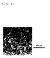
- the cross-sectional shape of the cross section of the catalyst layer was observed together.
- Fig. 8 shows a scanning electron microscope (SEM) photograph of the surface of the catalyst layer, touched to the polymer electrolyte membrane, of the membrane and electrode assembly fabricated in Example 2.
- Fig. 9 shows a scanning electron microscope (SEM) photograph of the surface of the catalyst layer (opposite to the polymer electrolyte membrane) of the membrane and electrode assembly fabricated in Example 2.
- Fig. 10 shows a scanning electron microscope (SEM) photograph of the vicinity of the cross section of the catalyst layer, on the polymer electrolyte membrane, of the membrane and electrode assembly fabricated in Example 2.
- Fig. 11 shows a scanning electron microscope (SEM) photograph of a vicinity of the cross section of the catalyst layer (opposite to the polymer electrolyte membrane) of the membrane and electrode assembly fabricated in Example 2.
- the catalyst layer of the membrane and electrode assembly fabricated in Example 2 was divided into two in the thickness direction and the amount of sulfur (S) was analyzed by an ICP mass spectroscope.
- S sulfur
- Fig. 12 The power generation characteristics of the membrane and electrolyte assemblies (MEA) produced in Example 2 and Comparative Example 2 are illustrated in Fig. 12 .
- the bold solid line (Example 2) indicates a power generation characteristic in low humidification of the membrane and electrode assembly
- the bold dotted line (Example 2) indicates a power generation characteristic in full humidification of the membrane and electrode assembly.
- the thin solid line shows a power generation characteristic in low humidification of the membrane and electrode assembly of Comparative Example 2
- the thin dotted line shows a power generation characteristic in full humidification of the membrane and electrode assembly of Comparative Example 2.
- the results of the power generation characteristics of the membrane and electrolyte assemblies of Example 2 and Comparative Example 2 have ascertained that the membrane and electrode assembly in which the proportion of the polymer electrolyte of the catalyst layer is decreased in the thickness direction toward the above polymer electrolyte membrane from the vicinity of the gas diffusion layer exhibits improved water holding properties of the catalyst layer and its power generation characteristic in low humidification is shown to be equivalent to the power generation characteristic in full humidification.
- the results of the power generation characteristics of the membrane and electrolyte assemblies of Example 2 and Comparative Example 2 have ascertained that the membrane and electrode assembly of Example 2 improves water holding properties without inhibiting removal performance of the water generated by the electrode reaction and its power generation characteristic in low humidification is indicated to be equivalent to that in full humidification.
- the membrane and electrode assembly of the present invention is produced by sandwiching a polymer electrolyte membrane between a pair of catalyst layers, the catalyst layer comprising a polymer electrolyte and particles carrying a catalyst material, in which the proportion of the polymer electrolyte expressed by ⁇ (mass of polymer electrolyte)/(mass of particles in particles carrying catalyst material) ⁇ is decreased toward the above polymer electrolyte membrane (the inside) from the surface of the catalyst layer (the outside).
- the structure of the catalyst layer is changed to a sparse structure from a dense structure, toward the polymer electrolyte membrane from the surface side, can increase the water holding properties of the catalyst layer without inhibiting the diffusibility of reaction gas, the removal for the water generated by the electrode reaction, etc.
Landscapes
- Chemical & Material Sciences (AREA)
- Chemical Kinetics & Catalysis (AREA)
- General Chemical & Material Sciences (AREA)
- Electrochemistry (AREA)
- Engineering & Computer Science (AREA)
- Manufacturing & Machinery (AREA)
- Materials Engineering (AREA)
- Physics & Mathematics (AREA)
- Thermal Sciences (AREA)
- Life Sciences & Earth Sciences (AREA)
- Sustainable Development (AREA)
- Sustainable Energy (AREA)
- Inert Electrodes (AREA)
- Fuel Cell (AREA)
Applications Claiming Priority (3)
| Application Number | Priority Date | Filing Date | Title |
|---|---|---|---|
| JP2007172630 | 2007-06-29 | ||
| JP2007172637 | 2007-06-29 | ||
| PCT/JP2008/061513 WO2009004958A1 (fr) | 2007-06-29 | 2008-06-25 | Ensemble électrode à membrane, procédé de production dudit ensemble électrode à membrane et pile à combustible à électrolyte polymère solide |
Publications (3)
| Publication Number | Publication Date |
|---|---|
| EP2164122A1 true EP2164122A1 (fr) | 2010-03-17 |
| EP2164122A4 EP2164122A4 (fr) | 2013-01-30 |
| EP2164122B1 EP2164122B1 (fr) | 2018-10-31 |
Family
ID=40226005
Family Applications (1)
| Application Number | Title | Priority Date | Filing Date |
|---|---|---|---|
| EP08777570.6A Not-in-force EP2164122B1 (fr) | 2007-06-29 | 2008-06-25 | Ensemble électrode à membrane et procédé de production dudit ensemble électrode à membrane |
Country Status (6)
| Country | Link |
|---|---|
| US (1) | US8614028B2 (fr) |
| EP (1) | EP2164122B1 (fr) |
| JP (1) | JP5397221B2 (fr) |
| KR (1) | KR101537425B1 (fr) |
| CN (1) | CN101816086B (fr) |
| WO (1) | WO2009004958A1 (fr) |
Cited By (2)
| Publication number | Priority date | Publication date | Assignee | Title |
|---|---|---|---|---|
| EP2398101A1 (fr) * | 2010-06-17 | 2011-12-21 | Bayer MaterialScience AG | Electrode de diffusion gazeuse et méthode de fabrication |
| WO2021175479A1 (fr) * | 2020-03-06 | 2021-09-10 | Audi Ag | Procédé de production de pile à combustible, dispositif de production d'agencement de membrane-électrode pour pile à combustible, pile à combustible et empilement de piles à combustible |
Families Citing this family (8)
| Publication number | Priority date | Publication date | Assignee | Title |
|---|---|---|---|---|
| JP2009289623A (ja) * | 2008-05-29 | 2009-12-10 | Toyota Motor Corp | 膜電極接合体における触媒層の製造方法 |
| JP5515902B2 (ja) * | 2010-03-17 | 2014-06-11 | 凸版印刷株式会社 | 固体高分子形燃料電池、膜・電極接合体、電極触媒層、及びその製造方法 |
| US8940461B2 (en) * | 2010-03-25 | 2015-01-27 | GM Global Technology Operations LLC | Method for membrane electrode assembly fabrication and membrane electrode assembly |
| USD633731S1 (en) | 2010-07-09 | 2011-03-08 | Hartley & Marks Publishers, Inc. | Display stand |
| JP6571961B2 (ja) * | 2015-03-25 | 2019-09-04 | 株式会社東芝 | 燃料電池用電極、燃料電池用膜電極複合体および燃料電池 |
| CN115298862A (zh) * | 2020-03-27 | 2022-11-04 | 三井金属矿业株式会社 | 电化学电池用电极催化剂层、电化学电池用膜电极接合体及电化学电池 |
| WO2021257711A1 (fr) * | 2020-06-16 | 2021-12-23 | The Government Of The United States Of America, As Represented By The Secretary Of The Navy | Ensemble électrode-membrane à interfaces multiples |
| CN114725402A (zh) * | 2022-04-08 | 2022-07-08 | 安徽枡水新能源科技有限公司 | 一种制备燃料电池催化剂涂布浆料的制备方法及其应用 |
Citations (4)
| Publication number | Priority date | Publication date | Assignee | Title |
|---|---|---|---|---|
| US4804592A (en) * | 1987-10-16 | 1989-02-14 | The United States Of America As Represented By The United States Department Of Energy | Composite electrode for use in electrochemical cells |
| EP1705737A1 (fr) * | 2004-01-26 | 2006-09-27 | Matsushita Electric Industrial Co., Ltd. | Ensemble couches de catalyseur a membrane, ensemble electrodes a membrane et pile a combustible a electrolyte polymere |
| US20070078051A1 (en) * | 2005-09-30 | 2007-04-05 | Honda Motor Co., Ltd. | Method for manufacturing electrode layer for fuel cell |
| WO2007048612A2 (fr) * | 2005-10-27 | 2007-05-03 | Ird Fuel Cells A/S | Ensembles d'electrodes a membrane destine a des piles a combustible a methanol direct et a hydrogene d'electrolyte polymere et procedes de production de ceux-ci |
Family Cites Families (17)
| Publication number | Priority date | Publication date | Assignee | Title |
|---|---|---|---|---|
| JP3326254B2 (ja) * | 1993-11-09 | 2002-09-17 | 株式会社豊田中央研究所 | 燃料電池 |
| JP3555196B2 (ja) * | 1994-09-19 | 2004-08-18 | トヨタ自動車株式会社 | 燃料電池とその製造方法 |
| JPH08162123A (ja) * | 1994-12-05 | 1996-06-21 | Tanaka Kikinzoku Kogyo Kk | 高分子電解質型電気化学セル及びその製造方法 |
| KR100437293B1 (ko) | 1999-09-21 | 2004-06-25 | 마쯔시다덴기산교 가부시키가이샤 | 고분자 전해질형 연료전지 및 그 제조방법 |
| JP2005056583A (ja) | 2002-07-09 | 2005-03-03 | Matsushita Electric Ind Co Ltd | 燃料電池用電解質膜電極接合体、それを用いた燃料電池およびその製造方法 |
| US20040058227A1 (en) | 2002-07-09 | 2004-03-25 | Matsushita Electric Industrial Co., Ltd. | Electrolyte membrane-electrode assembly for a fuel cell, fuel cell using the same and method of making the same |
| JP4400177B2 (ja) | 2003-10-31 | 2010-01-20 | 株式会社ジーエス・ユアサコーポレーション | 燃料電池用電極 |
| JP3732213B2 (ja) | 2004-01-26 | 2006-01-05 | 松下電器産業株式会社 | 膜触媒層接合体、膜電極接合体および高分子電解質形燃料電池 |
| JP2006087651A (ja) | 2004-09-24 | 2006-04-06 | Matsushita Electric Works Ltd | 風呂ふた |
| JP4190478B2 (ja) | 2004-10-22 | 2008-12-03 | 本田技研工業株式会社 | 固体高分子型燃料電池 |
| JP2006164790A (ja) * | 2004-12-08 | 2006-06-22 | Nissan Motor Co Ltd | 燃料電池用触媒層の形成装置及び燃料電池用触媒層の形成方法 |
| JP4837298B2 (ja) | 2005-03-10 | 2011-12-14 | 日本ゴア株式会社 | 湿度調整フィルム |
| US20090269653A1 (en) * | 2005-03-28 | 2009-10-29 | Kabushiki Kaisha Toshiba | Fuel cell |
| JP5013740B2 (ja) | 2005-04-28 | 2012-08-29 | キヤノン株式会社 | 固体高分子型燃料電池の疎水性触媒層及びその製造方法、固体高分子型燃料電池及びその製造方法 |
| JP2007080726A (ja) | 2005-09-15 | 2007-03-29 | Jsr Corp | 電極−膜接合体 |
| JP2007141588A (ja) | 2005-11-17 | 2007-06-07 | Nissan Motor Co Ltd | 燃料電池用膜電極接合体およびこれを用いた固体高分子形燃料電池 |
| JP2008186798A (ja) | 2007-01-31 | 2008-08-14 | Nissan Motor Co Ltd | 電解質膜−電極接合体 |
-
2008
- 2008-06-25 KR KR1020107002125A patent/KR101537425B1/ko active IP Right Grant
- 2008-06-25 JP JP2009521588A patent/JP5397221B2/ja active Active
- 2008-06-25 WO PCT/JP2008/061513 patent/WO2009004958A1/fr active Application Filing
- 2008-06-25 US US12/666,898 patent/US8614028B2/en not_active Expired - Fee Related
- 2008-06-25 EP EP08777570.6A patent/EP2164122B1/fr not_active Not-in-force
- 2008-06-25 CN CN200880105547.0A patent/CN101816086B/zh not_active Expired - Fee Related
Patent Citations (4)
| Publication number | Priority date | Publication date | Assignee | Title |
|---|---|---|---|---|
| US4804592A (en) * | 1987-10-16 | 1989-02-14 | The United States Of America As Represented By The United States Department Of Energy | Composite electrode for use in electrochemical cells |
| EP1705737A1 (fr) * | 2004-01-26 | 2006-09-27 | Matsushita Electric Industrial Co., Ltd. | Ensemble couches de catalyseur a membrane, ensemble electrodes a membrane et pile a combustible a electrolyte polymere |
| US20070078051A1 (en) * | 2005-09-30 | 2007-04-05 | Honda Motor Co., Ltd. | Method for manufacturing electrode layer for fuel cell |
| WO2007048612A2 (fr) * | 2005-10-27 | 2007-05-03 | Ird Fuel Cells A/S | Ensembles d'electrodes a membrane destine a des piles a combustible a methanol direct et a hydrogene d'electrolyte polymere et procedes de production de ceux-ci |
Non-Patent Citations (1)
| Title |
|---|
| See also references of WO2009004958A1 * |
Cited By (3)
| Publication number | Priority date | Publication date | Assignee | Title |
|---|---|---|---|---|
| EP2398101A1 (fr) * | 2010-06-17 | 2011-12-21 | Bayer MaterialScience AG | Electrode de diffusion gazeuse et méthode de fabrication |
| US10224552B2 (en) | 2010-06-17 | 2019-03-05 | Covestro Ag | Gas diffusion electrode and process for production thereof |
| WO2021175479A1 (fr) * | 2020-03-06 | 2021-09-10 | Audi Ag | Procédé de production de pile à combustible, dispositif de production d'agencement de membrane-électrode pour pile à combustible, pile à combustible et empilement de piles à combustible |
Also Published As
| Publication number | Publication date |
|---|---|
| US8614028B2 (en) | 2013-12-24 |
| WO2009004958A1 (fr) | 2009-01-08 |
| JP5397221B2 (ja) | 2014-01-22 |
| KR101537425B1 (ko) | 2015-07-16 |
| JPWO2009004958A1 (ja) | 2010-08-26 |
| CN101816086A (zh) | 2010-08-25 |
| EP2164122B1 (fr) | 2018-10-31 |
| CN101816086B (zh) | 2014-06-04 |
| US20100261089A1 (en) | 2010-10-14 |
| KR20100036357A (ko) | 2010-04-07 |
| EP2164122A4 (fr) | 2013-01-30 |
Similar Documents
| Publication | Publication Date | Title |
|---|---|---|
| US7947411B1 (en) | Membrane and electrode assembly and method of producing the same, and polymer electrolyte membrane fuel cell | |
| US8614028B2 (en) | Membrane and electrode assembly and method of producing the same, and polymer electrolyte membrane fuel cell | |
| JP2009218006A (ja) | 電解質膜−電極接合体の製造方法 | |
| JP5321003B2 (ja) | 膜電極接合体の製造方法 | |
| JP2010067493A (ja) | 膜電極接合体の製造方法、膜電極接合体、固体高分子形燃料電池 | |
| US20120183878A1 (en) | Manufacturing Method Of Electrode Catalyst Layer, Electrode Catalyst Layer, Membrane Electrode Assembly And Fuel Cell | |
| US11817607B2 (en) | Membrane electrode assembly and polymer electrolyte fuel cell | |
| CN100377401C (zh) | 催化剂层形成用墨、使用该墨的电极及膜电极接合体 | |
| JP5332444B2 (ja) | 膜電極接合体及びその製造方法、固体高分子形燃料電池 | |
| JP5998934B2 (ja) | 燃料電池用電極触媒層の製造方法、燃料電池用膜電極接合体、固体高分子形燃料電池 | |
| JP2014007099A (ja) | 燃料電池用電極触媒層およびその製造方法 | |
| JP2013073892A (ja) | 燃料電池用膜電極接合体の製造方法 | |
| JP6984317B2 (ja) | 燃料電池用膜電極接合体及びその製造方法、並びに固体高分子形燃料電池 | |
| JP7069686B2 (ja) | 膜電極接合体及び固体高分子形燃料電池 | |
| JP2017117751A (ja) | 膜電極接合体の製造方法及び膜電極接合体、並びに固体高分子形燃料電池 | |
| JP6862827B2 (ja) | 燃料電池用電極触媒層およびその製造方法 | |
| JP5964549B2 (ja) | 燃料電池用電極触媒層の製造方法ならびに燃料電池用電極触媒層、燃料電池用膜電極接合体および固体高分子形燃料電池 | |
| JP2010062062A (ja) | 膜電極接合体の製造方法、膜電極接合体、固体高分子型燃料電池 | |
| JP2017054670A (ja) | 膜電極接合体の製造方法及び膜電極接合体、並びに固体高分子形燃料電池 | |
| JP2021027048A (ja) | 燃料電池用膜電極接合体及び固体高分子形燃料電池 | |
| JP2021027049A (ja) | 燃料電池用膜電極接合体及び固体高分子形燃料電池 | |
| JP6160164B2 (ja) | 燃料電池用電極の製造方法、及び燃料電池用膜電極接合体の製造法 | |
| JP2020173935A (ja) | 燃料電池用膜電極接合体及び固体高分子形燃料電池 | |
| JP2020061248A (ja) | 燃料電池用膜電極接合体及び固体高分子形燃料電池 | |
| JP2020061247A (ja) | 燃料電池用膜電極接合体及び固体高分子形燃料電池 |
Legal Events
| Date | Code | Title | Description |
|---|---|---|---|
| PUAI | Public reference made under article 153(3) epc to a published international application that has entered the european phase |
Free format text: ORIGINAL CODE: 0009012 |
|
| 17P | Request for examination filed |
Effective date: 20100129 |
|
| AK | Designated contracting states |
Kind code of ref document: A1 Designated state(s): AT BE BG CH CY CZ DE DK EE ES FI FR GB GR HR HU IE IS IT LI LT LU LV MC MT NL NO PL PT RO SE SI SK TR |
|
| AX | Request for extension of the european patent |
Extension state: AL BA MK RS |
|
| DAX | Request for extension of the european patent (deleted) | ||
| A4 | Supplementary search report drawn up and despatched |
Effective date: 20130107 |
|
| RIC1 | Information provided on ipc code assigned before grant |
Ipc: H01M 4/86 20060101AFI20121221BHEP Ipc: H01M 8/02 20060101ALI20121221BHEP Ipc: H01M 8/10 20060101ALI20121221BHEP Ipc: H01M 4/92 20060101ALI20121221BHEP Ipc: H01M 4/88 20060101ALI20121221BHEP |
|
| 17Q | First examination report despatched |
Effective date: 20160317 |
|
| STAA | Information on the status of an ep patent application or granted ep patent |
Free format text: STATUS: EXAMINATION IS IN PROGRESS |
|
| RIC1 | Information provided on ipc code assigned before grant |
Ipc: H01M 4/88 20060101ALI20180410BHEP Ipc: H01M 8/1004 20160101ALI20180410BHEP Ipc: H01M 4/86 20060101AFI20180410BHEP Ipc: H01M 4/92 20060101ALI20180410BHEP |
|
| GRAP | Despatch of communication of intention to grant a patent |
Free format text: ORIGINAL CODE: EPIDOSNIGR1 |
|
| STAA | Information on the status of an ep patent application or granted ep patent |
Free format text: STATUS: GRANT OF PATENT IS INTENDED |
|
| INTG | Intention to grant announced |
Effective date: 20180607 |
|
| GRAS | Grant fee paid |
Free format text: ORIGINAL CODE: EPIDOSNIGR3 |
|
| GRAA | (expected) grant |
Free format text: ORIGINAL CODE: 0009210 |
|
| STAA | Information on the status of an ep patent application or granted ep patent |
Free format text: STATUS: THE PATENT HAS BEEN GRANTED |
|
| AK | Designated contracting states |
Kind code of ref document: B1 Designated state(s): AT BE BG CH CY CZ DE DK EE ES FI FR GB GR HR HU IE IS IT LI LT LU LV MC MT NL NO PL PT RO SE SI SK TR |
|
| REG | Reference to a national code |
Ref country code: CH Ref legal event code: EP Ref country code: GB Ref legal event code: FG4D |
|
| REG | Reference to a national code |
Ref country code: AT Ref legal event code: REF Ref document number: 1060487 Country of ref document: AT Kind code of ref document: T Effective date: 20181115 |
|
| REG | Reference to a national code |
Ref country code: DE Ref legal event code: R096 Ref document number: 602008057705 Country of ref document: DE |
|
| REG | Reference to a national code |
Ref country code: IE Ref legal event code: FG4D |
|
| REG | Reference to a national code |
Ref country code: NL Ref legal event code: MP Effective date: 20181031 |
|
| REG | Reference to a national code |
Ref country code: LT Ref legal event code: MG4D |
|
| REG | Reference to a national code |
Ref country code: AT Ref legal event code: MK05 Ref document number: 1060487 Country of ref document: AT Kind code of ref document: T Effective date: 20181031 |
|
| PG25 | Lapsed in a contracting state [announced via postgrant information from national office to epo] |
Ref country code: IS Free format text: LAPSE BECAUSE OF FAILURE TO SUBMIT A TRANSLATION OF THE DESCRIPTION OR TO PAY THE FEE WITHIN THE PRESCRIBED TIME-LIMIT Effective date: 20190228 Ref country code: LV Free format text: LAPSE BECAUSE OF FAILURE TO SUBMIT A TRANSLATION OF THE DESCRIPTION OR TO PAY THE FEE WITHIN THE PRESCRIBED TIME-LIMIT Effective date: 20181031 Ref country code: FI Free format text: LAPSE BECAUSE OF FAILURE TO SUBMIT A TRANSLATION OF THE DESCRIPTION OR TO PAY THE FEE WITHIN THE PRESCRIBED TIME-LIMIT Effective date: 20181031 Ref country code: NO Free format text: LAPSE BECAUSE OF FAILURE TO SUBMIT A TRANSLATION OF THE DESCRIPTION OR TO PAY THE FEE WITHIN THE PRESCRIBED TIME-LIMIT Effective date: 20190131 Ref country code: LT Free format text: LAPSE BECAUSE OF FAILURE TO SUBMIT A TRANSLATION OF THE DESCRIPTION OR TO PAY THE FEE WITHIN THE PRESCRIBED TIME-LIMIT Effective date: 20181031 Ref country code: BG Free format text: LAPSE BECAUSE OF FAILURE TO SUBMIT A TRANSLATION OF THE DESCRIPTION OR TO PAY THE FEE WITHIN THE PRESCRIBED TIME-LIMIT Effective date: 20190131 Ref country code: PL Free format text: LAPSE BECAUSE OF FAILURE TO SUBMIT A TRANSLATION OF THE DESCRIPTION OR TO PAY THE FEE WITHIN THE PRESCRIBED TIME-LIMIT Effective date: 20181031 Ref country code: AT Free format text: LAPSE BECAUSE OF FAILURE TO SUBMIT A TRANSLATION OF THE DESCRIPTION OR TO PAY THE FEE WITHIN THE PRESCRIBED TIME-LIMIT Effective date: 20181031 Ref country code: HR Free format text: LAPSE BECAUSE OF FAILURE TO SUBMIT A TRANSLATION OF THE DESCRIPTION OR TO PAY THE FEE WITHIN THE PRESCRIBED TIME-LIMIT Effective date: 20181031 Ref country code: ES Free format text: LAPSE BECAUSE OF FAILURE TO SUBMIT A TRANSLATION OF THE DESCRIPTION OR TO PAY THE FEE WITHIN THE PRESCRIBED TIME-LIMIT Effective date: 20181031 |
|
| PG25 | Lapsed in a contracting state [announced via postgrant information from national office to epo] |
Ref country code: SE Free format text: LAPSE BECAUSE OF FAILURE TO SUBMIT A TRANSLATION OF THE DESCRIPTION OR TO PAY THE FEE WITHIN THE PRESCRIBED TIME-LIMIT Effective date: 20181031 Ref country code: PT Free format text: LAPSE BECAUSE OF FAILURE TO SUBMIT A TRANSLATION OF THE DESCRIPTION OR TO PAY THE FEE WITHIN THE PRESCRIBED TIME-LIMIT Effective date: 20190301 Ref country code: NL Free format text: LAPSE BECAUSE OF FAILURE TO SUBMIT A TRANSLATION OF THE DESCRIPTION OR TO PAY THE FEE WITHIN THE PRESCRIBED TIME-LIMIT Effective date: 20181031 Ref country code: GR Free format text: LAPSE BECAUSE OF FAILURE TO SUBMIT A TRANSLATION OF THE DESCRIPTION OR TO PAY THE FEE WITHIN THE PRESCRIBED TIME-LIMIT Effective date: 20190201 |
|
| PG25 | Lapsed in a contracting state [announced via postgrant information from national office to epo] |
Ref country code: CZ Free format text: LAPSE BECAUSE OF FAILURE TO SUBMIT A TRANSLATION OF THE DESCRIPTION OR TO PAY THE FEE WITHIN THE PRESCRIBED TIME-LIMIT Effective date: 20181031 Ref country code: IT Free format text: LAPSE BECAUSE OF FAILURE TO SUBMIT A TRANSLATION OF THE DESCRIPTION OR TO PAY THE FEE WITHIN THE PRESCRIBED TIME-LIMIT Effective date: 20181031 Ref country code: DK Free format text: LAPSE BECAUSE OF FAILURE TO SUBMIT A TRANSLATION OF THE DESCRIPTION OR TO PAY THE FEE WITHIN THE PRESCRIBED TIME-LIMIT Effective date: 20181031 |
|
| REG | Reference to a national code |
Ref country code: DE Ref legal event code: R097 Ref document number: 602008057705 Country of ref document: DE |
|
| PG25 | Lapsed in a contracting state [announced via postgrant information from national office to epo] |
Ref country code: SK Free format text: LAPSE BECAUSE OF FAILURE TO SUBMIT A TRANSLATION OF THE DESCRIPTION OR TO PAY THE FEE WITHIN THE PRESCRIBED TIME-LIMIT Effective date: 20181031 Ref country code: EE Free format text: LAPSE BECAUSE OF FAILURE TO SUBMIT A TRANSLATION OF THE DESCRIPTION OR TO PAY THE FEE WITHIN THE PRESCRIBED TIME-LIMIT Effective date: 20181031 Ref country code: RO Free format text: LAPSE BECAUSE OF FAILURE TO SUBMIT A TRANSLATION OF THE DESCRIPTION OR TO PAY THE FEE WITHIN THE PRESCRIBED TIME-LIMIT Effective date: 20181031 |
|
| PLBE | No opposition filed within time limit |
Free format text: ORIGINAL CODE: 0009261 |
|
| STAA | Information on the status of an ep patent application or granted ep patent |
Free format text: STATUS: NO OPPOSITION FILED WITHIN TIME LIMIT |
|
| 26N | No opposition filed |
Effective date: 20190801 |
|
| PG25 | Lapsed in a contracting state [announced via postgrant information from national office to epo] |
Ref country code: SI Free format text: LAPSE BECAUSE OF FAILURE TO SUBMIT A TRANSLATION OF THE DESCRIPTION OR TO PAY THE FEE WITHIN THE PRESCRIBED TIME-LIMIT Effective date: 20181031 |
|
| PG25 | Lapsed in a contracting state [announced via postgrant information from national office to epo] |
Ref country code: MC Free format text: LAPSE BECAUSE OF FAILURE TO SUBMIT A TRANSLATION OF THE DESCRIPTION OR TO PAY THE FEE WITHIN THE PRESCRIBED TIME-LIMIT Effective date: 20181031 |
|
| REG | Reference to a national code |
Ref country code: CH Ref legal event code: PL |
|
| REG | Reference to a national code |
Ref country code: BE Ref legal event code: MM Effective date: 20190630 |
|
| PG25 | Lapsed in a contracting state [announced via postgrant information from national office to epo] |
Ref country code: TR Free format text: LAPSE BECAUSE OF FAILURE TO SUBMIT A TRANSLATION OF THE DESCRIPTION OR TO PAY THE FEE WITHIN THE PRESCRIBED TIME-LIMIT Effective date: 20181031 |
|
| PG25 | Lapsed in a contracting state [announced via postgrant information from national office to epo] |
Ref country code: IE Free format text: LAPSE BECAUSE OF NON-PAYMENT OF DUE FEES Effective date: 20190625 |
|
| PG25 | Lapsed in a contracting state [announced via postgrant information from national office to epo] |
Ref country code: LI Free format text: LAPSE BECAUSE OF NON-PAYMENT OF DUE FEES Effective date: 20190630 Ref country code: BE Free format text: LAPSE BECAUSE OF NON-PAYMENT OF DUE FEES Effective date: 20190630 Ref country code: LU Free format text: LAPSE BECAUSE OF NON-PAYMENT OF DUE FEES Effective date: 20190625 Ref country code: CH Free format text: LAPSE BECAUSE OF NON-PAYMENT OF DUE FEES Effective date: 20190630 |
|
| PG25 | Lapsed in a contracting state [announced via postgrant information from national office to epo] |
Ref country code: FR Free format text: LAPSE BECAUSE OF NON-PAYMENT OF DUE FEES Effective date: 20190630 |
|
| PGFP | Annual fee paid to national office [announced via postgrant information from national office to epo] |
Ref country code: DE Payment date: 20200609 Year of fee payment: 13 |
|
| PGFP | Annual fee paid to national office [announced via postgrant information from national office to epo] |
Ref country code: GB Payment date: 20200618 Year of fee payment: 13 |
|
| PG25 | Lapsed in a contracting state [announced via postgrant information from national office to epo] |
Ref country code: CY Free format text: LAPSE BECAUSE OF FAILURE TO SUBMIT A TRANSLATION OF THE DESCRIPTION OR TO PAY THE FEE WITHIN THE PRESCRIBED TIME-LIMIT Effective date: 20181031 |
|
| PG25 | Lapsed in a contracting state [announced via postgrant information from national office to epo] |
Ref country code: HU Free format text: LAPSE BECAUSE OF FAILURE TO SUBMIT A TRANSLATION OF THE DESCRIPTION OR TO PAY THE FEE WITHIN THE PRESCRIBED TIME-LIMIT; INVALID AB INITIO Effective date: 20080625 Ref country code: MT Free format text: LAPSE BECAUSE OF FAILURE TO SUBMIT A TRANSLATION OF THE DESCRIPTION OR TO PAY THE FEE WITHIN THE PRESCRIBED TIME-LIMIT Effective date: 20181031 |
|
| REG | Reference to a national code |
Ref country code: DE Ref legal event code: R119 Ref document number: 602008057705 Country of ref document: DE |
|
| GBPC | Gb: european patent ceased through non-payment of renewal fee |
Effective date: 20210625 |
|
| PG25 | Lapsed in a contracting state [announced via postgrant information from national office to epo] |
Ref country code: GB Free format text: LAPSE BECAUSE OF NON-PAYMENT OF DUE FEES Effective date: 20210625 Ref country code: DE Free format text: LAPSE BECAUSE OF NON-PAYMENT OF DUE FEES Effective date: 20220101 |