EP2164098A1 - Boîtier semi-conducteur et procédé de fabrication correspondant - Google Patents
Boîtier semi-conducteur et procédé de fabrication correspondant Download PDFInfo
- Publication number
- EP2164098A1 EP2164098A1 EP08790715A EP08790715A EP2164098A1 EP 2164098 A1 EP2164098 A1 EP 2164098A1 EP 08790715 A EP08790715 A EP 08790715A EP 08790715 A EP08790715 A EP 08790715A EP 2164098 A1 EP2164098 A1 EP 2164098A1
- Authority
- EP
- European Patent Office
- Prior art keywords
- filter
- substrate
- semiconductor
- cap substrate
- spacer
- Prior art date
- Legal status (The legal status is an assumption and is not a legal conclusion. Google has not performed a legal analysis and makes no representation as to the accuracy of the status listed.)
- Withdrawn
Links
- 239000004065 semiconductor Substances 0.000 title claims abstract description 261
- 238000004519 manufacturing process Methods 0.000 title claims abstract description 44
- 238000000034 method Methods 0.000 title claims description 42
- 239000000758 substrate Substances 0.000 claims abstract description 266
- 125000006850 spacer group Chemical group 0.000 claims abstract description 72
- 230000035515 penetration Effects 0.000 claims description 44
- 229910000679 solder Inorganic materials 0.000 claims description 32
- 238000004299 exfoliation Methods 0.000 abstract description 20
- 239000011347 resin Substances 0.000 description 32
- 229920005989 resin Polymers 0.000 description 32
- 230000001681 protective effect Effects 0.000 description 23
- 230000008569 process Effects 0.000 description 17
- 239000000463 material Substances 0.000 description 12
- 230000003287 optical effect Effects 0.000 description 11
- 239000011521 glass Substances 0.000 description 9
- 238000009833 condensation Methods 0.000 description 7
- 230000005494 condensation Effects 0.000 description 7
- VYPSYNLAJGMNEJ-UHFFFAOYSA-N Silicium dioxide Chemical compound O=[Si]=O VYPSYNLAJGMNEJ-UHFFFAOYSA-N 0.000 description 6
- 230000015572 biosynthetic process Effects 0.000 description 6
- 230000008602 contraction Effects 0.000 description 6
- 238000005520 cutting process Methods 0.000 description 6
- 230000000694 effects Effects 0.000 description 6
- 230000035699 permeability Effects 0.000 description 6
- 238000001444 catalytic combustion detection Methods 0.000 description 5
- 229920001721 polyimide Polymers 0.000 description 5
- 239000000126 substance Substances 0.000 description 5
- 238000001354 calcination Methods 0.000 description 4
- 239000010949 copper Substances 0.000 description 4
- 239000002245 particle Substances 0.000 description 4
- 229910052681 coesite Inorganic materials 0.000 description 3
- 229910052906 cristobalite Inorganic materials 0.000 description 3
- 238000001035 drying Methods 0.000 description 3
- 238000005530 etching Methods 0.000 description 3
- 238000003384 imaging method Methods 0.000 description 3
- 239000002184 metal Substances 0.000 description 3
- 229910052751 metal Inorganic materials 0.000 description 3
- 239000009719 polyimide resin Substances 0.000 description 3
- 239000000377 silicon dioxide Substances 0.000 description 3
- 229910052682 stishovite Inorganic materials 0.000 description 3
- 229910052905 tridymite Inorganic materials 0.000 description 3
- CSCPPACGZOOCGX-UHFFFAOYSA-N Acetone Chemical compound CC(C)=O CSCPPACGZOOCGX-UHFFFAOYSA-N 0.000 description 2
- 239000004925 Acrylic resin Substances 0.000 description 2
- 229920000178 Acrylic resin Polymers 0.000 description 2
- 239000004642 Polyimide Substances 0.000 description 2
- 239000004372 Polyvinyl alcohol Substances 0.000 description 2
- XUIMIQQOPSSXEZ-UHFFFAOYSA-N Silicon Chemical compound [Si] XUIMIQQOPSSXEZ-UHFFFAOYSA-N 0.000 description 2
- GWEVSGVZZGPLCZ-UHFFFAOYSA-N Titan oxide Chemical compound O=[Ti]=O GWEVSGVZZGPLCZ-UHFFFAOYSA-N 0.000 description 2
- 229910045601 alloy Inorganic materials 0.000 description 2
- 239000000956 alloy Substances 0.000 description 2
- 238000004380 ashing Methods 0.000 description 2
- 238000001723 curing Methods 0.000 description 2
- 239000003822 epoxy resin Substances 0.000 description 2
- 238000007654 immersion Methods 0.000 description 2
- 238000005304 joining Methods 0.000 description 2
- 238000000206 photolithography Methods 0.000 description 2
- 239000000049 pigment Substances 0.000 description 2
- 229920000647 polyepoxide Polymers 0.000 description 2
- 229920002451 polyvinyl alcohol Polymers 0.000 description 2
- 239000002243 precursor Substances 0.000 description 2
- 229910052710 silicon Inorganic materials 0.000 description 2
- 239000010703 silicon Substances 0.000 description 2
- 229910052718 tin Inorganic materials 0.000 description 2
- 229910018182 Al—Cu Inorganic materials 0.000 description 1
- JBRZTFJDHDCESZ-UHFFFAOYSA-N AsGa Chemical compound [As]#[Ga] JBRZTFJDHDCESZ-UHFFFAOYSA-N 0.000 description 1
- RYGMFSIKBFXOCR-UHFFFAOYSA-N Copper Chemical compound [Cu] RYGMFSIKBFXOCR-UHFFFAOYSA-N 0.000 description 1
- 229910001218 Gallium arsenide Inorganic materials 0.000 description 1
- 206010034972 Photosensitivity reaction Diseases 0.000 description 1
- 229910018594 Si-Cu Inorganic materials 0.000 description 1
- 229910008465 Si—Cu Inorganic materials 0.000 description 1
- ATJFFYVFTNAWJD-UHFFFAOYSA-N Tin Chemical compound [Sn] ATJFFYVFTNAWJD-UHFFFAOYSA-N 0.000 description 1
- 238000003848 UV Light-Curing Methods 0.000 description 1
- 230000001133 acceleration Effects 0.000 description 1
- 229910052782 aluminium Inorganic materials 0.000 description 1
- 230000008901 benefit Effects 0.000 description 1
- 239000000919 ceramic Substances 0.000 description 1
- 238000001311 chemical methods and process Methods 0.000 description 1
- 230000000295 complement effect Effects 0.000 description 1
- 229910052802 copper Inorganic materials 0.000 description 1
- 238000004132 cross linking Methods 0.000 description 1
- 238000009713 electroplating Methods 0.000 description 1
- 229910052732 germanium Inorganic materials 0.000 description 1
- GNPVGFCGXDBREM-UHFFFAOYSA-N germanium atom Chemical compound [Ge] GNPVGFCGXDBREM-UHFFFAOYSA-N 0.000 description 1
- 229910052737 gold Inorganic materials 0.000 description 1
- 230000006872 improvement Effects 0.000 description 1
- 238000010030 laminating Methods 0.000 description 1
- 229910001635 magnesium fluoride Inorganic materials 0.000 description 1
- 230000007257 malfunction Effects 0.000 description 1
- 239000003960 organic solvent Substances 0.000 description 1
- 238000004806 packaging method and process Methods 0.000 description 1
- 239000003973 paint Substances 0.000 description 1
- 230000002093 peripheral effect Effects 0.000 description 1
- 239000005011 phenolic resin Substances 0.000 description 1
- 239000006089 photosensitive glass Substances 0.000 description 1
- 230000036211 photosensitivity Effects 0.000 description 1
- 238000001020 plasma etching Methods 0.000 description 1
- 238000000623 plasma-assisted chemical vapour deposition Methods 0.000 description 1
- KCTAWXVAICEBSD-UHFFFAOYSA-N prop-2-enoyloxy prop-2-eneperoxoate Chemical compound C=CC(=O)OOOC(=O)C=C KCTAWXVAICEBSD-UHFFFAOYSA-N 0.000 description 1
- 230000009467 reduction Effects 0.000 description 1
- 238000005476 soldering Methods 0.000 description 1
- 238000004544 sputter deposition Methods 0.000 description 1
- PBCFLUZVCVVTBY-UHFFFAOYSA-N tantalum pentoxide Inorganic materials O=[Ta](=O)O[Ta](=O)=O PBCFLUZVCVVTBY-UHFFFAOYSA-N 0.000 description 1
- 229920001187 thermosetting polymer Polymers 0.000 description 1
- 238000002834 transmittance Methods 0.000 description 1
- 238000007740 vapor deposition Methods 0.000 description 1
- 239000002966 varnish Substances 0.000 description 1
Images


Classifications
-
- H—ELECTRICITY
- H01—ELECTRIC ELEMENTS
- H01L—SEMICONDUCTOR DEVICES NOT COVERED BY CLASS H10
- H01L31/00—Semiconductor devices sensitive to infrared radiation, light, electromagnetic radiation of shorter wavelength or corpuscular radiation and specially adapted either for the conversion of the energy of such radiation into electrical energy or for the control of electrical energy by such radiation; Processes or apparatus specially adapted for the manufacture or treatment thereof or of parts thereof; Details thereof
- H01L31/02—Details
- H01L31/0203—Containers; Encapsulations, e.g. encapsulation of photodiodes
-
- H—ELECTRICITY
- H01—ELECTRIC ELEMENTS
- H01L—SEMICONDUCTOR DEVICES NOT COVERED BY CLASS H10
- H01L23/00—Details of semiconductor or other solid state devices
- H01L23/02—Containers; Seals
-
- H—ELECTRICITY
- H01—ELECTRIC ELEMENTS
- H01L—SEMICONDUCTOR DEVICES NOT COVERED BY CLASS H10
- H01L23/00—Details of semiconductor or other solid state devices
- H01L23/02—Containers; Seals
- H01L23/04—Containers; Seals characterised by the shape of the container or parts, e.g. caps, walls
- H01L23/053—Containers; Seals characterised by the shape of the container or parts, e.g. caps, walls the container being a hollow construction and having an insulating or insulated base as a mounting for the semiconductor body
- H01L23/055—Containers; Seals characterised by the shape of the container or parts, e.g. caps, walls the container being a hollow construction and having an insulating or insulated base as a mounting for the semiconductor body the leads having a passage through the base
-
- H—ELECTRICITY
- H01—ELECTRIC ELEMENTS
- H01L—SEMICONDUCTOR DEVICES NOT COVERED BY CLASS H10
- H01L23/00—Details of semiconductor or other solid state devices
- H01L23/12—Mountings, e.g. non-detachable insulating substrates
-
- H—ELECTRICITY
- H01—ELECTRIC ELEMENTS
- H01L—SEMICONDUCTOR DEVICES NOT COVERED BY CLASS H10
- H01L23/00—Details of semiconductor or other solid state devices
- H01L23/16—Fillings or auxiliary members in containers or encapsulations, e.g. centering rings
-
- H—ELECTRICITY
- H01—ELECTRIC ELEMENTS
- H01L—SEMICONDUCTOR DEVICES NOT COVERED BY CLASS H10
- H01L23/00—Details of semiconductor or other solid state devices
- H01L23/52—Arrangements for conducting electric current within the device in operation from one component to another, i.e. interconnections, e.g. wires, lead frames
- H01L23/538—Arrangements for conducting electric current within the device in operation from one component to another, i.e. interconnections, e.g. wires, lead frames the interconnection structure between a plurality of semiconductor chips being formed on, or in, insulating substrates
- H01L23/5389—Arrangements for conducting electric current within the device in operation from one component to another, i.e. interconnections, e.g. wires, lead frames the interconnection structure between a plurality of semiconductor chips being formed on, or in, insulating substrates the chips being integrally enclosed by the interconnect and support structures
-
- H—ELECTRICITY
- H01—ELECTRIC ELEMENTS
- H01L—SEMICONDUCTOR DEVICES NOT COVERED BY CLASS H10
- H01L24/00—Arrangements for connecting or disconnecting semiconductor or solid-state bodies; Methods or apparatus related thereto
- H01L24/01—Means for bonding being attached to, or being formed on, the surface to be connected, e.g. chip-to-package, die-attach, "first-level" interconnects; Manufacturing methods related thereto
- H01L24/18—High density interconnect [HDI] connectors; Manufacturing methods related thereto
- H01L24/19—Manufacturing methods of high density interconnect preforms
-
- H—ELECTRICITY
- H01—ELECTRIC ELEMENTS
- H01L—SEMICONDUCTOR DEVICES NOT COVERED BY CLASS H10
- H01L24/00—Arrangements for connecting or disconnecting semiconductor or solid-state bodies; Methods or apparatus related thereto
- H01L24/80—Methods for connecting semiconductor or other solid state bodies using means for bonding being attached to, or being formed on, the surface to be connected
- H01L24/82—Methods for connecting semiconductor or other solid state bodies using means for bonding being attached to, or being formed on, the surface to be connected by forming build-up interconnects at chip-level, e.g. for high density interconnects [HDI]
-
- H—ELECTRICITY
- H01—ELECTRIC ELEMENTS
- H01L—SEMICONDUCTOR DEVICES NOT COVERED BY CLASS H10
- H01L24/00—Arrangements for connecting or disconnecting semiconductor or solid-state bodies; Methods or apparatus related thereto
- H01L24/93—Batch processes
- H01L24/95—Batch processes at chip-level, i.e. with connecting carried out on a plurality of singulated devices, i.e. on diced chips
- H01L24/97—Batch processes at chip-level, i.e. with connecting carried out on a plurality of singulated devices, i.e. on diced chips the devices being connected to a common substrate, e.g. interposer, said common substrate being separable into individual assemblies after connecting
-
- H—ELECTRICITY
- H01—ELECTRIC ELEMENTS
- H01L—SEMICONDUCTOR DEVICES NOT COVERED BY CLASS H10
- H01L27/00—Devices consisting of a plurality of semiconductor or other solid-state components formed in or on a common substrate
- H01L27/14—Devices consisting of a plurality of semiconductor or other solid-state components formed in or on a common substrate including semiconductor components sensitive to infrared radiation, light, electromagnetic radiation of shorter wavelength or corpuscular radiation and specially adapted either for the conversion of the energy of such radiation into electrical energy or for the control of electrical energy by such radiation
- H01L27/144—Devices controlled by radiation
- H01L27/146—Imager structures
- H01L27/14601—Structural or functional details thereof
- H01L27/14618—Containers
-
- H—ELECTRICITY
- H01—ELECTRIC ELEMENTS
- H01L—SEMICONDUCTOR DEVICES NOT COVERED BY CLASS H10
- H01L27/00—Devices consisting of a plurality of semiconductor or other solid-state components formed in or on a common substrate
- H01L27/14—Devices consisting of a plurality of semiconductor or other solid-state components formed in or on a common substrate including semiconductor components sensitive to infrared radiation, light, electromagnetic radiation of shorter wavelength or corpuscular radiation and specially adapted either for the conversion of the energy of such radiation into electrical energy or for the control of electrical energy by such radiation
- H01L27/144—Devices controlled by radiation
- H01L27/146—Imager structures
- H01L27/14601—Structural or functional details thereof
- H01L27/1462—Coatings
- H01L27/14621—Colour filter arrangements
-
- H—ELECTRICITY
- H01—ELECTRIC ELEMENTS
- H01L—SEMICONDUCTOR DEVICES NOT COVERED BY CLASS H10
- H01L21/00—Processes or apparatus adapted for the manufacture or treatment of semiconductor or solid state devices or of parts thereof
- H01L21/02—Manufacture or treatment of semiconductor devices or of parts thereof
- H01L21/04—Manufacture or treatment of semiconductor devices or of parts thereof the devices having potential barriers, e.g. a PN junction, depletion layer or carrier concentration layer
- H01L21/50—Assembly of semiconductor devices using processes or apparatus not provided for in a single one of the subgroups H01L21/06 - H01L21/326, e.g. sealing of a cap to a base of a container
- H01L21/56—Encapsulations, e.g. encapsulation layers, coatings
- H01L21/568—Temporary substrate used as encapsulation process aid
-
- H—ELECTRICITY
- H01—ELECTRIC ELEMENTS
- H01L—SEMICONDUCTOR DEVICES NOT COVERED BY CLASS H10
- H01L2224/00—Indexing scheme for arrangements for connecting or disconnecting semiconductor or solid-state bodies and methods related thereto as covered by H01L24/00
- H01L2224/01—Means for bonding being attached to, or being formed on, the surface to be connected, e.g. chip-to-package, die-attach, "first-level" interconnects; Manufacturing methods related thereto
- H01L2224/02—Bonding areas; Manufacturing methods related thereto
- H01L2224/04—Structure, shape, material or disposition of the bonding areas prior to the connecting process
- H01L2224/04105—Bonding areas formed on an encapsulation of the semiconductor or solid-state body, e.g. bonding areas on chip-scale packages
-
- H—ELECTRICITY
- H01—ELECTRIC ELEMENTS
- H01L—SEMICONDUCTOR DEVICES NOT COVERED BY CLASS H10
- H01L2224/00—Indexing scheme for arrangements for connecting or disconnecting semiconductor or solid-state bodies and methods related thereto as covered by H01L24/00
- H01L2224/01—Means for bonding being attached to, or being formed on, the surface to be connected, e.g. chip-to-package, die-attach, "first-level" interconnects; Manufacturing methods related thereto
- H01L2224/10—Bump connectors; Manufacturing methods related thereto
- H01L2224/12—Structure, shape, material or disposition of the bump connectors prior to the connecting process
- H01L2224/12105—Bump connectors formed on an encapsulation of the semiconductor or solid-state body, e.g. bumps on chip-scale packages
-
- H—ELECTRICITY
- H01—ELECTRIC ELEMENTS
- H01L—SEMICONDUCTOR DEVICES NOT COVERED BY CLASS H10
- H01L2224/00—Indexing scheme for arrangements for connecting or disconnecting semiconductor or solid-state bodies and methods related thereto as covered by H01L24/00
- H01L2224/73—Means for bonding being of different types provided for in two or more of groups H01L2224/10, H01L2224/18, H01L2224/26, H01L2224/34, H01L2224/42, H01L2224/50, H01L2224/63, H01L2224/71
- H01L2224/732—Location after the connecting process
- H01L2224/73251—Location after the connecting process on different surfaces
- H01L2224/73267—Layer and HDI connectors
-
- H—ELECTRICITY
- H01—ELECTRIC ELEMENTS
- H01L—SEMICONDUCTOR DEVICES NOT COVERED BY CLASS H10
- H01L2224/00—Indexing scheme for arrangements for connecting or disconnecting semiconductor or solid-state bodies and methods related thereto as covered by H01L24/00
- H01L2224/91—Methods for connecting semiconductor or solid state bodies including different methods provided for in two or more of groups H01L2224/80 - H01L2224/90
- H01L2224/92—Specific sequence of method steps
- H01L2224/922—Connecting different surfaces of the semiconductor or solid-state body with connectors of different types
- H01L2224/9222—Sequential connecting processes
- H01L2224/92242—Sequential connecting processes the first connecting process involving a layer connector
- H01L2224/92244—Sequential connecting processes the first connecting process involving a layer connector the second connecting process involving a build-up interconnect
-
- H—ELECTRICITY
- H01—ELECTRIC ELEMENTS
- H01L—SEMICONDUCTOR DEVICES NOT COVERED BY CLASS H10
- H01L2224/00—Indexing scheme for arrangements for connecting or disconnecting semiconductor or solid-state bodies and methods related thereto as covered by H01L24/00
- H01L2224/93—Batch processes
- H01L2224/95—Batch processes at chip-level, i.e. with connecting carried out on a plurality of singulated devices, i.e. on diced chips
- H01L2224/97—Batch processes at chip-level, i.e. with connecting carried out on a plurality of singulated devices, i.e. on diced chips the devices being connected to a common substrate, e.g. interposer, said common substrate being separable into individual assemblies after connecting
-
- H—ELECTRICITY
- H01—ELECTRIC ELEMENTS
- H01L—SEMICONDUCTOR DEVICES NOT COVERED BY CLASS H10
- H01L23/00—Details of semiconductor or other solid state devices
- H01L23/48—Arrangements for conducting electric current to or from the solid state body in operation, e.g. leads, terminal arrangements ; Selection of materials therefor
- H01L23/488—Arrangements for conducting electric current to or from the solid state body in operation, e.g. leads, terminal arrangements ; Selection of materials therefor consisting of soldered or bonded constructions
- H01L23/498—Leads, i.e. metallisations or lead-frames on insulating substrates, e.g. chip carriers
- H01L23/49811—Additional leads joined to the metallisation on the insulating substrate, e.g. pins, bumps, wires, flat leads
- H01L23/49816—Spherical bumps on the substrate for external connection, e.g. ball grid arrays [BGA]
-
- H—ELECTRICITY
- H01—ELECTRIC ELEMENTS
- H01L—SEMICONDUCTOR DEVICES NOT COVERED BY CLASS H10
- H01L27/00—Devices consisting of a plurality of semiconductor or other solid-state components formed in or on a common substrate
- H01L27/14—Devices consisting of a plurality of semiconductor or other solid-state components formed in or on a common substrate including semiconductor components sensitive to infrared radiation, light, electromagnetic radiation of shorter wavelength or corpuscular radiation and specially adapted either for the conversion of the energy of such radiation into electrical energy or for the control of electrical energy by such radiation
- H01L27/144—Devices controlled by radiation
- H01L27/146—Imager structures
- H01L27/14683—Processes or apparatus peculiar to the manufacture or treatment of these devices or parts thereof
-
- H—ELECTRICITY
- H01—ELECTRIC ELEMENTS
- H01L—SEMICONDUCTOR DEVICES NOT COVERED BY CLASS H10
- H01L2924/00—Indexing scheme for arrangements or methods for connecting or disconnecting semiconductor or solid-state bodies as covered by H01L24/00
- H01L2924/01—Chemical elements
- H01L2924/01004—Beryllium [Be]
-
- H—ELECTRICITY
- H01—ELECTRIC ELEMENTS
- H01L—SEMICONDUCTOR DEVICES NOT COVERED BY CLASS H10
- H01L2924/00—Indexing scheme for arrangements or methods for connecting or disconnecting semiconductor or solid-state bodies as covered by H01L24/00
- H01L2924/01—Chemical elements
- H01L2924/01005—Boron [B]
-
- H—ELECTRICITY
- H01—ELECTRIC ELEMENTS
- H01L—SEMICONDUCTOR DEVICES NOT COVERED BY CLASS H10
- H01L2924/00—Indexing scheme for arrangements or methods for connecting or disconnecting semiconductor or solid-state bodies as covered by H01L24/00
- H01L2924/01—Chemical elements
- H01L2924/01006—Carbon [C]
-
- H—ELECTRICITY
- H01—ELECTRIC ELEMENTS
- H01L—SEMICONDUCTOR DEVICES NOT COVERED BY CLASS H10
- H01L2924/00—Indexing scheme for arrangements or methods for connecting or disconnecting semiconductor or solid-state bodies as covered by H01L24/00
- H01L2924/01—Chemical elements
- H01L2924/01013—Aluminum [Al]
-
- H—ELECTRICITY
- H01—ELECTRIC ELEMENTS
- H01L—SEMICONDUCTOR DEVICES NOT COVERED BY CLASS H10
- H01L2924/00—Indexing scheme for arrangements or methods for connecting or disconnecting semiconductor or solid-state bodies as covered by H01L24/00
- H01L2924/01—Chemical elements
- H01L2924/01029—Copper [Cu]
-
- H—ELECTRICITY
- H01—ELECTRIC ELEMENTS
- H01L—SEMICONDUCTOR DEVICES NOT COVERED BY CLASS H10
- H01L2924/00—Indexing scheme for arrangements or methods for connecting or disconnecting semiconductor or solid-state bodies as covered by H01L24/00
- H01L2924/01—Chemical elements
- H01L2924/01032—Germanium [Ge]
-
- H—ELECTRICITY
- H01—ELECTRIC ELEMENTS
- H01L—SEMICONDUCTOR DEVICES NOT COVERED BY CLASS H10
- H01L2924/00—Indexing scheme for arrangements or methods for connecting or disconnecting semiconductor or solid-state bodies as covered by H01L24/00
- H01L2924/01—Chemical elements
- H01L2924/01033—Arsenic [As]
-
- H—ELECTRICITY
- H01—ELECTRIC ELEMENTS
- H01L—SEMICONDUCTOR DEVICES NOT COVERED BY CLASS H10
- H01L2924/00—Indexing scheme for arrangements or methods for connecting or disconnecting semiconductor or solid-state bodies as covered by H01L24/00
- H01L2924/01—Chemical elements
- H01L2924/01047—Silver [Ag]
-
- H—ELECTRICITY
- H01—ELECTRIC ELEMENTS
- H01L—SEMICONDUCTOR DEVICES NOT COVERED BY CLASS H10
- H01L2924/00—Indexing scheme for arrangements or methods for connecting or disconnecting semiconductor or solid-state bodies as covered by H01L24/00
- H01L2924/01—Chemical elements
- H01L2924/0106—Neodymium [Nd]
-
- H—ELECTRICITY
- H01—ELECTRIC ELEMENTS
- H01L—SEMICONDUCTOR DEVICES NOT COVERED BY CLASS H10
- H01L2924/00—Indexing scheme for arrangements or methods for connecting or disconnecting semiconductor or solid-state bodies as covered by H01L24/00
- H01L2924/01—Chemical elements
- H01L2924/01073—Tantalum [Ta]
-
- H—ELECTRICITY
- H01—ELECTRIC ELEMENTS
- H01L—SEMICONDUCTOR DEVICES NOT COVERED BY CLASS H10
- H01L2924/00—Indexing scheme for arrangements or methods for connecting or disconnecting semiconductor or solid-state bodies as covered by H01L24/00
- H01L2924/01—Chemical elements
- H01L2924/01077—Iridium [Ir]
-
- H—ELECTRICITY
- H01—ELECTRIC ELEMENTS
- H01L—SEMICONDUCTOR DEVICES NOT COVERED BY CLASS H10
- H01L2924/00—Indexing scheme for arrangements or methods for connecting or disconnecting semiconductor or solid-state bodies as covered by H01L24/00
- H01L2924/01—Chemical elements
- H01L2924/01078—Platinum [Pt]
-
- H—ELECTRICITY
- H01—ELECTRIC ELEMENTS
- H01L—SEMICONDUCTOR DEVICES NOT COVERED BY CLASS H10
- H01L2924/00—Indexing scheme for arrangements or methods for connecting or disconnecting semiconductor or solid-state bodies as covered by H01L24/00
- H01L2924/01—Chemical elements
- H01L2924/01079—Gold [Au]
-
- H—ELECTRICITY
- H01—ELECTRIC ELEMENTS
- H01L—SEMICONDUCTOR DEVICES NOT COVERED BY CLASS H10
- H01L2924/00—Indexing scheme for arrangements or methods for connecting or disconnecting semiconductor or solid-state bodies as covered by H01L24/00
- H01L2924/01—Chemical elements
- H01L2924/01082—Lead [Pb]
-
- H—ELECTRICITY
- H01—ELECTRIC ELEMENTS
- H01L—SEMICONDUCTOR DEVICES NOT COVERED BY CLASS H10
- H01L2924/00—Indexing scheme for arrangements or methods for connecting or disconnecting semiconductor or solid-state bodies as covered by H01L24/00
- H01L2924/095—Indexing scheme for arrangements or methods for connecting or disconnecting semiconductor or solid-state bodies as covered by H01L24/00 with a principal constituent of the material being a combination of two or more materials provided in the groups H01L2924/013 - H01L2924/0715
- H01L2924/097—Glass-ceramics, e.g. devitrified glass
- H01L2924/09701—Low temperature co-fired ceramic [LTCC]
-
- H—ELECTRICITY
- H01—ELECTRIC ELEMENTS
- H01L—SEMICONDUCTOR DEVICES NOT COVERED BY CLASS H10
- H01L2924/00—Indexing scheme for arrangements or methods for connecting or disconnecting semiconductor or solid-state bodies as covered by H01L24/00
- H01L2924/10—Details of semiconductor or other solid state devices to be connected
- H01L2924/102—Material of the semiconductor or solid state bodies
- H01L2924/1025—Semiconducting materials
- H01L2924/1026—Compound semiconductors
- H01L2924/1032—III-V
- H01L2924/10329—Gallium arsenide [GaAs]
-
- H—ELECTRICITY
- H01—ELECTRIC ELEMENTS
- H01L—SEMICONDUCTOR DEVICES NOT COVERED BY CLASS H10
- H01L2924/00—Indexing scheme for arrangements or methods for connecting or disconnecting semiconductor or solid-state bodies as covered by H01L24/00
- H01L2924/10—Details of semiconductor or other solid state devices to be connected
- H01L2924/11—Device type
- H01L2924/14—Integrated circuits
-
- H—ELECTRICITY
- H01—ELECTRIC ELEMENTS
- H01L—SEMICONDUCTOR DEVICES NOT COVERED BY CLASS H10
- H01L2924/00—Indexing scheme for arrangements or methods for connecting or disconnecting semiconductor or solid-state bodies as covered by H01L24/00
- H01L2924/10—Details of semiconductor or other solid state devices to be connected
- H01L2924/146—Mixed devices
- H01L2924/1461—MEMS
-
- H—ELECTRICITY
- H01—ELECTRIC ELEMENTS
- H01L—SEMICONDUCTOR DEVICES NOT COVERED BY CLASS H10
- H01L2924/00—Indexing scheme for arrangements or methods for connecting or disconnecting semiconductor or solid-state bodies as covered by H01L24/00
- H01L2924/15—Details of package parts other than the semiconductor or other solid state devices to be connected
- H01L2924/151—Die mounting substrate
- H01L2924/156—Material
- H01L2924/15786—Material with a principal constituent of the material being a non metallic, non metalloid inorganic material
- H01L2924/15788—Glasses, e.g. amorphous oxides, nitrides or fluorides
-
- H—ELECTRICITY
- H01—ELECTRIC ELEMENTS
- H01L—SEMICONDUCTOR DEVICES NOT COVERED BY CLASS H10
- H01L2924/00—Indexing scheme for arrangements or methods for connecting or disconnecting semiconductor or solid-state bodies as covered by H01L24/00
- H01L2924/15—Details of package parts other than the semiconductor or other solid state devices to be connected
- H01L2924/181—Encapsulation
-
- H—ELECTRICITY
- H01—ELECTRIC ELEMENTS
- H01L—SEMICONDUCTOR DEVICES NOT COVERED BY CLASS H10
- H01L2924/00—Indexing scheme for arrangements or methods for connecting or disconnecting semiconductor or solid-state bodies as covered by H01L24/00
- H01L2924/30—Technical effects
- H01L2924/301—Electrical effects
- H01L2924/3025—Electromagnetic shielding
Definitions
- the present invention relates to a semiconductor package and a manufacturing method thereof, and more specifically, to a countermeasure against exfoliation of a filter that is disposed in the semiconductor package.
- optical filters such as an infrared cut-off filter
- package processing may be performed that consists of forming an optical filter on a glass substrate.
- FIG. 13 is a cross-sectional view of a manufacturing process for a conventional semiconductor package in which a filter is formed in a package.
- the filter 46 is disposed on a surface 44a of a cap substrate 44.
- the filter 46 and a semiconductor substrate 42 are joined via a spacer 45.
- dicing of the semiconductor wafer is carried out at the location shown by the dashed line L. In the chipping due to this dicing, there is the possibility of exfoliation of this filter 46 occurring as shown in (d) of FIG. 13 .
- This exfoliation 60 of the filter 46 is magnified in a reliability test and the like, and at times it has caused the semiconductor package 40 to malfunction. Also, since the spacer 45 is directly adhered to the filter 46, when the adhesion between of the filter 46 and the cap substrate 44 is weak, there is the possibility of the filter 46 exfoliating under the stress arising from expansion and contraction of the spacer 45.
- the present invention was achieved in view of the above circumstances, and has as its first object to provide a semiconductor package that is capable of suppressing exfoliation of a filter due to chipping in the dicing process. Also, the present invention has as its second object to provide a method of manufacturing a semiconductor package that is capable of suppressing exfoliation of a filter in the dicing process.
- a first aspect of the semiconductor package of the present invention is a semiconductor package that includes a semiconductor substrate having a semiconductor device disposed on one surface thereof, a cap substrate having one surface arranged opposite to the semiconductor substrate via a gap from the one surface of the semiconductor substrate, with the one surface provided with a flat portion over the entire area or a regional projecting portion along with the flat portion, and a spacer that is provided in a protruding manner at the flat portion or projecting portion of the one surface of the cap substrate opposite to the semiconductor substrate and that bonds the cap substrate and the semiconductor substrate, being provided with a filter that is disposed on the cap substrate, and the filter being at a position that overlaps with the semiconductor device and not overlapping with the spacer.
- the filter in the first aspect is disposed overlapping in the order of the semiconductor substrate, the filter, and the cap substrate.
- the filter in the first aspect is disposed overlapping in the order of the semiconductor substrate, the cap substrate, and the filter.
- the filter in the first aspect has a first filter and a second filter, and being disposed overlapping in the order of the semiconductor substrate, the first filter, the cap substrate, and the second filter.
- a fifth aspect of the semiconductor package of the present invention includes an electrode that is on one surface side of the semiconductor substrate and in electrical contact with the semiconductor device, a penetration electrode that is provided from the other surface side of the semiconductor substrate toward the electrode, and a solder bump that is electrically connected with the penetration electrode.
- a first aspect of a method of manufacturing a semiconductor package of the present invention is a method of manufacturing a semiconductor package that includes a semiconductor substrate having a semiconductor device disposed on one surface thereof, a cap substrate having one surface arranged opposite to the semiconductor substrate via a gap from the one surface of the semiconductor substrate, with the one surface provided with a flat portion over the entire area or a regional projecting portion along with the flat portion, and a spacer that is provided in a protruding manner at the flat portion or projecting portion of the one surface of the cap substrate opposite to the semiconductor substrate and that bonds the cap substrate and the semiconductor substrate, being provided with a filter that is disposed on the cap substrate, and the filter being at a position that overlaps with the semiconductor device without overlapping with the spacer, the method includes in the following order a first step that forms the filter on the cap substrate, a second step that bonds the semiconductor substrate on one surface of which a plurality of the semiconductor devices are disposed so as to mutually sandwich a dividing portion and the cap substrate on which the filter is disposed via the
- a second aspect of the method of manufacturing a semiconductor package of the present invention includes, after the second step, a step that forms a penetration electrode to be electrically connected from the other surface side of the semiconductor substrate toward the semiconductor device and a step that forms a solder bump that is electrically connected with the penetration electrode.
- a cap substrate is arranged via a gap opposite from one surface of a semiconductor substrate in which a semiconductor device is disposed on one surface.
- a spacer is provided in a protruding manner on a surface of this cap substrate opposite to the semiconductor substrate and bonds the semiconductor substrate and the cap substrate.
- a filter is disposed on the cap substrate so as to overlap with the semiconductor device, and is at a position that does not overlap with the spacer.
- the spacer which is located in a position that does not overlap the filter brings into opposition and bonds the semiconductor substrate on which a plurality of semiconductor devices are disposed by providing a dividing portion and the cap substrate. Thereafter, a structure that is formed by the semiconductor substrate, the cap substrate, and the spacer being bonded is divided at a location that divides the spacer into two. In this manufacturing process, since the filter is not disposed at the place of division of the semiconductor package, in the division step, it is possible to prevent exfoliation of the filter from the cap substrate due to chipping.
- FIG. 1 is a cross-sectional view that shows the first embodiment of the semi-conductor package according to the present invention.
- a semiconductor device 11 is disposed on a surface 12a of a semiconductor substrate 12. From this semiconductor substrate 12, a cap substrate 14 is disposed opposite via a gap 13. Also, a spacer 15 is provided in a protruding manner on a surface 14a opposite to the semiconductor substrate 12, and bonds the semiconductor substrate 12 and the cap substrate 14. Furthermore, a filter 16 is disposed on the surface 14a of the cap substrate 14 so as to overlap with the semiconductor device 11 but not to overlap with the spacer 15.
- an image sensor such as a CCD or CMOS is preferred.
- a MEMS (Micro Electro Mechanical System) device or the like can be used, with examples including a micro relay, a microswitch, a pressure sensor, an acceleration sensor, a high-frequency filter, a micro mirror, and the like.
- the material of the semiconductor substrate 12 for example, gallium arsenide, glass, ceramic, germanium, silicon, and the like are used.
- an electrode 17 that is in electrical contact with the semiconductor device 11 disposed on the surface 12a of the semiconductor substrate 12.
- this electrode 17 provided it is in electrical contact with the semiconductor device 11, it is not particularly limited, but the arrangement location is preferably provided on the surface 12a of the semiconductor substrate.
- Concerning the material of the electrode 17, Al, Al-Cu, Al-Si-Cu or the like is used. This is used as an I/O pad.
- the gap 13 it is not particularly limited, and can be freely selected corresponding to conditions such as the specification demanded from the semiconductor device 11 or the like, and for example provided it is in the range of several ⁇ m to several hundred ⁇ m, it is possible to ensure a sufficient cavity in the vicinity of the semiconductor device 11, and it is possible to control the dimensions of the semiconductor package 10.
- the semiconductor device 11 being an image sensor, such as a CCD, a CMOS, or the like
- the distance between the semiconductor substrate 12 and the cap substrate 14 becomes too close, it may be susceptible to particles adhering to the cap substrate 14 and the like, and in such a case, it is possible to utilize to the upmost the role of the gap 13 that is secured between the semiconductor substrate 12 and the cap substrate 14 by the spacer 15.
- the cap substrate 14 it is arranged above the semiconductor device 11 via the gap 13, and has a role of protecting the semiconductor device 11 or the like.
- the material of the cap substrate 14 it is possible to use a plate that consists of resin or glass, metal or the like, and in the case of applying to an optical semiconductor device such as a CCD, a CMOS, or the like, it is preferable to use a material such as glass or the like that has light transmittance. Also, it is preferably parallel to and opposite to the semiconductor substrate 12.
- the spacer 15 may secure the gap 13 between the semiconductor substrate 12 and the cap substrate 14, when joining the cap substrate 14 and the semiconductor substrate 12, it is provided at a predetermined position so as to enclose the periphery of the semiconductor device 11 without a break and not to cover the top of the semiconductor device 11. Thereby, the gap 13 around the semiconductor device 11 is hermetically sealed by the semiconductor substrate 12, the cap substrate 14, and the spacer 15.
- Materials used for the spacer 15 include, for example, varnish or paint, dry film or the like consisting of photosensitive or non-photosensitive resin (UV curing resin, visible-light curing resin, infrared-light curing resin, thermosetting resin, etc.).
- a suitable selection should be made in accordance with the usage environment of the semiconductor package, but in particular a resin with excellent chemical resistance and thermal resistance, such as a polyimide or phenol resin, is suitable.
- a resin with excellent chemical resistance and thermal resistance such as a polyimide or phenol resin.
- a polyimide resin by calcinating after forming the layer to cause a crosslinking reaction, it is possible to improve the chemical resistance and thermal resistance.
- the photosensitive material includes a photosensitive resin such as epoxy acrylate and a photosensitive glass paste and the like.
- the type of the filter 16 to be used is not limited, and a notch filter or ND filter, a band pass filter, and the like can be freely selected depending on the use of the semiconductor device 11.
- a notch filter or ND filter, a band pass filter, and the like can be freely selected depending on the use of the semiconductor device 11.
- the filter 16 is disposed on the surface 14a side of the cap substrate 14 at a position that overlaps the semiconductor device 11.
- This filter 16 may be directly disposed on the surface 14a side of the cap substrate 14, and may be disposed via an object which is disposed on the surface 14a side of the cap substrate 14.
- the position at which this filter 16 is arranged is a position that does not overlap with the dicing location and does not directly overlap with the spacer 15, it is possible to suppress exfoliation of the filter 16 via chipping during dicing.
- the spacer 15 is not bonded to the filter 16, it is possible to prevent exfoliation of the filter 16 arising from expansion and contraction of the spacer 15.
- the filter 16 is not disposed over the entire surface of the cap substrate 14, it is possible to relieve warping of the cap substrate 14 by the stress of the filter 16.
- a filter 26 on an other surface 24b of a cap substrate 24.
- the filter 26 may be directly disposed on the other surface 24b of the cap substrate 24, or the filter 26 may be disposed via an object which is disposed on the other surface 24b of the cap substrate 24.
- the position at which this filter 26 is arranged does not overlap with the dicing location, it no longer becomes caught by the chipping during dicing.
- it is not in contact with a spacer 25 it is possible to avoid the exfoliation of the filter 26 due to the stress of expansion and contraction of the spacer 25 as conventionally seen. Since this filter 26 is provided on the outer peripheral portion of the semiconductor package 20, unnecessary light that directs the semiconductor device 21 can be blocked before entering the semiconductor package 20.
- a filter 36 on both one surface 34a and the other surface 34b of a cap substrate. That is, a semiconductor substrate 32, a first filter 36a, a cap substrate 34, and a second filter 36b are arranged in an overlapping manner in that order. In relation to the arrangement of the first filter 36a and the second filter 36b, they may be disposed directly on the cap substrate 34, and may be indirectly disposed via an object which is disposed on the cap substrate 34. In either case, since the first filter 36a and the second filter 36b are disposed at positions that do not overlap with the spacer 35 similarly to the two aforementioned embodiments, it is possible to prevent exfoliation of the filter due to chipping during dicing.
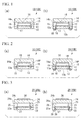
- Example 1 of the first embodiment is shown in (a) of FIG. 2 , and is provided with a projecting portion 14P on the cap substrate 14.
- the spacer 15 consisting of resin
- the moisture permeability coefficient of resin is high, when the closure thickness of the resin is thick, there is a possibility of condensation forming in the gap 13.
- the distance from the semiconductor substrate 12 to the cap substrate 14 is short, optical problems related to such as imaging characteristics will arise.
- the cap substrate 14 By equipping the cap substrate 14 with the projecting portion 14P in order to deal with both of these, thinning of the resin layer with a high moisture permeability coefficient is achieved and the condensation is suppressed, and by controlling the projecting portion 14P on the cap substrate 14, it is possible to adjust the distance from the semiconductor substrate 12 to the cap substrate 14.
- the height of the spacer 15 that joins the semiconductor substrate 12 and the projecting portion 14P on the cap substrate 14 is preferably 0.5 to 3 ⁇ m.
- the distance from the semiconductor substrate 12 to the cap substrate 14 is preferably 10 to 100 ⁇ m.
- Example 2 of the second embodiment of the present invention as shown in (a) of FIG. 4 , a projecting portion 24P is provided on the cap substrate 24. With this constitution, the same effect as Example 1 is obtained.
- Example 3 of the third embodiment of the present invention as shown in (a) of FIG. 6 , a projecting portion 34P is provided on the cap substrate 34. With this constitution, it is possible to obtain the same effect as Example 1 and Example 2.
- the semiconductor package of the present invention as shown in (b) of FIG. 1 , it is possible to provide a penetration electrode 18 and a solder bump 19.
- the penetration electrode 18 is provided from the other surface 12b side of the semiconductor substrate 12 toward the electrode 17, and the solder bump 19 is provided in electrical connection with this penetration electrode 18.
- the penetration electrodes 28, 38 and the solder bumps 29, 39 similarly in the second embodiment and the third embodiment.
- an electrically conducting path is formed that enables the electrode 17 to conduct with the outside via the though electrode 18.
- the shape of the penetration electrode 18 is not particularly limited, but it is preferable to install it at a right angle to the semiconductor device 11. Also, as the material thereof, it is preferable to use metal, such as tin or copper. It is possible to form a back wiring layer on the other surface 12b of the semiconductor substrate 12 so as to make contact with this penetration electrode 18.
- solder bump 19 it is formed on the other surface 12b of the semiconductor substrate where the penetration electrode 18 is disposed, and installed so as to be in electrical contact with the penetration electrode 18.
- the solder alloy that is used is not particularly limited, but in the case of using a lead-free solder alloy, it is preferable to use Sn Ag 3.0 Cu 0.5 or Sn Ag 3.5 Cu 0.7, and more preferable to use Sn Ag 3.0 Cu 0.5.
- the size of the solder bump 19 and the pitch of forming the solder bump 19 are not particularly limited, but it is preferable for the size to be 30 to 250 ⁇ m and the pitch to be 100 to 400 ⁇ m.
- the semiconductor package that is provided with the penetration electrode and the solder bump in the first embodiment of the present invention, as the Example 4, it is possible to use one that is similarly provided with a projecting portion 14P on the cap substrate.
- the spacer 15 being formed from resin, since the moisture permeability coefficient of resin is high, when the closure thickness of the resin is thick, there is a possibility of condensation forming in the gap 13. Also, if the distance from the semiconductor substrate 12 to the cap substrate 14 is short, optical problems related to such as imaging characteristics will arise.
- the cap substrate 14 By providing the cap substrate 14 with the projecting portion 14P in order to deal with both of these, the resin layer with a high moisture permeability coefficient is thinned and the condensation is suppressed, and by controlling the projecting portion 14P on the cap substrate 14, it is possible to adjust the distance from the semiconductor substrate 12 to the cap substrate 14.
- the height of the spacer 15 that joins the semiconductor substrate 12 and the projecting portion 14P on the cap substrate 14 is preferably 0.5 to 3 ⁇ m.
- the distance from the semiconductor substrate 12 to the cap substrate 14 is preferably 10 to 100 ⁇ m.
- Example 5 in which the projecting portion 24P is installed on the cap substrate 24 as shown in (b) of FIG. 4 . With this constitution, the same effect as Example 4 is obtained.
- Example 6 in which the projecting portion 34P is installed on the cap substrate 34 as shown in (b) of FIG. 6 . With this constitution, the same effect as Example 4 and Example 5 is obtained.
- the filter 16 is formed on the surface 14a of the cap substrate 14 as shown in (a) of FIG. 7 .
- the cap substrate 14 in (a) of FIG. 7 is an aggregate 14' of the cap substrate 14 of the semiconductor package 10A).
- a pattern in accordance with the use condition is formed by technique of photolithography.
- the material of the photosensitive resin it is preferable to use a photopolymerization-type acrylic resin or one based on photo-crosslinkable polyvinyl alcohol.
- a color filter when forming a color filter, it is possible to form it by an etching method with a polyimide precursor that is dispersed with a pigment serving as a colored resin layer. Also, there are some that consist of laminating TiO 2 , SiO 2 , MgF 2 , Ta 2 O 5 and the like by vapor deposition.
- the spacer 15 is formed so as to be installed in a projecting manner on the cap substrate 14a, and the semiconductor substrate 12' on which the semiconductor device 11 and the electrode 17 are disposed is bonded.
- the semiconductor substrate 12 in (b) of FIG. 7 is an aggregate 12' of the semiconductor substrate 12 of the semiconductor package 10A).
- the cap substrate 14 is made to face the semiconductor substrate 12', and the spacer 15 that is formed on the surface 14a of the cap substrate 14 is bonded to the surface 12a of the semiconductor substrate 12. Thereby, the semiconductor substrate 12 and the cap substrate 14 are joined via the spacer 15. It is preferable to join them using an epoxy resin or a photosensitive BCB resin or the like.
- the semiconductor package 10A of the present embodiment is obtained as shown in (c) of FIG. 7 .
- the filter 16 is formed on a portion of the surface 14a of the cap substrate 14 without being formed on the entire surface thereof, it is possible to relieve warping of the cap substrate 14 by the stress of the filter 16. Also, the filter 16 is not installed on the dicing location L; it is possible to prevent exfoliation of the filter 16 by chipping due to dicing. Furthermore, since the filter 16 is not caught by the spacer 15 and the cap substrate 14, it is possible to also prevent the filter 16 from exfoliating by the stress arising from the expansion and contraction of the spacer 15. Also, since the filter 16 is formed inside of the semiconductor package 10A, the filter 16 is protected during the processing of the semiconductor package 10A.
- FIG. 8 is a cross-sectional process drawing that describes the method of manufacturing the semiconductor package 20A according to the second embodiment of the present invention.
- the filter 26 is formed on the other surface 24b of the cap substrate 24, as shown in (a) of FIG. 8 .
- the cap substrate 24 in (a) of FIG. 8 is an aggregate 24' of the cap substrate 24 of the semiconductor package 20A).
- the method of forming the filter 26 is the same as that of the first embodiment.
- a protective film 50 is formed so as to cover the filter 26.
- this protective film 50 it is preferably one that can be removed in a subsequent step, and is preferably one that uses a resin that can be removed or a fine adhesion film.
- a laminate of film, a spin coat of resin that can be removed, or the like, is used.
- the cap substrate 24, the spacer 25, and the semiconductor substrate 22 are joined as shown in (c) of FIG. 8 .
- the semiconductor substrate 22 in (c) of FIG. 8 is an aggregate 22' of the semiconductor substrate 22 of the semiconductor package 20A).
- the protective film 50 that was formed in (b) of FIG. 8 is removed.
- a chemical or in the case of film a separator
- the semiconductor package 20A of the present embodiment is obtained as shown in (e) of FIG. 8 .
- the manufacturing method of the semiconductor package 20A of the second embodiment of the present invention it is possible to prevent exfoliation of the filter 26 by the same reason as the first embodiment. Also, since the filter 26 that is formed on the other surface 24b of the cap substrate 24 is covered by the protective film 50 after formation of the filter 26, it is possible to prevent damage to the filter 26 during the manufacturing process.
- FIG. 9 is a cross-sectional process drawing that describes the method of manufacturing the semiconductor package 30A according to the third embodiment.
- explanations that overlap with the first embodiment and the second embodiment shall be omitted.
- first the first filter 36a and the second filter 36b are formed on the surface 34a of the cap substrate 34 and the other surface 34b of the cap substrate 34, respectively, as shown in (a) of FIG. 9 .
- the cap substrate 34 in (a) of FIG. 9 is an aggregate 34' of the cap substrate 34 of the semiconductor package 30A).
- the method of forming the first filter 36a and the second filter 36b is the same as that of the first embodiment and the second embodiment.
- the second filter 36b is covered with a protective film 50.
- a protective film 50 In relation to the method of forming the protective film 50, it is the same as the case of the second embodiment.
- the cap substrate 34, the spacer 35, and the semiconductor substrate 32 are joined as shown in (c) of FIG. 9 .
- the semiconductor substrate 32 in (c) of FIG. 9 is an aggregate 32' of the semiconductor substrate 32 of the semiconductor package 30A).
- the semiconductor package 30A of the present embodiment is obtained as shown in (e) of FIG. 9 .
- the third embodiment it is possible to prevent exfoliation of the first filter 36a and the second filter 36b for the same reason as the first embodiment and the second embodiment. Also, in relation to the first filter 36a, since the filter is formed in the semiconductor package 30, and also in relation to the second filter 36b since it is provided with a step of covering with a protective film similarly to the second embodiment, it is possible to prevent damage to both filters during the manufacturing process.
- the filter 16 is formed on the surface 14a of the cap substrate 14 as shown in (a) of FIG. 10 .
- the cap substrate 14 in (a) of FIG. 10 is an aggregate 14' of the cap substrate 14 of the semiconductor package 10B).
- a pattern in accordance with the use condition is formed by technique of photolithography.
- the material of the photosensitive resin it is preferable to use a photopolymerization-type acrylic resin or one based on photo-crosslinkable polyvinyl alcohol. Also, when forming a color filter, it is possible to form it by an etching method with a polyimide precursor that is dispersed with a pigment serving as a colored resin layer.
- the spacer 15 is formed so as to be installed in a projecting manner on the cap substrate 14a, and the semiconductor substrate 12 on which the semiconductor device 11 and the electrode 17 are disposed is bonded.
- the semiconductor substrate 12 in (b) of FIG. 10 is an aggregate 12' of the semiconductor substrate 12 of the semiconductor package 10B).
- the cap substrate 14 is made to face the semiconductor substrate 12, and the spacer 15 that is formed on the surface 14a of the cap substrate 14 is bonded to the surface 12a of the semiconductor substrate 12. Thereby, the semiconductor substrate 12 and the cap substrate 14 are joined via the spacer 15. It is preferable to join them using an epoxy resin or a photosensitive BCB resin or the like.
- through holes are formed from the other surface 12b of the semiconductor substrate 12 toward the electrode 17.
- a silicon deep etching apparatus (DeepRIE).
- An SiO 2 layer is formed in each through hole as an oxide film layer using plasma-enhanced chemical vapor deposition to form an insulative layer in each through hole.
- the SiO 2 layer of the hole bottom portion is selectively removed.
- a seed layer is formed by sputtering, and the penetration electrode 18 and, although not shown in the drawing, where necessary a back wiring layer are formed by electrolytic plating.
- the solder bumps 19 are formed so as to be electrically connected to the penetration electrodes 18.
- the solder bumps 19 are manufactured so as to be electrically connected to the back wiring layer.
- the semiconductor package 10B that is provided with the penetration electrodes 18 and the solder bumps 19 is obtained as shown in (e) of FIG. 10 .
- the filter 16 since the filter 16 is not installed on the dicing location L, it is possible to prevent exfoliation of the filter 16 by chipping due to dicing. Furthermore, since the filter 16 is formed on a portion of the surface 14a of the cap substrate 14 without being formed on the entire surface thereof, it is possible to relieve warping of the cap substrate 14 by the stress of the filter 16. Furthermore, since the filter 16 is not caught by the spacer 15 and the cap substrate 14, it is possible to also prevent the filter 16 from exfoliating by the stress arising from the expansion and contraction of the spacer 15. In addition, since the filter 16 is formed inside of the semiconductor package 10B, the filter 16 is protected during the processing of the semiconductor package 10B. In relation to the penetration electrode 18, since the opening location is not disposed on the dicing location, it is possible to prevent entry of particles or the like and deformation and the like due to dicing.
- FIG. 11 is a cross-sectional process drawing that describes the method of manufacturing the semiconductor package 20B that is provided with the penetration electrode 28 and the solder bump 29 in the second embodiment of the present invention.
- the filter 26 is formed on the other surface 24b of the cap substrate 24 as shown in (a) of FIG. 11 .
- the method of forming the filter 26 is the same as (a) of FIG. 10 .
- the cap substrate 24 in (a) of FIG. 11 is an aggregate 24' of the cap substrate 24 of the semiconductor package 20B).
- a protective film 50 is formed so as to cover the filter 26.
- this protective film 50 it is preferably one that can be removed in a subsequent step, and is preferably one that uses a resin that can be removed or a fine adhesion film.
- a spin coat of resin that can be removed, or a laminate of dry film (fine adhesion film or the like) is used.
- the cap substrate 24, the spacer 25, and the semiconductor substrate 22 are joined as shown in (c) of FIG. 11 .
- the semiconductor substrate 22 in (c) of FIG. 11 is an aggregate 22' of the semiconductor substrate 22 of the semiconductor package 20B).
- the penetration electrode 28 is formed from the other surface 22b of the semiconductor substrate 22 toward the electrode 27. In relation to the formation of the penetration electrode 28, it is the same as (c) of FIG. 10 .
- solder bump 29 is formed similarly to (d) of FIG. 10 so as to be electrically connected to the penetration electrode 28.
- the protective film 50 that was formed in (b) of FIG. 11 is removed.
- a chemical or dry process is used so as not to impart damage to the filter 26.
- O 2 ashing it is preferable to use O 2 ashing.
- the semiconductor package 20B of the present embodiment is obtained as shown in (g) of FIG. 11
- the manufacturing method of the present embodiment it is possible to prevent exfoliation of the filter 26 by the same reason as the first embodiment of FIG. 10 provided with the penetration electrodes 28 and the solder bumps 29. Also, since the filter 26 that is formed on the other surface 24b of the cap substrate 24 is covered by the protective film 50 after formation of the filter 26, it is possible to prevent damage to the filter 26 during the manufacturing process. Also, in relation to the penetration electrodes 28, since the opening location is not disposed at the dicing location, it is possible to prevent entry of particles or the like and deformation or the like due to dicing.
- FIG. 12 is a cross-sectional process drawing that describes the method of manufacturing the semiconductor package 30B according to the third embodiment that is provided with the penetration electrodes and the solder bumps.
- first the first filter 36a and the second filter 36b are formed on the surface 34a of the cap substrate 34 and the other surface 34b of the cap substrate 34, respectively, as shown in (a) of FIG. 12 .
- the cap substrate 34 in (a) of FIG. 12 is an aggregate 34' of the cap substrate 34 of the semiconductor package 30B).
- the method of forming the first filter 36a and the second filter 36b is the same as the manufacturing process of FIG. 10 .
- the second filter 36b is covered with a protective film 50.
- a protective film 50 In relation to the method of forming the protective film 50, it is the same as the manufacturing process of (b) of FIG. 11 .
- the cap substrate 34, the spacer 35, and the semiconductor substrate 32 are joined as shown in (c) of FIG. 12 .
- the semiconductor substrate 32 in (c) of FIG. 12 is an aggregate 32' of the semiconductor substrate 32 of the semiconductor package 30B).
- the penetration electrode 38 is formed from the other surface 32b of the semiconductor substrate 32 toward the electrode 37. In relation to the formation of the penetration electrode 38, it is the same as (c) of FIG. 10 .
- solder bump 39 is formed similarly to (d) of FIG. 10 so as to be electrically connected to the penetration electrode 38.
- the semiconductor package 30B of the present embodiment is obtained as shown in (g) of FIG. 12 .
- the present embodiment it is possible to prevent exfoliation of the first filter 36a and the second filter 36b by the same reason as the manufacturing steps of FIG. 11 and FIG. 12 . Also, in relation to the first filter 36a, since the filter is formed in the semiconductor package 30B, and also in relation to the second filter 36b since it is provided with a step of covering with the protective film 50 similarly to the second embodiment, it is possible to prevent damage to both filters during the manufacturing process. Also, in relation to the penetration electrode 38, since the opening location is not disposed on the dicing location, it is possible to prevent entry of particles or the like and deformation or the like due to dicing.
- one that is provided with the projecting portion 14P on the cap substrate 14 as shown in Examples 1 and 4 may be used.
- the spacer 15 being formed from resin, since the moisture permeability coefficient of resin is high, when the closure thickness of the resin is thick, there is a possibility of condensation forming in the gap 13. Also, if the distance from the semiconductor substrate 12 to the cap substrate 14 is short, optical problems related to such as imaging characteristics will arise.
- the cap substrate 14 By providing the cap substrate 14 with the projecting portion 14P in order to deal with both of these, thinning of the resin layer with a high moisture permeability coefficient is achieved and the condensation is suppressed, and by controlling the projecting portion 14P on the cap substrate 14, it is possible to adjust the distance from the semiconductor substrate 12 to the cap substrate 14.
- the height of the spacer 15 that joins the semiconductor substrate 12 and the projecting portion 14P on the cap substrate 14 is preferably 0.5 to 3 ⁇ m.
- the distance from the semiconductor substrate 12 to the cap substrate 14 is preferably 10 to 100 ⁇ m.
- the present invention is particularly useful in the case of disposing a filter on a cap substrate in packaging on a wafer level of a semiconductor device that is formed on a semiconductor substrate.
Landscapes
- Engineering & Computer Science (AREA)
- Power Engineering (AREA)
- Microelectronics & Electronic Packaging (AREA)
- Computer Hardware Design (AREA)
- Physics & Mathematics (AREA)
- Condensed Matter Physics & Semiconductors (AREA)
- General Physics & Mathematics (AREA)
- Electromagnetism (AREA)
- Manufacturing & Machinery (AREA)
- Solid State Image Pick-Up Elements (AREA)
Applications Claiming Priority (2)
| Application Number | Priority Date | Filing Date | Title |
|---|---|---|---|
| JP2007171915A JP2009010261A (ja) | 2007-06-29 | 2007-06-29 | 半導体パッケージおよびその製造方法 |
| PCT/JP2008/061773 WO2009005017A1 (fr) | 2007-06-29 | 2008-06-27 | Boîtier semi-conducteur et procédé de fabrication correspondant |
Publications (2)
| Publication Number | Publication Date |
|---|---|
| EP2164098A1 true EP2164098A1 (fr) | 2010-03-17 |
| EP2164098A4 EP2164098A4 (fr) | 2013-03-13 |
Family
ID=40226063
Family Applications (1)
| Application Number | Title | Priority Date | Filing Date |
|---|---|---|---|
| EP08790715A Withdrawn EP2164098A4 (fr) | 2007-06-29 | 2008-06-27 | Boîtier semi-conducteur et procédé de fabrication correspondant |
Country Status (7)
| Country | Link |
|---|---|
| US (1) | US8330268B2 (fr) |
| EP (1) | EP2164098A4 (fr) |
| JP (1) | JP2009010261A (fr) |
| KR (1) | KR20100025538A (fr) |
| CN (1) | CN101689533A (fr) |
| TW (1) | TW200913239A (fr) |
| WO (1) | WO2009005017A1 (fr) |
Cited By (4)
| Publication number | Priority date | Publication date | Assignee | Title |
|---|---|---|---|---|
| EP2287910A1 (fr) * | 2009-08-17 | 2011-02-23 | STMicroelectronics (Research & Development) Limited | Améliorations de ou associées à des filtres dans un capteur d'images |
| WO2011035783A1 (fr) * | 2009-09-24 | 2011-03-31 | Msg Lithoglas Ag | Procédé de réalisation d'un agencement comprenant un composant appliqué sur un substrat support et agencement ainsi que procédé de réalisation d'un produit semi-fini et produit semi-fini |
| WO2011156926A1 (fr) * | 2010-06-14 | 2011-12-22 | Heptagon Oy | Procédé de fabrication d'une pluralité de dispositifs optiques |
| US9820637B2 (en) | 2012-09-24 | 2017-11-21 | Olympus Corporation | Image pickup apparatus and endoscope including image pickup apparatus |
Families Citing this family (12)
| Publication number | Priority date | Publication date | Assignee | Title |
|---|---|---|---|---|
| JPWO2010095201A1 (ja) * | 2009-02-20 | 2012-08-16 | パナソニック株式会社 | 半導体装置及び半導体装置の製造方法 |
| US9075182B2 (en) * | 2011-06-03 | 2015-07-07 | VisEra Technology Company Limited | Camera module and spacer of a lens structure in the camera module |
| KR101980634B1 (ko) * | 2011-06-30 | 2019-05-22 | 엘지이노텍 주식회사 | 렌즈 유닛, 및 이를 포함하는 카메라 모듈 |
| KR101980657B1 (ko) * | 2011-06-30 | 2019-05-22 | 엘지이노텍 주식회사 | 렌즈 어셈블리의 제조방법 |
| JP5903796B2 (ja) * | 2011-08-12 | 2016-04-13 | ソニー株式会社 | 撮像装置およびカメラモジュール |
| TWI462266B (zh) * | 2012-03-20 | 2014-11-21 | Chipmos Technologies Inc | 晶片堆疊結構及其製造方法 |
| US9427776B2 (en) * | 2012-08-23 | 2016-08-30 | Raytheon Company | Method of stress relief in anti-reflective coated cap wafers for wafer level packaged infrared focal plane arrays |
| JP6185813B2 (ja) * | 2013-09-30 | 2017-08-23 | 三星ダイヤモンド工業株式会社 | イメージセンサ用ウエハ積層体の分断方法並びに分断装置 |
| US10720534B2 (en) * | 2014-12-24 | 2020-07-21 | Fujikura Ltd. | Pressure sensor and pressure sensor module |
| JP6054501B1 (ja) * | 2015-12-17 | 2016-12-27 | 株式会社フジクラ | 終端装置および終端方法 |
| US11174705B2 (en) | 2019-04-30 | 2021-11-16 | Weatherford Technology Holdings, Llc | Tubing tester valve and associated methods |
| JP7462620B2 (ja) * | 2019-05-15 | 2024-04-05 | ソニーセミコンダクタソリューションズ株式会社 | 半導体パッケージ、半導体パッケージの製造方法、および、電子装置 |
Citations (5)
| Publication number | Priority date | Publication date | Assignee | Title |
|---|---|---|---|---|
| US20050068456A1 (en) * | 2003-09-25 | 2005-03-31 | Konica Minolta Opto, Inc. | Image pickup device and portable terminal |
| US20060043262A1 (en) * | 2004-08-30 | 2006-03-02 | Micron Technology, Inc. | Microelectronic imagers with integrated optical devices and methods for manufacturing such microelectronic imagers |
| US20060226452A1 (en) * | 2005-04-08 | 2006-10-12 | Konica Minolta Opto, Inc. | Solid-state image pickup device and the manufacture method thereof |
| JP2007129164A (ja) * | 2005-11-07 | 2007-05-24 | Sharp Corp | 光学装置用モジュール、光学装置用モジュールの製造方法、及び、構造体 |
| US20070126898A1 (en) * | 2004-09-27 | 2007-06-07 | Digital Optics Corporation | Thin camera and associated methods |
Family Cites Families (10)
| Publication number | Priority date | Publication date | Assignee | Title |
|---|---|---|---|---|
| JP2002373977A (ja) * | 2001-06-14 | 2002-12-26 | Canon Inc | 固体撮像装置 |
| US7276798B2 (en) * | 2002-05-23 | 2007-10-02 | Honeywell International Inc. | Integral topside vacuum package |
| JP2005125447A (ja) * | 2003-10-23 | 2005-05-19 | Hitachi Ltd | 電子部品およびその製造方法 |
| US7303645B2 (en) * | 2003-10-24 | 2007-12-04 | Miradia Inc. | Method and system for hermetically sealing packages for optics |
| JP2005136144A (ja) * | 2003-10-30 | 2005-05-26 | Kyocera Corp | 固体撮像装置 |
| JP4761713B2 (ja) * | 2004-01-28 | 2011-08-31 | 京セラ株式会社 | 電子部品封止用基板および多数個取り用電子部品封止用基板ならびに電子装置の製造方法 |
| JP4381274B2 (ja) | 2004-10-04 | 2009-12-09 | シャープ株式会社 | 半導体装置およびその製造方法 |
| JP2006173557A (ja) * | 2004-11-22 | 2006-06-29 | Toshiba Corp | 中空型半導体装置とその製造方法 |
| JP4889974B2 (ja) * | 2005-08-01 | 2012-03-07 | 新光電気工業株式会社 | 電子部品実装構造体及びその製造方法 |
| JP2007171915A (ja) | 2005-11-22 | 2007-07-05 | Ricoh Co Ltd | 画像形成装置及び画像形成方法 |
-
2007
- 2007-06-29 JP JP2007171915A patent/JP2009010261A/ja active Pending
-
2008
- 2008-06-27 KR KR1020097027099A patent/KR20100025538A/ko not_active Application Discontinuation
- 2008-06-27 EP EP08790715A patent/EP2164098A4/fr not_active Withdrawn
- 2008-06-27 CN CN200880022659A patent/CN101689533A/zh active Pending
- 2008-06-27 WO PCT/JP2008/061773 patent/WO2009005017A1/fr active Application Filing
- 2008-06-30 TW TW097124527A patent/TW200913239A/zh unknown
-
2009
- 2009-12-28 US US12/648,172 patent/US8330268B2/en not_active Expired - Fee Related
Patent Citations (5)
| Publication number | Priority date | Publication date | Assignee | Title |
|---|---|---|---|---|
| US20050068456A1 (en) * | 2003-09-25 | 2005-03-31 | Konica Minolta Opto, Inc. | Image pickup device and portable terminal |
| US20060043262A1 (en) * | 2004-08-30 | 2006-03-02 | Micron Technology, Inc. | Microelectronic imagers with integrated optical devices and methods for manufacturing such microelectronic imagers |
| US20070126898A1 (en) * | 2004-09-27 | 2007-06-07 | Digital Optics Corporation | Thin camera and associated methods |
| US20060226452A1 (en) * | 2005-04-08 | 2006-10-12 | Konica Minolta Opto, Inc. | Solid-state image pickup device and the manufacture method thereof |
| JP2007129164A (ja) * | 2005-11-07 | 2007-05-24 | Sharp Corp | 光学装置用モジュール、光学装置用モジュールの製造方法、及び、構造体 |
Non-Patent Citations (1)
| Title |
|---|
| See also references of WO2009005017A1 * |
Cited By (5)
| Publication number | Priority date | Publication date | Assignee | Title |
|---|---|---|---|---|
| EP2287910A1 (fr) * | 2009-08-17 | 2011-02-23 | STMicroelectronics (Research & Development) Limited | Améliorations de ou associées à des filtres dans un capteur d'images |
| WO2011035783A1 (fr) * | 2009-09-24 | 2011-03-31 | Msg Lithoglas Ag | Procédé de réalisation d'un agencement comprenant un composant appliqué sur un substrat support et agencement ainsi que procédé de réalisation d'un produit semi-fini et produit semi-fini |
| EP3297036A1 (fr) * | 2009-09-24 | 2018-03-21 | MSG Lithoglas GmbH | Procédé de fabrication d'un dispositif pourvu d'un élément de construction sur un substrat de support et dispositif ainsi que procédé de fabrication d'un produit semi-fini |
| WO2011156926A1 (fr) * | 2010-06-14 | 2011-12-22 | Heptagon Oy | Procédé de fabrication d'une pluralité de dispositifs optiques |
| US9820637B2 (en) | 2012-09-24 | 2017-11-21 | Olympus Corporation | Image pickup apparatus and endoscope including image pickup apparatus |
Also Published As
| Publication number | Publication date |
|---|---|
| KR20100025538A (ko) | 2010-03-09 |
| WO2009005017A1 (fr) | 2009-01-08 |
| JP2009010261A (ja) | 2009-01-15 |
| EP2164098A4 (fr) | 2013-03-13 |
| US8330268B2 (en) | 2012-12-11 |
| CN101689533A (zh) | 2010-03-31 |
| US20100102437A1 (en) | 2010-04-29 |
| TW200913239A (en) | 2009-03-16 |
Similar Documents
| Publication | Publication Date | Title |
|---|---|---|
| EP2164098A1 (fr) | Boîtier semi-conducteur et procédé de fabrication correspondant | |
| US8102039B2 (en) | Semiconductor device and manufacturing method thereof | |
| JP5344336B2 (ja) | 半導体装置 | |
| US9034729B2 (en) | Semiconductor device and method of manufacturing the same | |
| EP2587793B1 (fr) | Dispositif de capture d'image et module de dispositif de capture d'image | |
| JP4693827B2 (ja) | 半導体装置とその製造方法 | |
| KR100917745B1 (ko) | 반도체 장치 및 그 제조 방법 | |
| US10200010B2 (en) | Elastic wave filter device | |
| KR20110054710A (ko) | 소자 패키지 및 그 제조 방법 | |
| KR20010092663A (ko) | 고체 촬상장치 및 그 제조방법 | |
| JP2006210756A (ja) | 電子装置及びその製造方法 | |
| US9966400B2 (en) | Photosensitive module and method for forming the same | |
| CN110993513A (zh) | 一种cis芯片的晶圆级扇出型封装方法以及结构 | |
| JP2009267122A (ja) | 半導体装置 | |
| JP3614840B2 (ja) | 半導体装置 | |
| JP4468427B2 (ja) | 半導体装置の製造方法 | |
| US20050275075A1 (en) | Micro-electro-mechanical system (MEMS) package with spacer for sealing and method of manufacturing the same | |
| US20100065956A1 (en) | Packaging structure, packaging method and photosensitive device | |
| JP4314825B2 (ja) | 光モジュール及びその製造方法、回路基板並びに電子機器 | |
| US9478677B2 (en) | Electronic device comprising an optical sensor chip | |
| CN114639741A (zh) | 影像传感芯片的封装结构及封装方法 | |
| US20180301488A1 (en) | Image sensing chip packaging structure and packaging method | |
| JP4939313B2 (ja) | 半導体装置の製造方法 | |
| US20180226442A1 (en) | Image sensor and manufacturing method thereof | |
| JP5408995B2 (ja) | 半導体パッケージ |
Legal Events
| Date | Code | Title | Description |
|---|---|---|---|
| PUAI | Public reference made under article 153(3) epc to a published international application that has entered the european phase |
Free format text: ORIGINAL CODE: 0009012 |
|
| 17P | Request for examination filed |
Effective date: 20100105 |
|
| AK | Designated contracting states |
Kind code of ref document: A1 Designated state(s): AT BE BG CH CY CZ DE DK EE ES FI FR GB GR HR HU IE IS IT LI LT LU LV MC MT NL NO PL PT RO SE SI SK TR |
|
| AX | Request for extension of the european patent |
Extension state: AL BA MK RS |
|
| DAX | Request for extension of the european patent (deleted) | ||
| A4 | Supplementary search report drawn up and despatched |
Effective date: 20130213 |
|
| RIC1 | Information provided on ipc code assigned before grant |
Ipc: H01L 23/12 20060101ALI20130207BHEP Ipc: H04N 5/335 20110101ALI20130207BHEP Ipc: H01L 27/146 20060101ALN20130207BHEP Ipc: H01L 31/0232 20060101ALN20130207BHEP Ipc: H01L 23/02 20060101AFI20130207BHEP Ipc: H01L 27/14 20060101ALI20130207BHEP Ipc: H01L 31/0203 20060101ALN20130207BHEP |
|
| STAA | Information on the status of an ep patent application or granted ep patent |
Free format text: STATUS: THE APPLICATION IS DEEMED TO BE WITHDRAWN |
|
| 18D | Application deemed to be withdrawn |
Effective date: 20130917 |