EP2127159B1 - System und portables gerät für die übertragung von identifikationssignalen - Google Patents
System und portables gerät für die übertragung von identifikationssignalen Download PDFInfo
- Publication number
- EP2127159B1 EP2127159B1 EP08706359.0A EP08706359A EP2127159B1 EP 2127159 B1 EP2127159 B1 EP 2127159B1 EP 08706359 A EP08706359 A EP 08706359A EP 2127159 B1 EP2127159 B1 EP 2127159B1
- Authority
- EP
- European Patent Office
- Prior art keywords
- transmitter electronics
- electrodes
- data
- portable apparatus
- transmitter
- Prior art date
- Legal status (The legal status is an assumption and is not a legal conclusion. Google has not performed a legal analysis and makes no representation as to the accuracy of the status listed.)
- Not-in-force
Links
- 238000004891 communication Methods 0.000 claims description 25
- 230000005540 biological transmission Effects 0.000 claims description 23
- 230000008054 signal transmission Effects 0.000 claims description 5
- 230000001419 dependent effect Effects 0.000 claims description 2
- 230000008878 coupling Effects 0.000 description 8
- 238000010168 coupling process Methods 0.000 description 8
- 238000005859 coupling reaction Methods 0.000 description 8
- 238000000034 method Methods 0.000 description 7
- 230000000694 effects Effects 0.000 description 6
- 238000011084 recovery Methods 0.000 description 6
- 238000013459 approach Methods 0.000 description 5
- 206010011906 Death Diseases 0.000 description 4
- 238000005516 engineering process Methods 0.000 description 4
- 230000033001 locomotion Effects 0.000 description 4
- 230000004913 activation Effects 0.000 description 3
- 230000006870 function Effects 0.000 description 3
- 238000007726 management method Methods 0.000 description 3
- 230000004044 response Effects 0.000 description 3
- 101100389788 Arabidopsis thaliana EOL2 gene Proteins 0.000 description 2
- 241000202252 Cerberus Species 0.000 description 2
- 101150000637 EOL1 gene Proteins 0.000 description 2
- 238000001514 detection method Methods 0.000 description 2
- 238000003825 pressing Methods 0.000 description 2
- 238000005096 rolling process Methods 0.000 description 2
- 230000001360 synchronised effect Effects 0.000 description 2
- HBBGRARXTFLTSG-UHFFFAOYSA-N Lithium ion Chemical compound [Li+] HBBGRARXTFLTSG-UHFFFAOYSA-N 0.000 description 1
- 230000003213 activating effect Effects 0.000 description 1
- 230000006399 behavior Effects 0.000 description 1
- 230000008901 benefit Effects 0.000 description 1
- 239000000969 carrier Substances 0.000 description 1
- 239000000919 ceramic Substances 0.000 description 1
- 230000008859 change Effects 0.000 description 1
- 239000004020 conductor Substances 0.000 description 1
- 238000012937 correction Methods 0.000 description 1
- 238000013461 design Methods 0.000 description 1
- 230000005684 electric field Effects 0.000 description 1
- 238000005265 energy consumption Methods 0.000 description 1
- 230000002349 favourable effect Effects 0.000 description 1
- 238000002372 labelling Methods 0.000 description 1
- 229910001416 lithium ion Inorganic materials 0.000 description 1
- 238000004519 manufacturing process Methods 0.000 description 1
- 239000000463 material Substances 0.000 description 1
- 238000012544 monitoring process Methods 0.000 description 1
- 238000012545 processing Methods 0.000 description 1
- 238000001228 spectrum Methods 0.000 description 1
- 230000007480 spreading Effects 0.000 description 1
- 238000003892 spreading Methods 0.000 description 1
- 238000003860 storage Methods 0.000 description 1
- 238000012546 transfer Methods 0.000 description 1
- 230000007704 transition Effects 0.000 description 1
- 230000002618 waking effect Effects 0.000 description 1
Images



Classifications
-
- H—ELECTRICITY
- H04—ELECTRIC COMMUNICATION TECHNIQUE
- H04B—TRANSMISSION
- H04B13/00—Transmission systems characterised by the medium used for transmission, not provided for in groups H04B3/00 - H04B11/00
- H04B13/005—Transmission systems in which the medium consists of the human body
-
- G—PHYSICS
- G07—CHECKING-DEVICES
- G07C—TIME OR ATTENDANCE REGISTERS; REGISTERING OR INDICATING THE WORKING OF MACHINES; GENERATING RANDOM NUMBERS; VOTING OR LOTTERY APPARATUS; ARRANGEMENTS, SYSTEMS OR APPARATUS FOR CHECKING NOT PROVIDED FOR ELSEWHERE
- G07C9/00—Individual registration on entry or exit
- G07C9/20—Individual registration on entry or exit involving the use of a pass
-
- G—PHYSICS
- G07—CHECKING-DEVICES
- G07C—TIME OR ATTENDANCE REGISTERS; REGISTERING OR INDICATING THE WORKING OF MACHINES; GENERATING RANDOM NUMBERS; VOTING OR LOTTERY APPARATUS; ARRANGEMENTS, SYSTEMS OR APPARATUS FOR CHECKING NOT PROVIDED FOR ELSEWHERE
- G07C9/00—Individual registration on entry or exit
- G07C9/00174—Electronically operated locks; Circuits therefor; Nonmechanical keys therefor, e.g. passive or active electrical keys or other data carriers without mechanical keys
- G07C2009/00753—Electronically operated locks; Circuits therefor; Nonmechanical keys therefor, e.g. passive or active electrical keys or other data carriers without mechanical keys operated by active electrical keys
- G07C2009/00809—Electronically operated locks; Circuits therefor; Nonmechanical keys therefor, e.g. passive or active electrical keys or other data carriers without mechanical keys operated by active electrical keys with data transmission through the human body
Definitions
- the invention relates to the communication between a transmitter and a receiver via the capacitive coupling (sometimes referred to as capacitive-resistive coupling, "intrabody” coupling or PAN coupling) in which small currents are generated in the human body, which for Information transmission between the transmitter and the receiver are used, and / in which the transmitter and the receiver over very short distances via electric fields interact with each other.
- capacitive coupling sometimes referred to as capacitive-resistive coupling, "intrabody” coupling or PAN coupling
- EP 1 168 678 A1 shows an intrabody data transmission system with a first device which is worn on the body of a user and having two coplanar electrodes, which are arranged for example on the back of a wristwatch. By applying voltages between the electrodes, a second device which the user touches on a single electrode can be communicated.
- the selectivity of data transmission is particularly advantageous in the capacitive coupling through the human body or over short distances.
- the selectivity of data transmission Depending on the constellation, it can be determined with a relatively high degree of certainty that the signal received by the receiver can only have been transmitted by the person who is in close proximity or in physical contact with a receiver electrode provided for this purpose.
- a disadvantage is, inter alia, that due to the poor signal-to-noise ratio (actually: signal-interference ratio) only a limited amount of data can be transmitted.
- a good signal-to-noise ratio is only possible with a large amplitude of the transmission signal.
- a large amplitude ie high voltage
- WO 2007/112609 solutions are shown that can be used to address this problem. Nevertheless, the bandwidth of the signal transmission remains limited.
- a portable device is by a user, for example, on the body wearable, it can as a card-like identification medium, as a "smart card cover", mobile phone, clock, portable computer (eg. The type "handheld” computer, etc.
- a direct, short-range communication (not by the body), for example by holding the portable device in the immediate vicinity of a receiving electrode, ie applications of the invention are not limited to the coupling by the human body but extend to cases in which the user is carrying the portable device in front of a receiver electrode or otherwise allows communication to take place directly and not exclusively via the body between the transmitter and the receiver.
- the said means for applying the electrical signal between the electrodes part of a transmitter electronics wherein the transmitter electronics also comprises means for generating the electrical signal in response to predetermined data, and the transmitter electronics designed as an application-specific integrated circuit (ASIC) is.
- ASIC application-specific integrated circuit
- the transmitter electronics or the ASIC thus has both means for generating the electrical signal as a function of predetermined data and means for applying the electrical signal between the electrodes.
- the means for generating the electrical signal in response to predetermined data are typically digital circuits for encoding the predetermined data to be transmitted and modulating the data thus encoded.
- the means for Application of the electrical signal between the electrodes are power or amplifier circuits that provide the required power to drive the electrodes.
- the design of transmitter electronics with ASIC has proven the design of transmitter electronics with ASIC to be advantageous in terms of reducing power consumption.
- the ASIC for capacitive-resistive coupling with the method described herein unlike a non-specific, available on the market microprocessor must not have high-frequency oscillators, since all signals are low-frequency.
- the query of unused inputs which also contributes to a background power consumption of microprocessors, falls away.
- the inventive approach especially in combination with a low-frequency transmission (center frequency less than 2 MHz) and ultra broadband signal transmission, the background power consumption by a factor of 100 to 1000 can be reduced compared to the prior art.
- the predetermined data to be transmitted are stored or storable in a further preferred embodiment of the invention in the transmitter electronics itself.
- the portable device includes a data memory, for example in a volatile, or preferably non-volatile memory such as an EEPROM contained in the ASIC.
- the transmitter electronics can be used without further components (in addition to battery and electrodes) for sending identification signals.
- the transmitter electronics in horrsel, smart cards, card carriers, etc. of access control systems can be integrated.
- the data to be transferred thus correspond to a code or key. For applications in which the code does not need to be changed, it can also be stored in a non-rewritable memory.
- the transmitter electronics has an interface for communication with a further unit (or application), which are installed in the portable device or communicate through the interface with the portable device. Via a corresponding communication interface, in particular an I 2 C bus, data to be transmitted from the other application to the transmitter electronics can be transmitted.
- the transmitter electronics are designed to modulate, encode and transmit this data or transmission data obtained from this data.
- the portable device preferably serves, inter alia, as an input unit for the transmitter electronics.
- the portable device may be, for example, a card-shaped identification medium, a "smart card cover" -like identification medium or an identification medium in otherwise a shape, for example in the form of a key fob. It may alternatively be a 'smarter' device with different capabilities, such as a mobile phone or other handheld device such as a PDA (personal digital assistant, or a watch, etc. Modern electronic devices often have large area displays - a first of the two Electrode (and / or receiver) electrodes may be disposed in or over the display, which has the advantage of reduced capacitance when the second transparent or non-transparent electrode is positioned near a rear of the device, for example.
- Combinations of the two preferred embodiments are also conceivable, ie the presence of both a non-volatile memory and the presence of an interface for communication with a portable device, for example.
- parameters of the coding are adaptable according to the requirements of the communication security and speed.
- the driver circuit of the transmitter electronics is also parameterized so that it can be adapted to different categories of electrodes.
- the signal bandwidth and the center frequency (carrier frequency) are also potentially parameterizable in order to achieve the optimum in terms of robust data transmission in a noisy environment.
- the transmitter electronics By providing the transmitter electronics as an integrated circuit with the aforementioned functionality and parameterizability, a widely deployable element is created. This can on the one hand “stand-alone" with a battery, the electrodes and a more or less complex - the use of appropriately adapted - are used circuit provided.
- the data to be transmitted are stored in the transmitter electronics themselves (non-volatile).
- the transmitter electronics as part of the portable device with at least one other application, or standing in at least temporary connection with another application, supplied by this portable device via the communication interface with data to be sent and preferably also be controlled otherwise.
- two electrodes of a portable device are arranged such that either components of an application different from the transmitter electronics are arranged between the electrodes or an air gap is present, into which such a component - for example with a "Smart Card "as a carrier of the component - can be inserted.
- the transmitter electronics and electronic components of the application different from the transmitter electronics can be combined with each other in at least one common component - for example, an integrated circuit - be integrated.
- the inventive feature of the "components of an application different from the transmitter electronics" merely states that electronic elements arranged between the electrodes can perform functions which are completely different from the capacitive-resistive information transmission and preferably also from other non-contact information transmission modes, for example they control the display of a mobile phone, or form by storing and / or storing information that is not transmitted with the capacitive-resistive information transmission, etc.
- the portable device with the air gap can have a communication interface, via which data can be exchanged with the application, which can be inserted into the air gap.
- a communication interface via which data can be exchanged with the application, which can be inserted into the air gap.
- Such an interface may, for example, be designed like a conventional smart-cart reader.
- a communication connection may exist between the transmitter electronics and an input unit, in which case the signals transmitted by the transmitter electronics may be dependent on input data.
- the transmitted signals may include a PIN, which the user has previously entered into the input unit.
- the portable device may, for example, be designed as a mobile telephone, wherein the input unit of the input unit of the mobile phone (keyboard, touch screen, voice recognition device, etc.) may correspond.
- the power supply of the transmitter electronics can be solved in a simple way: namely by the transmitter electronics by the very powerful battery of the mobile phone is fed, for example via a 3V DC supply.
- the communication between the transmitter electronics and the other electronic components of the mobile phone can - if they are not integrated with each other - via any known or still to be developed interface, for example. Via an I 2 C data bus.
- a transmitter electronics with which the at least two electrodes of the transmitter are controlled, includes a charge recovery logic and / or an adiabatic switching logic.
- the charge recovery logic can for example be based on "synchronous rectification”.
- Charge recovery logics are known for integrated circuit capacities, for example in slow CMOS or other integrated circuits.
- the following is the power consumption of a portable device for transmitting signals to a second device, wherein the portable device is a user on the body, having at least two electrodes and a transmitter electronics for applying an electrical signal between the electrodes, so that the signal through the electrodes in the body of the user einkoppelbar and the body by at least one electrode of the second device is detectable, still discussed in more detail on the basis of further aspects. It is assumed in each case that the transmitter electronics are controlled by a battery (rechargeable or non-rechargeable).
- the use of an information transmission method which is based on the frequency spreading method in which the signal is transmitted as an ultra-wideband signal is particularly preferred according to the teaching of the international patent application WO 2007/112609 .
- Ultra broadband is defined as the use of a frequency range of at least 20% of the center frequency or carrier frequency.
- a direct sequence spread spectrum method is used in particular.
- the data are preferably first modulated with a method of digital data modulation and then frequency-spread.
- WO 2007/112609 Methods are also described to evaluate a capacitive-resistive signal.
- the portable device 1 is substantially card-shaped and has a first electrode 3 and a second electrode 4. Between the first and the second electrode there are further elements, for example a plastic carrier 5 with integrated and / or applied electronic components and a battery compartment (not shown in the figure).
- the integrated and / or applied electronic components may include, for example, the ASIC for controlling the electrodes, an EEPROM memory, printed conductor structures and / or further elements.
- the carrier may also be ceramic or of another material, it is only important that the two electrodes are electrically insulated from each other.
- At least one of the electrodes may be at least partially transparent, in the illustrated example, the first electrode 3.
- On an upper side of the plastic carrier 5 labels, pictures, etc. may be applied in a conventional manner, which are visible through the transparent electrode.
- FIG. 2 shows a further embodiment.
- the transmitter 1 is designed as a so-called "smart card cover”.
- Smart Card Covers are known. They are designed as, for example, rigid, transparent casing which, for example, can be attached to a garment and into which a smart card (ie a card-shaped medium with storage and communication functionality) can be inserted.
- the transmitter has a compartment for a battery 6 and a control electronics represented schematically by a chip 7 for the at least partially transparent electrodes 3, 4.
- the Smart Card 11 can be inserted into an air gap.
- a possible labeling field 12 of the smart card remains visible through the transparent first electrode 3.
- FIG. 3 shows a variant of the embodiment of FIG. 2 in which the smart card (or other components of an application different from the transmitter electronics) simultaneously serves as an RFID identification medium.
- the RFID antenna which is not completely covered by one of the electrodes here - in the example shown by the transparent electrode 3.
- transparent electrodes for example electrodes made of ITO - the RFID communication also works if, unlike in the figure, both transparent electrodes completely cover the RFID antenna 15, ie if the transparent electrode 3 the whole upper surface covered in the figure.
- FIGS. 4 and 5 relate to a mobile device 31 designed according to the invention portable device.
- the first electrode 3 is integrated in the display and transparent at least in the display area, while the second electrode 4 as in the above examples of transmitter electrodes not is necessarily transparent.
- the second electrode is located on a rear side of the mobile telephone (or, as in the example shown, of its hinged lid or of another part of the mobile telephone) and, if appropriate, can also be formed by a conductive housing part. It is arranged in the largest possible, fixed distance from the first electrode.
- Fig. 5 is shown very schematically how the transmitter electronics 7 may be in communication with the rest of the mobile phone electronics: The mobile phone feeds the transmitter electronics (3V), and there is a communication connection via an I 2 C interface.
- control of the transmitter electrodes is provided with a charge recovery and / or adiabatic switching logic. Also, as described above, the electrodes are as far apart as possible, and the dielectric constant of the medium / media between the electrodes is as small as possible.
- the transmitter electronics 7 is integrated in a portable device 31, or at least temporarily can communicate with this is according to the FIG. 6 the same transmitter electronics 7 configured for a "stand-alone" operation with additional input / output elements.
- the in the FIG. 6 shown I 2 C interface is only temporarily connected to a host system 46 in a "stand-alone" operation, for example, to configure the transmitter electronics 7.
- FIG. 6 Further aspects are described which are related to the lowest possible power consumption and / or the monitoring of the battery charge.
- the components shown in dotted box in the figure are optional and may be present singly or in combination.
- the transmitter electronics 7 according to FIG. 6 is connected to an output unit 41, via which a status display of the battery charge is made possible.
- Such may comprise a light-emitting diode (LED) or a plurality of light-emitting diodes 41.
- an activity detector 44 can be present which switches off the electrode drive when the portable device 31 or a carrier of the transponder chip 7, for example a key or a card, is not moved.
- the transmitter electronics only become active when a wake-up signal, for example an LF (Low Frequency) wake-up signal, is detected.
- a wake-up signal for example an LF (Low Frequency) wake-up signal
- a corresponding detection unit is provided with the reference numeral 45. Configurations with LF detectors for putting a circuit into operation are already known per se.
- an on-switch 42 is still shown. Such a can be used, for example, when in a "low-comfort mode" with almost empty battery, the electronics has been turned off automatically. By operating the switch 42, the electronics are reactivated for a limited time. Also shown is an on-off switch 43, through which the entire portable device can be turned off when it is not needed. In case of connection to a "host system” (e.g., a mobile phone 31) 46, power management may be somewhat less important.
- switching off the electronics does not rule out that individual components are still active, such as the timer.
- switch off is explicitly meant the transition into such a partially active “sleep” mode.
- the emission of the signal via the electrodes is interrupted in such a sleep mode.
- FIG. 7 shows the internal structure of a transmitter electronics 7 and an ASIC in a preferred embodiment of the invention.
- the ASIC has as main elements a communication interface 61 to an I 2 C bus with lines SDA and SCL, a nonvolatile memory 62, an encoder 63, a modulator 64, and output drivers 67.
- it also has clock circuits 65, a control logic 70 for the output drivers 67 and a power saving logic 71 on.
- the output drivers 67 preferably have different output drivers 68, 69 from which a particular driver can be selected according to the characteristics of the electrodes used.
- the modulator 64 includes a chip generator 66, typically a linear feedback shift register (LFSR).
- LFSR linear feedback shift register
- data to be transmitted can be read into the transmitter electronics 7, and control and operating parameters of the transmitter electronics 7 can be set (for example the length and the parameters of the LFSR).
- the data to be transmitted can be stored in the nonvolatile memory 62 so that the transmitter electronics 7 can subsequently be decoupled from the interface and operated autonomously.
- the data to be transmitted can also be written to a payload register 73 and subsequently overwritten by further data from the communication interface 61.
- the data in the payload register 73 as long as a transmission mode of the transmitter electronics 7 is active, coded, modulated and sent.
- the encoder 63 has, in a manner known per se, a unit for adding redundant correction bits, and for example a differential encoder.
- the code thus generated is preferably ultra-broadband modulated by the modulator 64. In a manner known per se, this is done, for example, by means of a pseudo-random chip sequence.
- Each bit of the code to be transmitted is multiplied by time domain with a multi-bit chip or XORed, resulting in the wideband modulated signal.
- an element can still be present, with which the bandwidth can be varied.
- This can be designed, for example, as a frequency divider (eg flip-flop), which, depending on the specification, effects the signal transmission with full bandwidth or with reduced bandwidth, for example with half the bandwidth.
- the transmitter electronics 7 is designed such that the length of the chip sequence can be predetermined or selected, for example by transferring corresponding parameters via the interface 61. This makes it possible to meet the conflicting requirements with regard to communication security and speed accordingly to adjust the application of the 7.
- the center frequency (carrier frequency) of the transmission can be set by changing a setting of the clock multiplier - quasi by scaling all frequencies.
- the robustness of the data transmission can be optimized even in the presence of interference.
- the center frequency can be switched between discrete values or quasi-continuously by means of a switch or a plurality of switches, or if necessary via the interface a specification for the center frequency can be made as a numerical value and into a corresponding one Memory can be stored.
- the switching states of the switches may possibly also be defined via the interface, or they may, in particular if there is no interface, be externally accessible to a user, for example in the form of DIP switches, or they may already be used during production of the portable device.
- a combination of the possibilities of varying the center frequency between at least two values or continuously and the possibility of likewise varying the bandwidth between at least two values or continuously is particularly favorable. As a result, the presence of possible interference signals can be particularly effectively addressed.
- the control logic 70 for the output drivers 67 determines the output drivers 68, 69 to be used, for example in the following way: with a control signal CL, the order of magnitude of the capacitive load of the electrodes 3, 4 can be selected. With a control signal DR_MD is selectable whether the electrodes are driven differentially or single-ended. With a control signal PSO is selectable whether the electrodes are controlled by means of "synchronous rectification" (wherein an external wiring is required by means of one or two inductors). By means of these control signals, the output drivers 67 and their mode of operation can be adapted to the electrodes 3, 4 used, so that their energy requirement remains as small as possible.
- Output signals LED1, LED2 control LEDs to indicate the battery status.
- Output signals EOL_HI, EOL_LO also indicate the battery level and can be queried and processed by, for example, the portable device 31.
- Line 54 shows the activation of the "Low Comfort Mode Area” 54, in which the portable device only transmits (i.e., has to be taken out of the bag) when actively pressed, ie by pressing a button.
- line 58 In which periods the electrodes are active, so send. This is the case in normal operation when an activity sensor registers movement of the portable device or when receiving a wake-up signal (No. 57). When the movement ceases, the electrodes preferably remain active for a period of time t_del_sleep. In "low comfort mode", the electrodes are only active when the corresponding button is pressed (No. 59). The last peak at the far right of row 58 therefore assumes that the user has actively activated according to row 59.
Landscapes
- Physics & Mathematics (AREA)
- General Physics & Mathematics (AREA)
- Engineering & Computer Science (AREA)
- Computer Networks & Wireless Communication (AREA)
- Signal Processing (AREA)
- Telephone Function (AREA)
- Near-Field Transmission Systems (AREA)
- Telephone Set Structure (AREA)
- Transmitters (AREA)
Description
- Die Erfindung betrifft die Kommunikation zwischen einem Sender (Transmitter) und einem Empfänger über die kapazitive Kopplung (manchmal auch als kapazitiv-resisitive Kopplung, "intrabody"-Kopplung oder PAN-Kopplung bezeichnet) bei welcher im menschlichen Körper kleine Ströme erzeugt werden, die zur Informationsübertragung zwischen dem Transmitter und dem Empfänger benutzt werden, und/der bei welchem der Transmitter und der Empfänger über sehr kurze Distanzen via elektrische Felder miteinander wechselwirken.
- Diese Art der Kopplung ist in den
US-Patentschriften 4,591,854 ,5,914,701 und5,796,827 offenbart. Anwendungen davon sind in der internationalen PatentanmeldungPCT/CH 2006/000518 -
EP 1 168 678 A1 zeigt ein intrabody-Datenübertragungssystem mit einem ersten Gerät, welches am Körper eines Benutzers getragen wird und zwei koplanare Elektroden aufweist, die beispielsweise auf der Hinterseite einer Armbanduhr angeordnet sind. Durch Anlegen respektive Messen von Spannungen zwischen den Elektroden kann mit einem zweiten Gerät, welches der Benutzer an einer einzelnen Elektrode berührt, kommuniziert werden. - Besonders vorteilhaft an der kapazitiven Kopplung durch den menschlichen Körper bzw. über kurze Distanzen ist die Selektivität der Datenübertragung. Je nach Konstellation kann man mit recht hoher Sicherheit bestimmen, dass das vom Empfänger empfangene Signal nur durch diejenige Person übertragen worden sein kann, die sich in unmittelbarer Nähe oder in physischem Kontakt zu einer dafür vorgesehenen Empfängerelektrode befindet.
- Nachteilig ist unter anderem, dass aufgrund des schlechten Signal-Rauschverhältnisses (eigentlich: Signal-Interferenzverhältnisses) nur eine beschränkte Datenmenge übertragen werden kann. Ein gutes Signal-Rauschverhältnis ist nur bei einer grossen Amplitude des Übertragungssignals möglich. Eine grosse Amplitude (d.h. hohe Spannung) wird aber vom Benutzer eher nicht toleriert. In der internationalen Patentveröffentlichung
WO 2007/112609 werden Lösungsansätze aufgezeigt, mit denen dieses Problem angegangen werden kann. Trotzdem bleibt die Bandbreite der Signalübertragung beschränkt. - Es bestehen viele Anwendungsmöglichkeiten für die kapazitiv-resisitive Datenübertragung, bekannte Realisierungen sind jedoch auf spezielle Anwendungsfälle zugeschnitten. Für neue Anwendungsfälle muss auch eine neue angepasste Hardware entwickelt werden, welche den spezifischen Anforderungen entsprechend den jeweiligen zu übertragenden Signale und den physischen Umständen angepasst sind. Dieser Zustand ist unbefriedigend.
- Vor diesem Hintergrund ist es Aufgabe der Erfindung, Lösungen für die kapazitiv-resisitive Datenübertragung zur Verfügung zu stellen, die obige Nachteile mindestens zum Teil beheben und die einen weiteren Schritt zur kommerziellen Anwendung der Technologie und deren Akzeptanz durch die Konsumenten bedeuten. Die genannten Lösungen sollten insbesondere bei der Zutrittskontrolle verwertbar sein.
- Diese Aufgabe wird durch die Erfindung gelöst, wie sie in den Patentansprüchen definiert ist.
- Ein portables Gerät gemäss dem erfindungsgemässen Ansatz ist durch einen Benutzer bspw. auf dem Körper tragbar, es kann als kartenartiges Identifikationsmedium, als "Smart Card Cover", Mobiltelefon, Uhr, portabler Computer (bspw. vom Typ "Handheld"-Computer etc. ausgebildet sein. Es weist mindestens zwei Elektroden und Mittel zum Anlegen eines elektrischen Signals zwischen den Elektroden auf, so, dass das Signal durch die Elektroden in den Körper des Benutzers einkoppelbar und vom Körper durch mindestens eine Elektrode des zweiten Geräts detektierbar ist. Ein solches Gerät ermöglicht auch eine direkte, kurzreichweitige Kommunikation (nicht durch den Körper), bspw. durch Halten des portablen Geräts in die unmittelbare Nähe einer Empfängerelektrode, d.h. Anwendungen der Erfindung sind nicht auf die Kopplung durch den menschlichen Körper beschränkt sondern erstrecken sich auch auf Fälle, in denen der Benutzer das portable Gerät vor sich trägt, in die Nähe einer Receiverelektrode hält oder sonstwie ermöglicht, dass die Kommunikation direkt und nicht ausschliesslich über den Körper zwischen Transmitter und Receiver erfolgt.
- Dabei sind gemäss einem Aspekt der Erfindung die genannten Mittel zum Anlegen des elektrischen Signals zwischen den Elektroden Teil einer Transmitterelektronik, wobei die Transmitterelektronik zudem Mittel zum Erzeugen des elektrischen Signals in Abhängigkeit von vorgegebenen Daten aufweist, und die Transmitterelektronik als anwendungsspezifischer Integrierter Schaltkreis (ASIC) ausgeführt ist.
- Die Transmitterelektronik respektive der ASIC weist also sowohl Mittel zum Erzeugen des elektrischen Signals in Abhängigkeit von vorgegebenen Daten als auch Mittel zum Anlegen des elektrischen Signals zwischen den Elektroden auf. Die Mittel zum Erzeugen des elektrischen Signals in Abhängigkeit von vorgegebenen Daten sind typischerweise digitale Schaltkreise zum Codieren der vorgegeben, zu übertragenden Daten und zum Modulieren der so codierten Daten. Die Mittel zum Anlegen des elektrischen Signals zwischen den Elektroden sind Leistungs- oder Verstärkerschaltkreise, welche die erforderliche Leistung zum Treiben der Elektroden aufbringen. Indem sowohl die digitalen Verarbeitungselemente als auch die Treiber auf einem einzigen Integrierten Schaltkreis vorliegen, wird ein flexibler und effizient einsetzbares Bauteil geschaffen.
- Ausserdem hat sie die Ausführung der Transmitterelektronik mit ASIC als vorteilhaft in Bezug auf eine Reduktion des Stromverbrauchs erwiesen. Insbesondere muss der ASIC für die kapazitiv-resistive Kopplung mit dem hier beschriebenen Verfahren im Gegensatz zu einem nicht anwendugnsspezifischen, am Markt erhältlichen Mikroprozessor keine hochfrequenten Oszillatoren aufweisen, da sämtliche Signale niederfrequent sind. Auch fällt die Abfrage von nicht benutzten Eingängen, die ebenfalls zu einem Hintergrund-Stromverbrauch von Mikroprozessoren beiträgt, weg. Durch den erfindungsgemässen Ansatz kann, insbesondere in Kombination mit einer tieffrequenten Übertragung (Mittenfrequenz kleiner als 2 MHz) und Ultra-breitband-Signalübertragung der Hintergrund-Stromverbrauch um einen Faktor 100 bis 1000 im Vergleich zum Stand der Technik reduziert werden.
- Die vorgegebenen und zu übertragenden Daten sind in einer weiteren bevorzugten Ausführungsform der Erfindung in der Transmitterelektronik selber gespeichert bzw. speicherbar. Zu diesem Zweck enthält das portable Gerät einen Datenspeicher, beispielsweise in einem im ASIC enthaltenen flüchtigen, oder vorzugsweise nichtflüchtigen Speicher wie einem EEPROM. Damit kann die Transmitterelektronik ohne weitere Bauteile (nebst Batterie und Elektroden) zum Aussenden von Identifikationssignalen eingesetzt werden. So kann die Transmitterelektronik in Schlüsssel, Smartcards, Kartenträger etc. von Zutrittskontrollsystemen integriert werden. Die zu übertragenden Daten entsprechen also einem Code oder Schlüssel. Für Anwendungen, in welchen der Code nicht geändert zu werden braucht, kann er auch in einem nicht überschreibbaren Speicher abgelegt sein.
- In einer anderen bevorzugten Ausführungsform der Erfindung ist weist die Transmitterelektronik eine Schnittstelle zur Kommunikation mit einer weiteren Einheit (oder Applikation) auf, welche im portablen Gerät eingebaut sind oder durch die Schnittstelle mit dem portablen Gerät kommunizieren. Über eine entsprechende Kommunikationsschnittstelle, insbesondere einen I2C-Bus, sind zu übertragende Daten von der anderen Applikation an die Transmitterelektronik übermittelbar. Die Transmitterelektronik ist dabei dazu ausgelegt, diese Daten oder aus diesen Daten gewonnene Übertragungsdaten zu modulieren, codieren und auszusenden. Das portable Gerät dient dabei vorzugsweise unter anderem als Eingabeeinheit für die Transmitterelektronik.
- Das portable Gerät kann ein bspw. kartenförmig ausgebildetes Identifikationsmedium, ein "Smart Card Cover"-artiges Identifikationsmedium oder ein Identifikationsmedium in sonst einer Form sein, bspw. in der Form eines Schlüsselanhängers. Es kann alternativ dazu ein 'intelligenteres' Gerät mit anderen Fuktionalitäten sein, beispielsweise ein Mobiltelefon oder ein anderes "handheld" Gerät wie ein PDA (personal digital assistant, oder eine Uhr etc. Moderne elektronische Geräte haben oft grossflächige Displays. Eine erste der beiden Sender-(und/oder Empfänger-) Elektroden kann im oder über dem Display angeordnet sein. Das hat den Vorteil einer reduzierten Kapazität, wenn die zweite - transparente oder nicht transparente - Elektrode bspw. in der Nähe einer Rückseite des Geräts angeordnet ist.
- Es sind auch Kombinationen der beiden bevorzugten Ausführungsformen denkbar, d.h. das Vorhandensein sowohl eines bspw. nichtflüchtigen Speichers als auch das Vorhandensein einer Schnittstelle zur Kommunikation mit einem bspw. portablen Gerät.
- Vorzugsweise sind Parameter der Codierung entsprechend den Anforderungen an die Kommunikationssicherheit und -Geschwindigkeit anpassbar. Ferner ist die Treiberschaltung der Transmitterelektronik ebenfalls parametrierbar, so dass sie an verschiedene Kategorien von Elektroden anpassbar ist. Auch die Signalbandbreite und die Mittenfrequenz (Carrierfrequenz) sind potentiell parametrierbar, um in stark verrauschter Umgebung das Optimum bezüglich robuster Datenübertragung zu erreichen.
- Durch die Bereitstellung der Transmitterelektronik als Integrierten Schaltkreis mit der vorgenannten Funktionalität und Parametrierbarkeit wird ein breit einsetzbares Element geschaffen. Dieses kann einerseits "stand-alone" mit einer Batterie, den Elektroden und einer mehr oder weniger komplexen - der Verwendung entsprechend angepassten - Beschaltung versehen eingesetzt werden. Dabei sind die zu übertragenden Daten in der Transmitterelektronik selber (nichtflüchtig) gespeichert. Andererseits kann die Transmitterelektronik als Teil des portablem Gerätes mit mindestens einer anderen Applikation, oder in zumindest zeitweiser Verbindung mit einer anderen Applikation stehend, von diesem portablen Gerät über die Kommunikationsschnittstelle mit zu sendenden Daten versorgt und vorzugsweise auch sonst angesteuert werden.
- Gemäss einer bevorzugten Ausführungsform der Erfindung sind zwei Elektroden eines portablen Geräts (Transmitters) so angeordnet, dass zwischen den Elektroden entweder Bauteile einer von der Transmitterelektronik verschiedenen Applikation angeordnet sind oder ein Luftspalt vorhanden ist, in den ein solches Bauteil - bspw. mit einer "Smart Card" als Träger des Bauteils - eingeschoben werden kann.
- Natürlich können die Transmitterelektronik und elektronische Bauteile der von der Transmitterelektronik verschiedenen Applikation miteinander in mindestens einer gemeinsamen Komponente - bspw. einer integrierten Schaltung - integriert sein. Das erfindungsgemässe Merkmal der "Bauteile einer von der Transmitterelektronik verschiedenen Applikation" besagt lediglich, dass zwischen den Elektroden angeordnete elektronische Elemente Funktionen wahrnehmen können, die von der kapazitiv-resistiven-Informationsübertragung und vorzugsweise auch von anderen, berührungslosen Informationsübertragungsarten gänzlich verschieden sind, bspw. indem sie den Display eines Mobiltelefons steuern, oder bilden, indem sie Informationen speichern und/oder gespeichert haben, die nicht mit der kapazitiv-resistiven Informationsübertragung übermittelt werden etc.
- Gemäss einer speziellen Ausführungsform kann das portable Gerät mit dem Luftspalt ein Kommunikationsinterface aufweisen, über welches Daten mit der Applikation ausgetauscht werden können, die in den Luftspalt einschiebbar ist. Ein solches Interface kann bspw. wie ein an sich konventioneller Smart-Cart-Reader ausgebildet sein.
- Gemäss anderen speziellen Ausführungsform kann eine Kommunikationsverbindung zwischen der Transmitterelektronik und einer Eingabeeinheit bestehen, wobei dann die von der Transmitterlelektronik übermittelten Signale von eingegebenen Daten abhängig sein können. Bspw. können die übermittelten Signale einen PIN beinhalten, welchen der Benutzer vorgängig in die Eingabeeinheit eingegeben hat. In dieser Ausführungsform kann das portable Gerät bspw. als Mobiltelefon ausgebildet sein, wobei die Eingabeeinheit der Eingabeeinheit des Mobiltelefons (Tastatur, Touchscreen, Stimmerkennungseinrichtung etc.) entsprechen kann.
- Indem das portable Gerät ein Mobiltelefon ist, kann auch die Stromversorgung der Transmitterelektronik auf einfache Weise gelöst sein: nämlich indem die Transmitterelektronik durch die sehr leistungsfähige Batterie des Mobiltelefons gespeist wird, bspw. über eine 3V-DC-Versorgung. Die Kommunikation zwischen der Transmitterelektronik und den übrigen elektronischen Bauteilen des Mobiltelefons kann - sofern diese nicht miteinander integriert sind - über irgend eine bekannte oder noch zu entwickelnde Schnittstelle erfolgen, bspw. über einen I2C-Datenbus.
- Gemäss einem weiteren Aspekt der Erfindung beinhaltet eine Transmitterelektronik, mit der die mindestens zwei Elektroden des Transmitters angesteuert werden, eine Charge Recovery-Logik und/oder eine adiabatic switching-logik. Die Charge Recovery-Logik kann bspw. auf "synchronous rectification" basieren.
- Charge Recovery-Logiken sind für Kapazitäten in integrierten Schaltungen bekannt, bspw. in langsamen CMOS- oder anderen integrierten Schaltungen.
- Nun hat sich gezeigt, dass eine solche Charge-Recovery-Logik besonders vorteilhaft bei der Ansteuerung von - im Allgemeinen nicht in der Ansteuerelektronik integrierten - Elektroden eines erfindungsgemässen portablen Geräts ist. Diesem neuen Ansatz liegt die Erkenntnis zu Grunde, dass bei den verhältnismässig tiefen Frequenzen, die für die Intrabody-Kommunikation benötigt werden, eine Ansteuerung der Elektroden mittels eines Charge-Recovery-Systems in Betracht kommt und vorteilhaft ist. Es lässt sich eine markante Einsparung beim Stromverbrauch und folglich eine deutlich verlängerte Lebensdauer der Batterie im (autonomen, d.h. nicht mit einer externen Spannungsquelle verbundenen) portablen Gerät realisieren.
- Nachfolgend wird der Stromverbrauch eines portablen Geräts für die Übertragung von Signalen an ein zweites Gerät, wobei das portable Gerät durch einen Benutzer auf dem Körper tragbar ist, aufweisend mindestens zwei Elektroden und eine Transmitterelektronik zum Anlegen eines elektrischen Signals zwischen den Elektroden, so, dass das Signal durch die Elektroden in den Körper des Benutzers einkoppelbar und vom Körper durch mindestens eine Elektrode des zweiten Geräts detektierbar ist, noch anhand weiterer Aspekte eingehender diskutiert. Es wird jeweils angenommen, dass die Transmitterelektronik durch eine Batterie (wiederaufladbar öder nicht wiederaufladbar) angesteuert wird.
- Folgende Aspekte der Erfindung können weiter zu einem reduzierten Stromverbrauch beitragen. Jeder der Aspekte kann für sich allein, in Kombination mit beliebigen der anderen Aspekte, oder in Kombination mit beliebigen der vorstehend aufgezeigten Aspekte zum Einsatz kommen:
- Verwendung eines Aktivitätsdetektors (Bewegungsdetektors) der das Aussenden des Signals einstellt, d.h. stoppt, sobald das portable Gerät über längere Zeit nicht bewegt wird und wieder aktiviert, wenn es bewegt wird. Solche Aktivitätsdetektoren sind an sich bekannt und - zu günstigen Preisen - am Markt erhältlich.
- Mindestens teilweise Speisung der Transmitterelektronik und/oder Aufladen der Batterie durch eine Solarzelle und/oder einen Generator, durch welchen mechanische Bewegungsenergie in elektrische Energie gewandelt wird.
- Grosser Elektrodenabstand von mindestens 1 mm, vorzugsweise mindestens 1.5 oder mindestens 2 mm.
- Einrichtung zum Aufwecken der Transmitterelektronik durch ein externes Signal, z.B. einen RFID- oder UFH-Weckpuls. Dieser Weckpuls kann auch codiert sein, um nur berechtigte Transmitter aufzuwecken.
- Ausserdem können, ebenfalls in beliebigen Kombinationen mit obigen Aspekten, Vorrichtungen zur Kommunikation des Batteriestands an den Benutzer vorgesehen sein:
- Übermitteln eines Signals betreffend den Batteriestand - bspw. eines bestimmten bits, wenn die Batterie fast leer ist - an den Empfänger, also über die kapazitiv-resisitive Kommunikationsverbindung. Beispielsweise geschieht dies, indem ein dazu vorgesehenes Bit oder eine Bitfolge der übertragenen Daten entsprechend dem Batteriestand gesetzt wird.. Über diesen kann dann - bspw. durch eine Ausgabeeinheit wie ein Display oder ein akustisches Signal - eine Information an den Benutzer und/oder eine andere Einheit (Zentrale etc.) erfolgen.
- Anzeige des Batteriestands über geeignete Displayeinrichtung des portablen Geräts, bspw. mindestens einer LED. Eine solche LED kann blinken, wenn sich die Batterielebensdauer ihrem Ende nähert.
- Vorsehen eines "Low-Comfort-Modes", in welchem die Transmitterelektronik defaultmässig inaktiv ist und aktiv aktiviert werden muss, bspw. durch drücken eines Knopfs. Nach der Aktivierung kann vorgesehen sein, dass die Transmitterelektronik nach einer bestimmten Zeit automatisch zu einem inaktiven Zustand zurückkehrt. Es kann bspw. vorgesehen sein, dass der "Low-Comfort-Mode" erst eingenommen wird, nachdem eine zweite, tiefere Spannungsschwelle unterschritten wird, während bei Unterschreiten einer ersten, höheren Spannungsschwelle nur geeignete Anzeigen (bspw. gemäss mindestens einem der obigen Aspekte) aktiviert werden.
- Gemäss jedem der Aspekte der Erfindung ist besonders bevorzugt die Verwendung eines Informationsübertragungsverfahrens, welches auf dem Frequenzspreizverfahren, wobei das Signal als Ultra-Breitband-Signal übertragen wird, bevorzugt gemäss der Lehre der internationalen Patentanmeldung
WO 2007/112609 . Dadurch wird einerseits der Energieverbrauch niedrig gehalten, andererseits werden die geringen auftretenden Spannungen und Ströme besser akzeptiert. Ultra-Breitband ist definiert als die Nutzung eines Frequenzbereiches einer Bandbreite von mindestens 20% der Mittenfrequenz bzw. Trägerfrequen. Gemäss Lehre dieses Dokuments wird insbesondere ein direkte-Folge-Frequenzspreiz- (direct sequence spread spectrum) -verfahren verwendet. Die Daten werden bevorzugt zuerst mit einem Verfahren der digitalen Datenmodulation moduliert und anschliessend frequenzgespreizt. In derWO 2007/112609 sind auch Verfahren beschrieben, ein kapazitiv-resistives Signal auszuwerten. - Im Folgenden werden Ausführungsformen der Erfindung anhand von schematischen Zeichnungen illustriert. Es zeigen:
-
Fig. 1 eine Darstellung eines erfindungsgemässen Transmitters; -
Fig. 2 eine Darstellung eines erfindungsgemässen Transmitters mit eingeschobener SmartCard einer weiteren Applikation; -
Fig. 3 eine Schnittdarstellung eines Transmitters mit SmartCard; -
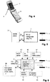
Fig. 4 ein erfindungsgemäss ausgestaltetes Mobiltelefon; -
Fig. 5 ein Schema zum Mobiltelefon vonFig. 4 ; -
Fig. 6 ein Schema eines Transmitters mit möglichen Ein- und Ausgabeeinheiten; -
Fig. 7 eine innere Struktur einer Transmitterelektronik; -
Fig. 8 eine Darstellung eines möglichen "End-of-Battery-Life"-Managements in einem Transmitter. - Das portable Gerät 1 gemäss
Figur 1 ist im dargestellten Beispiel im wesentlichen kartenförmig ausgestaltet und weist eine erste Elektrode 3 und eine zweite Elektrode 4 auf. Zwischen der ersten und der zweiten Elektrode befinden sich weitere Elemente, bspw. ein Kunststoffträger 5 mit integrierten und/oder aufgebrachten elektronischen Bauteilen und einem Batteriefach (in der Figur nicht gezeichnet). Die integrierten und/oder aufgebrachten elektronischen Bauteile können bspw. den ASIC zur Ansteuerung der Elektroden, einen EEPROM-Speicher, Leiterbahnstrukturen und/oder weitere Elemente beinhalten. Anstatt aus Kunststoff kann der Träger auch keramisch oder aus einem anderen Material sein, wichtig ist lediglich, dass die beiden Elektroden voneinander elektrisch isoliert sind. - Mindestens eine der Elektroden kann mindestens teilweise transparent sein, im gezeichneten Beispiel die erste Elektrode 3. Auf einer Oberseite des Kunststoffträgers 5 können in an sich bekannter Art Beschriftungen, Bilder etc. aufgebracht sein, die durch die transparente Elektrode hindurch sichtbar sind.
-
Figur 2 zeigt ein weiteres Ausführungsbeispiel. Der Transmitter 1 ist als so genannte "Smart Card Cover" ausgebildet. Smart Card Covers sind an sich bekannt. Sie sind als bspw. biegesteife, transparente Hülle ausgebildet, welche bspw. an einem Kleidungsstück befestigt werden kann und in welche eine Smart Card (d.h. ein kartenförmiges Medium mit Speicher- und Kommunikationsfunktionalität) einschiebbar ist. - Der Transmitter weist ein Fach für eine Batterie 6 sowie eine schematisch durch einen Chip 7 repräsentierte Ansteuerelektronik für die mindestens zum Teil transparenten Elektroden 3, 4 auf. Die Smart Card 11 ist in einen Luftspalt einschiebbar. Ein eventuelles Beschriftungsfeld 12 der Smart Card bleibt durch die transparente erste Elektrode 3 hindurch sichtbar.
-
Figur 3 zeigt eine Variante der Ausführungsform vonFigur 2 , in welcher die Smart Card (bzw. andere Bauteile einer von der Transmitterelektronik verschiedenen Applikation) gleichzeitig als RFID-Identifikationsmedium dient. Zusätzlich zu den vorstehend bereits beschriebenen Elementen sieht man schematisch die RFID-Antenne, die hier von einer der Elektroden - im gezeichneten Beispiel von der transparenten Elektrode 3 - nicht vollständig abgedeckt wird. Es hat sich jedoch gezeigt, dass im Falle von transparenten Elektroden - bspw. Elektroden aus ITO - die RFID-Kommunikation auch funktioniert, wenn anders als in der Figur dargestellt beide transparenten Elektroden die RFID-Antenne 15 vollständig abdecken, d.h. wenn die transparente Elektrode 3 die ganze in der Figur obere Fläche bedeckt. -
Figuren 4 und 5 betreffen ein als Mobiltelefon 31 ausgestaltetes erfindungsgemässes portables Gerät. Die erste Elektrode 3 ist in das Display integriert und mindestens im Displaybereich transparent, während die zweite Elektrode 4 wie in den vorstehenden Beispielen von Transmitterelektroden nicht notwendigerweise transparent ist. Die zweite Elektrode befindet sich auf einer Hinterseite des Mobiltelefons (bzw. wie im dargestellten Beispiel von dessen Klappdeckel oder von einem anderen Teil des Mobiltelefons) und kann ggf. auch durch ein leitfähiges Gehäuseteil gebildet sein. Sie ist in möglichst grossen, festen Abstand zur ersten Elektrode angeordnet. InFig. 5 ist sehr schematisch dargestellt, wie die Transmitterelektronik 7 mit der übrigen Mobiltelefon-Elektronik in Verbindung stehen kann: Das Mobiltelefon speist die Transmitterelektronik (3V), und es besteht eine Kommunikationsverbindung über eine I2C-Schnittstelle. - Durch die Integration der Transmitterelektronik 7 in ein Mobiltelefon und das Vorsehen einer Schnittstelle nach einer bevorzugten Ausführungsform der Erfindung können mehrere Funktionalitäten miteinander in einem portablen Gerät integriert werden. Möglich sind bspw.:
- Dynamische Veränderung des kapazitiv-resistiv übertragenen Datensignales. Das aktuelle Datensignal kann bspw. als PIN-Code verwendet werden, der beliebig oft verändert werden kann.
- Erhöhte Sicherheit kann ermöglicht werden, bspw. durch so genannte "rolling codes" oder andere an sich bekannte Mittel der sicheren Datenübertragung.
- Eine noch weiter erhöhte Sicherheit kann erwirkt werden, indem die UHF-Übertragungsmittel des Mobiltelefons (Bluetooth, 3G etc.) ins Informationsübertragungsprozedere einbezogen werden, bspw. als downlink. Das ermöglicht bspw. die Verwendung des an sich bekannten "Challenge-Response"-Systemes. Auch eine zentrale Einheit kann in die Kommunikation mit einbezogen werden und bspw. Zertifikate vergeben (Cerberus etc.)
- Das Mobiltelefon mit der Transmitterelektronik kann als Programmiergerät verwendet werden. Ein kontinuierlicher Datenstrom kann mit Hilfe der Transmitterelektronik zum Empfänger gesendet werden.
- Künftige Mobiltelefone werden möglicherweise mit NFC, RFID- oder lowpower-wireless (bspw. wie vertrieben unter dem Markennamen wibree™ (www.wibree.com) oder Ultra Low Power Bluetooth oder anderen Identifikationsstandards versehen sein. Durch die Verwendung der kapazitiv-resistiven Informationsübertragung kann eine solche Identifikationstechnologie in einer einzigen Vorrichtung integriert werden, und der Benutzer muss nicht notwendigerweise wissen, welche Technologie aktuell genutzt wird. Besonders interessant ist die Kombination mit dem erfindungsgemässen Ansatz unter anderem darum, weil bspw. die selektive kapazitiv-resistive Informationsübertragung einer möglicherweise kurzreichweitigen (<10m), berührungslosen unselektiven Informationsübertragung nachfolgen und mit dieser zusammenwirken kann.
- Eine Transmitterelektronk für ein Mobiltelefon kann standardmässig ausgestaltet sein und lässt sich ohne Weiteres in bestehende Mobilitelefonarchitekturen einfügen.
- Gemäss einem weiteren Aspekt der Erfindung ist die Ansteuerung der Transmitterelektroden mit einer Charge-Recovery und/oder Adiabatic Switching-Logik versehen. Auch sind wie vorstehend beschrieben die Elektroden möglichst weit voneinander entfernt, und die Dielektrizitätskonstante des Mediums/der Medien zwischen den Elektroden ist möglichst klein.
- Währenddem gemäss der
Figur 5 die Transmitterelektronik 7 in ein portables Gerät 31 integriert ist, oder zumindest zeitweise mit diesem kommunizieren kann, ist gemäss derFigur 6 dieselbe Transmitterelektronik 7 für einen "stand-alone" Betrieb mit zusätzlichen Ein/Ausgabeelementen konfiguriert. Die in derFigur 6 gezeigte I2C-Schnittstelle ist bei einem "stand-alone" Betrieb nur zeitweise mit einem Host-System 46 verbunden, beispielsweise um die Transmitterelektronik 7 zu konfigurieren. - Anhand von
Figur 6 werden noch weitere Aspekte beschrieben, die mit einem möglichst kleinen Stromverbrauch und/oder der Überwachung der Batterieladung im Zusammenhang stehen. Die in gepunkteten Kasten dargestellten Komponenten in der Figur sind optional und können einzeln oder in Kombination vorhanden sein. - Die Transmitterelektronik 7 gemäss
Figur 6 ist mit einer Ausgabeeinheit 41 verbunden, über die eine Statusanzeige der Batterieladung ermöglicht wird. Eine solche kann ein Leuchtdiode (LED) oder mehrere Leuchtdioden 41 aufweisen. Weiter kann ein Aktivitätsdetektor 44 vorhanden sein, welcher die Elektrodenansteuerung ausschaltet, wenn das portable Gerät 31 oder ein Träger des Transponderchips 7, beispielsweise ein Schlüssel oder eine Karte, nicht bewegt wird. - Als Alternative oder eventuell in Ergänzung dazu kann auch vorgesehen sein, dass die Transmitterelektronik nur aktiv wird, wenn ein Aufwecksignal, bspw. ein LF-(Low Frequency) Aufwecksignal detektiert wird. Eine entsprechende Detektionseinheit ist mit dem Bezugszeichen 45 versehen. Konfigurationen mit LF-Detektoren für das In-Betrieb-Setzen einer Schaltung sind an sich bereits bekannt.
- In der Figur ist noch ein Ein-Schalter 42 dargestellt. Ein solcher kann bspw. zum Einsatz kommen, wenn in einem "Low-Comfort-Mode" bei fast leerer Batterie die Elektronik automatisch ausgeschaltet wurde. Durch Betätigung des Schalters 42 wird die Elektronik für eine begrenzte Zeit wieder aktiviert. Ebenfalls dargestellt ist ein Ein-Aus-Schalter 43, durch welchen das ganze portable Gerät ausgeschaltet werden kann, wenn es nicht gebraucht wird. Im Falle einer Verbindung zu einem "Host-System" (bspw. einem Mobiltelefon 31) 46 ist unter Umständen das Management des Stromverbrauchs etwas weniger wichtig.
- Das "Ausschalten der Elektronik" schliesst nicht aus, dass einzelne Komponenten immer noch aktiv sind, bspw. der Zeitgeber. Mit "Ausschalten" ist ausdrücklich der Übergang in einen solchen teilaktiven "Schlaf"-Modus mitgemeint. Insbesondere ist in einem solchen Schlafmodus das Aussenden des Signals über die Elektroden unterbrochen.
-
Figur 7 zeigt die innere Struktur einer Transmitterelektronik 7 respektive eines ASIC in einer bevorzugten Ausführungsform der Erfindung. Der ASIC weist als Hauptelemente eine Kommunikationschnittstelle 61 zu einem I2C-Bus mit Leitungen SDA und SCL auf, einen nichtflüchtigen Speicher 62, einen Codierer 63, einen Modulator 64, und Ausgangstreiber 67. Vorzugsweise weist er zudem Clockschaltkreise 65, eine Steuerlogik 70 für die Ausgangstreiber 67 und eine Stromsparlogik 71 auf. Die Ausgangstreiber 67 weisen vorzugsweise unterschiedliche Ausgangstreiber 68, 69 auf, aus denen ein bestimmter Treiber entsprechend den Eigenschaften der verwendeten Elektroden ausgewählt werden kann. Der Modulator 64 weist einen Chipgenerator 66 auf, typischerweise ein "linear feedback shift register" (LFSR). - Die Funktion der einzelnen Elemente ist die folgende: Über die Kommunikationschnittstelle 61 sind zu übertragende Daten in die Transmitterelektronik 7 einlesbar, und sind Steuer- und Betriebsparameter der Transmitterelektronik 7 einstellbar (beispielsweise die Länge und die Parameter des LFSR). Die zu übertragenden Daten können im nichtflüchtigen Speicher 62 gespeichert werden, so dass die Transmitterelektronik 7 anschliessend von der Schnittstelle abgekoppelt werden und autonom betrieben werden kann. Die zu übertragenden Daten können aber auch in ein Nutzlastregister 73 geschrieben werden und anschliessend durch weitere Daten von der Kommunikationschnittstelle 61 überschrieben werden. Die Daten im Nutzlastregister 73 werden, solange ein Sendebetrieb der Transmitterelektronik 7 aktiv ist, codiert, moduliert und gesendet.
- Zur Codierung weist der Codierer 63 in an sich bekannter Weise eine Einheit zum Hinzufügen von redundanten Korrekturbits auf, und beispielsweise einen differentiellen Encoder. Der so erzeugte Code wird durch den Modulator 64 vorzugsweise ultrabreitbandig moduliert. In an sich bekannter Weise geschieht dies beispielsweise mittels einer pseudozufälligen Chip-Sequenz. Jedes Bit des zu übertragenden Codes wird mit im Zeitbereich mit einem aus mehreren Bits bestehenden Chip multipliziert oder XOR-verknüpft, wodurch sich das breitbandmodulierte Signal ergibt.
- Im Modulator 64 oder anschliessend an diesen kann noch ein Element vorhanden sein, mit dem die Bandbreite variiert werden kann. Dieses kann bspw. als Frequenzteiler (z.B. Flip-Flop) ausgebildet sein, der je nach Vorgabe die Signalübertragung mit voller Bandbreite oder mit reduzierter Bandbreite bewirkt, bspw. mit der halben Bandbreite.
- In einer bevorzugten Ausführungsform der Erfindung ist die Transmitterelektronik 7 derart ausgebildet, dass die Länge der Chip-Sequenz vorgebbar oder wählbar ist, beispielsweise durch Übergabe entsprechender Parameter über die Schnittstelle 61. Damit ist es möglich die an sich gegensätzlichen Anforderungen bezüglich Kommunikationssicherheit und -Geschwindigkeit entsprechend der Anwendung der 7 einzustellen.
- Ebenfalls ist möglich, durch Veränderungen einer Einstellung des Clock Multipliers die Mittenfrequenz (Carrierfrequenz) der Übertragung festzulegen - quasi durch eine Skalierung aller Frequenzen. So kann auch in Gegenwart von Störungen die Robustheit der Datenübertragung optimiert werden. Es kann beispielsweise vorgesehen sein, dass ein durch einen Schalter oder eine Mehrzahl von Schaltern die Mittenfrequenz zwischen diskreten Werten oder quasi-kontinuierlich geschaltet werden kann, oder dass ggf. über die Schnittstelle eine Vorgabe für die Mittenfrequenz als numerischen Wert gemacht werden und in einen entsprechenden Speicher abgelegt werden kann. Die Schaltzustände der Schalter können ggf. ebenfalls via die Schnittstelle definiert sein, oder sie können, insbesondere wenn keine Schnittstelle vorhanden ist, - bspw. in der Art von DIP-Schaltern - für einen Benutzer extern zugänglich sein, oder sie können bereits bei der Produktion des portablen Geräts bestimmt werden.
- Besonders günstig ist eine Kombination der Möglichkeiten, die Mittenfrequenz zwischen mindestens zwei Werten oder kontinuierlich zu varriieren und der Möglichkeit, die Bandbreite ebenfalls zwischen mindestens zwei Werten oder kontinuierlich zu variieren. Dadurch kann besonders effektiv auf das Vorhandensein eventueller Störsignale eingegangen werden.
- Die Steuerlogik 70 für die Ausgangstreiber 67 bestimmt die zu verwendenden Ausgangstreiber 68, 69 beispielsweise in folgender Weise: mit einem Steuersignal CL ist die Grössenordnung der kapazitiven Last der Elektroden 3, 4 wählbar. Mit einem Steuersignal DR_MD ist wählbar, ob die Elektroden differenziell oder singleended angesteuert werden. Mit einem Steuersignal PSO ist wählbar, ob die Elektroden mittels "synchronous rectification" angesteuert werden (wobei eine externe Beschaltung mittels einer oder zweier Induktivitäten erforderlich ist). Durch diese Steuersignale können die Ausgangstreiber 67 und ihre Betriebsart an die verwendeten Elektroden 3, 4 angepasst werden, so dass ihr Energiebedarf möglichst klein bleibt.
- Die Stromsparlogik 71 weist unter anderem die Detektion des Batteriezustands 74 und vorzugsweise die folgenden Eingänge auf
- ▪ PWR_BT und BT_PRE zum Einschalten und Ausschalten verschiedener Stufen eines stromsparenden Betriebs;
- ▪ LCM_BT zum Aktivieren des Aussendens von Signalen über die Elektroden 3, 4 (beispielsweise während einer vorgegebenen Zeit) wenn sich die Transmitterelektronik 7 im "low-comfort mode" befindet;
- ▪ MOT_DET1/2 für mindestens einen Bewegungsdetektor oder Aktivitätsdetektor (44); und
- ▪ WU EXT für ein externes, insbesondere drahtlos empfangenes Aufwachsignal ("Wake-Up"), beispielsweise von einem 125 kHz Empfänger. Damit kann erreicht werden, dass die Transmitterelektronik 7 nur in der Nähe eines Empfängers aktiviert wird. Dazu ist der Empfänger, der beispielsweise ortsfest ist oder in einem Auto eingebaut ist, mit einem entsprechenden 125 kHz Sender zum Aussenden eines Wake-Up-Signals ausgerüstet.
- Ausgangssignale LED1, LED2 steuern LEDs zur Anzeige des Batteriestatus an. Ausgangssignale EOL_HI, EOL_LO zeigen ebenfalls den Batterielevel an und können durch beispielsweise das portable Gerät 31 abgefragt und verarbeitet werden.
- In
Figur 8 schliesslich ist noch eine mögliche Ausführungsform eines "End-of-Battery-Life"-Verhaltens aufgezeigt. In der Figur sieht man eine typische Entladungskurve 51 einer Lithium-Ionen-Batterie und in Bezug darauf - den Bereich für den Normalbetrieb und mit Anzeige des Normal-Ladungszustandes, in welchem, bis zum Unterschreiten einer ersten Spannungsschwelle EOL1, das erste "End-of-Life"-Signal EOL_HI (Zeile Nr. 52) tief ist, und
- den gesamten Bereich für den Normalbetrieb, in welchem, bis zum Unterschreiten einer zweiten Spannungsschwelle EOL2, das zweite "End-of-Life"-Signal EOL_LO (Nr. 53) tief ist.
- In Zeilen 55 und 56 findet sich eine entsprechende Darstellung der Leuchtmoden: währenddem EOL_HI tief ist, leuchtet eine erste LED oder blinkt mit einem bestimmten Muster, nachdem EO1 unterschritten ist, blinkt die zweite LED mit einem bestimmten Muster.
- Zeile 54 zeigt die Aktivierung des "Low-Comfort-Mode-Bereichs" 54, in welchem das portable Gerät nur bei aktiver Betätigung, also durch Drücken einer Taste, sendet (d.h. man muss es aus der Tasche nehmen).
- Weiter ist dargestellt (Zeile 58), in welchen Zeiträumen die Elektroden aktiv sind, also senden. Dies ist im Normalbetrieb der Fall, wenn ein Aktivitätssensor eine Bewegung des portablen Geräts registriert, oder wenn ein Aufwachsignal empfangen wird (Nr. 57). Wenn die Bewegung aufhört, bleiben die Elektroden vorzugsweise noch während einer Zeitdauer t_del_sleep aktiv. Im "Low-Comfort-Mode" sind die Elektroden nur aktiv, wenn die entsprechende Taste betätigt wird (Nr. 59). Beim letzten Peak ganz rechts auf Zeile 58 wird also davon ausgegangen, dass eine aktive Aktivierung durch den Benutzer entsprechend Zeile 59 erfolgt ist.
Claims (6)
- Portables Gerät (1, 31) für die Übertragung von Signalen zur Datenübertragung an ein zweites Gerät, wobei das portable Gerät (31) durch einen Benutzer tragbar ist, aufweisend mindestens zwei Elektroden (3, 4) und Mittel zum Anlegen eines elektrischen Signals zwischen den Elektroden (3, 4), so dass das Signal durch die Elektroden (3, 4) in den Körper des Benutzers einkoppelbar und vom Körper durch mindestens eine Elektrode des zweiten Geräts detektierbar ist, dadurch gekennzeichnet, dass
die genannten Mittel (67) zum Anlegen des elektrischen Signals zwischen den Elektroden (3, 4) Teil einer Transmitterelektronik (7) sind,
die Transmitterelektronik (7) zudem Mittel (63, 64) zum Erzeugen des elektrischen Signals in Abhängigkeit von vorgegebenen Daten aufweist,
und die Transmitterelektronik (7) als anwendungsspezifischer Integrierter Schaltkreis (ASIC) ausgeführt ist.
dadurch gekennzeichnet, dass eine Kommunikationsverbindung zwischen der Transmitterelektronik (7) und einer Eingabeeinheit des portablen Gerätes (1; 31) besteht, wobei von der Transmitterlelektronik (7) übermittelte Signale von eingegebenen Daten abhängig sind, und das portable Gerät (1, 31) als Mobiltelefon ausgebildet ist, und die Eingabeeinheit des portablen Gerätes (1; 31) der Eingabeeinheit des Mobiltelefons entspricht. - Portables Gerät (1, 31) nach Anspruch 1, in welchem die Transmitterelektronik (7) einen Codierer (63) zum Codieren von zu übertragenden Daten und damit zur Erzeugung von codierten Daten, einen Modulator (64) zum Modulieren der codierten Daten und damit zur Erzeugung eines modulierten Signals, und einen Treiber (67) zum Verstärken des modulierten Signals und zum Ansteuern der Elektroden (3, 4) aufweist.
- Portables Gerät (1, 31) nach einem der Ansprüche 1 oder 2, wobei eine Kommunikationsverbindung zwischen der Transmitterelektronik (7) und einer Eingabeeinheit besteht oder herstellbar ist, insbesondere eine I2C-Schnittstelle (61), und die Transmitterelektronik (7) so ausgelegt und/oder programmiert ist, dass das elektrische Signal von über die Eingabeeinheit eingegebenen Daten abhängig ist.
- Portables Gerät (1, 31) nach einem der vorangehenden Ansprüche, wobei die Transmitterlektronik einen beispielsweise nichtflüchtigen Datenspeicher aufweist.
- Portables Gerät (1, 31) nach einem der vorangehenden Ansprüche, wobei zwischen den Elektroden Bauteile einer von der Transmitterelektronik (7) verschiedenen Applikation angeordnet sind.
- Verwendung eines portablen Geräts (1, 31) nach einem der Ansprüche 1 bis 5 für die Zugangskontrolle.
Applications Claiming Priority (2)
| Application Number | Priority Date | Filing Date | Title |
|---|---|---|---|
| CH2402007 | 2007-02-14 | ||
| PCT/CH2008/000059 WO2008098399A1 (de) | 2007-02-14 | 2008-02-14 | System und portables gerät für die übertragung von identifikationssignalen |
Publications (2)
| Publication Number | Publication Date |
|---|---|
| EP2127159A1 EP2127159A1 (de) | 2009-12-02 |
| EP2127159B1 true EP2127159B1 (de) | 2018-11-28 |
Family
ID=39431214
Family Applications (3)
| Application Number | Title | Priority Date | Filing Date |
|---|---|---|---|
| EP08700559A Withdrawn EP2127160A1 (de) | 2007-02-14 | 2008-02-14 | System und portables gerät für die übertragung von identifikationssignalen |
| EP08706359.0A Not-in-force EP2127159B1 (de) | 2007-02-14 | 2008-02-14 | System und portables gerät für die übertragung von identifikationssignalen |
| EP08700560A Ceased EP2127161A2 (de) | 2007-02-14 | 2008-02-14 | System und portables gerät für die übertragung von identifikationssignalen |
Family Applications Before (1)
| Application Number | Title | Priority Date | Filing Date |
|---|---|---|---|
| EP08700559A Withdrawn EP2127160A1 (de) | 2007-02-14 | 2008-02-14 | System und portables gerät für die übertragung von identifikationssignalen |
Family Applications After (1)
| Application Number | Title | Priority Date | Filing Date |
|---|---|---|---|
| EP08700560A Ceased EP2127161A2 (de) | 2007-02-14 | 2008-02-14 | System und portables gerät für die übertragung von identifikationssignalen |
Country Status (4)
| Country | Link |
|---|---|
| US (3) | US8798531B2 (de) |
| EP (3) | EP2127160A1 (de) |
| JP (3) | JP5224546B2 (de) |
| WO (3) | WO2008098398A2 (de) |
Families Citing this family (47)
| Publication number | Priority date | Publication date | Assignee | Title |
|---|---|---|---|---|
| US10068167B2 (en) * | 2002-07-09 | 2018-09-04 | Smartrac Technology Fletcher, Inc. | Transparent radio frequency identification transponder |
| US8798531B2 (en) * | 2007-02-14 | 2014-08-05 | Kaba Ag | System and portable device for transmitting identification signals |
| EP2304693B1 (de) * | 2008-06-18 | 2016-08-31 | Kaba AG | Zugangskontrollverfahren und zugangskontrollsystem |
| JP4616379B2 (ja) * | 2008-09-24 | 2011-01-19 | 日本電信電話株式会社 | 携帯電話機 |
| US8305195B2 (en) * | 2008-09-30 | 2012-11-06 | Getac Technology Corp. | Radio frequency identification communication system and method thereof |
| JP2010109801A (ja) * | 2008-10-31 | 2010-05-13 | Alps Electric Co Ltd | 通信装置 |
| CN102301402A (zh) * | 2008-12-12 | 2011-12-28 | 博斯艾迪公司 | 访问识别和控制设备 |
| FR2942755B1 (fr) * | 2009-03-03 | 2011-07-15 | Continental Automotive France | Procede d'identification d'un individu en vue d'autoriser une action commandee par un organe d'actionnement |
| WO2010109698A1 (ja) * | 2009-03-26 | 2010-09-30 | アルプス電気株式会社 | 通信システム |
| US20100321159A1 (en) * | 2009-06-18 | 2010-12-23 | Authentec, Inc. | Touch based data communication using biometric finger sensor and associated methods |
| US9134534B2 (en) | 2010-02-28 | 2015-09-15 | Microsoft Technology Licensing, Llc | See-through near-eye display glasses including a modular image source |
| US8472120B2 (en) | 2010-02-28 | 2013-06-25 | Osterhout Group, Inc. | See-through near-eye display glasses with a small scale image source |
| US10180572B2 (en) | 2010-02-28 | 2019-01-15 | Microsoft Technology Licensing, Llc | AR glasses with event and user action control of external applications |
| US9182596B2 (en) | 2010-02-28 | 2015-11-10 | Microsoft Technology Licensing, Llc | See-through near-eye display glasses with the optical assembly including absorptive polarizers or anti-reflective coatings to reduce stray light |
| US20150309316A1 (en) | 2011-04-06 | 2015-10-29 | Microsoft Technology Licensing, Llc | Ar glasses with predictive control of external device based on event input |
| US9759917B2 (en) | 2010-02-28 | 2017-09-12 | Microsoft Technology Licensing, Llc | AR glasses with event and sensor triggered AR eyepiece interface to external devices |
| US9129295B2 (en) | 2010-02-28 | 2015-09-08 | Microsoft Technology Licensing, Llc | See-through near-eye display glasses with a fast response photochromic film system for quick transition from dark to clear |
| US20120249797A1 (en) | 2010-02-28 | 2012-10-04 | Osterhout Group, Inc. | Head-worn adaptive display |
| US9285589B2 (en) | 2010-02-28 | 2016-03-15 | Microsoft Technology Licensing, Llc | AR glasses with event and sensor triggered control of AR eyepiece applications |
| US8482859B2 (en) | 2010-02-28 | 2013-07-09 | Osterhout Group, Inc. | See-through near-eye display glasses wherein image light is transmitted to and reflected from an optically flat film |
| AU2011220382A1 (en) | 2010-02-28 | 2012-10-18 | Microsoft Corporation | Local advertising content on an interactive head-mounted eyepiece |
| US9366862B2 (en) | 2010-02-28 | 2016-06-14 | Microsoft Technology Licensing, Llc | System and method for delivering content to a group of see-through near eye display eyepieces |
| US9341843B2 (en) | 2010-02-28 | 2016-05-17 | Microsoft Technology Licensing, Llc | See-through near-eye display glasses with a small scale image source |
| US9128281B2 (en) | 2010-09-14 | 2015-09-08 | Microsoft Technology Licensing, Llc | Eyepiece with uniformly illuminated reflective display |
| US8488246B2 (en) | 2010-02-28 | 2013-07-16 | Osterhout Group, Inc. | See-through near-eye display glasses including a curved polarizing film in the image source, a partially reflective, partially transmitting optical element and an optically flat film |
| US9097891B2 (en) | 2010-02-28 | 2015-08-04 | Microsoft Technology Licensing, Llc | See-through near-eye display glasses including an auto-brightness control for the display brightness based on the brightness in the environment |
| US9229227B2 (en) | 2010-02-28 | 2016-01-05 | Microsoft Technology Licensing, Llc | See-through near-eye display glasses with a light transmissive wedge shaped illumination system |
| US8477425B2 (en) | 2010-02-28 | 2013-07-02 | Osterhout Group, Inc. | See-through near-eye display glasses including a partially reflective, partially transmitting optical element |
| US9091851B2 (en) | 2010-02-28 | 2015-07-28 | Microsoft Technology Licensing, Llc | Light control in head mounted displays |
| US9223134B2 (en) | 2010-02-28 | 2015-12-29 | Microsoft Technology Licensing, Llc | Optical imperfections in a light transmissive illumination system for see-through near-eye display glasses |
| US9097890B2 (en) | 2010-02-28 | 2015-08-04 | Microsoft Technology Licensing, Llc | Grating in a light transmissive illumination system for see-through near-eye display glasses |
| US8467133B2 (en) | 2010-02-28 | 2013-06-18 | Osterhout Group, Inc. | See-through display with an optical assembly including a wedge-shaped illumination system |
| KR101657314B1 (ko) * | 2010-06-29 | 2016-09-19 | 삼성전자주식회사 | 근거리 무선통신을 이용한 오디오 제어 시스템 및 방법 |
| JP2012053520A (ja) * | 2010-08-31 | 2012-03-15 | Nippon Signal Co Ltd:The | 入退場管理システムおよび人体通信ユニット |
| US8184983B1 (en) | 2010-11-12 | 2012-05-22 | Google Inc. | Wireless directional identification and subsequent communication between wearable electronic devices |
| US8430310B1 (en) | 2011-05-24 | 2013-04-30 | Google Inc. | Wireless directional identification and verification using wearable electronic devices |
| US20140340340A1 (en) * | 2011-09-13 | 2014-11-20 | Hsiung-Kuang Tsai | Visual interface system |
| KR101584107B1 (ko) * | 2011-10-10 | 2016-01-12 | 로슈티슬라브 보로뒤미로비취 보센코 | 송신 장치와 수신 장치 사이에서 데이터 스트림을 무선으로 송신하기 위한 무선 송신 시스템 및 방법, 신호 무선 수신 방법, 데이터 스트림을 무선으로 송신하기 위한 송신 장치 및 수신 데이터 스트림을 생성할 수 있도록 두 개의 전기 신호들을 무선으로 수신하기 위한 수신 장치 |
| EP2677406B1 (de) | 2012-06-18 | 2018-09-05 | Wincor Nixdorf International GmbH | Baugruppe mit einer Anzeigevorrichtung und einer Nahfeldkommunikationseinheit |
| US9135548B2 (en) * | 2012-11-29 | 2015-09-15 | Paypal, Inc. | Portable mechanical switch for selective deactivation of radio frequency identification circuits |
| FR3007599B1 (fr) * | 2013-06-24 | 2016-11-11 | Inside Secure | Dispositif portable comprenant une electrode de transmission de donnees par courant intracorporel |
| FR3007598B1 (fr) * | 2013-06-24 | 2015-07-17 | Inside Secure | Dispositif portable comprenant des moyens de transmission de donnees par couplage inductif et courant intracorporel |
| EP3014793B1 (de) * | 2013-06-24 | 2017-08-02 | Inside Secure | Tragbare vorrichtung mit mitteln zum übertragen von daten mit induktiver kopplung und intrakorporalem strom |
| GB2518160A (en) * | 2013-09-11 | 2015-03-18 | British Airways Plc | Identification apparatus and method |
| CN104916010A (zh) * | 2014-03-13 | 2015-09-16 | 北京弘天智达科技有限公司 | 移动设备的控制系统和穿戴式控制设备 |
| US10600928B1 (en) * | 2016-09-20 | 2020-03-24 | Apple Inc. | Systems with photovoltaic cells |
| CN108811181A (zh) * | 2018-04-27 | 2018-11-13 | 努比亚技术有限公司 | 智能穿戴设备、防盗控制方法及计算机可读存储介质 |
Family Cites Families (67)
| Publication number | Priority date | Publication date | Assignee | Title |
|---|---|---|---|---|
| EP0109184A3 (de) * | 1982-10-12 | 1985-07-24 | Roundel Electronics Limited | Identifikationsverfahren |
| US7020125B2 (en) * | 1990-12-05 | 2006-03-28 | Interdigital Technology Corporation | Broadband CDMA overlay system and method |
| US5366443A (en) * | 1992-01-07 | 1994-11-22 | Thapliyal And Eggers Partners | Method and apparatus for advancing catheters through occluded body lumens |
| DE4329898A1 (de) * | 1993-09-04 | 1995-04-06 | Marcus Dr Besson | Kabelloses medizinisches Diagnose- und Überwachungsgerät |
| JP4074661B2 (ja) * | 1995-05-08 | 2008-04-09 | マサチューセッツ・インスティテュート・オブ・テクノロジー | 信号伝送媒体として人体を用いた非接触検知及び信号システム |
| US5721783A (en) * | 1995-06-07 | 1998-02-24 | Anderson; James C. | Hearing aid with wireless remote processor |
| DE19547560C2 (de) * | 1995-12-20 | 2000-01-13 | Daimler Chrysler Ag | Einrichtung zur körpergebundenen Datenübertragung zwischen zwei Endgeräten |
| DE19610086C2 (de) * | 1996-03-14 | 2000-02-17 | Siemens Ag | Verfahren und Anordnung zum Abwickeln von Protokollen zwischen Telekommunikationsgeräten drahtloser Telekommunikationssysteme |
| US5796827A (en) * | 1996-11-14 | 1998-08-18 | International Business Machines Corporation | System and method for near-field human-body coupling for encrypted communication with identification cards |
| US6223018B1 (en) * | 1996-12-12 | 2001-04-24 | Nippon Telegraph And Telephone Corporation | Intra-body information transfer device |
| US6128122A (en) * | 1998-09-18 | 2000-10-03 | Seagate Technology, Inc. | Micromachined mirror with stretchable restoring force member |
| US5999561A (en) * | 1997-05-20 | 1999-12-07 | Sanconix, Inc. | Direct sequence spread spectrum method, computer-based product, apparatus and system tolerant to frequency reference offset |
| US6211799B1 (en) * | 1997-11-06 | 2001-04-03 | Massachusetts Institute Of Technology | Method and apparatus for transbody transmission of power and information |
| EP1901251B1 (de) * | 1998-08-14 | 2010-09-29 | 3M Innovative Properties Company | Anwendungen für Funkfrequenzinformationssysteme |
| US6867752B1 (en) * | 1998-08-31 | 2005-03-15 | Semiconductor Energy Laboratory Co., Ltd. | Portable information processing system |
| EP1045947B1 (de) * | 1998-09-14 | 2005-01-26 | Koninklijke Philips Electronics N.V. | Elektronisches kommunikationssystem |
| US6336031B1 (en) * | 1998-12-22 | 2002-01-01 | Nortel Networks Limited | Wireless data transmission over quasi-static electric potential fields |
| WO2001071434A1 (en) * | 2000-03-21 | 2001-09-27 | Citizen Watch Co., Ltd. | Electronic unit |
| US6754472B1 (en) * | 2000-04-27 | 2004-06-22 | Microsoft Corporation | Method and apparatus for transmitting power and data using the human body |
| JP3319462B2 (ja) * | 2000-06-26 | 2002-09-03 | 松下電工株式会社 | 信号伝送経路として人体を利用したデータ伝送システム |
| EP1168678B1 (de) * | 2000-06-27 | 2003-09-03 | Matsushita Electric Works, Ltd. | Datenübertragungssystem unter Verwendung eines menschlichen Körpers als Signalübertragungsweg |
| DE60102331T2 (de) * | 2000-09-08 | 2005-03-17 | Matsushita Electric Works, Ltd., Kadoma | Datenübertragungssystem unter Verwendung eines menschlichen Körpers als Signalübertragungsweg |
| US6781570B1 (en) * | 2000-11-09 | 2004-08-24 | Logitech Europe S.A. | Wireless optical input device |
| FI110560B (fi) * | 2000-12-27 | 2003-02-14 | Nokia Corp | Ryhmän muodostaminen langattomille kommunikaatiopäätelaitteille |
| JP4460784B2 (ja) * | 2001-01-31 | 2010-05-12 | シャープ株式会社 | 液晶表示装置 |
| EP1271998B1 (de) * | 2001-06-28 | 2008-04-16 | Matsushita Electric Industrial Co., Ltd. | Lautsprechersystem, Mobilendgerät und elektronische Vorrichtung |
| DE60238447D1 (de) * | 2002-03-26 | 2011-01-05 | Nokia Corp | Vorrichtung, verfahren und system zur authentisierung |
| JP3940026B2 (ja) * | 2002-05-23 | 2007-07-04 | アルプス電気株式会社 | 電子回路ユニットの製造方法 |
| RU2224275C1 (ru) * | 2002-09-26 | 2004-02-20 | Закрытое акционерное общество "ТехноГласс Инжиниринг" | Способ изготовления электрохромного устройства и электрохромное устройство |
| US7352355B2 (en) * | 2002-10-28 | 2008-04-01 | Delphi Technologies, Inc. | Transparent overlay input device |
| US8155586B2 (en) * | 2003-01-25 | 2012-04-10 | Korea Institute Of Science And Technology | Method and system for data communication using a body |
| KR100873683B1 (ko) * | 2003-01-25 | 2008-12-12 | 한국과학기술연구원 | 인체통신방법, 인체통신시스템 및 이에 사용되는 캡슐형 내시경 |
| JP4156531B2 (ja) * | 2003-02-03 | 2008-09-24 | 富士フイルム株式会社 | 通信機器 |
| AU2003904170A0 (en) * | 2003-08-08 | 2003-08-21 | Clipsal Intergrated Systems Pty Ltd | Radio network communication system and protocol |
| JP2005159684A (ja) | 2003-11-25 | 2005-06-16 | Matsushita Electric Works Ltd | 通信システム |
| WO2005078425A1 (en) * | 2004-02-04 | 2005-08-25 | The Johns Hopkins University | Methods and systems for producing arrays of particles |
| US8095813B2 (en) * | 2004-03-22 | 2012-01-10 | Integrated Device Technology, Inc | Integrated circuit systems having processor-controlled clock signal generators therein that support efficient power management |
| JP2005284511A (ja) * | 2004-03-29 | 2005-10-13 | Matsushita Electric Ind Co Ltd | 挿入型無線通信媒体装置および電子機器 |
| CA2462495A1 (en) * | 2004-03-30 | 2005-09-30 | Dspfactory Ltd. | Method and system for protecting content in a programmable system |
| JP4028513B2 (ja) | 2004-04-09 | 2007-12-26 | 日本電信電話株式会社 | 通信システム |
| JP4509649B2 (ja) * | 2004-05-24 | 2010-07-21 | パナソニック株式会社 | プラズマディスプレイ装置 |
| JP2005341312A (ja) * | 2004-05-27 | 2005-12-08 | Matsushita Electric Works Ltd | データ通信装置及び通信システム |
| US20060020469A1 (en) * | 2004-07-08 | 2006-01-26 | Rast Rodger H | Apparatus and methods for static and semi-static displays |
| DE102004044375A1 (de) * | 2004-09-10 | 2006-03-16 | Daimlerchrysler Ag | Vorrichtung zum Ver- und/oder Entriegeln einer Fahrzeugtür mit einem elektronischen Zugangsberechtigungssystem |
| WO2006054706A1 (ja) | 2004-11-19 | 2006-05-26 | Matsushita Electric Industrial Co., Ltd. | データ通信装置 |
| JP4865733B2 (ja) * | 2005-02-17 | 2012-02-01 | コーニンクレッカ フィリップス エレクトロニクス エヌ ヴィ | ネットワーク内で動作させられることのできる装置、ネットワーク・システム、ネットワーク内で装置を動作させる方法、プログラム要素およびコンピュータ可読媒体 |
| CA2592749C (en) * | 2005-03-24 | 2015-02-24 | Privaris, Inc. | Biometric identification device with smartcard capabilities |
| JP4586618B2 (ja) * | 2005-04-18 | 2010-11-24 | ソニー株式会社 | 人体通信システム及び通信装置 |
| CN102379684B (zh) * | 2005-04-28 | 2014-11-19 | 普罗透斯数字保健公司 | 药物信息系统 |
| JP4692069B2 (ja) * | 2005-05-10 | 2011-06-01 | 沖電気工業株式会社 | データ入力装置および携帯型データ通信装置 |
| JP4257611B2 (ja) * | 2005-05-17 | 2009-04-22 | ソニー株式会社 | 通信装置および方法、並びにプログラム |
| JP2006352700A (ja) * | 2005-06-17 | 2006-12-28 | Sony Corp | 通信システム、通信装置および方法、並びにプログラム |
| JP4544080B2 (ja) | 2005-07-25 | 2010-09-15 | ソニー株式会社 | 通信装置および方法、並びにプログラム |
| WO2007030699A1 (en) * | 2005-09-08 | 2007-03-15 | Sri International | Rfid tags having ferromagnetic patches |
| TW200727609A (en) | 2005-09-27 | 2007-07-16 | Kaba Ag | A method and system for the transmission of identification signals |
| CA2648128A1 (en) | 2006-04-03 | 2007-10-11 | Kaba Ag | Method and system for information transmission |
| US7832645B2 (en) * | 2006-04-10 | 2010-11-16 | Kingston Technology Corporation | Flash memory card expander |
| EP2057763A1 (de) * | 2006-08-29 | 2009-05-13 | Nokia Corporation | Verwendung von körperinterner kommunikation |
| JP4893483B2 (ja) * | 2006-09-11 | 2012-03-07 | ソニー株式会社 | 通信システム |
| GB0621738D0 (en) * | 2006-10-31 | 2006-12-13 | Nanotecture Ltd | Electrochemical cell for use in smart cards |
| EP1942468A1 (de) * | 2007-01-03 | 2008-07-09 | Actividentity Inc. | Konfigurierbarer Halter für digitale Schilder |
| US7777719B2 (en) * | 2007-01-19 | 2010-08-17 | Nokia Corporation | System using a living body as a transmission medium |
| US8798531B2 (en) * | 2007-02-14 | 2014-08-05 | Kaba Ag | System and portable device for transmitting identification signals |
| CN101663846B (zh) * | 2007-04-20 | 2013-09-25 | 阿尔卑斯电气株式会社 | 通信设备、接收机及发送机 |
| CN101620454A (zh) * | 2008-07-04 | 2010-01-06 | 清华大学 | 便携式电脑 |
| KR101383258B1 (ko) * | 2007-11-08 | 2014-04-08 | 삼성전자주식회사 | 이동통신 시스템에서 인체 통신 기능을 제공하기 위한 장치및 방법 |
| JP4717141B2 (ja) * | 2007-12-26 | 2011-07-06 | アルプス電気株式会社 | 携帯機器 |
-
2008
- 2008-02-14 US US12/526,882 patent/US8798531B2/en not_active Expired - Fee Related
- 2008-02-14 EP EP08700559A patent/EP2127160A1/de not_active Withdrawn
- 2008-02-14 US US12/526,873 patent/US20100231353A1/en not_active Abandoned
- 2008-02-14 EP EP08706359.0A patent/EP2127159B1/de not_active Not-in-force
- 2008-02-14 WO PCT/CH2008/000058 patent/WO2008098398A2/de not_active Ceased
- 2008-02-14 US US12/526,868 patent/US20100144268A1/en not_active Abandoned
- 2008-02-14 EP EP08700560A patent/EP2127161A2/de not_active Ceased
- 2008-02-14 JP JP2009549756A patent/JP5224546B2/ja not_active Expired - Fee Related
- 2008-02-14 WO PCT/CH2008/000057 patent/WO2008098397A1/de not_active Ceased
- 2008-02-14 JP JP2009549757A patent/JP5273871B2/ja not_active Expired - Fee Related
- 2008-02-14 JP JP2009549755A patent/JP2010518789A/ja active Pending
- 2008-02-14 WO PCT/CH2008/000059 patent/WO2008098399A1/de not_active Ceased
Non-Patent Citations (1)
| Title |
|---|
| None * |
Also Published As
| Publication number | Publication date |
|---|---|
| US20100231353A1 (en) | 2010-09-16 |
| WO2008098399A1 (de) | 2008-08-21 |
| JP2010518789A (ja) | 2010-05-27 |
| JP5224546B2 (ja) | 2013-07-03 |
| WO2008098397A1 (de) | 2008-08-21 |
| JP2010518790A (ja) | 2010-05-27 |
| US20100048127A1 (en) | 2010-02-25 |
| EP2127159A1 (de) | 2009-12-02 |
| WO2008098398A2 (de) | 2008-08-21 |
| JP5273871B2 (ja) | 2013-08-28 |
| US20100144268A1 (en) | 2010-06-10 |
| WO2008098398A3 (de) | 2008-12-04 |
| EP2127161A2 (de) | 2009-12-02 |
| EP2127160A1 (de) | 2009-12-02 |
| JP2010521079A (ja) | 2010-06-17 |
| US8798531B2 (en) | 2014-08-05 |
Similar Documents
| Publication | Publication Date | Title |
|---|---|---|
| EP2127159A1 (de) | System und portables gerät für die übertragung von identifikationssignalen | |
| EP2284773B2 (de) | Chipkarte | |
| EP0502518B1 (de) | Verfahren zur drahtlosen Übertragung von Daten auf einen Datensträger | |
| EP1583415B1 (de) | Energieautarker sensor | |
| EP1801741B1 (de) | Tragbarer Datenträger mit aktiver Kontaktlosschnittstelle | |
| DE60207122T2 (de) | Informationsverarbeitungsvorrichtung und kartenförmiges Informationsverarbeitungsgerät | |
| DE102015108867A1 (de) | Handyhüllen-Wagenschlüsselanhänger | |
| EP1782330A1 (de) | Gesteuertes kontaktloses aufladen eines akkumulators in einer chipkarte | |
| DE112008001187T5 (de) | Energie- und Zeitverwaltung in einem Smartcard-Gerät | |
| EP4697855A2 (de) | Elektronisches regaletiketten-system mit standardisiertem funk-kommunikationsprotokoll | |
| DE102004039651A1 (de) | Gesteuertes kontaktloses Aufladen eines Akkumulators | |
| EP3586272B1 (de) | Bidirektionaler transponder mit geringem energieverbrauch | |
| EP2871616B1 (de) | Verfahren und Vorrichtung zur Zutrittskontrolle | |
| EP3482374B1 (de) | Mobile funkeinheit für ein fahrzeugschliesssystem | |
| DE102004039650A1 (de) | Flexibles kontaktloses Aufladen eines Akkumulators | |
| WO2001015061A2 (de) | Chipkarte für kontaktlose energieversorgung und kontaktloses transpondersystem mit einer chipkarte | |
| EP1899903A2 (de) | Schaltungseinrichtung zur abwicklung eines datentransfers | |
| DE102005017805B4 (de) | Tragbare Vorrichtung für Steuersystem von Fahrzeugvorrichtungen | |
| DE102004039648A1 (de) | Benutzersignal bei kontaktlosem Aufladen eines Akkumulators | |
| EP1469421A1 (de) | Tragbarer Datenträger und Verfahren zur Kommunikation mit einem tragbaren Datenträger | |
| DE102018132421A1 (de) | Handsender zur fernsteuerbaren Auslösung eines technischen Ereignisses, insbesondere Zutrittsbuchung, Zeitbuchung oder Türöffnung | |
| EP1906363A1 (de) | Zugangskontrollsystem | |
| DE102010027135A1 (de) | Tragbarer Datenträger, insbesondere Chipkarte |
Legal Events
| Date | Code | Title | Description |
|---|---|---|---|
| PUAI | Public reference made under article 153(3) epc to a published international application that has entered the european phase |
Free format text: ORIGINAL CODE: 0009012 |
|
| 17P | Request for examination filed |
Effective date: 20090807 |
|
| AK | Designated contracting states |
Kind code of ref document: A1 Designated state(s): AT BE BG CH CY CZ DE DK EE ES FI FR GB GR HR HU IE IS IT LI LT LU LV MC MT NL NO PL PT RO SE SI SK TR |
|
| DAX | Request for extension of the european patent (deleted) | ||
| 17Q | First examination report despatched |
Effective date: 20140722 |
|
| 17Q | First examination report despatched |
Effective date: 20140728 |
|
| 17Q | First examination report despatched |
Effective date: 20140801 |
|
| 17Q | First examination report despatched |
Effective date: 20140807 |
|
| 17Q | First examination report despatched |
Effective date: 20140813 |
|
| 17Q | First examination report despatched |
Effective date: 20140825 |
|
| 17Q | First examination report despatched |
Effective date: 20140829 |
|
| 17Q | First examination report despatched |
Effective date: 20140904 |
|
| STAA | Information on the status of an ep patent application or granted ep patent |
Free format text: STATUS: EXAMINATION IS IN PROGRESS |
|
| RAP1 | Party data changed (applicant data changed or rights of an application transferred) |
Owner name: DORMAKABA SCHWEIZ AG |
|
| GRAP | Despatch of communication of intention to grant a patent |
Free format text: ORIGINAL CODE: EPIDOSNIGR1 |
|
| STAA | Information on the status of an ep patent application or granted ep patent |
Free format text: STATUS: GRANT OF PATENT IS INTENDED |
|
| INTG | Intention to grant announced |
Effective date: 20180622 |
|
| GRAS | Grant fee paid |
Free format text: ORIGINAL CODE: EPIDOSNIGR3 |
|
| GRAA | (expected) grant |
Free format text: ORIGINAL CODE: 0009210 |
|
| STAA | Information on the status of an ep patent application or granted ep patent |
Free format text: STATUS: THE PATENT HAS BEEN GRANTED |
|
| AK | Designated contracting states |
Kind code of ref document: B1 Designated state(s): AT BE BG CH CY CZ DE DK EE ES FI FR GB GR HR HU IE IS IT LI LT LU LV MC MT NL NO PL PT RO SE SI SK TR |
|
| REG | Reference to a national code |
Ref country code: GB Ref legal event code: FG4D Free format text: NOT ENGLISH |
|
| REG | Reference to a national code |
Ref country code: CH Ref legal event code: EP |
|
| REG | Reference to a national code |
Ref country code: AT Ref legal event code: REF Ref document number: 1071483 Country of ref document: AT Kind code of ref document: T Effective date: 20181215 |
|
| REG | Reference to a national code |
Ref country code: DE Ref legal event code: R096 Ref document number: 502008016479 Country of ref document: DE |
|
| REG | Reference to a national code |
Ref country code: IE Ref legal event code: FG4D Free format text: LANGUAGE OF EP DOCUMENT: GERMAN |
|
| REG | Reference to a national code |
Ref country code: CH Ref legal event code: NV Representative=s name: RENTSCH PARTNER AG, CH |
|
| REG | Reference to a national code |
Ref country code: SE Ref legal event code: TRGR |
|
| REG | Reference to a national code |
Ref country code: LT Ref legal event code: MG4D Ref country code: NL Ref legal event code: FP |
|
| PG25 | Lapsed in a contracting state [announced via postgrant information from national office to epo] |
Ref country code: LV Free format text: LAPSE BECAUSE OF FAILURE TO SUBMIT A TRANSLATION OF THE DESCRIPTION OR TO PAY THE FEE WITHIN THE PRESCRIBED TIME-LIMIT Effective date: 20181128 Ref country code: ES Free format text: LAPSE BECAUSE OF FAILURE TO SUBMIT A TRANSLATION OF THE DESCRIPTION OR TO PAY THE FEE WITHIN THE PRESCRIBED TIME-LIMIT Effective date: 20181128 Ref country code: NO Free format text: LAPSE BECAUSE OF FAILURE TO SUBMIT A TRANSLATION OF THE DESCRIPTION OR TO PAY THE FEE WITHIN THE PRESCRIBED TIME-LIMIT Effective date: 20190228 Ref country code: IS Free format text: LAPSE BECAUSE OF FAILURE TO SUBMIT A TRANSLATION OF THE DESCRIPTION OR TO PAY THE FEE WITHIN THE PRESCRIBED TIME-LIMIT Effective date: 20190328 Ref country code: HR Free format text: LAPSE BECAUSE OF FAILURE TO SUBMIT A TRANSLATION OF THE DESCRIPTION OR TO PAY THE FEE WITHIN THE PRESCRIBED TIME-LIMIT Effective date: 20181128 Ref country code: FI Free format text: LAPSE BECAUSE OF FAILURE TO SUBMIT A TRANSLATION OF THE DESCRIPTION OR TO PAY THE FEE WITHIN THE PRESCRIBED TIME-LIMIT Effective date: 20181128 Ref country code: LT Free format text: LAPSE BECAUSE OF FAILURE TO SUBMIT A TRANSLATION OF THE DESCRIPTION OR TO PAY THE FEE WITHIN THE PRESCRIBED TIME-LIMIT Effective date: 20181128 Ref country code: BG Free format text: LAPSE BECAUSE OF FAILURE TO SUBMIT A TRANSLATION OF THE DESCRIPTION OR TO PAY THE FEE WITHIN THE PRESCRIBED TIME-LIMIT Effective date: 20190228 |
|
| PG25 | Lapsed in a contracting state [announced via postgrant information from national office to epo] |
Ref country code: PT Free format text: LAPSE BECAUSE OF FAILURE TO SUBMIT A TRANSLATION OF THE DESCRIPTION OR TO PAY THE FEE WITHIN THE PRESCRIBED TIME-LIMIT Effective date: 20190328 Ref country code: GR Free format text: LAPSE BECAUSE OF FAILURE TO SUBMIT A TRANSLATION OF THE DESCRIPTION OR TO PAY THE FEE WITHIN THE PRESCRIBED TIME-LIMIT Effective date: 20190301 |
|
| PG25 | Lapsed in a contracting state [announced via postgrant information from national office to epo] |
Ref country code: CZ Free format text: LAPSE BECAUSE OF FAILURE TO SUBMIT A TRANSLATION OF THE DESCRIPTION OR TO PAY THE FEE WITHIN THE PRESCRIBED TIME-LIMIT Effective date: 20181128 Ref country code: DK Free format text: LAPSE BECAUSE OF FAILURE TO SUBMIT A TRANSLATION OF THE DESCRIPTION OR TO PAY THE FEE WITHIN THE PRESCRIBED TIME-LIMIT Effective date: 20181128 Ref country code: IT Free format text: LAPSE BECAUSE OF FAILURE TO SUBMIT A TRANSLATION OF THE DESCRIPTION OR TO PAY THE FEE WITHIN THE PRESCRIBED TIME-LIMIT Effective date: 20181128 Ref country code: PL Free format text: LAPSE BECAUSE OF FAILURE TO SUBMIT A TRANSLATION OF THE DESCRIPTION OR TO PAY THE FEE WITHIN THE PRESCRIBED TIME-LIMIT Effective date: 20181128 |
|
| REG | Reference to a national code |
Ref country code: DE Ref legal event code: R097 Ref document number: 502008016479 Country of ref document: DE |
|
| PG25 | Lapsed in a contracting state [announced via postgrant information from national office to epo] |
Ref country code: EE Free format text: LAPSE BECAUSE OF FAILURE TO SUBMIT A TRANSLATION OF THE DESCRIPTION OR TO PAY THE FEE WITHIN THE PRESCRIBED TIME-LIMIT Effective date: 20181128 Ref country code: SK Free format text: LAPSE BECAUSE OF FAILURE TO SUBMIT A TRANSLATION OF THE DESCRIPTION OR TO PAY THE FEE WITHIN THE PRESCRIBED TIME-LIMIT Effective date: 20181128 Ref country code: RO Free format text: LAPSE BECAUSE OF FAILURE TO SUBMIT A TRANSLATION OF THE DESCRIPTION OR TO PAY THE FEE WITHIN THE PRESCRIBED TIME-LIMIT Effective date: 20181128 |
|
| PLBE | No opposition filed within time limit |
Free format text: ORIGINAL CODE: 0009261 |
|
| STAA | Information on the status of an ep patent application or granted ep patent |
Free format text: STATUS: NO OPPOSITION FILED WITHIN TIME LIMIT |
|
| GBPC | Gb: european patent ceased through non-payment of renewal fee |
Effective date: 20190228 |
|
| PG25 | Lapsed in a contracting state [announced via postgrant information from national office to epo] |
Ref country code: SI Free format text: LAPSE BECAUSE OF FAILURE TO SUBMIT A TRANSLATION OF THE DESCRIPTION OR TO PAY THE FEE WITHIN THE PRESCRIBED TIME-LIMIT Effective date: 20181128 Ref country code: LU Free format text: LAPSE BECAUSE OF NON-PAYMENT OF DUE FEES Effective date: 20190214 Ref country code: MC Free format text: LAPSE BECAUSE OF FAILURE TO SUBMIT A TRANSLATION OF THE DESCRIPTION OR TO PAY THE FEE WITHIN THE PRESCRIBED TIME-LIMIT Effective date: 20181128 |
|
| 26N | No opposition filed |
Effective date: 20190829 |
|
| REG | Reference to a national code |
Ref country code: BE Ref legal event code: MM Effective date: 20190228 |
|
| REG | Reference to a national code |
Ref country code: IE Ref legal event code: MM4A |
|
| PG25 | Lapsed in a contracting state [announced via postgrant information from national office to epo] |
Ref country code: IE Free format text: LAPSE BECAUSE OF NON-PAYMENT OF DUE FEES Effective date: 20190214 Ref country code: GB Free format text: LAPSE BECAUSE OF NON-PAYMENT OF DUE FEES Effective date: 20190228 |
|
| PG25 | Lapsed in a contracting state [announced via postgrant information from national office to epo] |
Ref country code: BE Free format text: LAPSE BECAUSE OF NON-PAYMENT OF DUE FEES Effective date: 20190228 |
|
| PG25 | Lapsed in a contracting state [announced via postgrant information from national office to epo] |
Ref country code: TR Free format text: LAPSE BECAUSE OF FAILURE TO SUBMIT A TRANSLATION OF THE DESCRIPTION OR TO PAY THE FEE WITHIN THE PRESCRIBED TIME-LIMIT Effective date: 20181128 |
|
| REG | Reference to a national code |
Ref country code: AT Ref legal event code: MM01 Ref document number: 1071483 Country of ref document: AT Kind code of ref document: T Effective date: 20190214 |
|
| PG25 | Lapsed in a contracting state [announced via postgrant information from national office to epo] |
Ref country code: AT Free format text: LAPSE BECAUSE OF NON-PAYMENT OF DUE FEES Effective date: 20190214 |
|
| PGFP | Annual fee paid to national office [announced via postgrant information from national office to epo] |
Ref country code: DE Payment date: 20200219 Year of fee payment: 13 Ref country code: NL Payment date: 20200219 Year of fee payment: 13 Ref country code: SE Payment date: 20200220 Year of fee payment: 13 |
|
| PGFP | Annual fee paid to national office [announced via postgrant information from national office to epo] |
Ref country code: CH Payment date: 20200219 Year of fee payment: 13 |
|
| PG25 | Lapsed in a contracting state [announced via postgrant information from national office to epo] |
Ref country code: MT Free format text: LAPSE BECAUSE OF FAILURE TO SUBMIT A TRANSLATION OF THE DESCRIPTION OR TO PAY THE FEE WITHIN THE PRESCRIBED TIME-LIMIT Effective date: 20181128 |
|
| PGFP | Annual fee paid to national office [announced via postgrant information from national office to epo] |
Ref country code: FR Payment date: 20200219 Year of fee payment: 13 |
|
| PG25 | Lapsed in a contracting state [announced via postgrant information from national office to epo] |
Ref country code: CY Free format text: LAPSE BECAUSE OF FAILURE TO SUBMIT A TRANSLATION OF THE DESCRIPTION OR TO PAY THE FEE WITHIN THE PRESCRIBED TIME-LIMIT Effective date: 20181128 |
|
| PG25 | Lapsed in a contracting state [announced via postgrant information from national office to epo] |
Ref country code: HU Free format text: LAPSE BECAUSE OF FAILURE TO SUBMIT A TRANSLATION OF THE DESCRIPTION OR TO PAY THE FEE WITHIN THE PRESCRIBED TIME-LIMIT; INVALID AB INITIO Effective date: 20080214 |
|
| REG | Reference to a national code |
Ref country code: DE Ref legal event code: R119 Ref document number: 502008016479 Country of ref document: DE |
|
| REG | Reference to a national code |
Ref country code: SE Ref legal event code: EUG |
|
| PG25 | Lapsed in a contracting state [announced via postgrant information from national office to epo] |
Ref country code: LI Free format text: LAPSE BECAUSE OF NON-PAYMENT OF DUE FEES Effective date: 20210228 Ref country code: CH Free format text: LAPSE BECAUSE OF NON-PAYMENT OF DUE FEES Effective date: 20210228 |
|
| PG25 | Lapsed in a contracting state [announced via postgrant information from national office to epo] |
Ref country code: SE Free format text: LAPSE BECAUSE OF NON-PAYMENT OF DUE FEES Effective date: 20210215 |
|
| REG | Reference to a national code |
Ref country code: NL Ref legal event code: MM Effective date: 20210301 |
|
| PG25 | Lapsed in a contracting state [announced via postgrant information from national office to epo] |
Ref country code: NL Free format text: LAPSE BECAUSE OF NON-PAYMENT OF DUE FEES Effective date: 20210301 |
|
| PG25 | Lapsed in a contracting state [announced via postgrant information from national office to epo] |
Ref country code: FR Free format text: LAPSE BECAUSE OF NON-PAYMENT OF DUE FEES Effective date: 20210228 Ref country code: DE Free format text: LAPSE BECAUSE OF NON-PAYMENT OF DUE FEES Effective date: 20210901 |