EP2126251B1 - Système de stationnement pour véhicules automobiles - Google Patents
Système de stationnement pour véhicules automobiles Download PDFInfo
- Publication number
- EP2126251B1 EP2126251B1 EP07723575A EP07723575A EP2126251B1 EP 2126251 B1 EP2126251 B1 EP 2126251B1 EP 07723575 A EP07723575 A EP 07723575A EP 07723575 A EP07723575 A EP 07723575A EP 2126251 B1 EP2126251 B1 EP 2126251B1
- Authority
- EP
- European Patent Office
- Prior art keywords
- platform
- stop
- arrangement according
- parking arrangement
- disposed
- Prior art date
- Legal status (The legal status is an assumption and is not a legal conclusion. Google has not performed a legal analysis and makes no representation as to the accuracy of the status listed.)
- Not-in-force
Links
Images


Classifications
-
- E—FIXED CONSTRUCTIONS
- E04—BUILDING
- E04H—BUILDINGS OR LIKE STRUCTURES FOR PARTICULAR PURPOSES; SWIMMING OR SPLASH BATHS OR POOLS; MASTS; FENCING; TENTS OR CANOPIES, IN GENERAL
- E04H6/00—Buildings for parking cars, rolling-stock, aircraft, vessels or like vehicles, e.g. garages
- E04H6/02—Small garages, e.g. for one or two cars
- E04H6/06—Small garages, e.g. for one or two cars with means for shifting or lifting vehicles
-
- B—PERFORMING OPERATIONS; TRANSPORTING
- B66—HOISTING; LIFTING; HAULING
- B66F—HOISTING, LIFTING, HAULING OR PUSHING, NOT OTHERWISE PROVIDED FOR, e.g. DEVICES WHICH APPLY A LIFTING OR PUSHING FORCE DIRECTLY TO THE SURFACE OF A LOAD
- B66F7/00—Lifting frames, e.g. for lifting vehicles; Platform lifts
- B66F7/10—Lifting frames, e.g. for lifting vehicles; Platform lifts with platforms supported directly by jacks
- B66F7/12—Lifting frames, e.g. for lifting vehicles; Platform lifts with platforms supported directly by jacks by mechanical jacks
- B66F7/14—Lifting frames, e.g. for lifting vehicles; Platform lifts with platforms supported directly by jacks by mechanical jacks screw operated
Definitions
- the invention relates to a parking device for motor vehicles with at least one platform for receiving a motor vehicle, which is mounted vertically displaceable on a guide and can be raised and lowered by means of a lifting device, with a stop for limiting the lowering movement of the platform and with a synchronizing device for generating a same lifting and lowering movement on opposite sides of the platform.
- Sheds of this type are used to accommodate the smallest possible space as many vehicles, for example, several such platforms can be arranged one above the other, of which then optionally only one can be connected to a driveway.
- the use of only one lifting device on one side of the platform possibly leads to an uneven elevation of the platform, but this uneven increase is compensated by the synchronization device again, so that the platform is raised and lowered on both opposite sides in the same way by the synchronization device anyway ,
- the structure, in particular, the leads to the lifting device be it electrical supply lines, be it pneumatic or hydraulic supply lines are arranged on only one side of the platform, so that only by the only one-sided laying of these leads a considerable savings potential is recorded.
- the use of only one stop on the opposite side of the lifting device further leads to a significant simplification of the construction, on the opposite side, thanks to the synchronizing device, the platform can remain without support, although normally the lifting device nevertheless contributes to some extent to the support, so that it makes sense to arrange the stop on the side opposite the lifting device.
- the synchronizing device is a rotatable torsion shaft extending from one side of the platform to the other, which meshes on both sides of the platform by means of a respective toothed wheel with a stationary and vertically arranged toothed rack or chain.
- the lifting device may be, for example, a hydraulically or pneumatically operated piston-cylinder unit.
- the guide comprises two supports arranged on opposite sides of the platform, along which the platform is slidably guided.
- the lifting device may be arranged on one of the supports, so that only a few holding devices are necessary for the lifting device, a substantial holding function is performed by the supports. In addition, this results in a very small footprint for lifting device and leadership.
- stop is arranged on one of the supports, so that no additional space is required.
- the stop can be adjustable in order to adjust the rest position of the platform accurately.
- each position is referred to, in which the platform stops after a lifting or lowering, it may be the lowest position to the top position or even to an intermediate position, if the platform over several adjoining sections can be raised or lowered.
- the stop can be removed from the path of movement of the platform and brought back to its original position, so that the platform can be moved in the stroke and the lowering movement of a stop, the stop will only be effective upon reaching the corresponding rest position and then returned to the position supporting the platform.
- the stop is height adjustable according to the respective position of the platform, so that the platform rests in any position of rest on the stop.
- the stop thus travels practically with the platform and supports them in their respective rest position, be it for example in the upper end position, be it in, for example, a lower end position. This results in an increased security against failure of individual components of the storage device. If the synchronizing shaft should fail, the platform is held by the lifting device on the one hand and the stop on the other hand in their respective rest position, if the lifting device should fail, the platform by the stop on the one hand and the synchronizing device on the other hand supported on both sides and kept safe in the respective rest position.
- the drive for the height adjustment of the stop can be a separate drive, such as an electric drive, but it is also possible to make the adjustment by the movement of the platform itself and the stop in a rest position of the platform then only to a guide of the stop fix in order to be able to exercise the support function in the end position of the platform.
- the stop from the trajectory of the platform is removable and inserted back into the trajectory, for example by a pivoting movement of the stop, so that the platform can be moved past the stop during raising and lowering, while the stop after reaching the Rest position is below the platform and supports it.
- the parking device comprises a plurality of juxtaposed, essentially identically structured platforms and if the lifting devices are arranged by two respective platforms arranged next to one another on the mutually facing sides of the platforms. This facilitates the supply of the supply lines to the lifting devices, since only in each second space between two platforms lifting devices must be arranged, while in the intervening spaces no lifting devices are provided and therefore no supply lines must be laid in these spaces.
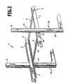
- the illustrated in the drawing storage device 1 for motor vehicles comprises a plurality of platforms 2, of which only one is shown in the drawing, while an adjacent platform 2 is indicated only by a side strut 3.
- the platforms have substantially two mutually parallel side struts 3, 4, which are stiffened by cross struts 5, 6.
- a footprint is placed, which is not shown in the drawing for clarity. There are only to suggest the footprint along the transverse struts 5, 6 wavy sections 7, which form parts of the footprint and actually extend over the entire width between the side struts 3,4.
- two vertical supports 8, 9 are arranged, on which the platform 2 is mounted vertically displaceable, for example by means of a not shown in the drawing, on the supports 8, 9 movable carriage.
- a piston-cylinder unit 10 supported on the ground is arranged next to it, the extensible piston 11 of which is connected to one of the side struts 3, 4 of the platform 2, so that upon extension of the piston from the piston-cylinder unit the platform 2 is raised.
- the piston-cylinder unit 10 is preferably supplied by supply lines, not shown in the drawing, which are laid on the floor of a building on which also the supports 8, 9 are placed.
- a height-adjustable stop 17 is arranged, which limits the lowering movement of the platform down and on which the platform touches when it has reached a rest position, for example, the lowest and / or the highest position.
- the stop 17 can be placed firmly on the support after adjusting its height, so that it supports only the platform in its lowest position. But in particular it is also possible that the stop is adjusted by a drive so in height, so that it always rests against the underside of the platform and supports it when the platform is in a rest position. In particular, the stop can be raised and lowered synchronously with the platform, so that in each position of the platform it is supported by the stop. This ensures that even with a malfunction of the lifting device or the synchronization device, the platform is still reliably supported in their respective position.
- the stop may be laterally removable from the roadway of the platform, for example, by a swiveling out, so that the platform can pass the stop when it is lowered or raised. After passing the platform, the stop can be moved back into the road, for example by swinging, and then this stop can support the platform in the assumed rest position.
Landscapes
- Engineering & Computer Science (AREA)
- Architecture (AREA)
- Structural Engineering (AREA)
- Life Sciences & Earth Sciences (AREA)
- Geology (AREA)
- Mechanical Engineering (AREA)
- Civil Engineering (AREA)
- Warehouses Or Storage Devices (AREA)
- Refuge Islands, Traffic Blockers, Or Guard Fence (AREA)
- Lock And Its Accessories (AREA)
- Air Bags (AREA)
Claims (10)
- Système de garage ou de stationnement (1) pour véhicules automobiles, comprenant au moins une plateforme (2) qui est destinée à recevoir un véhicule automobile, et est montée coulissante en hauteur sur un dispositif de guidage et peut être soulevée et abaissée au moyen d'un dispositif de levage, le système de garage comportant également une butée pour limiter le mouvement d'abaissement de la plateforme et un dispositif de synchronisation de mouvement pour produire un mouvement de levage et d'abaissement synchrone sur des côtés opposés de la plateforme (2), le dispositif de levage (10) n'agissant que sur un côté de la plateforme (2), caractérisé en ce que la butée (17) n'est agencée que sur le côté opposé de la plateforme (2).
- Système de garage selon la revendication 1, caractérisé en ce que le dispositif de synchronisation de mouvement (16) comprend un arbre de torsion (15) rotatif, qui s'étend d'un côté de la plateforme (2) à l'autre côté, et engrène, sur les deux côtés de la plateforme (2), au moyen d'un pignon denté (13, 14) respectif, avec une crémaillère ou une chaîne (12) respective agencée verticalement et en position fixe.
- Système de garage selon l'une des revendications 1 ou 2, caractérisé en ce que le dispositif de levage est un ensemble piston-cylindre (10) fonctionnant par voie hydraulique ou pneumatique.
- Système de garage selon l'une des revendications précédentes, caractérisé en ce que dispositif de guidage comprend deux montants (8, 9) agencés sur des côtés opposés de la plateforme (2), et le long desquels est guidée de manière coulissante la plateforme (2).
- Système de garage selon la revendication 4, caractérisé en ce que le dispositif de levage (10) est agencé sur l'un des montants (8).
- Système de garage selon la revendication 4 ou la revendication 5, caractérisé en ce que la butée (17) est agencée sur l'un des montants (9).
- Système de garage selon l'une des revendications précédentes, caractérisé en ce que la butée (17) est réglable.
- Système de garage selon la revendication 7, caractérisé en ce que la butée (17) est réglable en hauteur conformément à la position considérée de la plateforme (2), de sorte que la plateforme (2) repose, au moins dans chaque position de repos et de préférence dans chaque position, sur la butée (17).
- Système de garage selon la revendication 2 et selon l'une des revendications 4 à 8, caractérisé en ce que les crémaillères ou chaînes (12) du dispositif de synchronisation de mouvement (16) sont agencées sur les deux montants (8, 9).
- Système de garage selon l'une des revendications précédentes, caractérisé en ce qu'il comprend plusieurs plateformes (2) agencées côte à côte, sensiblement de même mode de construction, et en ce que les dispositifs de levage (10) de deux plateformes (2) agencées respectivement côte à côte, sont agencés sur les côtés mutuellement adjacents des plateformes (2).
Applications Claiming Priority (1)
| Application Number | Priority Date | Filing Date | Title |
|---|---|---|---|
| PCT/EP2007/002628 WO2008116479A1 (fr) | 2007-03-24 | 2007-03-24 | Système de stationnement pour véhicules automobiles |
Publications (2)
| Publication Number | Publication Date |
|---|---|
| EP2126251A1 EP2126251A1 (fr) | 2009-12-02 |
| EP2126251B1 true EP2126251B1 (fr) | 2010-09-01 |
Family
ID=38739465
Family Applications (1)
| Application Number | Title | Priority Date | Filing Date |
|---|---|---|---|
| EP07723575A Not-in-force EP2126251B1 (fr) | 2007-03-24 | 2007-03-24 | Système de stationnement pour véhicules automobiles |
Country Status (5)
| Country | Link |
|---|---|
| US (1) | US20100040443A1 (fr) |
| EP (1) | EP2126251B1 (fr) |
| AT (1) | ATE479805T1 (fr) |
| DE (1) | DE502007004973D1 (fr) |
| WO (1) | WO2008116479A1 (fr) |
Cited By (1)
| Publication number | Priority date | Publication date | Assignee | Title |
|---|---|---|---|---|
| CN113252833A (zh) * | 2021-06-08 | 2021-08-13 | 广州国标检验检测有限公司 | 一种格列吡嗪片中氯甲酸乙酯智能检测方法 |
Families Citing this family (6)
| Publication number | Priority date | Publication date | Assignee | Title |
|---|---|---|---|---|
| CN102839834A (zh) * | 2012-03-12 | 2012-12-26 | 梁嘉麟 | 修建在狭窄道路上的敞开式立体车库及其使用方法 |
| CN102720382A (zh) * | 2012-03-20 | 2012-10-10 | 周巽 | 设置在居民小区狭窄道路上的夜间空中敞开式立体车库 |
| CN103967299B (zh) * | 2013-11-15 | 2017-06-20 | 康金华 | 一种可折叠上下独立双层停车库 |
| CN108868231B (zh) * | 2018-08-16 | 2024-07-16 | 佛山职业技术学院 | 一种停车装置 |
| CN112607663B (zh) * | 2020-12-11 | 2022-07-19 | 天津天源国电电力技术有限公司 | 一种高压智能电网变压器安装施工方法 |
| CN113323464B (zh) * | 2021-05-14 | 2022-05-03 | 合肥巍华智能停车设备有限公司 | 一种智能停车升降装置 |
Family Cites Families (8)
| Publication number | Priority date | Publication date | Assignee | Title |
|---|---|---|---|---|
| US3750899A (en) * | 1971-03-18 | 1973-08-07 | Crown Parking Prod Co | Vertical-lift double-deck parking structure |
| US4086982A (en) * | 1976-11-02 | 1978-05-02 | Jack Frank Hernick | Apparatus for supporting an automobile at an elevation |
| US4167365A (en) * | 1977-08-22 | 1979-09-11 | Spiridon Constantinescu | Car parking system |
| US4209276A (en) * | 1978-06-05 | 1980-06-24 | Arnold M. Rosen | Vehicle parking apparatus |
| US4316527A (en) * | 1978-09-30 | 1982-02-23 | Kaspar Klaus | Apparatus for the parking of vehicles on mobile platforms |
| WO1994012410A1 (fr) * | 1992-11-25 | 1994-06-09 | Steven Anthony Beaumont | Elevateur pour vehicules |
| US5314285A (en) * | 1993-01-13 | 1994-05-24 | Necer International Co., Ltd. | Automatic controlled multi-level storage system |
| DE102005014282A1 (de) * | 2004-12-17 | 2006-06-29 | Klaus Multiparking Gmbh | Abstellvorrichtung für Kraftfahrzeuge |
-
2007
- 2007-03-24 EP EP07723575A patent/EP2126251B1/fr not_active Not-in-force
- 2007-03-24 AT AT07723575T patent/ATE479805T1/de active
- 2007-03-24 WO PCT/EP2007/002628 patent/WO2008116479A1/fr active Application Filing
- 2007-03-24 DE DE502007004973T patent/DE502007004973D1/de active Active
-
2009
- 2009-08-14 US US12/583,182 patent/US20100040443A1/en not_active Abandoned
Cited By (2)
| Publication number | Priority date | Publication date | Assignee | Title |
|---|---|---|---|---|
| CN113252833A (zh) * | 2021-06-08 | 2021-08-13 | 广州国标检验检测有限公司 | 一种格列吡嗪片中氯甲酸乙酯智能检测方法 |
| CN113252833B (zh) * | 2021-06-08 | 2021-11-02 | 广州国标检验检测有限公司 | 一种格列吡嗪片中氯甲酸乙酯智能检测方法 |
Also Published As
| Publication number | Publication date |
|---|---|
| ATE479805T1 (de) | 2010-09-15 |
| WO2008116479A1 (fr) | 2008-10-02 |
| EP2126251A1 (fr) | 2009-12-02 |
| US20100040443A1 (en) | 2010-02-18 |
| DE502007004973D1 (de) | 2010-10-14 |
Similar Documents
| Publication | Publication Date | Title |
|---|---|---|
| EP2126251B1 (fr) | Système de stationnement pour véhicules automobiles | |
| EP2118406B1 (fr) | Installation de parking pour véhicules automobiles et procédé pour son fonctionnement | |
| EP2150663B1 (fr) | Dispositif de rangement pour véhicules à moteur | |
| EP2719653B1 (fr) | Table élévatrice motorisée réglable en hauteur en direction verticale, p. ex. destinée à être utilisée dans le domaine de la carrosserie dans le secteur des véhicules automobiles | |
| DE4430543C2 (de) | Hubvorrichtung | |
| DE102013102464A1 (de) | Scherenhubtisch | |
| DE102004059816A1 (de) | Verleimpresse für lamellenförmige Hölzer sowie Verfahren zum Verpressen solcher Hölzer | |
| DE19543301C2 (de) | Hubvorrichtung für Sitz-, Liege- oder Abstellflächen | |
| DE2119316A1 (de) | Aufzug für Fahrzeuge | |
| DE2005446B2 (de) | Plattenbeladevorrichtung | |
| DE2165244C2 (de) | Vorrichtung zum Heben und Kippen von Kraftfahrzeugen | |
| AT400940B (de) | Maschinengestell mit begehbarer plattform | |
| EP0617945A2 (fr) | Lit, en particulier lit de malades et/ou de soins | |
| DE202007004357U1 (de) | Abstellvorrichtung für Kraftfahrzeuge | |
| DE19533887C2 (de) | Vorrichtung zum Abstellen von mehreren Fahrzeugen oder dergleichen übereinander | |
| DE102008034431B4 (de) | Batteriewagen zur Aufnahme eines Batterietrogs für ein Flurförderzeug | |
| DE2460741C3 (de) | Vorrichtung zum Ausrichten von zu besäumenden Brettern | |
| DE102004044969A1 (de) | Personenlift für eine Montagegrube, insbesondere für Kraftfahr- oder Schienenfahrzeuge | |
| DE9415656U1 (de) | Hubtisch | |
| DE102018125663B4 (de) | Lastausgleichsvorrichtung, Tisch und Arbeitstisch mit einer Lastausgleichsvorrichtung | |
| DE19849444A1 (de) | Vorrichtung zum Abstellen von Kraftfahrzeugen | |
| DE202007002069U1 (de) | Parkanlage für Kraftfahrzeuge | |
| DE202004004934U1 (de) | Geländeneignungsanpassbares Fahrgestell | |
| DE2404388C2 (de) | Vorrichtung zum Einlagern und Entnehmen schwerer zylindrischer Körper in bzw. aus Traggestellen | |
| DE1539826C (de) | Tragvorrichtung fur eine Beschickungs maschine eines Kernreaktors |
Legal Events
| Date | Code | Title | Description |
|---|---|---|---|
| PUAI | Public reference made under article 153(3) epc to a published international application that has entered the european phase |
Free format text: ORIGINAL CODE: 0009012 |
|
| 17P | Request for examination filed |
Effective date: 20090807 |
|
| AK | Designated contracting states |
Kind code of ref document: A1 Designated state(s): AT BE BG CH CY CZ DE DK EE ES FI FR GB GR HU IE IS IT LI LT LU LV MC MT NL PL PT RO SE SI SK TR |
|
| GRAP | Despatch of communication of intention to grant a patent |
Free format text: ORIGINAL CODE: EPIDOSNIGR1 |
|
| GRAC | Information related to communication of intention to grant a patent modified |
Free format text: ORIGINAL CODE: EPIDOSCIGR1 |
|
| DAX | Request for extension of the european patent (deleted) | ||
| GRAS | Grant fee paid |
Free format text: ORIGINAL CODE: EPIDOSNIGR3 |
|
| GRAA | (expected) grant |
Free format text: ORIGINAL CODE: 0009210 |
|
| AK | Designated contracting states |
Kind code of ref document: B1 Designated state(s): AT BE BG CH CY CZ DE DK EE ES FI FR GB GR HU IE IS IT LI LT LU LV MC MT NL PL PT RO SE SI SK TR |
|
| REG | Reference to a national code |
Ref country code: GB Ref legal event code: FG4D Free format text: NOT ENGLISH |
|
| REG | Reference to a national code |
Ref country code: CH Ref legal event code: NV Representative=s name: ISLER & PEDRAZZINI AG Ref country code: CH Ref legal event code: EP |
|
| REG | Reference to a national code |
Ref country code: IE Ref legal event code: FG4D Free format text: LANGUAGE OF EP DOCUMENT: GERMAN |
|
| REG | Reference to a national code |
Ref country code: NL Ref legal event code: T3 |
|
| REF | Corresponds to: |
Ref document number: 502007004973 Country of ref document: DE Date of ref document: 20101014 Kind code of ref document: P |
|
| PG25 | Lapsed in a contracting state [announced via postgrant information from national office to epo] |
Ref country code: LT Free format text: LAPSE BECAUSE OF FAILURE TO SUBMIT A TRANSLATION OF THE DESCRIPTION OR TO PAY THE FEE WITHIN THE PRESCRIBED TIME-LIMIT Effective date: 20100901 Ref country code: FI Free format text: LAPSE BECAUSE OF FAILURE TO SUBMIT A TRANSLATION OF THE DESCRIPTION OR TO PAY THE FEE WITHIN THE PRESCRIBED TIME-LIMIT Effective date: 20100901 |
|
| LTIE | Lt: invalidation of european patent or patent extension |
Effective date: 20100901 |
|
| PG25 | Lapsed in a contracting state [announced via postgrant information from national office to epo] |
Ref country code: SI Free format text: LAPSE BECAUSE OF FAILURE TO SUBMIT A TRANSLATION OF THE DESCRIPTION OR TO PAY THE FEE WITHIN THE PRESCRIBED TIME-LIMIT Effective date: 20100901 Ref country code: CY Free format text: LAPSE BECAUSE OF FAILURE TO SUBMIT A TRANSLATION OF THE DESCRIPTION OR TO PAY THE FEE WITHIN THE PRESCRIBED TIME-LIMIT Effective date: 20100901 Ref country code: PL Free format text: LAPSE BECAUSE OF FAILURE TO SUBMIT A TRANSLATION OF THE DESCRIPTION OR TO PAY THE FEE WITHIN THE PRESCRIBED TIME-LIMIT Effective date: 20100901 |
|
| REG | Reference to a national code |
Ref country code: IE Ref legal event code: FD4D |
|
| PG25 | Lapsed in a contracting state [announced via postgrant information from national office to epo] |
Ref country code: GR Free format text: LAPSE BECAUSE OF FAILURE TO SUBMIT A TRANSLATION OF THE DESCRIPTION OR TO PAY THE FEE WITHIN THE PRESCRIBED TIME-LIMIT Effective date: 20101202 Ref country code: LV Free format text: LAPSE BECAUSE OF FAILURE TO SUBMIT A TRANSLATION OF THE DESCRIPTION OR TO PAY THE FEE WITHIN THE PRESCRIBED TIME-LIMIT Effective date: 20100901 Ref country code: SE Free format text: LAPSE BECAUSE OF FAILURE TO SUBMIT A TRANSLATION OF THE DESCRIPTION OR TO PAY THE FEE WITHIN THE PRESCRIBED TIME-LIMIT Effective date: 20100901 |
|
| PG25 | Lapsed in a contracting state [announced via postgrant information from national office to epo] |
Ref country code: IE Free format text: LAPSE BECAUSE OF FAILURE TO SUBMIT A TRANSLATION OF THE DESCRIPTION OR TO PAY THE FEE WITHIN THE PRESCRIBED TIME-LIMIT Effective date: 20100901 |
|
| PG25 | Lapsed in a contracting state [announced via postgrant information from national office to epo] |
Ref country code: PT Free format text: LAPSE BECAUSE OF FAILURE TO SUBMIT A TRANSLATION OF THE DESCRIPTION OR TO PAY THE FEE WITHIN THE PRESCRIBED TIME-LIMIT Effective date: 20110103 Ref country code: EE Free format text: LAPSE BECAUSE OF FAILURE TO SUBMIT A TRANSLATION OF THE DESCRIPTION OR TO PAY THE FEE WITHIN THE PRESCRIBED TIME-LIMIT Effective date: 20100901 Ref country code: RO Free format text: LAPSE BECAUSE OF FAILURE TO SUBMIT A TRANSLATION OF THE DESCRIPTION OR TO PAY THE FEE WITHIN THE PRESCRIBED TIME-LIMIT Effective date: 20100901 Ref country code: CZ Free format text: LAPSE BECAUSE OF FAILURE TO SUBMIT A TRANSLATION OF THE DESCRIPTION OR TO PAY THE FEE WITHIN THE PRESCRIBED TIME-LIMIT Effective date: 20100901 Ref country code: IS Free format text: LAPSE BECAUSE OF FAILURE TO SUBMIT A TRANSLATION OF THE DESCRIPTION OR TO PAY THE FEE WITHIN THE PRESCRIBED TIME-LIMIT Effective date: 20110101 Ref country code: SK Free format text: LAPSE BECAUSE OF FAILURE TO SUBMIT A TRANSLATION OF THE DESCRIPTION OR TO PAY THE FEE WITHIN THE PRESCRIBED TIME-LIMIT Effective date: 20100901 |
|
| PG25 | Lapsed in a contracting state [announced via postgrant information from national office to epo] |
Ref country code: ES Free format text: LAPSE BECAUSE OF FAILURE TO SUBMIT A TRANSLATION OF THE DESCRIPTION OR TO PAY THE FEE WITHIN THE PRESCRIBED TIME-LIMIT Effective date: 20101212 |
|
| PLBE | No opposition filed within time limit |
Free format text: ORIGINAL CODE: 0009261 |
|
| STAA | Information on the status of an ep patent application or granted ep patent |
Free format text: STATUS: NO OPPOSITION FILED WITHIN TIME LIMIT |
|
| 26N | No opposition filed |
Effective date: 20110606 |
|
| PG25 | Lapsed in a contracting state [announced via postgrant information from national office to epo] |
Ref country code: DK Free format text: LAPSE BECAUSE OF FAILURE TO SUBMIT A TRANSLATION OF THE DESCRIPTION OR TO PAY THE FEE WITHIN THE PRESCRIBED TIME-LIMIT Effective date: 20100901 |
|
| BERE | Be: lapsed |
Owner name: OTTO WOHR G.M.B.H. Effective date: 20110331 |
|
| REG | Reference to a national code |
Ref country code: DE Ref legal event code: R097 Ref document number: 502007004973 Country of ref document: DE Effective date: 20110606 |
|
| PG25 | Lapsed in a contracting state [announced via postgrant information from national office to epo] |
Ref country code: MC Free format text: LAPSE BECAUSE OF NON-PAYMENT OF DUE FEES Effective date: 20110331 |
|
| PG25 | Lapsed in a contracting state [announced via postgrant information from national office to epo] |
Ref country code: BE Free format text: LAPSE BECAUSE OF NON-PAYMENT OF DUE FEES Effective date: 20110331 Ref country code: MT Free format text: LAPSE BECAUSE OF FAILURE TO SUBMIT A TRANSLATION OF THE DESCRIPTION OR TO PAY THE FEE WITHIN THE PRESCRIBED TIME-LIMIT Effective date: 20100901 |
|
| PGFP | Annual fee paid to national office [announced via postgrant information from national office to epo] |
Ref country code: IT Payment date: 20120320 Year of fee payment: 6 |
|
| PGFP | Annual fee paid to national office [announced via postgrant information from national office to epo] |
Ref country code: GB Payment date: 20130320 Year of fee payment: 7 Ref country code: CH Payment date: 20130312 Year of fee payment: 7 Ref country code: FR Payment date: 20130325 Year of fee payment: 7 |
|
| PG25 | Lapsed in a contracting state [announced via postgrant information from national office to epo] |
Ref country code: LU Free format text: LAPSE BECAUSE OF NON-PAYMENT OF DUE FEES Effective date: 20110324 |
|
| PGFP | Annual fee paid to national office [announced via postgrant information from national office to epo] |
Ref country code: NL Payment date: 20130309 Year of fee payment: 7 |
|
| PGFP | Annual fee paid to national office [announced via postgrant information from national office to epo] |
Ref country code: AT Payment date: 20130226 Year of fee payment: 7 |
|
| PGFP | Annual fee paid to national office [announced via postgrant information from national office to epo] |
Ref country code: DE Payment date: 20130424 Year of fee payment: 7 |
|
| PG25 | Lapsed in a contracting state [announced via postgrant information from national office to epo] |
Ref country code: TR Free format text: LAPSE BECAUSE OF FAILURE TO SUBMIT A TRANSLATION OF THE DESCRIPTION OR TO PAY THE FEE WITHIN THE PRESCRIBED TIME-LIMIT Effective date: 20100901 Ref country code: BG Free format text: LAPSE BECAUSE OF FAILURE TO SUBMIT A TRANSLATION OF THE DESCRIPTION OR TO PAY THE FEE WITHIN THE PRESCRIBED TIME-LIMIT Effective date: 20101201 |
|
| PG25 | Lapsed in a contracting state [announced via postgrant information from national office to epo] |
Ref country code: HU Free format text: LAPSE BECAUSE OF FAILURE TO SUBMIT A TRANSLATION OF THE DESCRIPTION OR TO PAY THE FEE WITHIN THE PRESCRIBED TIME-LIMIT Effective date: 20100901 |
|
| REG | Reference to a national code |
Ref country code: DE Ref legal event code: R119 Ref document number: 502007004973 Country of ref document: DE |
|
| REG | Reference to a national code |
Ref country code: NL Ref legal event code: V1 Effective date: 20141001 |
|
| REG | Reference to a national code |
Ref country code: CH Ref legal event code: PL |
|
| REG | Reference to a national code |
Ref country code: AT Ref legal event code: MM01 Ref document number: 479805 Country of ref document: AT Kind code of ref document: T Effective date: 20140324 |
|
| GBPC | Gb: european patent ceased through non-payment of renewal fee |
Effective date: 20140324 |
|
| REG | Reference to a national code |
Ref country code: FR Ref legal event code: ST Effective date: 20141128 |
|
| REG | Reference to a national code |
Ref country code: DE Ref legal event code: R119 Ref document number: 502007004973 Country of ref document: DE Effective date: 20141001 |
|
| PG25 | Lapsed in a contracting state [announced via postgrant information from national office to epo] |
Ref country code: LI Free format text: LAPSE BECAUSE OF NON-PAYMENT OF DUE FEES Effective date: 20140331 Ref country code: FR Free format text: LAPSE BECAUSE OF NON-PAYMENT OF DUE FEES Effective date: 20140331 Ref country code: GB Free format text: LAPSE BECAUSE OF NON-PAYMENT OF DUE FEES Effective date: 20140324 Ref country code: DE Free format text: LAPSE BECAUSE OF NON-PAYMENT OF DUE FEES Effective date: 20141001 Ref country code: CH Free format text: LAPSE BECAUSE OF NON-PAYMENT OF DUE FEES Effective date: 20140331 |
|
| PG25 | Lapsed in a contracting state [announced via postgrant information from national office to epo] |
Ref country code: NL Free format text: LAPSE BECAUSE OF NON-PAYMENT OF DUE FEES Effective date: 20141001 Ref country code: AT Free format text: LAPSE BECAUSE OF NON-PAYMENT OF DUE FEES Effective date: 20140324 |
|
| PG25 | Lapsed in a contracting state [announced via postgrant information from national office to epo] |
Ref country code: IT Free format text: LAPSE BECAUSE OF NON-PAYMENT OF DUE FEES Effective date: 20140324 |