EP2099672B1 - Chenille robotique dotée d'un bras mobile - Google Patents
Chenille robotique dotée d'un bras mobile Download PDFInfo
- Publication number
- EP2099672B1 EP2099672B1 EP07870880A EP07870880A EP2099672B1 EP 2099672 B1 EP2099672 B1 EP 2099672B1 EP 07870880 A EP07870880 A EP 07870880A EP 07870880 A EP07870880 A EP 07870880A EP 2099672 B1 EP2099672 B1 EP 2099672B1
- Authority
- EP
- European Patent Office
- Prior art keywords
- frame
- robotic crawler
- arm
- tracked robotic
- continuous track
- Prior art date
- Legal status (The legal status is an assumption and is not a legal conclusion. Google has not performed a legal analysis and makes no representation as to the accuracy of the status listed.)
- Active
Links
- 230000033001 locomotion Effects 0.000 claims abstract description 31
- 238000000034 method Methods 0.000 claims description 13
- 238000005452 bending Methods 0.000 claims description 6
- 230000008878 coupling Effects 0.000 claims 1
- 238000010168 coupling process Methods 0.000 claims 1
- 238000005859 coupling reaction Methods 0.000 claims 1
- 230000009194 climbing Effects 0.000 description 10
- 238000012986 modification Methods 0.000 description 3
- 230000004048 modification Effects 0.000 description 3
- WYTGDNHDOZPMIW-RCBQFDQVSA-N alstonine Natural products C1=CC2=C3C=CC=CC3=NC2=C2N1C[C@H]1[C@H](C)OC=C(C(=O)OC)[C@H]1C2 WYTGDNHDOZPMIW-RCBQFDQVSA-N 0.000 description 2
- 238000010586 diagram Methods 0.000 description 2
- 230000006978 adaptation Effects 0.000 description 1
- 230000004075 alteration Effects 0.000 description 1
- 230000007812 deficiency Effects 0.000 description 1
- 230000002708 enhancing effect Effects 0.000 description 1
- 231100001261 hazardous Toxicity 0.000 description 1
- 230000007246 mechanism Effects 0.000 description 1
- 239000000126 substance Substances 0.000 description 1
- 238000004804 winding Methods 0.000 description 1
Images


Classifications
-
- B—PERFORMING OPERATIONS; TRANSPORTING
- B62—LAND VEHICLES FOR TRAVELLING OTHERWISE THAN ON RAILS
- B62D—MOTOR VEHICLES; TRAILERS
- B62D55/00—Endless track vehicles
- B62D55/06—Endless track vehicles with tracks without ground wheels
- B62D55/065—Multi-track vehicles, i.e. more than two tracks
- B62D55/0655—Articulated endless track vehicles
-
- B—PERFORMING OPERATIONS; TRANSPORTING
- B62—LAND VEHICLES FOR TRAVELLING OTHERWISE THAN ON RAILS
- B62D—MOTOR VEHICLES; TRAILERS
- B62D55/00—Endless track vehicles
- B62D55/06—Endless track vehicles with tracks without ground wheels
- B62D55/075—Tracked vehicles for ascending or descending stairs, steep slopes or vertical surfaces
-
- B—PERFORMING OPERATIONS; TRANSPORTING
- B62—LAND VEHICLES FOR TRAVELLING OTHERWISE THAN ON RAILS
- B62D—MOTOR VEHICLES; TRAILERS
- B62D57/00—Vehicles characterised by having other propulsion or other ground- engaging means than wheels or endless track, alone or in addition to wheels or endless track
- B62D57/02—Vehicles characterised by having other propulsion or other ground- engaging means than wheels or endless track, alone or in addition to wheels or endless track with ground-engaging propulsion means, e.g. walking members
- B62D57/024—Vehicles characterised by having other propulsion or other ground- engaging means than wheels or endless track, alone or in addition to wheels or endless track with ground-engaging propulsion means, e.g. walking members specially adapted for moving on inclined or vertical surfaces
-
- B—PERFORMING OPERATIONS; TRANSPORTING
- B62—LAND VEHICLES FOR TRAVELLING OTHERWISE THAN ON RAILS
- B62D—MOTOR VEHICLES; TRAILERS
- B62D57/00—Vehicles characterised by having other propulsion or other ground- engaging means than wheels or endless track, alone or in addition to wheels or endless track
- B62D57/02—Vehicles characterised by having other propulsion or other ground- engaging means than wheels or endless track, alone or in addition to wheels or endless track with ground-engaging propulsion means, e.g. walking members
- B62D57/028—Vehicles characterised by having other propulsion or other ground- engaging means than wheels or endless track, alone or in addition to wheels or endless track with ground-engaging propulsion means, e.g. walking members having wheels and mechanical legs
Definitions
- the present invention relates to small, unmanned ground robotic vehicles. More particularly, the present invention relates to a tracked robotic crawler having at least one moveable arm.
- Robotics is an active area of research, and many different types of robotic vehicles have been developed for various tasks.
- unmanned aerial vehicles have been quite successful in military aerial reconnaissance.
- Less success has been achieved with unmanned ground vehicles, however, in part because the ground environment is significantly more difficult to traverse than the airborne environment.
- Unmanned ground vehicles face many challenges when attempting mobility.
- Terrain can vary widely, including for example, loose and shifting materials, obstacles, vegetation, limited width or height openings, steps, and the like.
- a vehicle optimized for operation in one environment may perform poorly in other environments.
- Legged robots can be agile, but use complex control mechanisms to move and achieve stability.
- Wheeled vehicles can provide high mobility, but provide limited traction and require width in order to achieve stability.
- Tracked vehicles are known in the art and have traditionally been configured in a tank-like configuration. While tracked vehicles can provide a high degree of stability in some environments, tracked vehicles typically provide limited maneuverability with very small vehicles. Furthermore, known tracked vehicles are unable to accommodate a wide variety of obstacles, particularly when the terrain is narrow and the paths are tortuous and winding.
- the present invention includes a robotic crawler which helps to overcome problems and deficiencies inherent in the prior art.
- the robotic crawler includes at least one frame unit which has a continuous track rotatably coupled to the frame unit with at least one surface of the continuous track being exposed to enable engagement with a surface for propulsion of the frame unit.
- Disposed on the frame unit is at least one arm. The arm is moveable relative to the frame unit, and can be stowed within the perimeter of the continuous track.
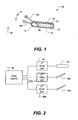
- FIG. 1 illustrates the tracked robotic crawler 10 as including a frame unit 12 having a continuous track 14. More than one continuous track can be included in the frame, if desired. At least one surface 16 of the continuous track is exposed to enable engagement with a surface for propulsion of the frame unit. Attached to the frame unit on opposite sides are at least two articulated arms 18a, 18b. The articulated arms are moveable independently of each other in at least one dimension. For example, the articulated arms can mounted on a common axis 20, providing rotational movement in direction 22. Each articulated arm is thus moveable in a plane parallel to the side of the frame unit.
- the articulated arm is moveable in a plane perpendicular to an axis of rotation of the continuous track of the frame unit.
- the frame unit can be substantially enclosed inside a perimeter defined by an inner surface of the continuous track, helping to maintain a small profile. It will be understood, of course, that portions of the frame may extend laterally to connect to joints or other features of the tracked robotic crawler. Various other arrangements of articulated arms can be used as described further below.
- the articulated arms can be used to aid in propulsion of the tracked robotic crawler 10.
- the articulated arms can be rotated to a position extending past the front end of the frame unit, for example, to help lift the front end of the frame unit over an obstacle.
- the articulated arms can also be rotated into a stowed position (for example, as shown by dotted lines 18') where they are substantially contained within the perimeter defined by an inner surface 21 of the continuous track.
- the tracked robotic crawler 10 can include a track drive unit 24 coupled to the continuous track 14, and one or more arm drive units 26a, 26b coupled respectively to the articulated arms 18a, 18b.
- the track drive unit can control motion of the continuous track, for example, controlling the direction (forward or reverse) and speed of movement.
- the arm drive units can control motion of the articulated arms. Propulsion of the tracked robotic crawler can include coordinated movement of the continuous track and the articulated arms as will be discussed in further detail below.
- a tracked robotic crawler can also include multiple frame units, as illustrated in FIG. 3 in accordance with another embodiment of the present invention.
- a tracked robotic crawler 30 includes a plurality of frame units 12a, 12b, 12c coupled in a series configuration in a train-like arrangement. Each frame unit includes a continuous track 14a, 14b, 14c, as described above.
- the frame units are coupled through joints 32.
- the joints can be passive or actuated joints. Actuated joints are discussed in further detail below.
- One or more of the frames 14 can include at least one articulated arm 18.
- a single armed frame unit can have an articulated arm, with other frames being armless.
- each frame unit can have one or more arms.
- the first and last frame unit within the train can have arms, and intermediate units can be armless.
- Articulated arms can be coupled to the frames at various locations, including for example, near the front, near the back, or near the center.
- an articulated arm is located near one end (e.g., the front) of a frame unit, and the joint 32 is connected near the other end (e.g., the rear) of the frame unit.
- the tracked robotic crawler 40 includes a first frame unit 12a and a second frame unit 12b, the frame units having continuous tracks 14a, 14b as described above. Articulated arms 18a, 18b, 18c, 18d are disposed in opposing pairs on each frame unit.
- the first frame unit and second frame unit are coupled by an actuated linkage 34.
- the actuated linkage provides controllable bending about at least one axis.
- the actuated linkage can include joints providing bending about seven different axes as shown here.
- the tracked robotic crawler 40 includes track drive units 24a, 24b coupled respectively to the continuous tracks 14a, 14b. Also included are arm drive units 26a, 26b. Each arm drive unit 26a, 26b controls a pair of arms, 18a, 18b and 18c, 18d, respectively, although alternately separate drive units can also be provided for each arm.
- a drive control system 36 is coupled to the drive units to coordinate movement of the continuous tracks and arms to provide propulsion of the tracked robotic crawler.
- the actuated linkage 34 can also be coupled to the drive control system to coordinate movement and pose of the tracked robotic crawler.
- a first pose will be referred to herein as the "train" configuration where the first frame 12a and second frame 12b are positioned in line as illustrated in FIG. 6 .
- the frames can be, but need not be, aligned in a line.
- the train configuration provides a small profile, allowing narrow passages and openings (e.g., tunnel 60) to be passed through.
- the tracked robotic crawler can be moved in a forward and reverse direction by driving the continuous tracks 14a, 14b so they move in the same relative direction.
- one continuous track can be driven and the other continuous track left in a passive mode.
- the arms 18 can be deployed to extend beyond the ends of the frames to contact the surface and provide additional length to the tracked robotic crawler 40, for example, as illustrated in FIG. 6 .
- the added length also provides additional stability. This enhances the ability of the tracked robotic crawler to cross gaps and holes (e.g., canyon 62).
- the actuated linkage arm 34 can be operated to create an angle between the first frame 12a and the second frame 12b.
- one or more of the arms 18 can be extended to dig into the surface to provide an off-center point (or points) of resistance which the frame(s) torques around as drive is applied to the continuous tracks 14.
- operation of the actuated linkage arm, arms, and track can be coordinated to execute a turn.
- a second pose will be referred to herein as the "tank" configuration, where the first frame 12a and second frame 12b are positioned side by side as illustrated in FIG. 7 .
- the frames can be, but need not be, parallel.
- the tank configuration provides lateral stability to the tracked robotic crawler 40, for example when traversing a steep slope.
- the tracked robotic crawler can be moved in a forward and reserve direction by driving the continuous tracks 14a, 14b in the same relative direction, and turned by driving the continuous tracks in opposite directions.
- moving the tracked robotic crawler in the tank-like configuration can involve applying different drive speeds (including opposite directions) to the continuous tracks. Note that, relative to the train configuration, the direction sense of one of the continuous tracks is reversed.
- the arms 18 can be extended to contact the surface to provide additional stability and/or traction.
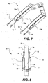
- the tracked robotic crawler can also be configured for climbing the exterior of structure in an outside-climbing configuration. As illustrated in FIG. 8 , the tracked robotic crawler 40 is wrapped around the structure 70 so that exposed portions 72, 74 of the continuous tracks 14 face toward each other and contact opposite outer surfaces 76, 78 of the structure.
- the arms 18 can be extended past the ends of the frames 12 to contact the outer surface of the structure to provide additional stability and/or traction. For example, the arms can help to maintain the tracked robotic crawler centered on the structure.
- the continuous tracks can be driven to move the tracked robotic crawler up and down the structure.
- Many different structural geometries including for example a pole, can be climbed in this outside-climbing configuration.
- the tracked robotic crawler can also be configured for climbing the interior of a structure.
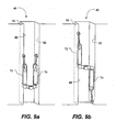
- FIGS. 9(a) and 9(b) illustrate two different inside-climbing configurations.
- the tracked robotic crawler 40 is configured so that exposed portions 72, 74 of the continuous tracks face away from each other and are in contact with opposite inner surfaces 80, 82 of the structure 70.
- the arms can be extended past the ends of the frames to contact the inner surface of the structure.
- the arms can be positioned to contact the same inner surface as their corresponding continuous track, as shown in FIGS. 9(a) and 9(b) .
- arms can be positioned to contact the opposite inner surface, as shown in the alternate pose of FIG. 10(a) .
- FIG. 9(a) and 9(b) illustrate two different inside-climbing configurations.
- the tracked robotic crawler 40 is configured so that exposed portions 72, 74 of the continuous tracks face away from each other and are in contact with opposite inner surfaces 80, 82 of the structure 70.
- the arms can be extended past the ends
- the continuous tracks can face the same direction in contact with one inner surface 80 and the arms can contact the opposite inner surface 82.
- the arms can help to increase force between the continuous track and the inner surface, increasing traction of the continuous track.
- the inside-climbing configurations can be useful for climbing pipes, chimneys, wall interiors, and the like.
- FIGS. 11(a)-11(i) provide a side view sequence of illustrations illustrating a tracked robotic crawler 40 climbing a set of stairs 86.
- the tracked robotic crawler assumes a train configuration, if it is not already in that pose, as shown in FIG. 11(a) .
- the tracked robotic crawler then rotates the arms into a position, where the forward arms extend in front of the first frame, as shown in FIG. 11(b) .
- the forward arms are then rotated further, to lift the front of the first frame to clear the first stair, as shown in FIG. 11(c) .
- the rear arms can be rotated to contact the surface behind the tracked robotic crawler to provide additional stability and/or traction.
- the tracks can then be driven forward to move the tracked robotic crawler forward on the first stair, as shown in FIG. 11(d) .
- the rear arms can also be used to help lift the second frame, as shown in FIGS. 11(e) -11(g) .
- the arms are rotated, with the distal ends of the arms rotating in the direction of travel while above the frame unit, and rotating opposite the direction of travel while below the frame unit. This motion helps the arms to clear the obstacle, gain traction, and lift the frame unit over the obstacle. Accordingly, it is helpful if the arm drive units have sufficient torque to lift the weight of a frame unit.
- the actuated linkage 34 can provide sufficient torque to lift the frame of the first frame unit, while supported by the second frame unit. It will be appreciated that similar motions as used for climbing a set of stairs can be used for the tracked robotic crawler to enter a hole in a wall. Various other combinations of articulated movement can prove helpful, depending on the dimensions of the stairs (or other obstacles) being navigated. Additional movement modes which can be employed in embodiments of the present invention are described in the above mentioned application entitled "Serpentine Robotic Crawler".
- FIG. 12 illustrates a tracked robotic crawler 50 in accordance with another embodiment of the present invention.
- the tracked robotic crawler includes frames 12a, 12b, each having a track 14a, 14b. Coupled to the frames are jointed arms having a lower segment 52a, 52b and an upper segment 54a, 54b, connected together by joint 56a, 56b.
- Each jointed arm includes a camera 60a, 60b. Affixed to the distal end of each arm is a serrated knife edge 62a, 62b.
- the jointed arms can be used for multiple purposes.
- One purpose is support of the cameras 60a, 60b.
- the lower segments 52a, 52b can be rotated to raise or lower the camera, (e.g., to increase height to provide a better view or to reduce height to provide a lower profile).
- the upper segments 54a, 52b can be rotated to assist in propulsion, for example, as discussed above.
- the serrated knife edge 62a, 62b can help to provide traction, for example, when climbing stairs as discussed above.
- the cameras can be used to assist in navigation.
- a front camera 60a can be used primarily for scanning the environment, and a rear camera 60b can be used for observing the pose of the tracked robotic crawler for control purposes.
- various other tools can be affixed to the end of the arms, including for example lights, clamps, grippers, manipulators, cutters, drills, material samplers, sensors, etc.
- Various sensors including for example, radar, lidar, temperature sensors, chemical sensors, force sensors, motion detectors, microphones, antennas, and the like can be used.
- arms can be used which provide movement in two degrees of freedom.
- a first degree of freedom can be rotational movement in a plane tangent to the point of attachment to the frame, for example, as described above.
- a second degree of freedom can be lateral movement perpendicular to the plane.
- an arm having joints or a structure with controllable compliance can be used to provide lateral movement.
- Controllable compliance can be obtained by providing a spring bias on the arms, where the spring constant can be varied during operation by an actuator.
- the arms can be deflected inwardly and extended in front of the tracked robotic crawler to form a pointed arrangement.
- This pose can assist the tracked robotic crawler in passing through obstacles, such as dense vegetation.
- the arms can be deflected inward toward each other to improve traction, for example, when grabbing onto a convex outside surface in a outside-climbing configuration.
- the arms can also be deflected outward, for example, when providing traction on a concave curved interior surface in an inside-climbing configuration.
- the arms can be deflected outward to form outriggers, providing additional stability to the tracked robotic crawler.
- tracked robotic crawlers in accordance with embodiments of the present invention can be deployed in a variety of applications and environments.
- applications can include search and rescue, military operations, and industrial operations.
- the tracked robotic crawler can help to avoid the need to expose humans to hazardous environments, such as unstable buildings, military conflict situations, and chemically, biologically, or nuclear contaminated environments.
- the configurational flexibility of the tracked robotic crawler can provide multiple movement modes. For example, movement in a tank-like configuration can provide high stability. Movement in a train-like configuration can provide access through narrow passages or pipes and allow bridging of gaps. Climbing the outside of structures (e.g., a pole) and climbing the inside of structures (e.g. a chimney) are also possible. Climbing stairs has also been illustrated.
Landscapes
- Engineering & Computer Science (AREA)
- Chemical & Material Sciences (AREA)
- Combustion & Propulsion (AREA)
- Transportation (AREA)
- Mechanical Engineering (AREA)
- Manipulator (AREA)
Claims (20)
- Une chenille robotique se composant de ce qui suit :plusieurs unités cadres (12), chaque unité cadre étant munie d'une chenille continue (14) couplée par rotation à l'unité cadre (12), au moins une surface de la chenille continue étant exposée afin de permettre l'engagement avec une surface pour la propulsion de l'unité cadre ;au moins une liaison de commande (32, 34) couplant les unités cadres selon une configuration en série, la liaison de commande ayant au moins une articulation de commande configurée pour assurer l'inclinaison réglable sur au moins un axe ; et se caractérisant par ce qui suit :au moins un bras indépendamment mobile (18a, 18b) placé sur une des différentes unités cadres de façon à former une unité cadre à bras, le bras étant mobile dans au moins une dimension pour parvenir à une position où le bras est en grande partie contenu dans un périmètre défini par une surface intérieure de la chenille continue correspondante.
- La chenille robotique de la revendication 1, dans laquelle chacune des unités cadres est en grande partie contenue dans un périmètre défini par une surface intérieure de sa chenille continue correspondante.
- La chenille robotique de la revendication 1 , dans laquelle l'unité cadre à bras se compose de ce qui suit :une première unité d'entraînement couplée à la chenille continueune deuxième unité d'entraînement couplée au ou aux bras ; etun système de commande d'entraînement couplé aux première et deuxième unités d'entraînement et configuré pour coordonner le mouvement de la chenille continue et du ou des bras pour assurer la propulsion de la chenille robotique.
- La chenille robotique de la revendication 3, dans laquelle la ou les liaisons de commande sont raccordées au système de commande d'entraînement pour coordonner le mouvement et la position de la chenille robotique.
- La chenille robotique de la revendication 1, dans laquelle la ou les liaisons de commande possèdent un couple suffisant pour permettre le levage d'au moins une des unités cadres pendant qu'elles sont soutenues par au moins une unité cadre restante.
- La chenille robotique de la revendication 1, dans laquelle le ou les bras peuvent tourner sur un point de fixation à l'unité cadre à bras.
- La chenille robotique de la revendication 1, dans laquelle le ou les bras sont mobiles sur un plan en deux dimensions pour l'essentiel perpendiculaire à un axe de rotation de la chenille continue de l'unité cadre à bras.
- La chenille robotique de la revendication 1, dans laquelle le ou les bras sont raccordés à une unité d'entraînement ayant un couple suffisant pour permettre le levage de l'unité cadre à bras.
- Une chenille robotique se composant de ce qui suit :une unité cadre (12), l'unité cadre ayant uniquement une seule chenille continue (14) couplée de manière rotative au cadre avec au moins une surface de la chenille continue exposée afin de permettre l'engagement avec une surface pour la propulsion de l'unité cadre ; et se caractérisant par ce qui suit :au moins deux bras articulés (18a, 18b) disposés sur des côtés opposés de l'unité cadre, les bras articulés étant mobiles indépendamment l'un de l'autre dans au moins une dimension pour atteindre une position dans laquelle chaque bras est en grande partie contenu dans un périmètre défini par une surface intérieure de la chenille continue.
- Un procédé d'utilisation d'une chenille robotique sur une surface, se composant des étapes suivantes :(a) se procurer un premier cadre (12a) et un deuxième cadre (1 2b), chaque cadre ayant une chenille continue (14) avec une zone exposée pour l'engagement avec la surface, dans lequel au moins une chenille continue est couplée à une source d'entraînement pour assurer la rotation de la chenille continue ; se caractérisant par ce qui suit :(b) se procurer au moins deux bras articulés (18a ; 18b), un bras étant fixé à chacun des premier et deuxième cadres, les bras étant indépendamment mobiles dans au moins une dimension l'un par rapport à l'autre et par rapport à leurs cadres correspondants, chaque bras articulé pouvant être amené dans une position où le bas est pour l'essentiel contenu dans un périmètre défini par une surface intérieure de la chenille continue correspondante ;(c) se procurer un bras de liaison de commande à plusieurs degrés de liberté couplé entre le premier cadre et le deuxième cadre ; et(d) coordonner la rotation de la chenille continue, le mouvement des bras articulés et l'actionnement du bras de liaison à plusieurs degrés de liberté afin de contrôler la position et le mouvement de la chenille robotique sur la surface.
- Le procédé de la revendication 10, dans lequel l'étape (d) suppose de positionner le premier cadre et le deuxième cadre dans une configuration du type réservoir où le premier cadre et le deuxième cadre sont côte à côte et en grande partie parallèles.
- Le procédé de la revendication 11, dans lequel l'étape (d) suppose de positionner les bras articulés de façon à ce qu'ils dépassent dans la même direction des extrémités du premier cadre et du deuxième cadre pour entrer en contact avec la surface, ce qui confère une stabilité et/ou une traction supplémentaire à la chenille robotique.
- Le procédé de la revendication 10 dans lequel l'étape (d) suppose de positionner le premier cadre et le deuxième cadre dans une configuration du type train où le premier cadre et le deuxième cadre sont alignés de bout en bout.
- Le procédé de la revendication 13 dans lequel l'étape (d) suppose de positionner les bras articulés de façon à ce qu'ils dépassent des extrémités distales du premier cadre et du deuxième cadre pour entrer en contact avec la surface, ce qui confère une stabilité et/ou une traction supplémentaire à la chenille robotique.
- Le procédé de la revendication 10 dans lequel l'étape (d) suppose de positionner le premier cadre et le deuxième cadre dans une configuration d'escalade extérieure où le premier cadre et le deuxième cadre sont positionnés avec les parties exposées des chenilles continues se faisant face et en contact avec les surfaces extérieures opposées d'une structure à escalader.
- Le procédé de la revendication 15 dans lequel l'étape (d) suppose de positionner les bras articulés de façon à ce qu'ils dépassent des extrémités du premier cadre et du deuxième cadre pour entrer en contact avec la surface extérieure de la structure, ce qui confère une stabilité et/ou une traction supplémentaire à la chenille robotique.
- Le procédé de la revendication 10 dans lequel l'étape (d) suppose de positionner le premier cadre et le deuxième cadre dans une configuration d'escalade intérieure où le premier cadre et le deuxième cadre sont positionnés avec les parties exposées des chevilles continues orientées dans des directions opposées et en contact avec les surfaces intérieures opposées d'une structure à escalader.
- Le procédé de la revendication 17 dans lequel l'étape (d) suppose de positionner le bras articulé de chaque unité cadre de façon à entrer en contact avec la même surface intérieure de la structure que la partie exposée correspondante de la chenille continue, ce qui confère une stabilité et/ou une traction supplémentaire a la chenille robotique.
- Le procédé de la revendication 17 dans lequel l'étape (d) suppose de positionner le bras articulé de chaque unité cadre de façon à entrer en contact avec la surface intérieure de la structure opposée à la partie exposée correspondante de la chenille continue, ce qui confère une stabilité et/ou une traction supplémentaire à la chenille robotique.
- Le procédé de la revendication 11 dans lequel l'étape (d) suppose de positionner les bras articulés de façon à ce qu'ils dépassent vers l'avant de l'extrémité du premier ou du deuxième cadre ; et de faire dévier les bras articulés vers l'intérieur de façon à former une configuration pointue.
Priority Applications (1)
| Application Number | Priority Date | Filing Date | Title |
|---|---|---|---|
| EP11176735.6A EP2476604B1 (fr) | 2006-11-13 | 2007-11-13 | Chenille robotisée dotée d'un bras mobile |
Applications Claiming Priority (2)
| Application Number | Priority Date | Filing Date | Title |
|---|---|---|---|
| US85891506P | 2006-11-13 | 2006-11-13 | |
| PCT/US2007/023870 WO2008076193A2 (fr) | 2006-11-13 | 2007-11-13 | Chenille robotique dotée d'un bras mobile |
Publications (2)
| Publication Number | Publication Date |
|---|---|
| EP2099672A2 EP2099672A2 (fr) | 2009-09-16 |
| EP2099672B1 true EP2099672B1 (fr) | 2011-08-31 |
Family
ID=39494668
Family Applications (2)
| Application Number | Title | Priority Date | Filing Date |
|---|---|---|---|
| EP11176735.6A Not-in-force EP2476604B1 (fr) | 2006-11-13 | 2007-11-13 | Chenille robotisée dotée d'un bras mobile |
| EP07870880A Active EP2099672B1 (fr) | 2006-11-13 | 2007-11-13 | Chenille robotique dotée d'un bras mobile |
Family Applications Before (1)
| Application Number | Title | Priority Date | Filing Date |
|---|---|---|---|
| EP11176735.6A Not-in-force EP2476604B1 (fr) | 2006-11-13 | 2007-11-13 | Chenille robotisée dotée d'un bras mobile |
Country Status (7)
| Country | Link |
|---|---|
| US (1) | US8185241B2 (fr) |
| EP (2) | EP2476604B1 (fr) |
| JP (1) | JP5411702B2 (fr) |
| CN (1) | CN101583530B (fr) |
| AT (1) | ATE522431T1 (fr) |
| IL (1) | IL198711A (fr) |
| WO (1) | WO2008076193A2 (fr) |
Cited By (1)
| Publication number | Priority date | Publication date | Assignee | Title |
|---|---|---|---|---|
| US11584458B2 (en) * | 2018-11-29 | 2023-02-21 | Saudi Arabian Oil Company | Inspection method using a perching UAV with a releasable crawler |
Families Citing this family (76)
| Publication number | Priority date | Publication date | Assignee | Title |
|---|---|---|---|---|
| WO2008073203A2 (fr) | 2006-11-13 | 2008-06-19 | Raytheon Sarcos Llc | Ensemble chenille conformable pour engin robotique a chenilles |
| EP2086821B1 (fr) | 2006-11-13 | 2010-07-14 | Raytheon Sarcos LLC | Chenille sans fin polyvalente pour robots mobiles legers |
| US8002716B2 (en) | 2007-05-07 | 2011-08-23 | Raytheon Company | Method for manufacturing a complex structure |
| CN101784435B (zh) | 2007-07-10 | 2013-08-28 | 雷神萨科斯公司 | 模块化机器人履带车 |
| US10427290B2 (en) | 2017-07-18 | 2019-10-01 | General Electric Company | Crawler robot for in situ gap inspection |
| FR2929228B1 (fr) * | 2008-03-28 | 2010-06-18 | Thales Sa | Robot grimpeur de poteau. |
| US7954575B1 (en) * | 2008-09-10 | 2011-06-07 | Bloxsom Joel O | Leader string pull-through machine |
| US8525124B2 (en) | 2008-11-03 | 2013-09-03 | Redzone Robotics, Inc. | Device for pipe inspection and method of using same |
| US8392036B2 (en) | 2009-01-08 | 2013-03-05 | Raytheon Company | Point and go navigation system and method |
| WO2010144813A1 (fr) * | 2009-06-11 | 2010-12-16 | Raytheon Sarcos, Llc | Procédé et système de déploiement d'un réseau de surveillance |
| KR101208919B1 (ko) * | 2010-03-25 | 2012-12-06 | 주식회사 유진로봇 | 레이크 휠이 장착된 구동암 및 이를 구비한 이동 로봇 |
| WO2012044663A1 (fr) * | 2010-09-30 | 2012-04-05 | Schlee Keith L | Robot mobile à unités multiples |
| US9522595B2 (en) | 2011-01-27 | 2016-12-20 | Irobot Defense Holdings, Inc. | Small unmanned ground vehicle |
| US9346499B2 (en) | 2011-01-27 | 2016-05-24 | Irobot Corporation | Resilient wheel assemblies |
| US20120205168A1 (en) * | 2011-02-11 | 2012-08-16 | Christopher Ryan Flynn | Robot reconfigurable for insertion through a narrow opening |
| US9056746B2 (en) * | 2011-02-11 | 2015-06-16 | University Of Regina | Adaptable vehicle |
| CN102267503B (zh) * | 2011-05-06 | 2012-07-25 | 北京航空航天大学 | 一种由单体抛掷机器人组合而成的小型组合机器人 |
| JP5542092B2 (ja) * | 2011-05-12 | 2014-07-09 | 学校法人千葉工業大学 | 無人走行用移動体 |
| US9004200B2 (en) * | 2011-09-09 | 2015-04-14 | Pinhas Ben-Tzvi | Mobile robot with hybrid traction and mobility mechanism |
| US8574021B2 (en) | 2011-09-23 | 2013-11-05 | Mattel, Inc. | Foldable toy vehicles |
| JP2013113597A (ja) * | 2011-11-25 | 2013-06-10 | Hitachi-Ge Nuclear Energy Ltd | 調査ビークル、容器内の調査装置及び画像の処理方法 |
| US9248875B2 (en) | 2012-04-17 | 2016-02-02 | Robo-team Ltd. | Driving flipper with robotic arm |
| US8393422B1 (en) | 2012-05-25 | 2013-03-12 | Raytheon Company | Serpentine robotic crawler |
| US20140031977A1 (en) * | 2012-07-27 | 2014-01-30 | Engineering Services Inc. | Modular mobile robot |
| DE102012109040B4 (de) * | 2012-09-25 | 2014-12-11 | BIBA - Bremer Institut für Produktion und Logistik GmbH | Klettervorrichtung und Verfahren zum Ausführen von Tätigkeiten an gestapelten Gegenständen |
| CN102887187A (zh) * | 2012-10-23 | 2013-01-23 | 四川省电力公司西昌电业局 | 一种电磁式智能攀爬机器人 |
| US9031698B2 (en) | 2012-10-31 | 2015-05-12 | Sarcos Lc | Serpentine robotic crawler |
| US9409292B2 (en) * | 2013-09-13 | 2016-08-09 | Sarcos Lc | Serpentine robotic crawler for performing dexterous operations |
| US9566711B2 (en) | 2014-03-04 | 2017-02-14 | Sarcos Lc | Coordinated robotic control |
| CN104002880B (zh) * | 2014-06-03 | 2016-03-23 | 东南大学 | 一种带有导臂的履带式移动机器人自主上下楼梯控制方法 |
| JP2014238403A (ja) * | 2014-07-07 | 2014-12-18 | 日立Geニュークリア・エナジー株式会社 | 調査ビークル、容器内の調査装置及び画像の処理方法 |
| US9096281B1 (en) * | 2014-07-30 | 2015-08-04 | Engineering Services Inc. | Dual mode mobile robot |
| US9561829B1 (en) * | 2014-09-03 | 2017-02-07 | X Development Llc | Robotic leg with multiple robotic feet |
| CN104647341B (zh) * | 2015-02-28 | 2016-04-06 | 东北大学 | 一种越障式无缆遥控排险侦查机器人 |
| RU2603816C1 (ru) * | 2015-06-24 | 2016-11-27 | Федеральное государственное бюджетное образовательное учреждение высшего профессионального образования "Государственный университет - учебно-научно-производственный комплекс" (ФГБОУ ВПО "Госуниверситет-УНПК") | Транспортное средство |
| US10071303B2 (en) | 2015-08-26 | 2018-09-11 | Malibu Innovations, LLC | Mobilized cooler device with fork hanger assembly |
| US9637186B1 (en) | 2015-12-03 | 2017-05-02 | Engineering Services Inc. | Dual mode vehicle |
| GB2548917B (en) | 2016-04-01 | 2020-08-05 | Provost Fellows Found Scholars & Other Members Board College Holy & Und | Obstacle crossing robot |
| US10807659B2 (en) | 2016-05-27 | 2020-10-20 | Joseph L. Pikulski | Motorized platforms |
| JP6715462B2 (ja) * | 2016-06-02 | 2020-07-01 | パナソニックIpマネジメント株式会社 | 移動ロボット |
| US10131057B2 (en) * | 2016-09-20 | 2018-11-20 | Saudi Arabian Oil Company | Attachment mechanisms for stabilzation of subsea vehicles |
| WO2018094368A1 (fr) * | 2016-11-21 | 2018-05-24 | Schroit Sam | Système pour l'amélioration de l'efficacité opérationnelle et de performance de tracteurs à câble |
| CN108340364B (zh) * | 2017-01-24 | 2020-09-15 | 南京原觉信息科技有限公司 | 爬行机器装置与其部署方法 |
| WO2018154424A1 (fr) | 2017-02-21 | 2018-08-30 | Induna Robotics (Pty) Ltd | Agencement de membre robotisé et robot associé |
| US10596713B2 (en) | 2017-07-18 | 2020-03-24 | General Electric Company | Actuated sensor module and method for in situ gap inspection robots |
| US10427734B2 (en) * | 2017-07-18 | 2019-10-01 | General Electric Company | Omnidirectional traction module for a robot |
| US10603802B2 (en) | 2017-07-18 | 2020-03-31 | General Electric Company | End region inspection module and method for in situ gap inspection robot system |
| US10434641B2 (en) | 2017-07-18 | 2019-10-08 | General Electric Company | In situ gap inspection robot system and method |
| CN107521576B (zh) * | 2017-08-24 | 2023-09-05 | 广州南洋理工职业学院 | 一种可地面行走及爬楼梯机器人 |
| EP3684557B1 (fr) | 2017-09-19 | 2022-09-21 | Arix Technologies, Inc. | Appareil et procédés de traversée de tube |
| CN107972755A (zh) * | 2017-12-27 | 2018-05-01 | 同方威视技术股份有限公司 | 集装箱爬壁机器人 |
| CN108188467B (zh) * | 2018-03-19 | 2024-04-09 | 江苏科技大学 | 一种用于波纹管切割的自走式装置 |
| US11247737B2 (en) * | 2018-04-23 | 2022-02-15 | Eagle Technology, Llc | UGV with adaptive stabilizer |
| US20200101804A1 (en) * | 2018-09-28 | 2020-04-02 | Beijing Jingdong Shangke Information Technology Co., Ltd. | Connector for connecting trailers in mobile robotic device and method of controlling the same |
| CN109533051B (zh) * | 2018-11-29 | 2020-09-18 | 北京理工大学 | 一种具有可折叠摆臂的翻转式爬楼梯机器人 |
| CN109557173B (zh) * | 2019-01-17 | 2023-12-22 | 中国石油大学(北京) | 无损检测装置 |
| CN109911046B (zh) * | 2019-03-12 | 2023-12-15 | 无锡金诚工程技术服务有限公司 | 悬浮履带式爬索机器人 |
| CN109849018A (zh) * | 2019-04-04 | 2019-06-07 | 华夏天信(北京)智能低碳技术研究院有限公司 | 一种矿用救灾蛇形机器人 |
| CN110181534A (zh) * | 2019-06-24 | 2019-08-30 | 国网安徽省电力有限公司 | 一种攀爬机器人 |
| CN110328651A (zh) * | 2019-07-29 | 2019-10-15 | 东北大学 | 面向老人的可越障陪护机器人 |
| US11833674B2 (en) * | 2019-08-14 | 2023-12-05 | Honeybee Robotics, Llc | Bi-directional robotic crawler for transporting a sensor system about a structure |
| EP4018210A1 (fr) | 2019-08-20 | 2022-06-29 | General Electric Company | Module d'interface de capteur avec élévateur à ciseaux pour une pluralité de capteurs, et module d'inspection visuelle à double trajet de visualisation pour robot |
| EP4034796A4 (fr) | 2019-09-27 | 2023-11-01 | Arix Technologies, Inc. | Commandes, détection et appareil de traversée de tuyau |
| CN110789626B (zh) * | 2019-10-21 | 2021-09-14 | 陈迎高 | 一种折叠式磁吸附爬壁检测装置及其检测方法 |
| CN111267953B (zh) * | 2020-02-06 | 2021-03-16 | 北京中安吉泰科技有限公司 | 一种柔体爬壁机器人转向装置 |
| CN111216815A (zh) * | 2020-03-20 | 2020-06-02 | 浙江大学 | 一种用于电网铁塔检测的磁性攀爬四自由度履带机器人 |
| US10797473B1 (en) * | 2020-03-20 | 2020-10-06 | Smart Prototype, Inc. | Cable rod guiding device |
| US20220204100A1 (en) | 2020-12-31 | 2022-06-30 | Sarcos Corp. | Coupleable, Unmanned Ground Vehicles with Coordinated Control |
| WO2023018983A1 (fr) | 2021-08-13 | 2023-02-16 | Arix Technologies, Inc. | Inspection radiographique et mécanisme à sécurité intégrée pour robots traversant des tuyaux |
| CN113753149A (zh) * | 2021-09-28 | 2021-12-07 | 香港中文大学(深圳) | 一种爬杆机器人 |
| CN114295336B (zh) * | 2021-11-12 | 2023-06-06 | 国网宁夏电力有限公司吴忠供电公司 | 一种通过履带式行进的环形自动贴合的吊臂无损检测方法 |
| CN114794991B (zh) * | 2022-06-02 | 2024-01-16 | 南通大学 | 一种楼梯清洁机器人的不转身下楼梯控制方法 |
| CN115303380B (zh) * | 2022-10-12 | 2022-12-27 | 齐鲁工业大学 | 一种仿生爬壁巡检机器人 |
| CN115892273B (zh) * | 2022-11-18 | 2024-09-03 | 贵州大学 | 伸缩式攀爬全自动清洁机器人和方法 |
| CN116159318A (zh) * | 2022-12-09 | 2023-05-26 | 哈尔滨理工大学 | 一种使用三角履带底盘的武术擂台机器人 |
| CN117022472B (zh) * | 2023-10-08 | 2023-12-12 | 四川职业技术学院 | 一种快速翻越台阶消防救援机器人及控制方法 |
Family Cites Families (307)
| Publication number | Priority date | Publication date | Assignee | Title |
|---|---|---|---|---|
| US858917A (en) | 1907-03-19 | 1907-07-02 | Samuel Edgar Snedeker | Window-screen. |
| US1107874A (en) | 1911-11-06 | 1914-08-18 | Bullock Tractor Company | Vehicle. |
| US1112460A (en) | 1913-04-21 | 1914-10-06 | Harry W Leavitt | Tractor. |
| US1515756A (en) | 1922-05-12 | 1924-11-18 | Roy Irene | Articulated coupling device for heavy loads |
| US1975726A (en) | 1931-09-15 | 1934-10-02 | Martinage Leon | Endless track vehicle |
| US2025999A (en) | 1932-01-25 | 1935-12-31 | Edward C Myers | Rubber covered flexible track |
| US2082920A (en) | 1935-12-24 | 1937-06-08 | Aulmont W Tye | Trailer |
| US2129557A (en) | 1937-06-09 | 1938-09-06 | Charles H Beach | Detachable traction lug |
| US2312072A (en) | 1940-03-07 | 1943-02-23 | Tenger Victoria | Endless track for vehicles |
| US2345763A (en) | 1941-02-27 | 1944-04-04 | Goodrich Co B F | Flexible track for self-laying track vehicles |
| US2311475A (en) | 1941-09-19 | 1943-02-16 | Theodore G Schmeiser | Auxiliary traction wheel |
| US2329582A (en) | 1942-11-02 | 1943-09-14 | Harold M Bishop | Tread |
| US5570992A (en) | 1954-07-28 | 1996-11-05 | Lemelson; Jerome H. | Free-traveling manipulator with optical feedback control and methods |
| US2701169A (en) | 1954-08-18 | 1955-02-01 | Edgar M Cannon | Mud lug for endless traction track links |
| US2850147A (en) | 1954-08-20 | 1958-09-02 | James M Hill | Mobile curvable conveyor |
| US2933143A (en) | 1957-06-25 | 1960-04-19 | Canadair Ltd | Articulated vehicle |
| US3060972A (en) | 1957-08-22 | 1962-10-30 | Bausch & Lomb | Flexible tube structures |
| US3037571A (en) | 1959-08-17 | 1962-06-05 | Schield Bantam Company | Wide base crawler |
| US2967737A (en) | 1959-11-30 | 1961-01-10 | George V Moore | Detachable traction units |
| US3166138A (en) | 1961-10-26 | 1965-01-19 | Jr Edward D Dunn | Stair climbing conveyance |
| US3190286A (en) | 1961-10-31 | 1965-06-22 | Bausch & Lomb | Flexible viewing probe for endoscopic use |
| US3223462A (en) | 1963-04-25 | 1965-12-14 | Boeing Co | Endless track for a track laying vehicle |
| US3266059A (en) | 1963-06-19 | 1966-08-16 | North American Aviation Inc | Prestressed flexible joint for mechanical arms and the like |
| US3215219A (en) | 1963-07-22 | 1965-11-02 | Lockheed Aircraft Corp | Articulated vehicle |
| DE1505007B2 (de) | 1965-02-11 | 1976-07-22 | Eisen- Und Drahtwerk Erlau Ag, 7080 Aalen | Gleitschutz- bzw. reifenschutzkette fuer hintereinander angeordnete raeder eines kraftfahrzeuges |
| US3284964A (en) | 1964-03-26 | 1966-11-15 | Saito Norio | Flexible beam structures |
| US3311424A (en) | 1965-06-03 | 1967-03-28 | Marval & O Farrell | Tractive device comprising a belt driven soft roller |
| US3362492A (en) | 1966-02-14 | 1968-01-09 | Darrell L. Hansen | Snowbike attachment |
| GB1199729A (en) | 1966-10-24 | 1970-07-22 | Rowland Lewis Robert Morgan | Tractor Vehicle for Underwater Use |
| US3565198A (en) | 1967-06-26 | 1971-02-23 | Whiting Corp | Steering, driving and single track support systems for vehicles |
| US3497083A (en) | 1968-05-10 | 1970-02-24 | Us Navy | Tensor arm manipulator |
| US3489236A (en) | 1968-08-01 | 1970-01-13 | Us Army | Egressing device for military vehicles |
| US3572325A (en) | 1968-10-25 | 1971-03-23 | Us Health Education & Welfare | Flexible endoscope having fluid conduits and control |
| US3609804A (en) | 1969-08-27 | 1971-10-05 | Marvin Glass & Associates | Vehicle |
| US3808078A (en) | 1970-01-05 | 1974-04-30 | Norfin | Glass fiber cable, method of making, and its use in the manufacture of track vehicles |
| US3715146A (en) | 1970-01-19 | 1973-02-06 | W Robertson | Snow cleat and track for tracked vehicle |
| US3650343A (en) | 1970-03-12 | 1972-03-21 | John B Helsell | Ski slope traversing and conditioning vehicle |
| US3700115A (en) | 1970-09-17 | 1972-10-24 | Koehring Co | Vehicle with variable width ground supports |
| US3707218A (en) | 1970-10-26 | 1972-12-26 | Mackey M Payne | Conveyor apparatus |
| US3757635A (en) | 1971-03-23 | 1973-09-11 | F Hickerson | Multi-purpose munitions carrier |
| US3974907A (en) | 1971-10-29 | 1976-08-17 | Gordon A. Brewer | Flexible mobile conveyor |
| US3712481A (en) | 1971-12-23 | 1973-01-23 | Mc Donnell Douglas Corp | Actuator |
| US3841424A (en) | 1971-12-27 | 1974-10-15 | Caterpillar Tractor Co | Triangular track resilient bogie suspension |
| US3820616A (en) | 1972-02-03 | 1974-06-28 | American Hoist & Derrick Co | Crawler vehicle with dual extensible side frames |
| US3933214A (en) | 1972-07-12 | 1976-01-20 | Guibord Georges E | All terrain pleasure vehicle |
| US3864983A (en) | 1972-09-15 | 1975-02-11 | Stephen C Jacobsen | Rotary-to-linear and linear-to-rotary motion converters |
| US3934664A (en) | 1973-02-01 | 1976-01-27 | Pohjola Jorma | Steering mechanism for track vehicles |
| US5672044A (en) | 1974-01-24 | 1997-09-30 | Lemelson; Jerome H. | Free-traveling manipulator with powered tools |
| FI51306C (fi) | 1975-01-30 | 1976-12-10 | Pohjola Jorma | Menetelmä ja laite kääntyvätelaisessa ajoneuvossa. |
| US4068905A (en) | 1975-09-10 | 1978-01-17 | Black Chester A | Detachable road protecting device for tracked vehicles |
| US4059315A (en) | 1976-01-02 | 1977-11-22 | Jolliffe James D | Cleat anchor for flexible vehicle track |
| NO137351C (no) | 1976-01-30 | 1978-02-22 | Trallfa Nils Underhaug As | B¦yelig robotarm. |
| BE845263A (nl) | 1976-08-18 | 1976-12-16 | Zelfbewegende trekkereenheind | |
| US4109971A (en) | 1976-10-12 | 1978-08-29 | Black Chester A | Detachable road protecting devices for tracked vehicles |
| US4589460A (en) | 1978-01-03 | 1986-05-20 | Albee William H | Off road vehicles |
| US4218101A (en) | 1978-04-03 | 1980-08-19 | De Lorean Manufacturing Company | Low disturbance track cleat and ice calk structure for firm or icy snow |
| US4332424A (en) | 1978-04-03 | 1982-06-01 | De Lorean Manufacturing Company | Low disturbance track cleat and ice calk structure for firm or icy snow |
| US4494417A (en) | 1979-03-16 | 1985-01-22 | Robotgruppen Hb | Flexible arm, particularly a robot arm |
| SE419421B (sv) | 1979-03-16 | 1981-08-03 | Ove Larson | Bojlig arm i synnerhet robotarm |
| DE2926798C2 (de) | 1979-07-03 | 1986-05-28 | Klöckner-Werke AG, 4100 Duisburg | Kettenkratzerförderer |
| US4339031A (en) | 1979-10-01 | 1982-07-13 | Joy Manufacturing Company | Monorail suspended conveyor system |
| US4260053A (en) | 1979-10-09 | 1981-04-07 | Hirosuke Onodera | Flexible conveyor belt |
| CA1118021A (fr) | 1980-01-29 | 1982-02-09 | Her Majesty The Queen In Right Of Canada As Represented By The Minister Of National Defence Of Her Majesty's Canadian Government | Rail pour vehicule tracte par cable |
| DE3025840C2 (de) | 1980-07-08 | 1983-08-04 | Mowag Motorwagenfabrik Ag, Kreuzlingen | Kettenglied für eine Gleiskette |
| US4453611A (en) | 1980-10-10 | 1984-06-12 | Stacy Jr Jack C | Terrain vehicle having a single, latterally bendable track |
| US4636137A (en) | 1980-10-24 | 1987-01-13 | Lemelson Jerome H | Tool and material manipulation apparatus and method |
| US4713896A (en) | 1981-04-10 | 1987-12-22 | Jennens Eric G | Inshore submersible amphibious machines |
| JPS5880387U (ja) * | 1981-11-27 | 1983-05-31 | 株式会社明電舎 | マニプレ−タを具えた走行台車 |
| US4489826A (en) | 1982-02-05 | 1984-12-25 | Philip Dubson | Adjustable apparatus |
| US4483407A (en) * | 1982-03-26 | 1984-11-20 | Hitachi, Ltd. | Variable configuration track laying vehicle |
| SE436175B (sv) | 1982-07-05 | 1984-11-19 | Robotgruppen Hb | Anordning for vridstyv forbindelse av i en robotarm eller liknande ingaende element |
| DE3236947A1 (de) | 1982-10-06 | 1984-04-12 | Rainer 6074 Rödermark Hitzel | Rohrmanipulator fuer das durchfahren von rohrleitungen |
| US4806066A (en) | 1982-11-01 | 1989-02-21 | Microbot, Inc. | Robotic arm |
| US4671774A (en) | 1983-01-28 | 1987-06-09 | Owsen Paul J | All terrain vehicle |
| GB8303694D0 (en) | 1983-02-10 | 1983-03-16 | Atomic Energy Authority Uk | Manipulators |
| US4900218A (en) | 1983-04-07 | 1990-02-13 | Sutherland Ivan E | Robot arm structure |
| US4551061A (en) | 1983-04-18 | 1985-11-05 | Olenick Ralph W | Flexible, extensible robot arm |
| GB2145691B (en) | 1983-08-29 | 1987-06-03 | Toshiba Kk | Extendible and contractable arms |
| US4661039A (en) | 1983-10-20 | 1987-04-28 | Donaldson Company | Flexible-frame robot |
| CA1245510A (fr) | 1984-03-05 | 1988-11-29 | Arktos Developments Ltd. | Vehicule tous terrains, et sa conduite |
| JPS6120484U (ja) * | 1984-07-12 | 1986-02-06 | カシオ計算機株式会社 | 走行車 |
| JPS6154378A (ja) * | 1984-08-24 | 1986-03-18 | Chubu Electric Power Co Inc | ロボツトの階段自動昇降装置 |
| US4646906A (en) | 1984-09-06 | 1987-03-03 | Fairchild Incorporated | Apparatus for continuously conveying coal from a continuous miner to a remote floor conveyor |
| JPS6175069A (ja) * | 1984-09-10 | 1986-04-17 | Mitsubishi Electric Corp | 移動装置 |
| US4736826A (en) | 1985-04-22 | 1988-04-12 | Remote Technology Corporation | Remotely controlled and/or powered mobile robot with cable management arrangement |
| JPH0228152Y2 (fr) * | 1985-05-01 | 1990-07-27 | ||
| FI852478L (fi) | 1985-06-20 | 1986-12-21 | Reta-Myynti Ky | Foerfarande i fordon med svaengbar larvmatta foer att aostadkomma baettre koerstabiliteter. |
| JPH0228153Y2 (fr) * | 1985-08-20 | 1990-07-27 | ||
| US4752105A (en) | 1985-10-24 | 1988-06-21 | Barnard Jan H | Vehicle traction |
| FR2589238B1 (fr) | 1985-10-25 | 1987-11-20 | Commissariat Energie Atomique | Capteur de mesure d'efforts et de couples et applications d'un tel capteur a un palpeur et a un dispositif de prehension |
| GB8526602D0 (en) * | 1985-10-29 | 1986-11-05 | Secr Defence | Unmanned vehicle |
| US4700693A (en) | 1985-12-09 | 1987-10-20 | Welch Allyn, Inc. | Endoscope steering section |
| US4784042A (en) | 1986-02-12 | 1988-11-15 | Nathaniel A. Hardin | Method and system employing strings of opposed gaseous-fluid inflatable tension actuators in jointed arms, legs, beams and columns for controlling their movements |
| US4756662A (en) | 1986-03-31 | 1988-07-12 | Agency Of Industrial Science & Technology | Varible compliance manipulator |
| US4714125A (en) | 1986-05-05 | 1987-12-22 | Stacy Jr Jack C | Single laterally bendable track snowmobile |
| WO1987007403A1 (fr) | 1986-05-21 | 1987-12-03 | Kabushiki Kaisha Komatsu Seisakusho | Appareil de guidage pour des corps en mouvement sans equipage |
| US4765795A (en) | 1986-06-10 | 1988-08-23 | Lord Corporation | Object manipulator |
| DE3626238A1 (de) | 1986-08-02 | 1988-02-18 | Kloeckner Becorit Gmbh | Lenkbares raupenfahrwerk |
| JPS6332084U (fr) * | 1986-08-19 | 1988-03-01 | ||
| US5219264A (en) | 1986-09-19 | 1993-06-15 | Texas Instruments Incorporated | Mobile robot on-board vision system |
| US4828339A (en) | 1986-09-30 | 1989-05-09 | Joy Technologies Inc. | Crawler chain |
| FR2609335B1 (fr) | 1987-01-05 | 1989-04-14 | Protee | Systeme de reperage du mouvement d'un vehicule a chenilles |
| JPS63237892A (ja) | 1987-03-23 | 1988-10-04 | 株式会社小松製作所 | 可撓腕 |
| GB8709125D0 (en) | 1987-04-15 | 1987-05-20 | Siren A O | All-terrain hydrofoil train |
| US4828453A (en) | 1987-04-21 | 1989-05-09 | The United States Of America As Represented By The United States Department Of Energy | Modular multimorphic kinematic arm structure and pitch and yaw joint for same |
| US4796607A (en) | 1987-07-28 | 1989-01-10 | Welch Allyn, Inc. | Endoscope steering section |
| JPS6471686A (en) | 1987-09-09 | 1989-03-16 | Komatsu Mfg Co Ltd | Flexible arm robot |
| US5021798A (en) | 1988-02-16 | 1991-06-04 | Trw Inc. | Antenna with positionable reflector |
| US4848179A (en) | 1988-02-16 | 1989-07-18 | Trw Inc. | Flexidigit robotic manipulator |
| US5046914A (en) | 1988-07-12 | 1991-09-10 | Cybermation, Inc. | Parallel lifting device |
| US4862808A (en) | 1988-08-29 | 1989-09-05 | Gas Research Institute | Robotic pipe crawling device |
| US4932831A (en) | 1988-09-26 | 1990-06-12 | Remotec, Inc. | All terrain mobile robot |
| FR2638813B1 (fr) | 1988-11-09 | 1991-02-01 | Nancy Ecole Sup Sciences Techn | Vehicule autopropulse pour meulage de tuyauterie |
| DE4000348A1 (de) | 1989-03-06 | 1990-09-13 | Hewlett Packard Co | Vorrichtung und verfahren zum ueberwachen der bewegungen eines vielgelenkigen roboters |
| US4932491A (en) | 1989-03-21 | 1990-06-12 | The United States Of America As Represented By The Administrator Of The National Aeronautics And Space Administration | Body steered rover |
| FR2651201B1 (fr) | 1989-08-31 | 1991-10-25 | Framatome Sa | Vehicule a chenilles inclinables. |
| US5018591A (en) | 1990-04-24 | 1991-05-28 | Caterpillar Inc. | Track laying work vehicle |
| US5080000A (en) | 1990-05-11 | 1992-01-14 | Bubic Frank R | Flexible robotic links and manipulator trunks made thereform |
| US5205612A (en) | 1990-05-17 | 1993-04-27 | Z C Mines Pty. Ltd. | Transport apparatus and method of forming same |
| EP0465743A1 (fr) | 1990-07-12 | 1992-01-15 | British Aerospace Public Limited Company | Sonde d'apprentissage et de rapport pour un bras de robot |
| US5588688A (en) | 1990-08-06 | 1996-12-31 | Sarcos, Inc. | Robotic grasping apparatus |
| US4997790A (en) * | 1990-08-13 | 1991-03-05 | Motorola, Inc. | Process for forming a self-aligned contact structure |
| US5186526A (en) | 1990-08-31 | 1993-02-16 | General Chemical Corporation | One-piece crawler pad |
| US5252870A (en) | 1991-03-01 | 1993-10-12 | Jacobsen Stephen C | Magnetic eccentric motion motor |
| US5142932A (en) | 1991-09-04 | 1992-09-01 | The United States Of America As Represented By The Administrator Of The National Aeronautics And Space Administration | Flexible robotic arm |
| DE4133605C2 (de) | 1991-10-10 | 1994-05-11 | Siemens Ag | Flexibler Roboterarm |
| US5317952A (en) | 1991-11-22 | 1994-06-07 | Kinetic Sciences Inc. | Tentacle-like manipulators with adjustable tension lines |
| US5428713A (en) | 1991-11-25 | 1995-06-27 | Kabushiki Kaisha Toshiba | Compound module type manipulator apparatus |
| US5562843A (en) | 1991-12-28 | 1996-10-08 | Joven Electric Co., Ltd. | Industrial robot with contact sensor |
| US5199771A (en) | 1992-03-02 | 1993-04-06 | Logan Manufacturing Company | Not retaining cleat for vehicle endless track |
| JPH05270454A (ja) * | 1992-03-23 | 1993-10-19 | Takaoka Electric Mfg Co Ltd | 移動車 |
| US5297443A (en) | 1992-07-07 | 1994-03-29 | Wentz John D | Flexible positioning appendage |
| US5388900A (en) | 1992-07-15 | 1995-02-14 | Kabushiki Kaisha Suzuki Shoji | Crawler pad |
| US5443354A (en) | 1992-07-20 | 1995-08-22 | The United States Of America As Represented By The Administrator Of The National Aeronautics And Space Administration | Hazardous materials emergency response mobile robot |
| US5366038A (en) | 1992-08-25 | 1994-11-22 | Nishiguchi Hidetsugu | Robot traveling on wall face |
| US5337732A (en) | 1992-09-16 | 1994-08-16 | Cedars-Sinai Medical Center | Robotic endoscopy |
| US5451135A (en) | 1993-04-02 | 1995-09-19 | Carnegie Mellon University | Collapsible mobile vehicle |
| US5350033A (en) | 1993-04-26 | 1994-09-27 | Kraft Brett W | Robotic inspection vehicle |
| US5435405A (en) | 1993-05-14 | 1995-07-25 | Carnegie Mellon University | Reconfigurable mobile vehicle with magnetic tracks |
| US5363935A (en) * | 1993-05-14 | 1994-11-15 | Carnegie Mellon University | Reconfigurable mobile vehicle with magnetic tracks |
| US5386741A (en) | 1993-06-07 | 1995-02-07 | Rennex; Brian G. | Robotic snake |
| US5413454A (en) | 1993-07-09 | 1995-05-09 | Movsesian; Peter | Mobile robotic arm |
| US5466056A (en) | 1993-07-26 | 1995-11-14 | Lmc Operating Corp. | Cleat retaining assembly for vehicle endless track |
| US5556370A (en) | 1993-07-28 | 1996-09-17 | The Board Of Trustees Of The Leland Stanford Junior University | Electrically activated multi-jointed manipulator |
| US5354124A (en) | 1993-09-07 | 1994-10-11 | Lmc Operating Corp. | Water sealed, cable reinforced vehicle endless track and cleat assembly |
| US5440916A (en) | 1993-11-15 | 1995-08-15 | The United States Of America As Represented By The Administrator Of The National Aeronatics And Space Administration | Emergency response mobile robot for operations in combustible atmospheres |
| JP2594880B2 (ja) * | 1993-12-29 | 1997-03-26 | 西松建設株式会社 | 自律走行型知能作業ロボット |
| US5551545A (en) | 1994-03-18 | 1996-09-03 | Gelfman; Stanley | Automatic deployment and retrieval tethering system |
| US5516249A (en) | 1994-05-10 | 1996-05-14 | Technical Research Associates, Inc. | Exoskeleton with kinesthetic feedback and robotic control |
| DE4426811C1 (de) | 1994-07-28 | 1995-10-19 | Siemens Ag | Präzise steuerbarer flexibler Aktor |
| GB2301187B (en) | 1995-05-22 | 1999-04-21 | British Gas Plc | Method of and apparatus for locating an anomaly in a duct |
| US5573316A (en) | 1995-06-02 | 1996-11-12 | Wankowski; Russell A. | Lightweight snowmobile traction stud |
| JP3267116B2 (ja) | 1995-09-19 | 2002-03-18 | ミノルタ株式会社 | 接触式センサおよび移動体 |
| US5821666A (en) | 1995-09-22 | 1998-10-13 | Nippondenso Co., Ltd. | United control system comprising a plurality of control units independently controllable |
| US5770913A (en) | 1995-10-23 | 1998-06-23 | Omnific International, Ltd. | Actuators, motors and wheelless autonomous robots using vibratory transducer drivers |
| DE19541458C1 (de) | 1995-11-07 | 1997-03-06 | Siemens Ag | Flexibler Aktor |
| US5650579A (en) * | 1995-12-05 | 1997-07-22 | General Electric Company | Miniature air gap inspection crawler |
| US5697285A (en) | 1995-12-21 | 1997-12-16 | Nappi; Bruce | Actuators for simulating muscle activity in robotics |
| US5749828A (en) | 1995-12-22 | 1998-05-12 | Hewlett-Packard Company | Bending neck for use with invasive medical devices |
| CH690595A5 (de) | 1996-04-12 | 2000-10-31 | Ka Te System Ag | Steuereinrichtung für ein Fluidaggregate aufweisendes Gerät und Vorrichtung zum Sanieren von Rohren. |
| DE19617852A1 (de) | 1996-04-23 | 1997-10-30 | Karlsruhe Forschzent | Verfahren zur planaren Herstellung von pneumatischen und fluidischen Miniaturmanipulatoren |
| US6132133A (en) | 1996-06-12 | 2000-10-17 | Komatsu Ltd. | Crawler type vibratory compacting machine |
| US6030057A (en) | 1996-06-19 | 2000-02-29 | Fikse; Tyman H. | Tractor endless tread |
| US6186604B1 (en) | 1996-06-19 | 2001-02-13 | Tyman H. Fikse | Tractor endless tread |
| US5963712A (en) | 1996-07-08 | 1999-10-05 | Sony Corporation | Selectively configurable robot apparatus |
| GB9614761D0 (en) | 1996-07-13 | 1996-09-04 | Schlumberger Ltd | Downhole tool and method |
| US5902254A (en) | 1996-07-29 | 1999-05-11 | The Nemours Foundation | Cathether guidewire |
| CA2268959C (fr) | 1996-10-18 | 2005-07-26 | Kabushiki Kaisha Yaskawa Denki | Vehicule robotise pour tache sur ligne sous tension |
| IT1285533B1 (it) | 1996-10-22 | 1998-06-08 | Scuola Superiore Di Studi Universitari E Di Perfezionamento Sant Anna | Robot endoscopico |
| US6331181B1 (en) | 1998-12-08 | 2001-12-18 | Intuitive Surgical, Inc. | Surgical robotic tools, data architecture, and use |
| US6113343A (en) * | 1996-12-16 | 2000-09-05 | Goldenberg; Andrew | Explosives disposal robot |
| US5888235A (en) | 1997-01-07 | 1999-03-30 | Sarcos, Inc. | Body-powered prosthetic arm |
| DE19704080C2 (de) | 1997-02-04 | 1998-11-05 | Diehl Stiftung & Co | Minensuchgerät |
| GB9706625D0 (en) | 1997-04-01 | 1997-05-21 | Khairallah Charles | Hyper-redundant robot |
| US6281489B1 (en) | 1997-05-02 | 2001-08-28 | Baker Hughes Incorporated | Monitoring of downhole parameters and tools utilizing fiber optics |
| US6056237A (en) | 1997-06-25 | 2000-05-02 | Woodland; Richard L. K. | Sonotube compatible unmanned aerial vehicle and system |
| US6016385A (en) | 1997-08-11 | 2000-01-18 | Fanu America Corp | Real time remotely controlled robot |
| DE19746510C2 (de) | 1997-10-22 | 2003-03-06 | Pii Pipetronix Gmbh | Vorrichtung zum Durchfahren von Rohrleitungen |
| JP3919040B2 (ja) | 1997-11-30 | 2007-05-23 | ソニー株式会社 | ロボツト装置 |
| JP3765356B2 (ja) | 1997-12-22 | 2006-04-12 | ソニー株式会社 | ロボツト装置 |
| US6263989B1 (en) | 1998-03-27 | 2001-07-24 | Irobot Corporation | Robotic platform |
| DE19821306C2 (de) | 1998-05-13 | 2000-12-14 | Gmd Gmbh | Autonom navigierendes System mit Hinderniserkennung |
| US6138604A (en) | 1998-05-26 | 2000-10-31 | The Charles Stark Draper Laboratories, Inc. | Pelagic free swinging aquatic vehicle |
| US6203126B1 (en) | 1998-06-05 | 2001-03-20 | Northern Freight Brokers, Inc. | Traction stud for a snowmobile belt made of a non-metal material |
| US5984032A (en) | 1998-06-10 | 1999-11-16 | Gremillion; Ernest J. | Articulating marsh buggy |
| US6109705A (en) | 1998-08-07 | 2000-08-29 | Camoplast, Inc. | Snowmobile drive track for traveling on icy and hardened snow surface |
| JP3017182B1 (ja) | 1998-09-29 | 2000-03-06 | 富太郎 服部 | 履帯用パッド |
| US6162171A (en) | 1998-12-07 | 2000-12-19 | Wan Sing Ng | Robotic endoscope and an autonomous pipe robot for performing endoscopic procedures |
| DE19857891A1 (de) | 1998-12-15 | 2000-06-21 | Macmoter Spa | Raupenfahrzeug |
| DE19906970C2 (de) | 1999-02-19 | 2003-03-27 | Rheinmetall W & M Gmbh | Aufklärungssonde |
| US6333631B1 (en) | 1999-03-08 | 2001-12-25 | Minister Of National Defence Of Her Majesty's Canadian Government | Cantilevered manipulator for autonomous non-contact scanning of natural surfaces for the deployment of landmine detectors |
| US6820653B1 (en) | 1999-04-12 | 2004-11-23 | Carnegie Mellon University | Pipe inspection and repair system |
| US20020128714A1 (en) | 1999-06-04 | 2002-09-12 | Mark Manasas | Orthopedic implant and method of making metal articles |
| US6264293B1 (en) | 1999-06-04 | 2001-07-24 | International Engineering & Manufacturing Inc | Traction stud mount and method of manufacturing and mounting |
| US6264294B1 (en) | 1999-06-04 | 2001-07-24 | International Engineering And Manufacturing, Inc. | Tapered traction stud, stud mount and method of making and mounting |
| US6484083B1 (en) * | 1999-06-07 | 2002-11-19 | Sandia Corporation | Tandem robot control system and method for controlling mobile robots in tandem |
| US6523629B1 (en) | 1999-06-07 | 2003-02-25 | Sandia Corporation | Tandem mobile robot system |
| DE10018075A1 (de) | 1999-06-29 | 2001-01-18 | Daimler Chrysler Ag | Verfahren und Einrichtung zur Bekämpfung von Sprengkörpern,insbesondere Minen |
| JP2001038663A (ja) | 1999-07-28 | 2001-02-13 | Yamaha Motor Co Ltd | マシンの制御システム |
| US6574958B1 (en) | 1999-08-12 | 2003-06-10 | Nanomuscle, Inc. | Shape memory alloy actuators and control methods |
| US6505896B1 (en) | 2000-09-01 | 2003-01-14 | Alain Boivin | Track for snow vehicles |
| US7020701B1 (en) | 1999-10-06 | 2006-03-28 | Sensoria Corporation | Method for collecting and processing data using internetworked wireless integrated network sensors (WINS) |
| JP3326472B2 (ja) | 1999-11-10 | 2002-09-24 | 独立行政法人 航空宇宙技術研究所 | 多関節ロボット |
| US6260501B1 (en) | 2000-03-17 | 2001-07-17 | Arthur Patrick Agnew | Submersible apparatus for transporting compressed gas |
| US6610007B2 (en) | 2000-04-03 | 2003-08-26 | Neoguide Systems, Inc. | Steerable segmented endoscope and method of insertion |
| EP1662972A4 (fr) | 2000-04-03 | 2010-08-25 | Intuitive Surgical Inc | Instruments articules a polymere active, et methodes d'introduction |
| US6550104B2 (en) * | 2000-04-06 | 2003-04-22 | Ernest D. Cacciacarne | Wheelbarrow handle adapter |
| JP3511088B2 (ja) | 2000-04-10 | 2004-03-29 | 独立行政法人航空宇宙技術研究所 | 多関節介護ロボット制御用の圧力分布センサ |
| US6450104B1 (en) | 2000-04-28 | 2002-09-17 | North Carolina State University | Modular observation crawler and sensing instrument and method for operating same |
| EP2363775A1 (fr) | 2000-05-01 | 2011-09-07 | iRobot Corporation | Procédé et système pour le contrôle à distance d'un robot mobile |
| US6576406B1 (en) | 2000-06-29 | 2003-06-10 | Sarcos Investments Lc | Micro-lithographic method and apparatus using three-dimensional mask |
| US6477444B1 (en) | 2000-07-07 | 2002-11-05 | Fuji Xerox Co., Ltd. | Method for the automated design of decentralized controllers for modular self-reconfigurable robots |
| FR2812067B1 (fr) | 2000-07-18 | 2003-05-16 | Commissariat Energie Atomique | Robot mobile apte a travailler dans des tuyaux ou d'autres passages etroits |
| GB0020461D0 (en) | 2000-08-18 | 2000-10-11 | Oliver Crispin Consulting Ltd | Improvements in and relating to the robotic positioning of a work tool to a sensor |
| US6422509B1 (en) | 2000-11-28 | 2002-07-23 | Xerox Corporation | Tracking device |
| US6488306B1 (en) * | 2000-12-21 | 2002-12-03 | Sandia Corporation | Mobility platform coupling device and method for coupling mobility platforms |
| JP3762369B2 (ja) | 2000-12-22 | 2006-04-05 | 日立建機株式会社 | 履帯 |
| WO2002070943A2 (fr) | 2001-03-07 | 2002-09-12 | Carnegie Mellon University | Systeme de controle robotique de conduites de gaz |
| US6512345B2 (en) | 2001-03-30 | 2003-01-28 | The Regents Of The University Of Michigan | Apparatus for obstacle traversion |
| US6774597B1 (en) | 2001-03-30 | 2004-08-10 | The Regents Of The University Of Michigan | Apparatus for obstacle traversion |
| US6870343B2 (en) * | 2001-03-30 | 2005-03-22 | The University Of Michigan | Integrated, proportionally controlled, and naturally compliant universal joint actuator with controllable stiffness |
| US6636781B1 (en) | 2001-05-22 | 2003-10-21 | University Of Southern California | Distributed control and coordination of autonomous agents in a dynamic, reconfigurable system |
| US6725128B2 (en) | 2001-07-02 | 2004-04-20 | Xerox Corporation | Self-reconfigurable robot |
| JP3557460B2 (ja) * | 2001-07-09 | 2004-08-25 | 東京工業大学長 | 走行装置 |
| US20040216932A1 (en) | 2001-07-09 | 2004-11-04 | United Defense, Lp | Hybrid wheel and track vehicle drive system |
| US6619146B2 (en) | 2001-08-07 | 2003-09-16 | The Charles Stark Draper Laboratory, Inc. | Traveling wave generator |
| US6563084B1 (en) | 2001-08-10 | 2003-05-13 | Lincoln Global, Inc. | Probe for touch sensing |
| US6715575B2 (en) | 2001-08-16 | 2004-04-06 | Formula Fast Racing | Track tensioning system for a tracked vehicle |
| CA2394454C (fr) | 2001-09-12 | 2009-12-08 | The Goodyear Tire & Rubber Company | Chenille en caoutchouc pour climats froids et vehicule equipe de cette chenille |
| US6835173B2 (en) | 2001-10-05 | 2004-12-28 | Scimed Life Systems, Inc. | Robotic endoscope |
| US6672344B1 (en) | 2001-10-26 | 2004-01-06 | Perseptive Biosystems, Inc. | Robotic system having positionally adjustable multiple probes |
| JP4403571B2 (ja) | 2001-11-22 | 2010-01-27 | 正喜 江刺 | 能動ガイドワイヤ及びその製造方法 |
| US6772673B2 (en) | 2001-12-13 | 2004-08-10 | Seiko Epson Corporation | Flexible actuator |
| US6859359B2 (en) | 2002-01-30 | 2005-02-22 | The United States Of America As Represented By The Secretary Of The Army | Modular sensor platform |
| US6540310B1 (en) | 2002-02-01 | 2003-04-01 | Ironwood Designs Llc | Grouser |
| US6773327B1 (en) | 2002-02-12 | 2004-08-10 | Hasbro, Inc. | Apparatus for actuating a toy |
| US6595812B1 (en) | 2002-02-15 | 2003-07-22 | Harry Haney | Amphibious vehicle |
| US6732015B2 (en) | 2002-03-14 | 2004-05-04 | Kabushiki Kaisha Toshiba | Robot system |
| AUPS124302A0 (en) | 2002-03-20 | 2002-04-18 | Gibbins, John | A compaction wheel |
| US6652164B2 (en) | 2002-03-28 | 2003-11-25 | Pelco | Retractable camera mounting mechanism |
| JP4112891B2 (ja) * | 2002-04-22 | 2008-07-02 | 株式会社東芝 | 原子炉内移動装置 |
| US20040030571A1 (en) | 2002-04-22 | 2004-02-12 | Neal Solomon | System, method and apparatus for automated collective mobile robotic vehicles used in remote sensing surveillance |
| US6831436B2 (en) | 2002-04-22 | 2004-12-14 | Jose Raul Gonzalez | Modular hybrid multi-axis robot |
| US6651804B2 (en) | 2002-04-30 | 2003-11-25 | Joy Mm Delaware, Inc. | Self-propelled articulated conveyor system |
| WO2003092843A1 (fr) | 2002-04-30 | 2003-11-13 | Mitsubishi Heavy Industries, Ltd. | Corps naviguant sous-marin en forme de poisson, systeme de commande correspondant et aquarium |
| FR2839916B1 (fr) | 2002-05-22 | 2004-10-15 | Agence Spatiale Europeenne | Exosquelette pour bras humain, notamment pour des applications spatiales |
| AU2002304133A1 (en) | 2002-05-31 | 2003-12-19 | Fujitsu Limited | Remotely-operated robot, and robot self position identifying method |
| US7040426B1 (en) | 2002-06-04 | 2006-05-09 | Polaris Industries, Inc. | Suspension for a tracked vehicle |
| AU2003278994A1 (en) | 2002-09-26 | 2004-04-19 | Barrett Technology, Inc. | Intelligent, self-contained robotic hand |
| US7137465B1 (en) | 2002-10-02 | 2006-11-21 | The Charles Stark Draper Laboratory, Inc. | Crawler device |
| US7303010B2 (en) | 2002-10-11 | 2007-12-04 | Intelligent Robotic Corporation | Apparatus and method for an autonomous robotic system for performing activities in a well |
| CA2409792C (fr) | 2002-10-25 | 2004-01-27 | Soucy International Inc. | Sequence de profils sans repetition |
| US7069124B1 (en) | 2002-10-28 | 2006-06-27 | Workhorse Technologies, Llc | Robotic modeling of voids |
| US6936003B2 (en) | 2002-10-29 | 2005-08-30 | Given Imaging Ltd | In-vivo extendable element device and system, and method of use |
| CA2412815A1 (fr) | 2002-11-27 | 2004-05-27 | Martin Deschambault | Plate-forme robotique mobile et modulaire offrant plusieurs modes de locomotion pour effectuer des mouvements evolues en trois dimensions |
| AU2003289022A1 (en) | 2002-12-12 | 2004-06-30 | Matsushita Electric Industrial Co., Ltd. | Robot control device |
| IL153758A (en) | 2002-12-31 | 2007-09-20 | Israel Aerospace Ind Ltd | Unmanned tactical platform |
| FR2850350B1 (fr) | 2003-01-29 | 2006-03-10 | Bernard Coeuret | Vehicule a chenilles a chassis muni d'un moyen de pivotement |
| WO2004068068A1 (fr) | 2003-01-31 | 2004-08-12 | Carl Zeiss Industrielle Messtechnik Gmbh | Tete palpeuse d'un appareil de mesure des coordonnees |
| US7331436B1 (en) | 2003-03-26 | 2008-02-19 | Irobot Corporation | Communications spooler for a mobile robot |
| US6837318B1 (en) | 2003-03-28 | 2005-01-04 | Hanna Craig | Rescue and exploration apparatus |
| GB2417090A (en) | 2003-04-28 | 2006-02-15 | Stephen James Crampton | CMM arm with exoskeleton |
| US6974356B2 (en) | 2003-05-19 | 2005-12-13 | Nekton Research Llc | Amphibious robot devices and related methods |
| US7090637B2 (en) | 2003-05-23 | 2006-08-15 | Novare Surgical Systems, Inc. | Articulating mechanism for remote manipulation of a surgical or diagnostic tool |
| US7044245B2 (en) | 2003-06-17 | 2006-05-16 | Science Applications International Corporation | Toroidal propulsion and steering system |
| JP3834651B2 (ja) * | 2003-09-04 | 2006-10-18 | 防衛庁技術研究本部長 | 走行型ロボット |
| DE20314213U1 (de) * | 2003-09-12 | 2003-11-20 | Ebisch, Siegfried, 08236 Ellefeld | Schreitender Roboter |
| WO2005032885A2 (fr) * | 2003-09-18 | 2005-04-14 | The Johns Hopkins University | Vehicule mono-chenille |
| CN1603068A (zh) | 2003-09-29 | 2005-04-06 | 中国科学院自动化研究所 | 基于无线网络的多机器人搬运控制系统 |
| JP4607442B2 (ja) | 2003-10-07 | 2011-01-05 | 国立大学法人東京工業大学 | クローラ型走行ロボット |
| US6964312B2 (en) * | 2003-10-07 | 2005-11-15 | International Climbing Machines, Inc. | Surface traversing apparatus and method |
| KR101094042B1 (ko) * | 2003-11-20 | 2011-12-19 | 고쿠리츠다이가쿠호진 토쿄고교 다이가꾸 | 크롤러벨트, 크롤러장치 및 크롤러벨트의 제조방법 |
| CA2456455C (fr) | 2004-01-28 | 2007-05-01 | Camoplast Inc Power Sports | Bati de montant renforce |
| CA2456622A1 (fr) | 2004-02-02 | 2005-08-02 | Camoplast Inc. | Chenille presentant differentes duretes |
| DE102004010089A1 (de) * | 2004-02-27 | 2005-09-15 | Losch Airport Equipment Gmbh | Transportfahrzeug für Rollstühle |
| US7228203B2 (en) | 2004-03-27 | 2007-06-05 | Vision Robotics Corporation | Autonomous personal service robot |
| US7188473B1 (en) | 2004-04-26 | 2007-03-13 | Harry HaruRiko Asada | Shape memory alloy actuator system using segmented binary control |
| US7865268B2 (en) | 2004-06-24 | 2011-01-04 | Massachusetts Institute Of Technology | Mechanical fish robot exploiting vibration modes for locomotion |
| EP1778054B1 (fr) | 2004-06-25 | 2013-08-07 | Carnegie Mellon University | Dispositif de guidage orientable |
| US7475637B2 (en) | 2004-07-09 | 2009-01-13 | Jahangir S. Rastegar | Gun fired sensor platforms |
| CA2512299C (fr) | 2004-09-07 | 2017-11-07 | Camoplast Inc. | Chenille de motoneige pour neige poudreuse |
| IL165489A0 (en) | 2004-12-01 | 2006-01-15 | Odf Optronics Ltd | Smart arrow |
| US20060156851A1 (en) | 2004-12-02 | 2006-07-20 | Jacobsen Stephen C | Mechanical serpentine device |
| WO2006068080A1 (fr) | 2004-12-20 | 2006-06-29 | Tokyo Institute Of Technology | Dispositif de corps de ligne sans fin et de chenille |
| CN2774717Y (zh) | 2005-01-17 | 2006-04-26 | 江南大学 | 多自由度柔性关节的蛇形机器人 |
| US7188568B2 (en) | 2005-06-29 | 2007-03-13 | Arizona Public Service Company | Self-propelled vehicle for movement within a tubular member |
| US7493976B2 (en) * | 2005-08-04 | 2009-02-24 | Engineering Services, Inc. | Variable configuration articulated tracked vehicle |
| JP4565107B2 (ja) | 2005-08-31 | 2010-10-20 | 株式会社東芝 | アーム機構を備えた移動ロボット |
| US7860614B1 (en) | 2005-09-13 | 2010-12-28 | The United States Of America As Represented By The Secretary Of The Army | Trainer for robotic vehicle |
| GB0522924D0 (en) | 2005-11-10 | 2005-12-21 | Allen Vanguard Ltd | Remotely operated machine with manipulator arm |
| CN100509524C (zh) | 2005-11-25 | 2009-07-08 | 杨宁 | 约束履带式柔性越障车 |
| US8374754B2 (en) | 2005-12-05 | 2013-02-12 | Niitek, Inc. | Apparatus for detecting subsurface objects with a reach-in arm |
| WO2008013568A2 (fr) | 2005-12-30 | 2008-01-31 | Irobot Corporation | Robot mobile autonome |
| JP2007216936A (ja) * | 2006-02-15 | 2007-08-30 | Kenjiro Tadakuma | 推進力発生装置連結機構 |
| JP4635259B2 (ja) * | 2006-03-10 | 2011-02-23 | 独立行政法人産業技術総合研究所 | クローラロボット |
| US7475745B1 (en) | 2006-05-11 | 2009-01-13 | Deroos Bradley G | High mobility vehicle |
| US8224485B2 (en) | 2006-05-24 | 2012-07-17 | Titan Medical Inc. | Snaking robotic arm with movable shapers |
| US7843431B2 (en) * | 2007-04-24 | 2010-11-30 | Irobot Corporation | Control system for a remote vehicle |
| US7654348B2 (en) | 2006-10-06 | 2010-02-02 | Irobot Corporation | Maneuvering robotic vehicles having a positionable sensor head |
| US7798264B2 (en) | 2006-11-02 | 2010-09-21 | Hutcheson Timothy L | Reconfigurable balancing robot and method for dynamically transitioning between statically stable mode and dynamically balanced mode |
| WO2008073203A2 (fr) | 2006-11-13 | 2008-06-19 | Raytheon Sarcos Llc | Ensemble chenille conformable pour engin robotique a chenilles |
| EP2092265B1 (fr) | 2006-11-13 | 2013-04-10 | Raytheon Company | Véhicule robotisé sans pilote ayant un support pour senseur alternativement extensible et rétractable |
| JP5520048B2 (ja) * | 2006-11-13 | 2014-06-11 | レイセオン カンパニー | 蛇行型ロボット式無限軌道車 |
| US7707162B2 (en) | 2007-01-08 | 2010-04-27 | International Business Machines Corporation | Method and apparatus for classifying multimedia artifacts using ontology selection and semantic classification |
| US7974736B2 (en) | 2007-04-05 | 2011-07-05 | Foster-Miller, Inc. | Robot deployed weapon system and safing method |
| WO2010144813A1 (fr) | 2009-06-11 | 2010-12-16 | Raytheon Sarcos, Llc | Procédé et système de déploiement d'un réseau de surveillance |
| EP2440448B1 (fr) | 2009-06-11 | 2015-09-30 | Sarcos LC | Engin à chenilles robotique amphibie |
-
2007
- 2007-11-13 EP EP11176735.6A patent/EP2476604B1/fr not_active Not-in-force
- 2007-11-13 EP EP07870880A patent/EP2099672B1/fr active Active
- 2007-11-13 AT AT07870880T patent/ATE522431T1/de not_active IP Right Cessation
- 2007-11-13 CN CN2007800497385A patent/CN101583530B/zh not_active Expired - Fee Related
- 2007-11-13 JP JP2009536343A patent/JP5411702B2/ja active Active
- 2007-11-13 US US11/985,336 patent/US8185241B2/en active Active
- 2007-11-13 WO PCT/US2007/023870 patent/WO2008076193A2/fr active Application Filing
-
2009
- 2009-05-12 IL IL198711A patent/IL198711A/en not_active IP Right Cessation
Cited By (1)
| Publication number | Priority date | Publication date | Assignee | Title |
|---|---|---|---|---|
| US11584458B2 (en) * | 2018-11-29 | 2023-02-21 | Saudi Arabian Oil Company | Inspection method using a perching UAV with a releasable crawler |
Also Published As
| Publication number | Publication date |
|---|---|
| ATE522431T1 (de) | 2011-09-15 |
| JP2010509128A (ja) | 2010-03-25 |
| IL198711A0 (en) | 2010-02-17 |
| EP2476604B1 (fr) | 2013-08-21 |
| WO2008076193A2 (fr) | 2008-06-26 |
| CN101583530B (zh) | 2012-07-04 |
| US8185241B2 (en) | 2012-05-22 |
| US20080167752A1 (en) | 2008-07-10 |
| CN101583530A (zh) | 2009-11-18 |
| EP2476604A1 (fr) | 2012-07-18 |
| EP2099672A2 (fr) | 2009-09-16 |
| JP5411702B2 (ja) | 2014-02-12 |
| IL198711A (en) | 2013-08-29 |
| WO2008076193A3 (fr) | 2008-09-25 |
Similar Documents
| Publication | Publication Date | Title |
|---|---|---|
| EP2099672B1 (fr) | Chenille robotique dotée d'un bras mobile | |
| EP2549165B1 (fr) | Chenille robotisée serpentin | |
| US8042630B2 (en) | Serpentine robotic crawler | |
| US8393422B1 (en) | Serpentine robotic crawler | |
| US8571711B2 (en) | Modular robotic crawler | |
| US7743858B2 (en) | Unmanned robot vehicle with mobility enhancing arm | |
| EP3043970B1 (fr) | Engin à chenilles multifonction pour exécuter des opérations articulées | |
| US8763732B2 (en) | Robotic platform | |
| US20090025988A1 (en) | Serpentine Robotic Crawler Having A Continuous Track | |
| Shamah et al. | Steering and control of a passively articulated robot | |
| Kinugasa et al. | Development of Flexible Tracked Vehicle d-FlexCraw: Evaluation for Mobility against Rough Terrain |
Legal Events
| Date | Code | Title | Description |
|---|---|---|---|
| PUAI | Public reference made under article 153(3) epc to a published international application that has entered the european phase |
Free format text: ORIGINAL CODE: 0009012 |
|
| 17P | Request for examination filed |
Effective date: 20090605 |
|
| AK | Designated contracting states |
Kind code of ref document: A2 Designated state(s): AT BE BG CH CY CZ DE DK EE ES FI FR GB GR HU IE IS IT LI LT LU LV MC MT NL PL PT RO SE SI SK TR |
|
| DAX | Request for extension of the european patent (deleted) | ||
| 17Q | First examination report despatched |
Effective date: 20100121 |
|
| GRAP | Despatch of communication of intention to grant a patent |
Free format text: ORIGINAL CODE: EPIDOSNIGR1 |
|
| GRAS | Grant fee paid |
Free format text: ORIGINAL CODE: EPIDOSNIGR3 |
|
| GRAA | (expected) grant |
Free format text: ORIGINAL CODE: 0009210 |
|
| RAP1 | Party data changed (applicant data changed or rights of an application transferred) |
Owner name: RAYTHEON COMPANY |
|
| AK | Designated contracting states |
Kind code of ref document: B1 Designated state(s): AT BE BG CH CY CZ DE DK EE ES FI FR GB GR HU IE IS IT LI LT LU LV MC MT NL PL PT RO SE SI SK TR |
|
| REG | Reference to a national code |
Ref country code: GB Ref legal event code: FG4D Ref country code: CH Ref legal event code: EP |
|
| REG | Reference to a national code |
Ref country code: IE Ref legal event code: FG4D |
|
| REG | Reference to a national code |
Ref country code: DE Ref legal event code: R096 Ref document number: 602007016865 Country of ref document: DE Effective date: 20111124 |
|
| REG | Reference to a national code |
Ref country code: NL Ref legal event code: VDEP Effective date: 20110831 |
|
| LTIE | Lt: invalidation of european patent or patent extension |
Effective date: 20110831 |
|
| PG25 | Lapsed in a contracting state [announced via postgrant information from national office to epo] |
Ref country code: SE Free format text: LAPSE BECAUSE OF FAILURE TO SUBMIT A TRANSLATION OF THE DESCRIPTION OR TO PAY THE FEE WITHIN THE PRESCRIBED TIME-LIMIT Effective date: 20110831 Ref country code: IS Free format text: LAPSE BECAUSE OF FAILURE TO SUBMIT A TRANSLATION OF THE DESCRIPTION OR TO PAY THE FEE WITHIN THE PRESCRIBED TIME-LIMIT Effective date: 20111231 Ref country code: LT Free format text: LAPSE BECAUSE OF FAILURE TO SUBMIT A TRANSLATION OF THE DESCRIPTION OR TO PAY THE FEE WITHIN THE PRESCRIBED TIME-LIMIT Effective date: 20110831 Ref country code: NL Free format text: LAPSE BECAUSE OF FAILURE TO SUBMIT A TRANSLATION OF THE DESCRIPTION OR TO PAY THE FEE WITHIN THE PRESCRIBED TIME-LIMIT Effective date: 20110831 Ref country code: FI Free format text: LAPSE BECAUSE OF FAILURE TO SUBMIT A TRANSLATION OF THE DESCRIPTION OR TO PAY THE FEE WITHIN THE PRESCRIBED TIME-LIMIT Effective date: 20110831 |
|
| REG | Reference to a national code |
Ref country code: AT Ref legal event code: MK05 Ref document number: 522431 Country of ref document: AT Kind code of ref document: T Effective date: 20110831 |
|
| PG25 | Lapsed in a contracting state [announced via postgrant information from national office to epo] |
Ref country code: LV Free format text: LAPSE BECAUSE OF FAILURE TO SUBMIT A TRANSLATION OF THE DESCRIPTION OR TO PAY THE FEE WITHIN THE PRESCRIBED TIME-LIMIT Effective date: 20110831 Ref country code: SI Free format text: LAPSE BECAUSE OF FAILURE TO SUBMIT A TRANSLATION OF THE DESCRIPTION OR TO PAY THE FEE WITHIN THE PRESCRIBED TIME-LIMIT Effective date: 20110831 Ref country code: AT Free format text: LAPSE BECAUSE OF FAILURE TO SUBMIT A TRANSLATION OF THE DESCRIPTION OR TO PAY THE FEE WITHIN THE PRESCRIBED TIME-LIMIT Effective date: 20110831 Ref country code: GR Free format text: LAPSE BECAUSE OF FAILURE TO SUBMIT A TRANSLATION OF THE DESCRIPTION OR TO PAY THE FEE WITHIN THE PRESCRIBED TIME-LIMIT Effective date: 20111201 Ref country code: CY Free format text: LAPSE BECAUSE OF FAILURE TO SUBMIT A TRANSLATION OF THE DESCRIPTION OR TO PAY THE FEE WITHIN THE PRESCRIBED TIME-LIMIT Effective date: 20110831 |
|
| PG25 | Lapsed in a contracting state [announced via postgrant information from national office to epo] |
Ref country code: BE Free format text: LAPSE BECAUSE OF FAILURE TO SUBMIT A TRANSLATION OF THE DESCRIPTION OR TO PAY THE FEE WITHIN THE PRESCRIBED TIME-LIMIT Effective date: 20110831 |
|
| PG25 | Lapsed in a contracting state [announced via postgrant information from national office to epo] |
Ref country code: CZ Free format text: LAPSE BECAUSE OF FAILURE TO SUBMIT A TRANSLATION OF THE DESCRIPTION OR TO PAY THE FEE WITHIN THE PRESCRIBED TIME-LIMIT Effective date: 20110831 Ref country code: SK Free format text: LAPSE BECAUSE OF FAILURE TO SUBMIT A TRANSLATION OF THE DESCRIPTION OR TO PAY THE FEE WITHIN THE PRESCRIBED TIME-LIMIT Effective date: 20110831 |
|
| PG25 | Lapsed in a contracting state [announced via postgrant information from national office to epo] |
Ref country code: PT Free format text: LAPSE BECAUSE OF FAILURE TO SUBMIT A TRANSLATION OF THE DESCRIPTION OR TO PAY THE FEE WITHIN THE PRESCRIBED TIME-LIMIT Effective date: 20120102 Ref country code: PL Free format text: LAPSE BECAUSE OF FAILURE TO SUBMIT A TRANSLATION OF THE DESCRIPTION OR TO PAY THE FEE WITHIN THE PRESCRIBED TIME-LIMIT Effective date: 20110831 Ref country code: EE Free format text: LAPSE BECAUSE OF FAILURE TO SUBMIT A TRANSLATION OF THE DESCRIPTION OR TO PAY THE FEE WITHIN THE PRESCRIBED TIME-LIMIT Effective date: 20110831 Ref country code: RO Free format text: LAPSE BECAUSE OF FAILURE TO SUBMIT A TRANSLATION OF THE DESCRIPTION OR TO PAY THE FEE WITHIN THE PRESCRIBED TIME-LIMIT Effective date: 20110831 |
|
| PG25 | Lapsed in a contracting state [announced via postgrant information from national office to epo] |
Ref country code: MC Free format text: LAPSE BECAUSE OF NON-PAYMENT OF DUE FEES Effective date: 20111130 Ref country code: DK Free format text: LAPSE BECAUSE OF FAILURE TO SUBMIT A TRANSLATION OF THE DESCRIPTION OR TO PAY THE FEE WITHIN THE PRESCRIBED TIME-LIMIT Effective date: 20110831 |
|
| REG | Reference to a national code |
Ref country code: CH Ref legal event code: PL |
|
| PLBE | No opposition filed within time limit |
Free format text: ORIGINAL CODE: 0009261 |
|
| STAA | Information on the status of an ep patent application or granted ep patent |
Free format text: STATUS: NO OPPOSITION FILED WITHIN TIME LIMIT |
|
| PG25 | Lapsed in a contracting state [announced via postgrant information from national office to epo] |
Ref country code: LI Free format text: LAPSE BECAUSE OF NON-PAYMENT OF DUE FEES Effective date: 20111130 Ref country code: CH Free format text: LAPSE BECAUSE OF NON-PAYMENT OF DUE FEES Effective date: 20111130 |
|
| 26N | No opposition filed |
Effective date: 20120601 |
|
| REG | Reference to a national code |
Ref country code: IE Ref legal event code: MM4A |
|
| REG | Reference to a national code |
Ref country code: DE Ref legal event code: R097 Ref document number: 602007016865 Country of ref document: DE Effective date: 20120601 |
|
| PG25 | Lapsed in a contracting state [announced via postgrant information from national office to epo] |
Ref country code: IE Free format text: LAPSE BECAUSE OF NON-PAYMENT OF DUE FEES Effective date: 20111113 |
|
| PG25 | Lapsed in a contracting state [announced via postgrant information from national office to epo] |
Ref country code: MT Free format text: LAPSE BECAUSE OF FAILURE TO SUBMIT A TRANSLATION OF THE DESCRIPTION OR TO PAY THE FEE WITHIN THE PRESCRIBED TIME-LIMIT Effective date: 20110831 |
|
| PG25 | Lapsed in a contracting state [announced via postgrant information from national office to epo] |
Ref country code: ES Free format text: LAPSE BECAUSE OF FAILURE TO SUBMIT A TRANSLATION OF THE DESCRIPTION OR TO PAY THE FEE WITHIN THE PRESCRIBED TIME-LIMIT Effective date: 20111211 |
|
| PG25 | Lapsed in a contracting state [announced via postgrant information from national office to epo] |
Ref country code: LU Free format text: LAPSE BECAUSE OF NON-PAYMENT OF DUE FEES Effective date: 20111113 |
|
| PG25 | Lapsed in a contracting state [announced via postgrant information from national office to epo] |
Ref country code: BG Free format text: LAPSE BECAUSE OF FAILURE TO SUBMIT A TRANSLATION OF THE DESCRIPTION OR TO PAY THE FEE WITHIN THE PRESCRIBED TIME-LIMIT Effective date: 20111130 |
|
| PG25 | Lapsed in a contracting state [announced via postgrant information from national office to epo] |
Ref country code: TR Free format text: LAPSE BECAUSE OF FAILURE TO SUBMIT A TRANSLATION OF THE DESCRIPTION OR TO PAY THE FEE WITHIN THE PRESCRIBED TIME-LIMIT Effective date: 20110831 |
|
| PG25 | Lapsed in a contracting state [announced via postgrant information from national office to epo] |
Ref country code: HU Free format text: LAPSE BECAUSE OF FAILURE TO SUBMIT A TRANSLATION OF THE DESCRIPTION OR TO PAY THE FEE WITHIN THE PRESCRIBED TIME-LIMIT Effective date: 20110831 |
|
| PGFP | Annual fee paid to national office [announced via postgrant information from national office to epo] |
Ref country code: IT Payment date: 20141114 Year of fee payment: 8 |
|
| REG | Reference to a national code |
Ref country code: GB Ref legal event code: 732E Free format text: REGISTERED BETWEEN 20150507 AND 20150513 |
|
| REG | Reference to a national code |
Ref country code: FR Ref legal event code: PLFP Year of fee payment: 9 |
|
| PG25 | Lapsed in a contracting state [announced via postgrant information from national office to epo] |
Ref country code: IT Free format text: LAPSE BECAUSE OF NON-PAYMENT OF DUE FEES Effective date: 20151113 |
|
| REG | Reference to a national code |
Ref country code: FR Ref legal event code: PLFP Year of fee payment: 10 |
|
| REG | Reference to a national code |
Ref country code: FR Ref legal event code: PLFP Year of fee payment: 11 |
|
| REG | Reference to a national code |
Ref country code: DE Ref legal event code: R082 Ref document number: 602007016865 Country of ref document: DE Representative=s name: DR. STARK & PARTNER PATENTANWAELTE MBB, DE Ref country code: DE Ref legal event code: R081 Ref document number: 602007016865 Country of ref document: DE Owner name: SARCOS LC, SALT LAKE CITY, US Free format text: FORMER OWNER: RAYTHEON COMPANY, WALTHAM, MASS., US |
|
| P01 | Opt-out of the competence of the unified patent court (upc) registered |
Effective date: 20230526 |
|
| PGFP | Annual fee paid to national office [announced via postgrant information from national office to epo] |
Ref country code: GB Payment date: 20231127 Year of fee payment: 17 |
|
| PGFP | Annual fee paid to national office [announced via postgrant information from national office to epo] |
Ref country code: FR Payment date: 20231127 Year of fee payment: 17 Ref country code: DE Payment date: 20231129 Year of fee payment: 17 |