EP2086106A2 - Motorregler und Fahrzeuglenkungssystems und Motorregler dazu - Google Patents
Motorregler und Fahrzeuglenkungssystems und Motorregler dazu Download PDFInfo
- Publication number
- EP2086106A2 EP2086106A2 EP09151634A EP09151634A EP2086106A2 EP 2086106 A2 EP2086106 A2 EP 2086106A2 EP 09151634 A EP09151634 A EP 09151634A EP 09151634 A EP09151634 A EP 09151634A EP 2086106 A2 EP2086106 A2 EP 2086106A2
- Authority
- EP
- European Patent Office
- Prior art keywords
- rotational position
- rotor
- rotation speed
- speed
- estimated
- Prior art date
- Legal status (The legal status is an assumption and is not a legal conclusion. Google has not performed a legal analysis and makes no representation as to the accuracy of the status listed.)
- Withdrawn
Links
Images


Classifications
-
- H—ELECTRICITY
- H02—GENERATION; CONVERSION OR DISTRIBUTION OF ELECTRIC POWER
- H02P—CONTROL OR REGULATION OF ELECTRIC MOTORS, ELECTRIC GENERATORS OR DYNAMO-ELECTRIC CONVERTERS; CONTROLLING TRANSFORMERS, REACTORS OR CHOKE COILS
- H02P21/00—Arrangements or methods for the control of electric machines by vector control, e.g. by control of field orientation
- H02P21/04—Arrangements or methods for the control of electric machines by vector control, e.g. by control of field orientation specially adapted for very low speeds
-
- B—PERFORMING OPERATIONS; TRANSPORTING
- B62—LAND VEHICLES FOR TRAVELLING OTHERWISE THAN ON RAILS
- B62D—MOTOR VEHICLES; TRAILERS
- B62D5/00—Power-assisted or power-driven steering
- B62D5/04—Power-assisted or power-driven steering electrical, e.g. using an electric servo-motor connected to, or forming part of, the steering gear
- B62D5/0457—Power-assisted or power-driven steering electrical, e.g. using an electric servo-motor connected to, or forming part of, the steering gear characterised by control features of the drive means as such
- B62D5/046—Controlling the motor
-
- H—ELECTRICITY
- H02—GENERATION; CONVERSION OR DISTRIBUTION OF ELECTRIC POWER
- H02P—CONTROL OR REGULATION OF ELECTRIC MOTORS, ELECTRIC GENERATORS OR DYNAMO-ELECTRIC CONVERTERS; CONTROLLING TRANSFORMERS, REACTORS OR CHOKE COILS
- H02P21/00—Arrangements or methods for the control of electric machines by vector control, e.g. by control of field orientation
- H02P21/14—Estimation or adaptation of machine parameters, e.g. flux, current or voltage
- H02P21/18—Estimation of position or speed
-
- H—ELECTRICITY
- H02—GENERATION; CONVERSION OR DISTRIBUTION OF ELECTRIC POWER
- H02P—CONTROL OR REGULATION OF ELECTRIC MOTORS, ELECTRIC GENERATORS OR DYNAMO-ELECTRIC CONVERTERS; CONTROLLING TRANSFORMERS, REACTORS OR CHOKE COILS
- H02P21/00—Arrangements or methods for the control of electric machines by vector control, e.g. by control of field orientation
- H02P21/34—Arrangements for starting
Definitions
- the invention relates to a motor controller for driving a brushless motor without using sensors, as well as to a vehicular steering system which uses that motor controller.
- a brushless motor is used as a source for generating steering force or steering assist force in an electric power steering system or other vehicular steering system, for example.
- a motor controller for controlling (i.e., driving) a brushless DC motor typically configured to control the supply of motor current according to output from a position sensor that detects the rotational position of a rotor.
- a sensorless drive system for driving a brushless DC motor without using a position sensor has been proposed.
- a sensorless drive system is a system that estimates the magnetic pole phase (i.e., the electrical angle of the rotor) by estimating the induced voltage generated by rotation of the rotor.
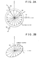
- high-frequency probe voltage is applied to a U-phase stator winding 51, a V-phase stator winding 52, and a W-phase stator winding 53 to form a high-frequency voltage vector (of a consistent magnitude) that rotates in the direction of rotation of a rotor 50 around the origin of ⁇ coordinates which are fixed coordinates with their origin at the center of rotation of the rotor 50.
- the high-frequency voltage vector is a voltage vector that rotates at sufficiently high speed relative to the rotation speed of the rotor 50.
- the inductance of the rotor 50 has a different value at a d-axis, which is a magnetic pole axis in the direction of magnetic flux, than it does at a q-axis which is orthogonal to the d-axis (i.e., an axis in the direction of torque). Therefore, the magnitude of the current vector becomes larger in the direction closer to the d-axis and smaller in the direction closer to the q-axis. As a result, the terminus of the current vector makes an elliptical trajectory 55 with the d-axis direction of the rotor 50 as the major axis on the ⁇ coordinate system, as shown in FIG. 2B .
- the magnitude of the current vector has local maximum values in the directions of the N-pole and S-pole of the rotor 50. That is, the magnitude of the voltage vector changes as shown in FIG. 3B , while the magnitude of the current vector has two local maximum values in a single cycle, as shown in FIG. 3A .
- the effect of magnetic saturation of the stator causes the inductance on the N-pole side of the rotor 50 to be smaller than the inductance on the S-pole side of the rotor 50, so the current vector in the direction of the N-pole assumes the highest value (see curve L1).
- JP-A-2004-343963 describes a method for estimating the rotation angle of a rotor using induced voltage.
- the position estimating method which uses high-frequency probe voltage is not suitable for use in the high speed region where the rotor position can be estimated using induced voltage because efficiency may decrease as a result of the high-frequency probe voltage being applied, which may adversely affect the control of the motor.
- this invention provides a motor controller which can appropriately use low speed region position estimation and high speed region position estimation depending on the rotor rotation speed, and as a result, accurately calculate the rotor position and thus improve the accuracy with which the motor is controlled.
- the invention also provides a vehicular steering system which can appropriately use low speed region position estimation and high speed region position estimation depending on the rotor rotation speed, and as a result, accurately control a motor that applies torque for steering and also improves the steering feel.
- a first aspect of the invention relates to a motor controller that controls a motor provided with a rotor and a stator opposing the rotor.
- This motor controller includes a rotation speed detecting portion that detects the rotation speed of the rotor or a member that rotates together with the rotor; a low speed region position estimating portion which is designed to be suitable for a predetermined low speed region and estimates the rotational position of the rotor; a high speed region position estimating portion which is designed to be suitable for a predetermined high speed region and estimates the rotational position of the rotor; and a rotational position calculating portion which obtains the rotational position of the rotor based on i) the rotation speed detected by the rotation speed detecting portion, ii) the rotational position of the rotor estimated by the low speed region position estimating portion, and iii) the rotational position of the rotor estimated by the high speed region position estimating portion.
- the rotation speed of the rotor or a rotating member that rotates together with the rotor (hereinafter simply referred to as the "rotating speed of the rotor or the like") is detected by the rotation speed detecting portion. That is, instead of obtaining the rotor rotation speed by a calculation using the rotational position of the rotor obtained by estimation, the rotation speed of the rotor or the like is detected. Then the rotational position of the rotor can be obtained using the detected rotation speed of the rotor or the like and the rotational position of the rotor estimated by both the low speed region position estimating portion and the high speed region position estimating portion.
- the rotation speed of the rotor or the like will not be affected even if there is estimation error in the rotational position of the rotor estimated by the low speed region position estimating portion or the high speed region position estimating portion. Therefore, the estimation results from the low speed region position estimating portion and the estimation results from the high speed region position estimating portion can be used appropriately depending on the rotation speed of the rotor or the like so the accuracy of the rotational position of the rotor that is obtained by the rotational position calculating portion can be improved.
- the low speed region position estimating portion may estimate the rotational position of the motor based on the motor current detected by a motor current detecting portion.
- the high speed region position estimating portion may estimate the rotational position of the motor based on the motor current detected by a motor current detecting portion and the motor voltage specified by a motor voltage command portion.
- the induced voltage of the motor can be estimated based on the motor current and motor command voltage and the rotational position of the motor can be estimated based on this estimated induced voltage.
- the rotational position calculating portion may include a selecting portion that selects, according to the detected rotation speed, one of i) the rotational position of the rotor estimated by the low speed region position estimating portion or ii) the rotational position of the rotor estimated by the high speed region position estimating portion.
- the calculation results of the low speed region position estimating portion and the high speed region position estimating portion can be appropriately selected according to the rotation speed of the rotor or the like detected by the rotation speed detecting portion, and any difference in the estimated position will not affect this selection. As a result, the accuracy with which the rotational position of the rotor is calculated can be increased.
- an appropriate rotational position may be estimated by combining the two calculation results. This makes it possible to suppress or prevent a discontinuation in the obtained rotational position, which in turn improves the stability of control when switching between the low speed region position estimation and the high speed region position estimation.
- the rotational position calculating portion may also include a dividing portion that obtains a divided rotational position by internally dividing i) the low speed rotational position obtained by the low speed region position estimating portion and ii) the high speed rotational position obtained by the high speed region position estimating portion in a medium speed region which is between the low speed region and a high speed region, according to the rotation speed obtained by the rotation speed detecting portion.
- the motor controller may also include a rotation speed estimating portion that estimates the rotation speed of the rotor based on i) the rotational position of the rotor calculated by the rotational position calculating portion or ii) the rotational position of the rotor estimated by the high speed region position estimating portion; a comparing portion that compares a rotation speed difference between the estimated rotation speed and the detected rotation speed with a speed difference threshold value; and a position correcting portion that corrects the rotational position obtained by the rotational position calculating portion, based on the detected rotation speed when the rotation speed difference is larger than the speed difference threshold value.
- the estimated rotor rotation speed is obtained based on the rotation speed of the rotor calculated by the rotational position calculating portion or the rotational position of the rotor estimated by the high speed region position estimating portion. Then a rotation speed difference between this estimated rotor rotation speed and the detected rotation speed detected by the rotation speed detecting portion is obtained. A larger rotation speed difference is thought to indicate a large amount of error in the estimated rotor rotational position. Therefore, the rotation speed difference is compared to a speed difference threshold value and if this rotation speed difference is greater than the speed difference threshold value, the rotational position obtained by the rotational position calculating portion is corrected based on the detected rotation speed. As a result, the error in the estimated position can be reduced further.
- the estimated rotational position is corrected when the rotation speed difference is large, thereby minimizing torque pulsation.
- the rotation speed detecting portion may detect the rotation speed every predetermined sampling cycle, and the rotational position calculating portion may calculate the rotational position of the rotor every sampling cycle.
- the position correcting portion adds the product of the sampling cycle multiplied by the rotation speed detected by the rotation speed detecting portion to the last value calculated by the rotational position calculating portion, and the result of that addition (i.e., the sum) may be used as the current calculated value.
- a second aspect of the invention relates to a vehicular steering system that transmits torque generated by a motor to a steering mechanism.
- This vehicular steering system includes a steering sensor that detects a steering angle; a vehicle speed sensor that detects a speed of a vehicle; and the motor controller of the first aspect that controls the motor.
- the rotation speed detecting portion obtains the rotation speed using the detected steering angle; and the rotational position calculating portion obtains the rotational position of the rotor based on i) the detected speed of the vehicle, ii) the detected rotation speed, iii) the rotational position of the rotor estimated by the low speed region position estimating portion, and iv) the rotational position of the rotor estimated by the high speed region position estimating portion.
- the rotation speed detecting portion obtains the rotation speed of the rotor or the like using the steering sensor provided in the vehicular steering system so there is no need to provide special rotation speed detecting portion.
- the rotation speed detecting portion may also obtain the rotation speed of the steering shaft by temporally differentiating the steering angle detected by the steering angle sensor. The thus obtained rotation speed does not use the estimated rotational position but instead uses the steering angle detected by the steering sensor and so is therefore not affected by error in the estimated rotational position.
- the rotational position of the rotor is obtained considering the speed of the vehicle obtained by the vehicle speed sensor.
- the accuracy of the estimated rotor position may be lower than it is when the rotor is operating in the high speed region. Accordingly, in the medium and low speed regions, motor control performance may not be very high so the torque applied to the steering mechanism may become unstable. Therefore, the rotational position of the rotor may also be obtained considering the speed of the vehicle detected by the vehicle speed sensor.
- the rotational position calculating portion may obtain the rotational position of the rotor using the rotational position of the rotor estimated by the low speed region position estimating portion when the detected rotation speed is in a low speed region which includes values equal to or less than a first threshold value, obtain the rotational position of the rotor using both the rotational position of the rotor estimated by the low speed region position estimating portion and the rotational position of the rotor estimated by the high speed region position estimating portion when the detected rotation speed is in a medium speed region which includes values greater than the first threshold value and equal to or less than a second threshold value which is greater than the first threshold value, and obtain the rotational position of the rotor using the rotational position of the rotor estimated by the high speed region position estimating portion when the detected rotation speed is in the high speed region which includes values greater than the second threshold value.
- the rotational position calculating portion may obtain the rotational position of the rotor according to the above process when the detected speed of the vehicle is zero.
- the vehicular steering system may further include a current command value generating portion that sets a current command value for driving the motor based on the detected speed of the vehicle and the detected rotation speed.
- the current command value generating portion may set the current command value to zero to stop driving the motor when the detected speed of the vehicle is not zero and the detected rotation speed is in the low speed region.
- the rotational position calculating portion may obtain the rotational position of the rotor using the rotational position of the rotor estimated by the high speed region position estimating portion when the detected speed of the vehicle is not zero and the detected rotation speed is in the medium speed region or in the high speed region.
- the speed of the vehicle is zero, it does not really matter if the torque generated by the motor is somewhat unstable, but because the steering load is large, it is preferable that the torque generated by the motor be actively transmitted to the steering mechanism. Therefore, when the rotation speed of the rotor or the like is in the low speed region, the rotational position of the rotor is obtained using the rotational position of the rotor estimated by the low speed region position estimating portion. Also, when the rotation speed of the rotor or the like is in the medium speed region, the rotational position of the rotor is obtained using the rotational position of the rotor estimated by both the low speed region position estimating portion and the high speed region position estimating portion.
- the rotational position of the rotor is obtained using the rotational position of the rotor estimated by the high speed region position estimating portion. Steering or steering assist is performed by having the torque generated by driving the motor based on the rotational position of the rotor obtained in this way be transmitted to the steering mechanism.
- the rotor rotation speed is obtained using the rotational position of the rotor estimated by the high speed region position estimating portion.
- the motor stops being driven when the rotation speed of the rotor or the like is in the low speed region.
- the current command value generating portion may reduce the current command value as the rotation speed decreases when the speed of the vehicle detected by the vehicle speed sensor is not zero, and the detected rotation speed is in the medium speed region.
- the accuracy with which the high speed region position estimating portion estimates the rotational position of the rotor decreases as the rotor rotation speed decreases. Therefore, when the vehicle is moving and the rotation speed of the rotor or the like is in the medium speed region, the current command value is reduced as the rotation speed decreases. As a result, an odd steering feel caused by unstable torque being generated by the motor can be reduced.
- FIG. 1 is a block diagram of the electrical configuration of an electric power steering system (i.e., one example of a vehicular steering system) to which a motor controller according to one example embodiment of the invention has been applied.
- an electric power steering system i.e., one example of a vehicular steering system
- a motor controller according to one example embodiment of the invention has been applied.
- This electric power steering system includes a torque sensor 1 that detects steering torque applied to a steering wheel 10 which serves as a steering member for steering a vehicle, a motor 3 (i.e., an electric motor) that applies steering assist force to a steering mechanism 2 of the vehicle, a steering sensor 4 that detects the steering angle which is the rotation angle of the steering wheel 10, a motor controller 5 that controls (i.e., drives) the motor 3, and a vehicle speed sensor 6 that detects the speed of the vehicle provided with the electric power steering system.
- a torque sensor 1 that detects steering torque applied to a steering wheel 10 which serves as a steering member for steering a vehicle
- a motor 3 i.e., an electric motor
- a steering sensor 4 that detects the steering angle which is the rotation angle of the steering wheel 10
- a motor controller 5 that controls (i.e., drives) the motor 3
- a vehicle speed sensor 6 that detects the speed of the vehicle provided with the electric power steering system.
- the motor controller 5 provides appropriate steering assist according to the steering state and vehicle speed by driving the motor 3 according to the steering torque detected by the torque sensor 1 and the vehicle speed detected by the vehicle speed sensor 6.
- the motor 3 in this example embodiment is a three-phase brushless DC motor, and includes a rotor 50 that functions as field system, and a U-phase stator winding 51, a V-phase stator winding 52, and a W-phase stator winding 53 which are provided on a stator opposite the rotor 50, as schematically shown in FIG. 2A .
- the motor 3 may be an inner-rotor type motor in which the stator is arranged opposing, and on the outside of, the rotor, or an outer-rotor type motor in which the stator is arranged opposing, and on the inside of, a cylindrical rotor.
- the motor controller 5 includes a microcomputer 7, a drive circuit (i.e., inverter circuit) that is controlled by the microcomputer 7 and supplies power to the motor 3, and a current sensor 9 that detects current flowing through each phase stator winding of the motor 3.
- the microcomputer 7 includes a CPU and memory (i.e., ROM and RAM and the like) and functions as a plurality of function processing portions by executing predetermined programs.
- the plurality of function processing portions includes a current command value generating portion 11, a PI (proportional integral) control portion 12, a command voltage generating portion 13, a ⁇ / ⁇ coordinate converting portion 14, a ⁇ / UVW coordinate converting portion 15, a PWM control portion 16, a UVW / ⁇ coordinate converting portion 17, a ⁇ / ⁇ coordinate converting portion 18, a deviation calculating portion 19, a position estimating portion 21, a rotation speed estimating portion 22, a high-frequency voltage generating portion 23, and a rotation speed calculating portion 24.
- PI proportional integral
- the current command value generating portion 11 generates a command value I d * of a d-axis current component in the direction of the magnetic pole of the rotor of the motor 3, and a command value I q * of a q-axis current component orthogonal to the d-axis.
- current command value I dq the dq plane of coordinates is a plane in the rotational direction of the rotor 50, and the d-axis and the q-axis define a rotating coordinate system that rotates together with the rotor 50 (see FIG. 2A ).
- the current command value generating portion 11 generates a d-axis current command value I d * of 0 and generates a q-axis current command value I q * that corresponds to the steering torque detected by the torque sensor 1 and the vehicle speed detected by the vehicle speed sensor 6. More specifically, the q-axis current command value I q * may also be generated using a map (i.e., a table) on which is stored q-axis current command values I q * corresponding to the steering torque and the vehicle speed. Because the torque generated by the motor 3 corresponds to the motor current, the current command value I dq can also be referred to as the torque command value that specifies the torque to be generated by the motor.
- the current sensor 9 detects a U-phase current I U , a V-phase current I V , and a W-phase current I W of the motor 3 (hereinafter when these are referred to together, they will collectively be referred to as "three-phase detection current I UVW ".
- This detection value is then applied to the UVW / ⁇ coordinate converting portion 17.
- the UVW / ⁇ coordinate converting portion 17 coordinate-converts the three-phase detection current I UVW into currents I ⁇ and I ⁇ on a two-phase fixed coordinate system (hereinafter when these are referred to together, they will collectively be referred to as "two-phase detection current I ⁇ ).
- the two-phase fixed coordinate system is a fixed coordinate system that has an ⁇ -axis with its origin at the rotational center of the rotor 50, and a ⁇ -axis that is orthogonal to the ⁇ -axis (see FIGS. 2A and 2B ).
- the coordinate-converted two-phase detection current I ⁇ is then applied to the ⁇ / ⁇ coordinate converting portion 18.
- the ⁇ / ⁇ coordinate converting portion 18 coordinate-converts the two-phase detection current I ⁇ into currents I ⁇ and I ⁇ (hereinafter when these are referred to together, they will collectively be referred to as "detection current I ⁇ ") on a rotating coordinate system (y - ⁇ ) in accordance with a rotor rotational position ⁇ that is estimated by the position estimating portion 21 (hereinafter simply referred to as "estimated rotational position ⁇ ").
- This rotating coordinate system ( ⁇ - ⁇ ) is a rotating coordinate system that is defined by a ⁇ -axis in the direction of the magnetic poles of the rotor and an ⁇ -axis orthogonal to the ⁇ -axis, when the rotor 50 is in the estimated rotational position ⁇ .
- the dq rotating coordinate system and the ⁇ rotating coordinate system match up.
- the detection current I ⁇ is then applied to the deviation calculating portion 19.
- This deviation calculating portion 19 calculates the deviation of the ⁇ -axis current I ⁇ with respect to the d-axis current command value I d *, as well as the deviation of the ⁇ -axis current I ⁇ with respect to the q-axis current command value I q *. These deviations are then sent to the PI control portion 12 where they are subjected to a PI calculation process.
- command voltage V ⁇ a ⁇ -axis command voltage V ⁇ * and a ⁇ -axis command voltage V ⁇ * (hereinafter when these are referred to together, they will collectively be referred to as "command voltage V ⁇ ") are generated by the command voltage generating portion 13 according to the calculation results and applied to the ⁇ / ⁇ coordinate converting portion 14.
- the ⁇ / ⁇ coordinate converting portion 14 coordinate-converts the ⁇ -axis command voltage V ⁇ * and the ⁇ -axis command voltage V ⁇ * into an ⁇ -axis command voltage V ⁇ * and a ⁇ -axis command voltage V ⁇ * (hereinafter when these are referred to together, they will collectively be referred to as "two-phase command voltage V ⁇ ") which are command voltages on the two-phase fixed coordinate system.
- This two-phase command voltage V ⁇ is then applied to the ⁇ / UVW coordinate converting portion 15.
- the ⁇ / UVW coordinate converting portion 15 then converts the ⁇ -axis command voltage V ⁇ * and a ⁇ -axis command voltage V ⁇ * into command voltages of a three-phase fixed coordinate system, i.e., a U-phase command voltage V U *, a V-phase command voltage V V *, and a W-phase command voltage V W * (hereinafter when these are referred to together, they will collectively be referred to as "three-phase command voltage V UVW ").
- the PWM control portion 16 generates a drive signal of a duty ratio that is controlled according to the three-phase command voltages V U * V V *, and V W *, and sends this drive signal to the drive circuit 8.
- voltage at a duty ratio corresponding to the U-phase command voltage V U *, the V-phase command voltage V V *, and the W-phase command voltage V W * is applied to the corresponding phases of the motor 3.
- this steering torque is detected by the torque sensor 1.
- the current command value I dq corresponding to that detected steering torque and the vehicle speed detected by the vehicle speed sensor 6 is generated by the current command value generating portion 11.
- the deviation between the current command value I dq and the detection current I ⁇ is obtained by the deviation calculating portion 19 and a PI calculation is performed by the PI control portion 12 so that this deviation becomes zero.
- a command voltage V ⁇ corresponding to this calculation result is generated by the command voltage generating portion 13 and converted into a three-phase command voltage V UVW via the coordinate converting portions 14 and 15.
- the PWM control portion 16 operates the drive circuit 8 at a duty ratio corresponding to that three-phase command voltage V UVW to drive the motor 3 such that assist torque corresponding to the current command value I dq is applied to the steering mechanism 2. In this way, steering assist is performed according to the steering torque.
- the three-phase detection current I UVW detected by the current sensor 9 is then converted into a detection current I ⁇ expressed on the rotating coordinate system (y - ⁇ ) so as to correspond to the current command value I dq , via the coordinate converting portions 17 and 18, after which it is applied to the deviation calculating portion 19.
- phase angle (electrical angle) ⁇ indicative of the rotational position of the rotor 50 is necessary.
- the estimated rotational position ⁇ indicative of this phase angle is generated by the position estimating portion 21 and then sent to the ⁇ / ⁇ coordinate converting portion 14 and the ⁇ / ⁇ coordinate converting portion 18.
- the high-frequency voltage generating portion 23 functions as probe voltage applying portion that applies a probe voltage to the motor 3 to estimate the phase angle ⁇ of the rotor 50 when the rotor 50 is stopped or rotating extremely slowly (i.e., at 250 rpm or less).
- This high-frequency voltage generating portion 23 generates a voltage command value for applying, as the probe voltage, a high-frequency sinusoidal voltage (see FIG. 3B ) of a sufficiently high frequency (such as 200 Hz) compared to the rated frequency of the motor 3 to the U-phase stator winding 51, the V-phase stator winding 52, and the W-phase stator winding 53 of the motor 3, and outputs this voltage command value to the PWM control portion 16.
- a high-frequency sinusoidal voltage see FIG. 3B
- a sufficiently high frequency such as 200 Hz
- a high-frequency voltage vector that rotates around the rotational center of the rotor 50 is applied by repeatedly energizing the V - W phase, the W - U phase, and the U - V phase sequentially by applying the high-frequency voltage at a duty ratio that will not cause the rotor 50 to rotate.
- This high-frequency voltage vector is a voltage vector of a constant magnitude that rotates at a constant speed about the origin of the ⁇ coordinates which are fixed coordinates with their origin at the rotational center of the rotor 50 (see FIG. 2A ).
- the high-frequency voltage generating portion 23 generates a command value for applying the high-frequency voltage (i.e., the probe voltage) described above when the rotor 50 is stopped or rotating extremely slowly, and sends this command value to the PWM control portion 16.
- the high-frequency voltage generating portion 23 stops generating the high-frequency voltage command.
- the rotation speed calculating portion 24 obtains the rotation speed (i.e., the steering angle speed) of a steering shaft 10A by temporally differentiating the steering angle detected by the steering angle sensor 4, and then converts it into the rotation speed ⁇ of the motor 3.
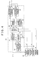
- FIG. 4 is a block diagram of the structure of the position estimating portion 21.
- the position estimating portion 21 estimates the rotational position of the rotor 50 based on i) the motor current running through the motor 3 (i.e., the two-phase detection current I ⁇ ) in this example embodiment) and ii) the motor voltage applied to the motor 3 (i.e., the two-phase command voltage V ⁇ in this example embodiment).
- This position estimating portion 21 includes a low speed region position estimating portion 41, a high speed region position estimating portion 42, a dividing portion 43, a selecting portion 44, and a dividing coefficient calculating portion 47. Moreover, the position estimating portion 21 includes a rotation speed difference calculating portion 71, a comparing portion 72, a position change amount calculating portion 73, and a position correcting portion 74. The dividing portion 43 and the selecting portion 44 function as a rotational position calculating portion.
- the low speed region position estimating portion 41 is designed to be suitable for estimating the position of the rotor 50 when the motor 3 is stopped or operating at an extremely slow speed (such as 0 to 100 rpm). This low speed region position estimating portion 41 estimates the rotational position of the rotor 50 based on the two-phase detection current I ⁇ output from the UVW / ⁇ coordinate converting portion 17 and the two-phase command voltage V ⁇ generated by the ⁇ / ⁇ coordinate converting portion 14.
- the high speed region position estimating portion 42 is designed to be suitable for estimating the position of the rotor 50 when the motor 3 is operating at high speeds (such as 200 rpm or higher).
- This high speed region position estimating portion 42 estimates the rotational position of the rotor 50 based on the two-phase detection current I ⁇ output from the UVW / ⁇ coordinate converting portion 17 and the two-phase command voltage V ⁇ generated by the ⁇ / ⁇ coordinate converting portion 14.
- the dividing portion 43 internally divides the low speed estimated rotational position ⁇ L obtained by the low speed region position estimating portion 41 and the high speed estimated rotational position ⁇ H obtained by the high speed region position estimating portion 42 to obtain a divided estimated rotational position ⁇ M .
- a dividing coefficient ⁇ used in the dividing process of the dividing portion 43 is obtained by the dividing coefficient calculating portion 47.
- the selecting portion 44 selects one from among the low speed estimated rotational position ⁇ L , the high speed estimated rotational position ⁇ H , and the divided estimated rotational position ⁇ M , and outputs it as the estimated rotational position ⁇ .
- the position change amount calculating portion 73 obtains the position change amount ⁇ by multiplying the control cycle T by the rotation speed ⁇ obtained by the rotation speed calculating portion 24.
- This position change amount ⁇ corresponds to the amount of change in the rotor rotational position ⁇ during the control cycle T.
- FIG. 5 is a block diagram of an example structure of the low speed region position estimating portion 41.
- the low speed region position estimating portion 41 includes a high-frequency response extracting portion 38 and a rotor position estimating portion 39.
- the high-frequency response extracting portion 38 receives the two-phase detection current I ⁇ output from the UVW / ⁇ coordinate converting portion 17.
- the high-frequency response extracting portion 38 is, for example, a high-pass filter which performs a filtering process to extract the high-frequency component corresponding to the frequency of the high-frequency voltage generated by the high-frequency voltage generating portion 23 from the signal output by the UVW / ⁇ coordinate converting portion 17.
- the rotor position estimating portion 39 estimates the rotor phase angle ⁇ based on the high-frequency component extracted by the high-frequency response extracting portion 38. This estimating method is just like that described above with reference to FIGS. 2 and 3 .
- the low speed estimated rotational position ⁇ L is obtained according to Expression (3) below using the two-phase command voltages V ⁇ * and V ⁇ * when the current vector is at maximum value, for example.
- FIG 6 is a block diagram of an example structure of the high speed region position estimating portion 42.
- the high speed region position estimating portion 42 includes a signal processing portion 48 and a rotor position estimating portion 49.
- the signal processing portion 48 has a voltage filter 31 formed by a low-pass filter that filters out (i.e., removes) the high-frequency component from the two-phase command voltage V ⁇ , and a current filter 32 formed of a low-pass filter that filters out (i.e., removes) the high-frequency component from the two-phase detection current I ⁇ .
- the rotor position estimating portion 49 receives the two-phase command voltage V ⁇ and the two-phase detection current I ⁇ after signal processing (i.e., filtering) by the signal processing portion 48.
- the rotor position estimating portion 49 has a disturbance observer 25, an estimated value filter 26, and an estimated position generating portion 27.
- the disturbance observer 25 estimates, as disturbance, induced voltage of the motor 3 based on a motor model which is a mathematical model of the motor 3.
- the estimated value filter 26 is formed by a low-pass filter that filters out (i.e., removes) the high-frequency component from the estimated induced voltage output by the disturbance observer 25.
- the estimated position generating portion 27 generates the high speed estimated rotational position ⁇ H of the rotor 50 based on the estimated induced voltage (i.e., the value after filtering) output by the estimated value filter 26.
- the disturbance observer 25 of the rotor position estimating portion 49 receives both the two-phase command voltage V ⁇ filtered by the voltage filter 31 of the signal processing portion 48 and the two-phase detection current I ⁇ filtered by the current filter 32.
- FIG. 7 is a block diagram of an example of the disturbance observer 25 and the structure related thereto.
- the motor model which is a mathematical model of the motor 3 can be expressed as (R + pL) -1 , for example, where R is the armature winding resistance, L is the ⁇ -axis inductance, and p is the differential operator.
- the two-phase command voltage V ⁇ and an induced voltage E ⁇ i.e., a ⁇ -axis induced voltage E ⁇ and a ⁇ -axis induced voltage E ⁇
- E ⁇ i.e., a ⁇ -axis induced voltage E ⁇ and a ⁇ -axis induced voltage E ⁇
- the disturbance observer 25 may be formed by an inverse motor model (i.e., an inverse model of a motor model) 35 that receives the two-phase detection current I ⁇ and estimates the motor voltage, and a voltage deviation calculating portion 36 that obtains the deviation between the motor voltage estimated by the inverse motor model 35 and the two-phase command voltage V ⁇ .
- the voltage deviation calculating portion 36 obtains the disturbance with respect to the two-phase command voltage V ⁇ .
- this disturbance is an estimated value E ⁇ ⁇ (i.e., ⁇ -axis induced voltage estimated value E ⁇ ⁇ and ⁇ -axis induced voltage estimated value E ⁇ ⁇ (hereinafter collectively be referred to as "estimated induced voltage E ⁇ ⁇ ”)) that corresponds to the induced voltage E ⁇ .
- the inverse motor model 35 may be expressed by R + pL, for example.
- the estimated value filter 26 may be formed by a low-pass filter that may be expressed by a / (s + a), where a is a design parameter that determines the cutoff frequency ⁇ c of the estimated value filter 26.
- the induced voltage E ⁇ can be expressed by Expression (4) below, where K E is an induced voltage constant, ⁇ is the rotational position of the rotor, and ⁇ is the rotor rotation speed.
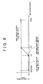
- FIG. 8 is a graph showing a process performed by the dividing portion 43 and the selecting portion 44.
- the horizontal axis represents the rotation speed of the motor 3 and the vertical axis represents the utilization rate of the high speed estimated rotational position ⁇ H obtained by the high speed region position estimating portion 42.
- FIG. 8 shows an operation when the vehicle speed detected by the vehicle speed sensor 6 is zero, i.e., when the vehicle is stopped.
- the speed region of the rotation speed ⁇ of the motor 3 (i.e., of the rotation speed ⁇ calculated by the rotation speed calculating portion 24) is divided into three regions, i.e., a low speed region ( ⁇ ⁇ ⁇ TL ) from a stopped state to a first threshold value ⁇ TL , a medium speed ( ⁇ TL ⁇ ⁇ ⁇ ⁇ TH ) from the first threshold value ⁇ TL to a second threshold value ⁇ TH (where ⁇ TH > ⁇ TL ), and a high speed region ( ⁇ TH ⁇ ⁇ ) that exceeds the second threshold value ⁇ TH .
- the low speed region position estimating portion 41 is designed to be able to estimate the rotor rotational position within a predetermined accuracy range in the low and medium speed regions.
- the high speed region position estimating portion 42 is designed to be able to estimate the rotor rotational position within a predetermined accuracy range in the medium and high speed regions. Therefore, in the medium speed region, both the low speed region position estimating portion 41 and the high speed region position estimating portion 42 are able to perform a calculation to estimate the rotor position. However, these calculation results are not always the same, rather, the calculation results usually differ.
- the selecting portion 44 selects the low speed estimated rotational position ⁇ L obtained by the low speed region position estimating portion 41 and outputs it. Therefore, the utilization rate of the high speed estimated rotational position ⁇ H in this case is zero.
- the selecting portion 44 selects the divided estimated rotational position ⁇ M obtained by the dividing portion 43 and outputs it.
- the selecting portion 44 selects the high speed estimated rotational position ⁇ H obtained by the high speed region position estimating portion 42 and outputs it. Therefore, the utilization rate of the high speed estimation rotational position ⁇ H in this case is 1 (100%).
- the dividing portion 43 effectively functions in the medium speed region.
- the dividing portion 43 obtains the divided estimated rotational position ⁇ M according to Expression (6) below.
- ⁇ ⁇ M 1 - ⁇ ⁇ ⁇ ⁇ L + ⁇ ⁇ ⁇ ⁇ H
- the dividing coefficient ⁇ is calculated by the dividing coefficient calculating portion 47 and indicates the utilization rate of the high speed estimated rotational position ⁇ H .
- the term (1 - ⁇ ) indicates the utilization rate of the low speed estimated rotational position ⁇ L .
- the dividing coefficient ⁇ can be variably set according to the rotation speed ⁇ calculated by the rotation speed calculating portion 24.
- the dividing coefficient ⁇ is calculated by the dividing coefficient calculating portion 47 to be larger as the rotation speed ⁇ increases, and is output to the dividing portion 43. More specifically, the dividing coefficient ⁇ is set to change linearly within a range from 0 to 1 according to the rotation speed ⁇ between the first threshold value ⁇ TL and the second threshold value ⁇ TH , for example.
- FIG. 9 is a flowchart illustrating a routine according to which the microcomputer 7 estimates the rotational position of the rotor. This routine is repeatedly executed each control cycle mainly by the position estimating portion 21.
- the two-phase detection current I ⁇ calculated by the UVW / ⁇ coordinate converting portion 17 and the two-phase command voltage V ⁇ calculated by the ⁇ / ⁇ coordinate converting portion 14 are received by the low speed region position estimating portion 41 and the high speed region position estimating portion 42 (step S1).
- the rotation speed calculating portion 24 obtains the steering angle speed based on the difference between the steering angle detected by the steering sensor 4 in the current control cycle n and the steering angle detected by the steering angle sensor 4 in the last control cycle n - 1, and then converts this steering angle speed into the rotation speed ⁇ of the rotor (step S2).
- step S3 it is determined whether the speed V of the vehicle detected by the vehicle speed sensor 6 is zero (step S3). If the speed V of the vehicle is zero (i.e., YES in step S3), i.e., if the vehicle is stopped, it is determined whether the rotation speed ⁇ is in the low speed region, the medium speed region, or the high speed region (steps S4 and S5).
- a low speed estimated rotational position ⁇ L is obtained by the low speed region position estimating portion 41 (step S6) and this low speed estimated rotational position ⁇ L is output from the selecting portion 44 as the estimated rotational position ⁇ (step S7).
- a high speed estimated rotational position ⁇ H is obtained by the high speed region position estimating portion 42 (step S8) and this high speed estimated rotational position ⁇ H is output from the selecting portion 44 as the estimated rotational position ⁇ (step S9).
- a low speed estimated rotational position ⁇ L is obtained by the low speed region position estimating portion 41 (step S10) and a high speed estimated rotational position ⁇ H is obtained by the high speed region position estimating portion 42 (step S11). Then the internal dividing point between the low speed estimated rotational position ⁇ L and the high speed estimated rotational position ⁇ H is obtained by the dividing portion 43 which then calculates the divided estimated rotational position ⁇ M (step S12). This divided estimated rotational position ⁇ M is then output from the selecting portion 44 as the estimated rotational position ⁇ (step S13).
- the rotation speed difference calculating portion 71 obtains the rotation speed difference ⁇ between the estimated rotation speed ⁇ and the rotor rotation speed ⁇ obtained by the rotation speed calculating portion 24 (step S15).
- the comparing portion 72 compares the rotation speed difference ⁇ with a speed difference threshold value (such as a value corresponding to 10 degrees when converted to a rotation angle difference ⁇ T during one control cycle) (step S16). If the rotation speed difference ⁇ is equal to or less than the speed difference threshold value (i.e., NO in step S16), the estimated rotational position ⁇ (n) output from the selecting portion 44 in the current control cycle n is used as it is.
- a speed difference threshold value such as a value corresponding to 10 degrees when converted to a rotation angle difference ⁇ T during one control cycle
- the selecting portion 44 determines whether the rotation speed ⁇ is equal to or less than the first threshold value ⁇ TL , i.e., whether the rotation speed ⁇ is a value in the low speed region (step S18). If the rotation speed ⁇ exceeds the first threshold value ⁇ TL (i.e., NO in step S18), i.e., if the rotation speed ⁇ is a value in the medium or high region, the selecting portion 44 selects the high speed estimated rotational position ⁇ H as the estimated rotational position ⁇ (n) for the current cycle (step S19).
- step 14 If, on the other hand, the rotation speed ⁇ is equal to or less than the first threshold value ⁇ TL (i.e., YES in step S18), i.e., if the rotation speed ⁇ is a value in the low speed region, this control cycle directly ends without the selecting portion 44 selecting any of the estimated rotational positions.
- the first threshold value ⁇ TL i.e., YES in step S18
- FIG. 10 is a flowchart illustrating a routine for setting the current command value I dq based on the speed V of the vehicle and the rotor rotation speed ⁇ .
- the current command value generating portion 11 sets the current command value I dq based on the steering torque detected by the torque sensor 1 and the vehicle speed V detected by the vehicle speed sensor 6, according to a predetermined assist map (step S31).
- the current command value generating portion 11 determines whether the vehicle speed V is zero (step S32). If the vehicle speed V is zero (i.e., YES in step S32), the current command value I dq obtained in step S1 is used as it is.
- the current command value generating portion 11 determines whether the rotation speed ⁇ is equal to or less than the first threshold value ⁇ TL , i.e., whether the rotation speed ⁇ is a value in the low speed region (step S33). If the vehicle speed V is not zero and the rotation speed ⁇ is a value in the low speed region (i.e., YES in step S33), the current command value generating portion 11 sets the current command value I dq to zero (step S34). That is, the motor 3 is not driven.
- the current command value generating portion 11 determines whether the rotation speed ⁇ exceeds the second threshold value ⁇ TH (step S35). If the determination is YES, i.e., if the rotation speed ⁇ is in the high speed region, the current command value I dq obtained in step S1 is used as it is.
- step S35 If, on the other hand, the determination in step S35 is NO and it is determined that the rotation speed ⁇ is a value in the medium speed region, the current command value I dq obtained in step S1 is corrected by being multiplied by a predetermined correction coefficient C ⁇ (0 ⁇ C ⁇ ⁇ 1) (step S36).
- This correction coefficient C ⁇ is set to become smaller as the rotation speed ⁇ decreases. Therefore, in the medium speed region, the current command value I dq becomes smaller as the rotation speed ⁇ decreases.
- the rotation speed ⁇ of the rotor is obtained using a signal output from the steering sensor 4, and one of the low speed estimated rotational position ⁇ L , the high speed estimated rotational position ⁇ H , or the divided estimated rotational position ⁇ M is selected based on that obtained rotor rotation speed ⁇ .
- the dividing coefficient ⁇ for obtaining the divided estimated rotational position ⁇ M is determined based on the rotation speed ⁇ . Therefore, even if there is error in the estimated rotational position ⁇ , an appropriate estimated value can be selected and an appropriate dividing process can be performed, based on the rotation speed ⁇ which is not affected by that error. As a result, the rotor position can be estimated more accurately.
- the motor 3 is controlled by actively using the estimated rotational position ⁇ .
- the motor control using the estimated rotational position ⁇ is suppressed because the accuracy with which the position is estimated is not very good when the rotor rotation speed ⁇ is on the low speed side.
- steering assist can be performed appropriately by driving the motor 3, and when the vehicle is moving, an odd steering sensation can be reduced, thereby improving the steering feel.
- the structure of the low speed region position estimating portion 41 may also be as shown in FIG. 11 .
- the signal output from the high-frequency response extracting portion 38 is further filtered by a filter 40 before it is received by the rotor position estimating portion 39.
- the filter 40 is a filter that has a passband of around twice the high-frequency voltage applied by the high-frequency voltage generating portion 23.
- the response current waveform with respect to the high-frequency rotation voltage has peaks corresponding to the N and S poles of the rotor so the waveform has a frequency almost twice that of the high-frequency rotation voltage. Therefore, a signal of the necessary frequency can be amplified and detected by applying a filter in which the gain is increased for a frequency that is twice the frequency of the high-frequency rotation voltage.
- the calculation of the estimated rotational position ⁇ and the setting of the current control value I dq are different when the vehicle is stopped compared with when the vehicle is moving.
- the calculation of the estimated rotational position ⁇ and the setting of the current control value I dq may be the same regardless of whether the vehicle is stopped or moving. More specifically, steps S3, S18, and S19 in FIG. 9 and steps S32 to S36 in FIG. 10 may be omitted.
- the estimated rotational position ⁇ is obtained by internally dividing the low speed estimated rotational position ⁇ L and the high speed estimated rotational position ⁇ H .
- either the low speed estimated rotational position ⁇ L or the high speed estimated rotational position ⁇ H may be selected by the selecting portion 44 without performing this kind of internal division.
- the probe high-frequency voltage is superimposed on the three-phase command voltage V UVW in the foregoing example embodiment.
- the probe high-frequency voltage may be superimposed on the command voltage V ⁇ generated by the command voltage generating portion 13.
- the rotation speed estimating portion 22 obtains the estimated rotation speed ⁇ using the estimated rotational position ⁇ generated by the position estimating portion 21.
- the rotation speed estimating portion 22 may obtain the estimated rotation speed ⁇ using the high speed estimated rotational position ⁇ H generated by the high speed region position estimating portion 42.
- the correction of the estimated rotational position ⁇ by the position correcting portion 74 may be limited to when the rotor is rotating in the medium or high speed region.
- a difference (i.e., displacement) between the estimated rotational position ⁇ and the actual rotational position of the rotor tends to occur when there is a sudden change in speed or during high speed rotation so the estimated rotational position ⁇ can be effectively corrected and torque pulsation due to that displacement effectively minimized with the foregoing structure as well.
- the rotor rotation speed ⁇ can be obtained using the steering angle detected by the steering sensor 4 so the rotor rotational position ⁇ can also be obtained using this rotor rotation speed ⁇ . More specifically, the initial position of the rotor can be detected and the rotational position ⁇ of the rotor obtained based on this initial position of the rotor and the rotor rotation speed ⁇ .
- the initial position of the rotor can be detected by mounting a Hall sensor in a position where output can be obtained near the center or neutral position of the steering wheel 10, for example.
- One reason for mounting the Hall sensor near the center or neutral position of the steering wheel 10 is that it enables the output signal from the Hall sensor to be stably received.
- the rotational position ⁇ of the rotor can be obtained by adding the product ⁇ x T of the rotor rotation speed ⁇ multiplied by the control cycle T to the initial position of the rotor.
- the rotor rotational position ⁇ can be obtained using the output from the steering sensor 4 in the event that this position sensor fails.
- control of the brushless motor can be continued using the rotor rotational position ⁇ obtained in this way.
- assist control may be performed by rotating the motor 3 at a constant speed according to the output signal from the torque sensor 1.
- the output of the torque sensor 1 may be used instead of the output of the steering sensor 4 to obtain the rotor rotation speed ⁇ .
- the torque sensor 1 detects an angular difference between an input shaft side rotation angle ⁇ i and an output shaft side rotation angle ⁇ o of a torsion bar interposed in the steering shaft 10A.
- Th' / k + ⁇ o ⁇ i (where ⁇ i is the input shaft side rotation speed and ⁇ o is the output shaft side rotation speed. Therefore, the rotation speed ⁇ i of the steering shaft 10A can be obtained from the rate of change in (or change in acceleration) of the steering torque Th detected by the torque sensor 1, and this rotation speed ⁇ i can be converted into the rotor rotation speed ⁇ .
- the rotor rotational position ⁇ can also be calculated using the rotor rotation speed ⁇ obtained based on the output of the torque sensor 1.
- the initial position of the rotor can be detected by, for example, applying a high-frequency signal from the high-frequency voltage generating portion 23 when there is no steering torque, and checking the current response at that time.
- the initial position of the rotor may be detected periodically when there has been no detected signal from the torque sensor 1 for a fixed period of time or longer, for example, and the median value from among the values obtained over a plurality of times may be determined to be the initial position of the rotor.
- the invention is applied to control the motor 3 which serves as the driving source for the electric power steering system.
- the invention may also be applied to control of a motor for an electric pump type hydraulic power steering system or motor control used for a purpose other than a power steering system.
- various design changes within the scope of the appended claims for patent are also possible.
- a low speed region position estimating portion 41 is designed to be suitable for when the motor is operating in a low speed region, and estimates a low speed estimated rotational position ⁇ L .
- a high speed region position estimating portion 42 is designed to be suitable for when the motor is operating in a high speed region, and estimates a high speed estimated rotational position ⁇ H .
- a dividing portion 43 obtains a divided estimated rotational position ⁇ M by internally dividing the low speed estimated rotational position ⁇ L and the high speed estimated rotational position ⁇ H .
- a rotation speed calculating portion 24 obtains a rotation speed ⁇ of a rotor based on an output signal from a steering sensor 4. The rotational position of the rotor is then obtained by selecting one of i) the low speed estimated rotational position ⁇ L , the high speed estimated rotational position ⁇ H , or the divided estimated rotational position ⁇ M , based on that rotation speed ⁇ .
Landscapes
- Engineering & Computer Science (AREA)
- Power Engineering (AREA)
- Chemical & Material Sciences (AREA)
- Combustion & Propulsion (AREA)
- Transportation (AREA)
- Mechanical Engineering (AREA)
- Control Of Motors That Do Not Use Commutators (AREA)
- Power Steering Mechanism (AREA)
- Control Of Ac Motors In General (AREA)
- Control Of Electric Motors In General (AREA)
Applications Claiming Priority (1)
| Application Number | Priority Date | Filing Date | Title |
|---|---|---|---|
| JP2008019535A JP5435252B2 (ja) | 2008-01-30 | 2008-01-30 | 車両用操舵装置 |
Publications (2)
| Publication Number | Publication Date |
|---|---|
| EP2086106A2 true EP2086106A2 (de) | 2009-08-05 |
| EP2086106A3 EP2086106A3 (de) | 2015-09-02 |
Family
ID=40352057
Family Applications (1)
| Application Number | Title | Priority Date | Filing Date |
|---|---|---|---|
| EP09151634.4A Withdrawn EP2086106A3 (de) | 2008-01-30 | 2009-01-29 | Motorregler und Fahrzeuglenkungssystems und Motorregler dazu |
Country Status (3)
| Country | Link |
|---|---|
| US (1) | US8154231B2 (de) |
| EP (1) | EP2086106A3 (de) |
| JP (1) | JP5435252B2 (de) |
Cited By (10)
| Publication number | Priority date | Publication date | Assignee | Title |
|---|---|---|---|---|
| EP2322408A3 (de) * | 2009-11-16 | 2011-07-06 | Jtekt Corporation | Motorsteuereinheit und Fahrzeuglenksystem |
| US8855858B2 (en) | 2009-11-12 | 2014-10-07 | Jtekt Corporation | Motor control unit and vehicle steering system |
| US8855857B2 (en) | 2009-01-30 | 2014-10-07 | Jtekt Corporation | Electric motor controller and electric motor controller for vehicle steering apparatus |
| US8862323B2 (en) | 2008-06-30 | 2014-10-14 | Jtekt Corporation | Motor control device and vehicle-steering device comprising same |
| US8862322B2 (en) | 2009-07-06 | 2014-10-14 | Jtekt Corporation | Motor control unit and vehicle steering apparatus |
| US8874316B2 (en) | 2010-08-23 | 2014-10-28 | Jtekt Corporation | Vehicle steering system |
| US8874318B2 (en) | 2009-03-12 | 2014-10-28 | Jtekt Corporation | Motor control unit and motor control unit for vehicle steering apparatus |
| US8892306B2 (en) | 2009-11-17 | 2014-11-18 | Jtekt Corporation | Motor control unit and vehicle steering system |
| WO2015093056A1 (en) * | 2013-12-20 | 2015-06-25 | Hitachi Koki Co., Ltd. | Motor-drive controlling device, power tool, and motor-drive controlling method |
| EP2424105A3 (de) * | 2010-08-31 | 2018-03-28 | Hitachi Industrial Equipment Systems Co., Ltd. | Vektorsteuerungsvorrichtung und Motorsteuersystem |
Families Citing this family (28)
| Publication number | Priority date | Publication date | Assignee | Title |
|---|---|---|---|---|
| JP4706324B2 (ja) * | 2005-05-10 | 2011-06-22 | トヨタ自動車株式会社 | モータ駆動システムの制御装置 |
| JP4928855B2 (ja) * | 2006-07-05 | 2012-05-09 | 株式会社東芝 | 同期機のセンサレス制御装置 |
| JP5641299B2 (ja) * | 2009-10-28 | 2014-12-17 | 株式会社ジェイテクト | モータ制御装置および車両用操舵装置 |
| EP2372312B1 (de) * | 2010-03-31 | 2013-11-20 | SICK STEGMANN GmbH | Feedback-Anordnung und Feedback-Verfahren zur Regelung eines Servomotors |
| DE102010038295A1 (de) * | 2010-07-22 | 2012-01-26 | Robert Bosch Gmbh | Verfahren und Vorrichtung zur sensorlosen Lageerkennung einer elektronisch kommutierten elektrischen Maschine |
| JP5772359B2 (ja) * | 2011-08-02 | 2015-09-02 | 株式会社ジェイテクト | モータ制御装置及び電動パワーステアリング装置 |
| US8935019B2 (en) * | 2011-08-23 | 2015-01-13 | Sygnet Rail Technologies, Llc | Apparatus and method for power production, control, and/or telematics, suitable for use with locomotives |
| CN103192868B (zh) * | 2012-01-06 | 2015-09-30 | 联创汽车电子有限公司 | 汽车电动助力转向系统 |
| JP5877733B2 (ja) * | 2012-02-28 | 2016-03-08 | カルソニックカンセイ株式会社 | 電動モータの制御装置 |
| CN103840725B (zh) * | 2012-11-26 | 2016-05-18 | 台达电子工业股份有限公司 | 永磁同步电机转子位置偏差测量装置及方法 |
| ITTO20130129A1 (it) * | 2013-02-15 | 2014-08-16 | Magna Closures Spa | Sistema e metodo per controllare un motore elettrico senza spazzole in corrente continua a pilotaggio sinusoidale per un attuatore di potenza automobilistico |
| US20150084576A1 (en) * | 2013-05-03 | 2015-03-26 | Texas Instruments Incorporated | Low Speed and High Speed Controller Architecture for Electric Motors |
| KR101769649B1 (ko) * | 2013-09-02 | 2017-08-18 | 엘에스산전 주식회사 | 인버터 시스템에서 전력 케이블의 상태 검출 방법 |
| JP2015136237A (ja) * | 2014-01-17 | 2015-07-27 | 株式会社安川電機 | 回転電機制御装置、回転電機制御方法、及び制御マップの作成方法 |
| JP2016021800A (ja) * | 2014-07-14 | 2016-02-04 | 株式会社リコー | 位置推定装置、モータ駆動制御装置及び位置推定方法 |
| CN107078675A (zh) * | 2015-01-28 | 2017-08-18 | 株式会社东芝 | 逆变器控制装置以及电机驱动系统 |
| CN104967387B (zh) * | 2015-06-23 | 2018-01-05 | 合肥工业大学 | 一种光伏水泵系统转速调节器的在线学习优化设计方法 |
| JP6460927B2 (ja) * | 2015-06-29 | 2019-01-30 | 日立オートモティブシステムズ株式会社 | 電動パワーステアリング装置の制御装置及び電動パワーステアリング装置 |
| JP6580899B2 (ja) * | 2015-08-26 | 2019-09-25 | 株式会社東芝 | ドライブシステムおよびインバータ装置 |
| JP6596321B2 (ja) * | 2015-12-15 | 2019-10-23 | ローム株式会社 | モータの駆動回路、駆動方法、電子機器 |
| US10598517B2 (en) * | 2017-02-14 | 2020-03-24 | Nidec Sankyo Corporation | Rotary encoder |
| KR20180102261A (ko) * | 2017-03-07 | 2018-09-17 | 엘에스산전 주식회사 | 전동기 회전자의 초기위치 추정장치 |
| JP6568160B2 (ja) | 2017-07-28 | 2019-08-28 | ファナック株式会社 | モータ制御装置 |
| JP6538773B2 (ja) | 2017-07-28 | 2019-07-03 | ファナック株式会社 | モータ制御装置 |
| JP6568159B2 (ja) | 2017-07-28 | 2019-08-28 | ファナック株式会社 | モータ制御装置 |
| KR101941976B1 (ko) * | 2017-09-19 | 2019-01-24 | 서울대학교산학협력단 | 전동기 제어장치 |
| JP7077032B2 (ja) * | 2018-02-01 | 2022-05-30 | 日立Astemo株式会社 | 三相同期電動機の制御装置 |
| JP6730377B2 (ja) | 2018-06-28 | 2020-07-29 | ファナック株式会社 | モータ制御装置 |
Citations (1)
| Publication number | Priority date | Publication date | Assignee | Title |
|---|---|---|---|---|
| JP2004343963A (ja) | 2003-05-19 | 2004-12-02 | Honda Motor Co Ltd | ブラシレスdcモータの制御装置 |
Family Cites Families (14)
| Publication number | Priority date | Publication date | Assignee | Title |
|---|---|---|---|---|
| JPH05211793A (ja) * | 1992-01-30 | 1993-08-20 | Mitsubishi Heavy Ind Ltd | 広帯域サーボ装置 |
| JP3506810B2 (ja) * | 1995-06-19 | 2004-03-15 | ユニシア ジェーケーシー ステアリングシステム株式会社 | 電動ポンプ式動力舵取装置 |
| JP3486326B2 (ja) * | 1997-06-23 | 2004-01-13 | トヨタ自動車株式会社 | 同期モータの運転制御方法およびその装置 |
| JP2002051580A (ja) * | 2000-08-03 | 2002-02-15 | Matsushita Electric Ind Co Ltd | 同期モータの位置センサレス制御方法および位置センサレス制御装置。 |
| JP3695342B2 (ja) * | 2001-04-11 | 2005-09-14 | 株式会社日立製作所 | 電動機の制御装置 |
| JP3755424B2 (ja) * | 2001-05-31 | 2006-03-15 | トヨタ自動車株式会社 | 交流電動機の駆動制御装置 |
| JP2003040119A (ja) | 2001-07-26 | 2003-02-13 | Koyo Seiko Co Ltd | 車両用操舵装置 |
| JP4232421B2 (ja) * | 2002-09-19 | 2009-03-04 | アイシン・エィ・ダブリュ株式会社 | 電動機械制御装置、電動機械制御方法及びプログラム |
| US6924617B2 (en) * | 2003-06-23 | 2005-08-02 | General Motors Corporation | Position sensorless control algorithm for AC machine |
| JP4488708B2 (ja) * | 2003-09-26 | 2010-06-23 | 株式会社東芝 | 回転機制御装置および洗濯機 |
| JP2005304175A (ja) * | 2004-04-12 | 2005-10-27 | Yaskawa Electric Corp | 電動機の速度制御装置 |
| JP2006304478A (ja) * | 2005-04-20 | 2006-11-02 | Nsk Ltd | モータ駆動制御装置及びそれを用いた電動パワーステアリング装置 |
| JP2007143213A (ja) * | 2005-11-15 | 2007-06-07 | Shimadzu Corp | Dcブラシレスモータ装置および回転真空ポンプ |
| JP2007307940A (ja) * | 2006-05-16 | 2007-11-29 | Jtekt Corp | 電動パワーステアリング装置 |
-
2008
- 2008-01-30 JP JP2008019535A patent/JP5435252B2/ja not_active Expired - Fee Related
-
2009
- 2009-01-27 US US12/360,217 patent/US8154231B2/en not_active Expired - Fee Related
- 2009-01-29 EP EP09151634.4A patent/EP2086106A3/de not_active Withdrawn
Patent Citations (1)
| Publication number | Priority date | Publication date | Assignee | Title |
|---|---|---|---|---|
| JP2004343963A (ja) | 2003-05-19 | 2004-12-02 | Honda Motor Co Ltd | ブラシレスdcモータの制御装置 |
Cited By (11)
| Publication number | Priority date | Publication date | Assignee | Title |
|---|---|---|---|---|
| US8862323B2 (en) | 2008-06-30 | 2014-10-14 | Jtekt Corporation | Motor control device and vehicle-steering device comprising same |
| US8855857B2 (en) | 2009-01-30 | 2014-10-07 | Jtekt Corporation | Electric motor controller and electric motor controller for vehicle steering apparatus |
| US8874318B2 (en) | 2009-03-12 | 2014-10-28 | Jtekt Corporation | Motor control unit and motor control unit for vehicle steering apparatus |
| US8862322B2 (en) | 2009-07-06 | 2014-10-14 | Jtekt Corporation | Motor control unit and vehicle steering apparatus |
| US8855858B2 (en) | 2009-11-12 | 2014-10-07 | Jtekt Corporation | Motor control unit and vehicle steering system |
| EP2322408A3 (de) * | 2009-11-16 | 2011-07-06 | Jtekt Corporation | Motorsteuereinheit und Fahrzeuglenksystem |
| US8874315B2 (en) | 2009-11-16 | 2014-10-28 | Jtekt Corporation | Motor control unit and vehicle steering system |
| US8892306B2 (en) | 2009-11-17 | 2014-11-18 | Jtekt Corporation | Motor control unit and vehicle steering system |
| US8874316B2 (en) | 2010-08-23 | 2014-10-28 | Jtekt Corporation | Vehicle steering system |
| EP2424105A3 (de) * | 2010-08-31 | 2018-03-28 | Hitachi Industrial Equipment Systems Co., Ltd. | Vektorsteuerungsvorrichtung und Motorsteuersystem |
| WO2015093056A1 (en) * | 2013-12-20 | 2015-06-25 | Hitachi Koki Co., Ltd. | Motor-drive controlling device, power tool, and motor-drive controlling method |
Also Published As
| Publication number | Publication date |
|---|---|
| US20090190903A1 (en) | 2009-07-30 |
| JP2009183063A (ja) | 2009-08-13 |
| JP5435252B2 (ja) | 2014-03-05 |
| EP2086106A3 (de) | 2015-09-02 |
| US8154231B2 (en) | 2012-04-10 |
Similar Documents
| Publication | Publication Date | Title |
|---|---|---|
| US8154231B2 (en) | Motor controller and vehicular steering system using said motor controller | |
| JP4674525B2 (ja) | 磁極位置推定方法及びモータ制御装置 | |
| JP5365701B2 (ja) | 電動パワーステアリング装置 | |
| US8862322B2 (en) | Motor control unit and vehicle steering apparatus | |
| JP5273451B2 (ja) | モータ制御装置 | |
| JP5168536B2 (ja) | モータ制御装置 | |
| US20030128009A1 (en) | Motor control apparatus and method | |
| JP4263582B2 (ja) | ブラシレスモータ制御装置 | |
| JP5267848B2 (ja) | モータ制御装置 | |
| EP2662976B1 (de) | Motorsteuervorrichtung | |
| JP5614598B2 (ja) | モータ制御装置 | |
| JP5252190B2 (ja) | モータ制御装置 | |
| US20060145652A1 (en) | Motor drive controlling device and electric power-steering device | |
| JP5273450B2 (ja) | モータ制御装置 | |
| JP2010029030A (ja) | モータ制御装置 | |
| JP5170505B2 (ja) | モータ制御装置 | |
| JP5392530B2 (ja) | モータ制御装置 | |
| EP2755319A1 (de) | Antriebssystem für einen synchronmotor | |
| JP5908205B2 (ja) | 回転センサレス制御装置 | |
| JP2010178609A (ja) | モータ制御装置 | |
| JP2002320397A (ja) | モータ回転子の位置推定装置、位置推定方法およびプログラム | |
| JP5412772B2 (ja) | 回転機の制御装置 | |
| JP2009100544A (ja) | モータ制御装置 | |
| JP2011230531A (ja) | モータ制御装置 | |
| JP5228435B2 (ja) | インバータ制御装置とその制御方法 |
Legal Events
| Date | Code | Title | Description |
|---|---|---|---|
| PUAI | Public reference made under article 153(3) epc to a published international application that has entered the european phase |
Free format text: ORIGINAL CODE: 0009012 |
|
| AK | Designated contracting states |
Kind code of ref document: A2 Designated state(s): AT BE BG CH CY CZ DE DK EE ES FI FR GB GR HR HU IE IS IT LI LT LU LV MC MK MT NL NO PL PT RO SE SI SK TR |
|
| AX | Request for extension of the european patent |
Extension state: AL BA RS |
|
| PUAL | Search report despatched |
Free format text: ORIGINAL CODE: 0009013 |
|
| AK | Designated contracting states |
Kind code of ref document: A3 Designated state(s): AT BE BG CH CY CZ DE DK EE ES FI FR GB GR HR HU IE IS IT LI LT LU LV MC MK MT NL NO PL PT RO SE SI SK TR |
|
| AX | Request for extension of the european patent |
Extension state: AL BA RS |
|
| RIC1 | Information provided on ipc code assigned before grant |
Ipc: B62D 5/04 20060101ALI20150729BHEP Ipc: H02P 21/00 20060101ALI20150729BHEP Ipc: H02P 21/04 20060101AFI20150729BHEP Ipc: H02P 21/14 20060101ALI20150729BHEP |
|
| 17P | Request for examination filed |
Effective date: 20160302 |
|
| RBV | Designated contracting states (corrected) |
Designated state(s): AT BE BG CH CY CZ DE DK EE ES FI FR GB GR HR HU IE IS IT LI LT LU LV MC MK MT NL NO PL PT RO SE SI SK TR |
|
| AKX | Designation fees paid |
Designated state(s): DE FR |
|
| AXX | Extension fees paid |
Extension state: RS Extension state: BA Extension state: AL |
|
| STAA | Information on the status of an ep patent application or granted ep patent |
Free format text: STATUS: THE APPLICATION HAS BEEN WITHDRAWN |
|
| 18W | Application withdrawn |
Effective date: 20160513 |