EP2060486A1 - Rudder for ships with high speeds with a cavitation reducing, twisted, in particular floating rudder - Google Patents
Rudder for ships with high speeds with a cavitation reducing, twisted, in particular floating rudder Download PDFInfo
- Publication number
- EP2060486A1 EP2060486A1 EP08018925A EP08018925A EP2060486A1 EP 2060486 A1 EP2060486 A1 EP 2060486A1 EP 08018925 A EP08018925 A EP 08018925A EP 08018925 A EP08018925 A EP 08018925A EP 2060486 A1 EP2060486 A1 EP 2060486A1
- Authority
- EP
- European Patent Office
- Prior art keywords
- rudder blade
- rudder
- side wall
- sections
- nose
- Prior art date
- Legal status (The legal status is an assumption and is not a legal conclusion. Google has not performed a legal analysis and makes no representation as to the accuracy of the status listed.)
- Granted
Links
- 230000007704 transition Effects 0.000 claims description 20
- 229910000831 Steel Inorganic materials 0.000 claims description 8
- 239000010959 steel Substances 0.000 claims description 8
- 239000000463 material Substances 0.000 claims description 7
- 230000007423 decrease Effects 0.000 description 6
- 230000008901 benefit Effects 0.000 description 5
- XLYOFNOQVPJJNP-UHFFFAOYSA-N water Substances O XLYOFNOQVPJJNP-UHFFFAOYSA-N 0.000 description 4
- 240000006240 Linum usitatissimum Species 0.000 description 3
- 230000006378 damage Effects 0.000 description 3
- 230000003628 erosive effect Effects 0.000 description 3
- 238000005452 bending Methods 0.000 description 2
- 230000000295 complement effect Effects 0.000 description 2
- 238000010276 construction Methods 0.000 description 2
- 229920003266 Leaf® Polymers 0.000 description 1
- 230000001133 acceleration Effects 0.000 description 1
- 230000015572 biosynthetic process Effects 0.000 description 1
- 230000003247 decreasing effect Effects 0.000 description 1
- 230000001419 dependent effect Effects 0.000 description 1
- 238000006073 displacement reaction Methods 0.000 description 1
- 230000000694 effects Effects 0.000 description 1
- 238000005242 forging Methods 0.000 description 1
- 239000000446 fuel Substances 0.000 description 1
- 230000003116 impacting effect Effects 0.000 description 1
- 230000006872 improvement Effects 0.000 description 1
- 238000003780 insertion Methods 0.000 description 1
- 230000037431 insertion Effects 0.000 description 1
- 230000003993 interaction Effects 0.000 description 1
- 230000005012 migration Effects 0.000 description 1
- 238000013508 migration Methods 0.000 description 1
- 238000007747 plating Methods 0.000 description 1
- 239000000843 powder Substances 0.000 description 1
- 230000002787 reinforcement Effects 0.000 description 1
- 230000008439 repair process Effects 0.000 description 1
- 230000000630 rising effect Effects 0.000 description 1
- 230000003068 static effect Effects 0.000 description 1
- 230000001502 supplementing effect Effects 0.000 description 1
- 239000013585 weight reducing agent Substances 0.000 description 1
Images


Classifications
-
- B—PERFORMING OPERATIONS; TRANSPORTING
- B63—SHIPS OR OTHER WATERBORNE VESSELS; RELATED EQUIPMENT
- B63H—MARINE PROPULSION OR STEERING
- B63H25/00—Steering; Slowing-down otherwise than by use of propulsive elements; Dynamic anchoring, i.e. positioning vessels by means of main or auxiliary propulsive elements
- B63H25/06—Steering by rudders
- B63H25/38—Rudders
- B63H2025/388—Rudders with varying angle of attack over the height of the rudder blade, e.g. twisted rudders
Definitions
- the invention relates to a rudder for ships at higher speeds with a cavitation-reducing, twisted, in particular full-swarm powder according to the preamble of claim 1.
- Ship rudders such as full-rudder or balance rudder, with or without hinged fin are known in various embodiments. Also known are ship's rudder with a twisted rudder blade, which consists of two superimposed rudder blade sections, the propeller facing nose strips are offset laterally such that one leading edge to port and the other nose strip is offset to starboard.
- the GB 332,082 also discloses a ship's rudder with a twisted rudder blade, its profiled areas facing the propeller, namely the nose-ledges, facing starboard and to port side are, the nose strips are formed pointed tapered.
- the cross-sectional profiles of the two rudder blade sections are designed so that the port side and starboard side side wall surfaces of the two rudder blade sections between the end strips to the laterally bent nose strips völbungslos straight indeed, so that the side wall surfaces have no outwardly curved areas with different radii of curvature.
- the profile design of the rudder blade is such that the two cross-sectional areas of the two superimposed rudder blade sections are the same size and extend over the entire height of the rudder blade. Sharp-edged notches are formed by the tapered leading edge strips, which are exposed to cavitation and destruction. With the profile design of this rudder an improvement of the propulsion is to be achieved.
- a rudder for ships which consists of a rudder blade and a rudder associated, arranged on a drivable propeller axis propeller, wherein the rudder blade has two superimposed rudder blade sections whose propeller facing front nose strips are so offset in that one leading edge is offset to port or starboard and the other leading edge to port or starboard, with the two side wall surfaces of the rudder blade converging into an end strip facing away from the propeller.
- the rudder stock receiving rudder rod bearing is designed as a cantilever and provided with a central inner longitudinal bore for receiving the rudder stock for the rudder blade.
- the rudder trunk bearing is formed reaching into the rudder blade connected to the rudder end, so that the lower rudder biaxial section of the rudder does not have a narrow profile.
- a rudder blade should have a small profile thickness and the lower rudder blade portion of the rudder blade a narrow profile.
- the generated on the rudder blade in the lower region, generated by the very high flow velocities Propellerabstrom forces are collected and the rudder blade are balanced, without causing damage to the bearings for the rudder stock.
- the lower rudder blade section is given a narrow profile by the inventive design of the twisted rudder blade as Vollschweberuder with its low profile thickness and the storage of the rudder stock in the region of the largest profile thickness in the upper rudder blade section of the rudder blade, so that despite the high speeds of counterbalancing the rudder blade, even if it has the largest dimensions, is possible without additional effort on the rudder blade impacting which can only be achieved by the functional interaction of twisted rudder blade with the rudder blade bearing, but this can not be achieved with other rudder blade configurations and rudder stock bearings.
- the invention provides a rudder with a twisted rudder blade.
- This rudder is the surprisingly found technical solution to build big and largest full-swede-leafs.
- the deep drawn into the upper rudder blade portion of the rudder blade Kokerrohr with the rudder shaft passes over the integrated in the lower part of the upper rudder blade section neck rudder forces directly into the hull.
- the force is applied as a cantilever, so as pure bending stress, without torsional moments.
- the Kokerrohrquerites can be made relatively thin-walled.
- This thinness is very important because the lower part of the Kokerrohres in the rudder blade, ie in the upper rudder blade section, housed and thus has a direct influence on the profile thickness of the rudder blade. Only a slim rudder profile, so a low profile thickness, allows the construction of energy efficient rudder blades, because the thicker a rudder profile, the more resistance it generates in the accelerated flow of the propeller water.
- rudder blade d. H. in the upper rudder blade section integrated storage only the design of the Vollschweberuders or spade rudder is enabled and still in almost unlimited size.
- Conventional oars are Halbschweberuder with a rudder horn or Rudermik.
- Such difficult mechanical constructions can hardly be twisted at the front edge, since the fixed rudder horn and the rotating rudder blade are not so freely formable.
- the rudder blade forces and moments occurring in such half-rudder thrusters are much larger than in full-rudder thrusters with the rudder stock bearing according to the invention.
- a significant twisting of the propeller-facing front edge of the rudder blade would mean significant constructive uneconomic measures, namely with correspondingly thicker profiles.
- Another advantage is that the storage of the rudder stock only Vollschweberuder be possible as a design, which means that there are no more gaps between the previously required rudder horns and their rudder blades. This avoids cross-flow through these gaps and the associated heavy cavitation erosions as well.
- the rudder preferably consisting of forged steel rudder in the rudder blade, d. H. extended into the upper rudder blade section, but only with a lower neck bearing.
- the rudder stock also with a forging as a hub, is connected to the rudder near the hydrodynamic center, whereby only a small load is achieved by bending moments. Overlapping vibrations can be excluded by this design.
- this has the profile according to the invention, which is divided into an upper and lower half, the leading edge or leading edges are vertwistet at certain angles.
- the propeller tracking flow and the angle of this to the midship line dictate how many degrees the profile leading edge is twisted.
- the propeller vortex flow flows better along the rudder blade, and there are no pressure peaks on the tread surface of the rudder blade, which favor cavitation.
- the improved flow around the rudder results in significant fuel savings and improved maneuverability.
- a further advantageous embodiment of the invention is that the twisted region of the rudder blade has closed transitions.
- the offset area covering baffles arranged with a streamlined, curved and the outer wall of the rudder blade, elongated or hemispherical profile, of which a Guide plate from the nose strip of the upper rudder blade section extends in the side wall and the other baffle from the nose strip of the lower rudder blade section to the side wall.
- baffles in the transition regions of the offset portions of the two superimposed rudder blade sections creates a flow-favorable profile, which avoids otherwise occurring cavitations in these transition areas.
- the StrömungsShartig formed “baffles” are designed such that they cover the transition region between the two nose strips.
- the guide plates thus lie in the region of the offset regions on the rudder blade and cover them, so that the water flows along the guide plates instead of at the offset regions. This reduces the risk of flow turbulence.
- the baffles or their migrations thus form a lateral bridging or covering the transition region between the upper and lower rudder blade section.
- the term "covering" is to be understood in the present case such that the baffles of the flow body largely covers the offset region.
- An advantage of a rudder designed in accordance with the invention with a twisted rudder blade is that the danger of the flow being torn off can be reduced by the baffles covering the offset surfaces and supplementing the flow surfaces with the baffles only due to the relatively small dimensions it does not influence the propulsion behavior of the ship. This creates a "propulsion-neutral effect".
- the rudder further includes a rudder post which cooperates functionally with the rudder blade and has at least one bearing, wherein the rudder stock, in particular from forged steel or other suitable material together with this receiving Kokerrohr, in particular from wrought steel or other suitable material in the region of the largest profile thickness PD or between this and the nose strips of the upper rudder blade section is arranged in this and with his end fastening device extends over the entire height of the upper rudder blade section, and wherein the deep drawn into the upper rudder blade portion Kokerrohr for the rudder stock is provided as a cantilever arm with a central inner longitudinal bore for receiving the rudder stock, and wherein the Kokerrohrquerites is designed thin-walled and the Kokerrohr preferably in the region of its free end for supporting the rudder stock on the inside wall side has a neck bearing, and wherein the rudder stock is led out in its end region with a portion of the Kokerrohr and connected to the end of this section with the upper rudder blade section
- rudder of the combination of the twisted rudder blade with the bearing of the rudder stock is the use of higher quality materials. Only by the inventive storage of the rudder stock in the upper rudder blade section can high-strength Forged steel can be used so that a significant weight reduction is achieved and is achieved, ie up to 50% of the conventional rudder of the same power.
- the invention further contemplates that a mounting plate is disposed between the upper rudder blade portion and the lower rudder blade portion and secured to the rudder blade portions, the mounting plate having symmetrical cross-sectional area portions on both sides of the longitudinal centerline LML and a profile and dimensions defining the bottom plate of the upper Include rudder blade section and the cover plate of the lower rudder blade section with their profiles and dimensions.
- a further embodiment of the invention provides that the nose strip of the upper rudder blade section and the nose strip of the lower rudder blade portion are offset laterally to port BB and starboard SB with respect to the longitudinal center line LML such that the center line M2 drawn through the laterally offset nose strip sections at an angle ⁇ of at least 3 ° to 10 °, but also higher, preferably 8 °, to the longitudinal center line LML of the cross-sectional area of a rib running.
- an embodiment of the invention is provided, which is that the port side BB and starboard SB lying flat arched side wall portions of the upper and lower rudder blade sections a shorter length L4 compared to the length of the starboard SB and port BB lying strongly arched arcuate side wall portions of the upper and lower rudder blade sections.
- the invention also provides that the arc length BL1 of the strongly arched arcuate side wall sections of the upper and the lower rudder blade portion is much larger than the arc length BL of the arcuate arcuate sidewall portions of the upper and lower rudder blade portions such that the transition regions ÜB1 of the highly curved arcuate sidewall portions of the upper and lower rudder blade portions extend to the sidewall portions which are rectilinear to the end rail Transition areas ÜB the flat curved arcuate side wall portions of the upper and lower rudder blade portion are offset to the rectilinear to the end bar extending side wall portions towards the end bar.
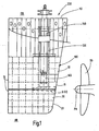
- the rudder 200 according to the invention for ships consists of two functionally co-operating components, namely a preferably full-rake rudder with a twisted rudder blade 100 and a rudder shaft 140 mounted in its upper region (FIG. Fig. 1 . 2 . 3 . 7 and 14 ).
- rudder 200 shown is 110 with a hull, with 120 a Kokerrohr for receiving the rudder stock 140 and 100 denotes the rudder blade.
- the rudder blade 100 is assigned a propeller 115.
- the propeller axis is designated PA.
- the rudder blade 100 according to Fig. 1 . 2 . 3 and 7 consists of two superposed rudder blade sections 10, 20, the nose strip 11 of the upper rudder blade section 10 are offset to port BB and the nose strip 21 of the lower rudder blade section 20 to starboard side SB to the longitudinal centerline LML of the Rudder blade 100 offset ( Fig. 4, 4A, 4B, 4C ; 4D, 4E and 13 ).
- the lateral displacement of the nose strips 11, 21 can also be achieved so that the nose strip 11 of the upper rudder blade section 10 are offset to starboard SB and the nose strip 21 of the lower rudder blade section 20 to port BB.
- the two side wall surfaces 12, 13 of the upper rudder blade section 10 and the side wall surfaces 21, 23 of the lower rudder blade section 20 extend from the nose strips 11, 21 arcuately in the direction of an end bar 15 facing away from the propeller 115 with the interposition of rectilinear side wall sections 16, 17 and 26, 27, which open into the end bar 15.
- the two rudder blade sections 10, 20 have an end bar 15 in common, whereas each rudder blade section 10, 20 has a nose strip 11 and 21, by the lateral dislocations, the twist is achieved.
- the rudder 200 preferably comprises a full-hovering rudder, but differently constructed rudders may also be used, as far as these are suitable for equipping with a twisted rudder blade and the advantages of the rudder blade design according to the invention are achieved.
- the two rudder blade sections 10, 20 arranged one above the other have equal or unequal heights.
- the lower rudder blade section 20 has a small height relative to the height of the upper rudder blade section, the height of the upper rudder blade section 10 being at least equal to 11 ⁇ 2 times the height of the lower rudder blade section 20.
- the nose strips 11, 21 of the two rudder blade sections 10, 20 are semicircular arc-shaped.
- the rudder blade 100 has tapered downwardly extending nose strips 11, 21, whereas the end rail 15 formed by the two rudder blade sections 10, 20 extends in a straight line and parallel to the rudder shaft 140 (FIG. Fig. 1 . 2 and 3 ).
- the conical shape of the nose strips 11, 21 of the two rudder blade sections 10, 20 is such that the size of the cross-sectional surfaces 30 of the two rudder blade sections 10, 20 at the same profile design of the upper rudder blade section 10 and the same profile design of the lower rudder blade section 20 from the upper area to OB decreasing the cross-sectional areas 30, a downwardly extending slim profile with a low profile thickness in the lower region, in particular by the course of the side wall surfaces 12, 13 and 22, 23 of the two rudder blade sections 10, 20 is obtained.
- the small profile thickness of the rudder blade 100 is an essential feature of the invention.
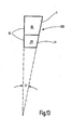
- Fig. 13 shows, the propeller 115 facing edge or nose strip 11, 21 of the rudder blade 100 of the propeller facing away edge or end bar 15 at an angle ⁇ of at least 5 °, preferably 10 °, sloping.
- the lengths L, L1 of the cross-sectional surface portions 31, 32 of the two rudder blade sections 10, 20 on both sides of the largest profile thickness PD are designed differently.
- the cross-sectional surface portions 31 of the upper rudder blade portion 20 and the lower rudder blade portion 20 in the area between the end bar 15 and the largest profile thickness PD of the rudder blade 100 have opposite the length L1 of the cross-sectional surface portions 32 of the upper rudder blade portion 10 and the lower rudder blade portion 20 between the largest profile thickness PD of the rudder blade 100 and the nose strips 11, 21 a greater length L on.
- the aspect ratio is preferably 11 ⁇ 2 times the length L compared to the length L1 (FIG. Fig. 5 ).
- the design of the rudder blade is such that the upper rudder blade portion 10 on the port side BB and the lower rudder blade portion 20 starboard side SB each have a flat arcuate and extending from the nose strips 11, 21 in the direction of the end bar 15 side wall portions 18, 28 having a length L2 corresponding to the length L'2 of the side wall portion 18 of the nose strips 11, 21 to the largest profile thickness PD plus a length L "2, which corresponds at least to the length L'2, wherein the flat arcuate side wall portion 28 of the rectilinear Side wall portion 16 connects, which terminates in the end bar 15 ( Fig. 5 ).
- the upper rudder blade portion 10 on the starboard side SB and the lower rudder blade portion 20 port side BB depending on a strongly curved, arcuate and extending from the nose strips 11, 21 toward the end bar 15 side wall portions 19, 29 with a length L3, the Length L'3 of the side wall portion 19 of the nose strips 11, 21 to the largest profile thickness PD plus one Length L "corresponds to 3, which corresponds at least to the length of L.
- the nose strip 11 of the upper rudder blade section 10 and the nose strip 21 of the lower rudder blade section 20 to port BB and starboard SB are laterally offset from the longitudinal center line LML such that the center line M2 drawn through the laterally offset nose strip sections is at an angle ⁇ of at least 3 ° to 10 ° °, but also higher, preferably 8 °, to the longitudinal center line LML of the cross-sectional area of a rib running.
- the rudder 200 further comprises a rudder stock 140 functionally cooperating with the rudder blade 100, in particular forged steel or another suitable material, which is mounted in a coker tube 120, in particular made of forged steel or another suitable material, by means of at least one bearing 150.
- the rudder stock 140 is located in the region of the largest profile thickness PD of the upper rudder blade section 10 and only in this ( Fig. 1 . 2 . 3 and 15 ), ie at the intersection of the line which represents the greatest profile thickness PD and the longitudinal center line LML (FIG. Fig. 5 ).
- the rudder stock 140 extends together with its attachment device 145 over the entire height of the upper rudder blade portion 10 of the rudder blade 100.
- the Kokerrohr 120 with the rudder stock 140 may also be arranged for design reasons in the upper rudder blade section 10 between the largest profile thickness PD and the nose strips 11, 21 ,
- the deep drawn into the upper rudder blade section 10 Kokerrohr 120 is provided as a cantilever with an inner bore 125 for receiving the rudder stock 140 ( Fig. 14 ).
- the arrangement of the Kokerrohres 120 takes place by inserting the Kokerrohres in accordance with the outer diameter of the Kokerrohres sized openings 105 in the frames 40 of the upper rudder blade section 10 (FIG. Fig. 3 . 8, 8A, 8B, 8C ).
- the Kokerrohr 120 is provided as a cantilever with a central inner longitudinal bore 125 for receiving the rudder stock 140 for the rudder blade 100.
- the Kokerrohr 120 is up to the rudder end connected to the rudder blade 100 extends only reaching into the upper rudder blade section 10.
- the bearing 150 for supporting the rudder stock 140 In its inner bore 125, the Kokerrohr 120, the bearing 150 for supporting the rudder stock 140, wherein preferably this bearing 150 is disposed in the lower end portion 120 b of the Kokerrohres 120.
- the rudder stock 140 is led out with its end 140b with a portion 145 of the Kokerrohr 120.
- this extended portion 145 of the rudder stock 140 is fixedly connected to the upper rudder blade portion 10 at 170, but here, too, a connection is provided which allows release of the rudder blade 100 of the rudder stock 140 when z. B. the propeller shaft to be replaced.
- connection of the rudder stock 140 in the area 170 with the twisted rudder blade 100 is above the propeller axis PA, so that for the expansion of the propeller shaft only the rudder blade 100 must be removed from the rudder stock 140, so that pulling out the rudder stock 140 from the Kokerrohr 120th is not required for a propeller shaft replacement, since both the free lower end 120b of the Kokerrohres and the free lower end of the rudder stock 140 are above the propeller shaft center.
- a single bottom bracket 150 for the storage of the rudder stock 140 in the Kokerrohr 120 provided; another bearing for the rudder blade 100 on the outer wall of the Kokerrohres 120 can be omitted.
- the rudder blade 100 For receiving the free lower end 120b of the Kokerrohres 120, the rudder blade 100 is provided with an indicated at 160 collection or recess.
- the cross section of the Kokerrohres 120 is designed thin-walled, which has at least one neck bearing 130 in the region of its free end for supporting the rudder stock 140 on the inner wall side. Also at other locations of Kokerrohres 120 additional bearings may be provided for the rudder stock.
- the rudder stock 140 is led out of the Kokerrohr 120 in its end region 140b with a portion 140a and connected to the upper rudder blade portion 10 with the end of this portion 140a ( Fig. 14 ).
- the upper rudder blade section 10 and the lower rudder blade section 20 consist of a rudder plating forming the side walls and of horizontal web plates or ribs 40, 50 and of vertical web plates or ribs which form the inner reinforcement of the two rudder blades.
- the web plates are provided with relief and water holes.
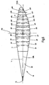
- FIG. 3 . 4, 4A, 4B . 4C and 8, 8A, 8B, 8C show all frames 40 of the upper rudder blade portion 10 of the rudder blade 100 same shape, same sidewall guide and matching nose strips 11 and end strips 15, wherein the length of the frames from the uppermost bulkhead to the lowest bulkhead and thus the size of the cross-sectional areas of the frames of decreases downwards so that the nose strips 11 to the bottom of the rudder blade 100 are inclined ( Fig. 1 ).
- All frames 50 of the lower rudder blade section 20 have the same shape, the same side wall guide and matching nose strips 21 and end strips 15, wherein the length of the frames 50 decreases from the uppermost bulkhead to the lowest bulkhead and thus the size of the cross-sectional areas of the ribs from top to bottom in that the nose strips 11 are inclined to the bottom of the lower rudder blade section 20.
- the two rudder blade sections 10, 20 can be directly connected to each other. Both Fig. 7 and 11 the two rudder blade sections 10, 20 are connected to one another via a fastening plate 45.
- This mounting plate 45 has symmetrical cross-sectional surface portions 46, 47 on both sides of the longitudinal center line LML and a surface profile and dimensions, including the bottom plate 42 of the upper rudder blade portion 10 and the cover plate 41 of the lower rudder blade portion 20 with their profiles and dimensions, so that when Aufzenetzen of the upper rudder blade profile 10 on the mounting plate 45 and when attaching the lower rudder blade portion 20 from below to the mounting plate 45 projects laterally with a very small edge region of the juxtaposed rudder blade sections 10, 20 ( 10 and 11 ).
- the fastening plate 45 has a semicircular edge rounding 11 'facing the propeller facing the longitudinal center line LML and an edge 15' facing away from the propeller, which merges into the end strips 15 of the two rudder blade sections 10, 20.
- the side wall surfaces 45a, 45b of the mounting plate 45 have matching curves.
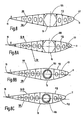
- the lower rudder blade section 20 whose frames 50 have a cross-sectional surface shape and shape, which correspond to those of the frames 40, but at 90 ° rotated about its longitudinal centerline LML frame 40 (FIG. Fig. 4D, 4E . 8D, 8E, 8F ).
- the ribs 40 of sections A, B, C and D are the same in profile but the cross-sectional area of the individual ribs 40 decreases from top to bottom so that the nose bar 11 is skewed.
- the section D connects to the mounting plate 45 at.
- the frames 50 of the sections E, F and G of the lower rudder blade section 20 have the same profile with the profiles of the frames 40, however, the side walls are with the strongly curved arcuate side wall portions 29 of the frames 50 port side BB ( Figs. 8D, 8E and 8F ), whereas in the embodiment Fig.
- the side walls of the ribs 40 with the strongly curved arcuate side wall portions 19 starboard side SB lie ( Figs. 8, 8A, 8B and 8C ).
- the cross-sectional areas of the ribs 50 of the lower rudder blade section 20 decrease in their length from top to bottom, so that the nose strip 21 of the lower rudder blade section 20 is also inclined ( Fig. 7 ).
- Fig. 9 the upper cover plate 43 of the upper rudder blade section 10 is shown, which is provided with the opening 105 for the insertion of the Kokerrohres 120.
- Fig. 10 shows a bottom view of the rudder blade 100 with its two rudder blade sections 10, 20 and the frames 40 and 50th
- the diameter of the opening 105 or bore in the upper rudder blade section 10 for receiving the Kokerrohres 120 for the rudder stock 140 is slightly smaller than the largest profile thickness PD of the rudder blade section 10. Due to this configuration, a very slim rudder blade profile is created.
- the configuration and the cross-sectional profile of the rudder blade 100 with its two rudder blade sections 10, 20 are such that the arcuate arcuate side wall sections 18, 28 of the upper and lower rudder blade sections 10, 20 have a short length L2, L'2 opposite the length L3 of the strongly curved arcuate side wall portions 19, 29 of the upper and lower rudder blade portions 10, 20 have ( Fig. 5 and 6 ).
- the distance ⁇ from the side wall portion 18 of the upper rudder blade portion 10 to the longitudinal centerline LML and the distance ⁇ 1 from the side wall portion 19 are the same. Up to the end bar 15, the distances ⁇ , ⁇ 1 are always the same size, but they decrease in relation to the end bar 15 from. In the direction of the leading edge 11, the following spacing conditions result: ⁇ ⁇ 2 ⁇ ⁇ ⁇ 3 ⁇ ⁇ 4 ⁇ ⁇ ⁇ 5 ⁇ ⁇ 6 ⁇ ⁇ 7
- This cross-sectional profile with the distances shown extends through all cross-sections of the upper rudder blade section 10 and through all cross-sections of the lower rudder blade, since all cross-sectional areas of the upper rudder blade section 10 have the same shapes, which also applies to the cross-sectional area of the lower rudder blade section 20, taking into account The fact that the cross-sectional area or ribs of the rudder blade 100 are tapered from top to bottom with respect to their lengths and with respect to their areas facing the leading edge ( Fig. 10 ).
- the arc length BL1 of the highly curved arcuate side wall sections 19, 29 of the upper and lower rudder blade sections 10, 20 is according to a further embodiment according to Fig. 14 greater than the arc length BL of the arcuate arcuate side wall portions 18, 28 of the upper and lower rudder blade portions 10, 20 so that the transition areas ÜB1 of the strongly curved arcuate side wall portions 19, 29 of the upper and lower rudder blade portions 10, 20 are rectilinear to the End bar 15 extending side wall portions 17, 27 and the transition areas ÜB the flat arcuate side wall portions 18, 28 of the upper and lower rudder blade sections 10, 20 to the rectilinear to the end bar 15 extending side wall sections 16, 26 are offset in the direction of the end bar 15 such that the Transition area ÜB1 facing the transition area ÜB the end bar is facing.
- the lengths of the side wall sections 18, 19 and 28, 29 are as follows: L ⁇ 3 ⁇ L ⁇ 2 L' ⁇ 2 ⁇ L' ⁇ 3 L ⁇
- the legs of the rectilinear side wall portions 16, 17, 26, 27 of the upper rudder blade portion 10 and the lower rudder blade portion 20, which converge to the end bar 15, preferably have the same lengths, but also an unequal length design is possible.
- the invention also includes rudders in which the twisted rudder blade 100 is provided with a fin extending over the two rudder blade sections 10, 20.
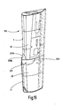
- FIG. 16 to 23 show in the transition region of the two laterally offset portions A1, A2 of the two superimposed rudder blade sections 10, 20 and that the arcuate course of the nose strips 11, 21 correspondingly shaped baffles 200, 201 (deflectors) with a streamlined, curved, elongated or hemispherical profile arranged, of which a guide plate 200 from the nose strip 11 of the upper rudder blade section 10 extends in the side wall and the other baffle 201 from the nose strip 21 of the lower rudder blade section 20 in the side wall and with their mutually facing lying edges (200d, 201 d) are connected to each other.
- the two baffles 200, 201 complement each other to form a flow body which covers the transition region between the offset regions of the two rudder blade sections 10, 20.
- Both the upper rudder blade section 10 and the lower rudder blade section 20 each have a strip-shaped and slightly curved baffle 200 or 201 adapted to the outer wall shape of the rudder blade, with each of the two baffles facing the nose strips 11, 21 and the propeller 115 Section 200b and 201 b is located in the region of the leading edge and part, that is an integral part of the leading edge.
- each baffle 200 or 201 is provided with a rear strip-shaped section 200 c or 201 c, which rests against the side wall of the rudder or is integrated into the latter ( Fig. 17 .
- the portions 200b and 201b of the two baffles 200, 201 are in the region of the nose strips 11, 21 and have approximately a cap-shaped configuration 200a, 201a, which have a roughly semicircular shape when viewed from the front on the nose strips 11, 21 ( Fig. 16 and 22 ), wherein these cap-shaped portions 200b, 201 b are offset to the port BB and starboard SB as the nose strips 11, 21 ( Figure 22 ).
- the two cap-shaped sections 200b, 201b together form two cone halves 200'b, 201'b which stand against one another with their base sides ( Fig. 16 . 17 . 20 ).
- the port side side wall of the upper rudder blade portion 10 the baffle 200 and the starboard side band of the lower rudder blade portion 20, the baffle 2001, wherein the baffles 200, 201 are arranged so that their strip-shaped and bead-shaped portions 200 c, 201 c in the Side walls of the rudder blade are, while their propeller 115 facing portions 200b, 201 b in the region of the nose strips 11, 21 are.
- a strömungsterrorismieris baffle 210 is provided which is hemispherical in shape.
- the rudder according to the invention is characterized by the features indicated in the claims, by the embodiments set forth in the description and by the embodiments illustrated in the figures of the drawings.
- the baffles 200, 201 and 210 arranged in the offset region of the two rudder blade sections 10, 20 have the embodiments described in the description and illustrated in the figures. and are also like the rudder blade design of the invention.
Abstract
Description
Die Erfindung betrifft ein Ruder für Schiffe mit höheren Geschwindigkeiten mit einem kavitationsreduzierenden, twistierten, insbesondere Vollschweberuder gemäß dem Oberbegriff des Anspruches 1.The invention relates to a rudder for ships at higher speeds with a cavitation-reducing, twisted, in particular full-swarm powder according to the preamble of
Schiffsruder, wie Vollschweberuder oder Balance-Profilruder, mit oder ohne angelenkter Flosse sind in den verschiedensten Ausführungsformen bekannt. Ebenso bekannt sind Schiffsruder mit einem twistierten Ruderblatt, das aus zwei übereinanderliegenden Ruderblattabschnitten besteht, deren dem Propeller zugekehrte Nasenleisten derart seitlich versetzt sind, dass die eine Nasenleiste nach Backbord und die andere Nasenleiste nach Steuerbord versetzt ist.Ship rudders, such as full-rudder or balance rudder, with or without hinged fin are known in various embodiments. Also known are ship's rudder with a twisted rudder blade, which consists of two superimposed rudder blade sections, the propeller facing nose strips are offset laterally such that one leading edge to port and the other nose strip is offset to starboard.
So beschreibt
Die
Auch die DE 20 2004 006 453 U1 beschreibt ein Ruder für Schiffe, das aus einem Ruderblatt und einem dem Ruder zugeordneten, auf einer antreibbaren Propellerachse angeordneten Propeller besteht, wobei das Ruderblatt zwei übereinander liegende Ruderblattabschnitte aufweist, deren dem Propeller zugekehrten vorderen Nasenleisten derart versetzt sind, dass die eine Nasenleiste nach Backbord oder Steuerbord und die andere Nasenleiste nach Steuerbord oder Backbord versetzt sind, wobei die beiden Seitenwandflächen des Ruderblattes in eine dem Propeller abgewandte Endleiste zusammenlaufen. Das den Ruderschaft aufnehmende Ruderkokerlager ist als Kragträger ausgebildet und mit einer mittigen Innenlängsbohrung zur Aufnahme des Ruderschaftes für das Ruderblatt versehen. Das Ruderkokerlager ist bis in das mit dem Ruderschaftende verbundene Ruderblatt hineinreichend ausgebildet, so dass der untere Ruderbiattsbschnitt des Ruders kein schmales Profil aufweist.DE 20 2004 006 453 U1 also describes a rudder for ships, which consists of a rudder blade and a rudder associated, arranged on a drivable propeller axis propeller, wherein the rudder blade has two superimposed rudder blade sections whose propeller facing front nose strips are so offset in that one leading edge is offset to port or starboard and the other leading edge to port or starboard, with the two side wall surfaces of the rudder blade converging into an end strip facing away from the propeller. The rudder stock receiving rudder rod bearing is designed as a cantilever and provided with a central inner longitudinal bore for receiving the rudder stock for the rudder blade. The rudder trunk bearing is formed reaching into the rudder blade connected to the rudder end, so that the lower rudder biaxial section of the rudder does not have a narrow profile.
Die Geschwindigkeiten moderner Schiffe nehmen immer weiter zu. Durch die mit der höheren Geschwindigkeit verbundenen schnellen Strömungsgeschwindigkeiten nimmt die Belastung auf die Propeller und auf das Ruder zu. Die Symmetrie des Profils von bekannten Ruderblättern führt zu Unterdruckgebieten auf der Ruderoberfläche, die zu Kavitationen und so zu Erosionen führen. Kavitation entsteht an den Stellen des Ruderblattes, an denen die Strömung extrem beschleunigt wird. Dabei schlägt die starke Rotationsströmung des Propellers mit großer Geschwindigkeit auf der Ruderblattoberfläche auf. Durch diese starke Beschleunigung sinkt der statische Druck unter den Dampfdruck des Wassers, wodurch Dampfblasen entstehen, die schlagartig implodieren. Diese Implosionen führen zu einer Zerstörung der Ruderblattoberfläche, was teure Reparaturen zur Folge hat; oftmals müssen neue Ruderblätter eingesetzt werden.The speeds of modern ships continue to increase. The faster velocities associated with the higher speed increase the load on the propellers and on the rudder. The symmetry of the profile of known rudder blades leads to negative pressure areas on the rudder surface, which lead to cavitations and thus to erosion. Cavitation occurs at the points of the rudder blade, where the flow is extremely accelerated. The strong rotational flow of the propeller beats at high speed on the rudder blade surface. Due to this strong acceleration, the static pressure drops below the vapor pressure of the water, creating vapor bubbles that implode abruptly. These implosions lead to the destruction of the rudder blade surface, resulting in costly repairs; Often new rudder blades must be used.
Es ist Aufgabe der vorliegenden Erfindung, ein Ruder für Schiffe mit große und sehr große Abmessungen aufweisenden, insbesondere Vollschweberuderblättern mit twistierter Rudervorderkante zu schaffen, bei denen Erosionserscheinungen am Ruderblatt durch Kavitationsbildung, insbesondere beim Einsatz bei schnellen Schiffen mit hochbelasteten Propellern, vermieden werden. Des Weiteren soll ein Ruderblatt eine geringe Profildicke und der untere Ruderblattabschnitt des Ruderblattes ein schmales Profil aufweisen. Außerdem sollen die auf das Ruderblatt in dessen unteren Bereich einwirkenden, durch den sehr hohe Strömungsgeschwindigkeiten aufweisenden Propellerabstrom erzeugten Kräfte aufgefangen und das Ruderblatt ausbalanciert werden, ohne dass dabei eine Beschädigung der Lager für den Ruderschaft eintritt.It is an object of the present invention to provide a rudder for ships with large and very large dimensions, in particular Vollschweberuters leaves twisted rudder leading edge, in which erosion phenomena At the rudder blade cavitation formation, especially when used in fast ships with highly loaded propellers, avoided. Furthermore, a rudder blade should have a small profile thickness and the lower rudder blade portion of the rudder blade a narrow profile. In addition, the generated on the rudder blade in the lower region, generated by the very high flow velocities Propellerabstrom forces are collected and the rudder blade are balanced, without causing damage to the bearings for the rudder stock.
Gelöst wird diese Aufgabe bei einem Ruder gemäß der eingangs beschriebenen Art mit den im Anspruch 1 angegebenen Merkmalen.This object is achieved in a rudder according to the type described above with the features specified in
Hiernach ist das erfindungsgemäße Ruder dadurch gekennzeichnet, dass es
- a.) aus einem ein schlankes Profil mit einer geringen Profildicke aufweisenden, bevorzugterweise Vollschweberuderblatt aus zwei übereinanderliegend angeordneten Ruderblattabschnitten mit gleichen oder ungleichen Höhen, bevorzugterweise mit einem eine gegenüber der Höhe des oberen Ruderblattabschnittes eine geringere Höhe aufweisenden unteren Ruderblattabschnitt und mit dem Propeller zugekehrten, ein in etwa halbkreisförmiges Profil aufweisenden Nasenleisten besteht, die derart positioniert sind, dass die eine Nasenleiste nach Backbord BB oder Steuerbord SB und die andere Nasenleiste nach Steuerbord SB oder Backbord BB seitlich zur Längsmittellinie LML des Ruderblattes versetzt sind, wobei die Seitenwandflächen der beiden Ruderblattabschnitte in eine dem Propeller abgewandte Endleiste zusammenlaufen,
- a1.) wobei die beiden Nasenleisten und die Endleiste unter Verringerung der Querschnittsflächen vom oberen Bereich OB zum unteren Bereich UB des Ruderblattes konisch sich nach unten verjüngend verlaufen,
- a2.) oder die Endleiste geradlinig und parallel zum Ruderschaft verläuft und die beiden Nasenleisten unter Verringerung der Größe der Querschnittsflächen vom oberen Bereich OB zum unteren Bereich UB des Ruderblattes konisch sich nach unten verjüngend verlaufen,
- a3.) wobei die Querschnittsflächenabschnitte des oberen Ruderblattabschnittes und des unteren Ruderblattabschnittes im Bereich zwischen der Endleiste und der größten Profildicke PD des Ruderblattes eine Länge L aufweisen, die mindestens dem 1 ½-Fachen gegenüber der Länge L1 der Querschnittsflächenabschnitte des oberen Ruderblattabschnittes und des unteren Ruderblattabschnittes zwischen der größten Profildicke PD des Ruderblattes und den Nasenleisten entsprechen,
- a4.) wobei der obere Ruderblattabschnitt backbordseitig BB und der untere Ruderblattabschnitt steuerbordseitig SB je einen flach bogenförmig verlaufenden und sich von den Nasenleisten in Richtung zu der Endleiste erstreckenden Seitenwandabschnitt mit einer Länge L2 erstrecken, die sich über die Länge L'2 der Seitenwandabschnitte von den Nasenleisten bis zur größten Profildicke PD zuzüglich einer Länge L"2 erstreckt, die mindestens der Länge L'2 entspricht, wobei sich an den flach bogenförmig verlaufenden Seitenwandabschnitt der geradlinig verlaufende Seitenwandabschnitt anschließt, der in die Endleiste ausläuft,
- a5.) wobei der obere Ruderblattabschnitt steuerbordseitig SB und der untere Ruderblattabschnitt backbordseitig BB je einen stark gewölbt bogenförmig verlaufenden und sich von den Nasenleisten in Richtung zu der Endleiste erstreckenden Seitenwandabschnitt mit einer Länge L3 aufweisen, die sich über die Länge L'3 der Seitenwandabschnitte von den Nasenleisten bis zur größten Profildicke PD zuzüglich einer Länge L"3 erstreckt, die mindestens der Länge L'3 entspricht, wobei sich an den stark gewölbt verlaufenden bogenförmigen Seitenwandabschnitt ein geradlinig verlaufender Seitenwandabschnitt anschließt, der in die Endleiste ausläuft,
- a6.) wobei die beiden geradlinig verlaufenden Seitenwandabschnitte paarweise gleiche Längen aufweisen und die zwischen den beiden Seitenwandabschnitten liegenden Querschnittsflächenabschnitte gleich groß und symmetrisch ausgebildet sind, und
- a7.) wobei der Abstand zwischen dem flach bogenförmig verlaufenden Seitenwandabschnitt zur Längsmittellinie LML gegenüber dem Abstand zwischen dem stark bogenförmig verlaufenden Seitenwandabschnitt zur Längsmittellinie LML größer ist und die zwischen den beiden bogenförmig verlaufenden Seitenwandabschnitten zu beiden Seiten der Längsmittellinie LML liegenden Querschnittsflächenabschnitte asymmetrisch ausgebildet sind und
- a8.) der Ruderschaft im Bereich der größten Profildicke im oberen Ruderblattabschnitt des Ruderblattes oder zwischen der größten Profildicke und der Nasenleiste des oberen Ruderblattabschnittes in diesem angeordnet ist, und sich mit seiner endseitigen Befestigungsvorrichtung über die gesamte Höhe des oberen Ruderblattabschnittes erstreckt, so dass der untere Ruderblattabschnitt ein schmales Profil aufweist.
- a.) From a slender profile with a small profile thickness having, preferably Vollschweberutersblatt of two superimposed arranged rudder blade sections with the same or unequal heights, preferably with a comparison with the height of the upper rudder blade portion a lower height having lower rudder blade portion and facing the propeller, a in approximately semicircular profile having leading edges, which are positioned so that one leading edge to port BB or starboard SB and the other leading edge bar SB or port BB are offset laterally to the longitudinal center line LML of the rudder blade, the side wall surfaces of the two rudder blade sections in a converging end bar facing away from the propeller,
- a1.) wherein the two nose strips and the end strip taper conically downwards, reducing the cross-sectional areas from the upper region OB to the lower region UB of the rudder blade,
- a2.) or the end bar is rectilinear and parallel to the rudder stock, and the two leading ridges taper conically downward from the upper area OB to the lower area UB of the rudder blade, reducing the size of the cross-sectional areas.
- a3.) wherein the cross-sectional surface portions of the upper rudder blade portion and the lower rudder blade portion in the region between the end bar and the largest profile thickness PD of the rudder blade have a length L which is at least 1 ½ times the length L1 of the cross-sectional surface portions of the upper rudder blade portion and the lower rudder blade portion between the largest profile thickness PD of the rudder blade and the leading edge,
- a4). The upper rudder blade portion on the port side BB and the lower rudder blade portion on the starboard side SB each extend a flat arcuate and extending from the nose strips towards the end strip side wall portion with a length L2 extending over the
length L 2 of the side wall portions of the Nose strip extends to the largest profile thickness PD plus a length L "2, which corresponds at least to the length L'2, wherein adjoining the flat arcuate side wall portion of the rectilinear side wall portion which terminates in the end bar, - a5.) wherein the upper rudder blade portion starboard side SB and the lower rudder blade portion port BB each have a strongly curved arcuate extending from the nose strips towards the end bar side wall portion having a length L3 extending over the length L'3 of the side wall portions of extends the nose strips to the largest profile thickness PD plus a length L "3, which corresponds at least to the length of L'3, wherein the strongly arched extending arcuate side wall portion is followed by a rectilinear side wall portion which terminates in the end bar,
- a6.) Wherein the two rectilinear side wall sections have pairs of equal lengths and lying between the two side wall sections cross-sectional surface portions are formed equal and symmetrical, and
- a7.) wherein the distance between the flat arcuate side wall portion to the longitudinal centerline LML compared to the distance between the highly arcuate side wall portion to the longitudinal centerline LML is greater and lying between the two arcuate side wall portions on both sides of the longitudinal centerline LML cross-sectional surface portions are formed asymmetrically and
- a8.) of the rudder stock in the region of the largest profile thickness in the upper rudder blade section of the rudder blade or between the largest profile thickness and the nose strip of the upper rudder blade section is arranged therein, and extends with its end-side fastening device over the entire height of the upper rudder blade section, so that the lower Ruderblattabschnitt has a narrow profile.
Überraschend hat es sich gezeigt, dass durch die erfindungsgemäße Ausgestaltung des twistierten Ruderblattes als Vollschweberuder mit seiner geringen Profildicke und der Lagerung des Ruderschaftes im Bereich der größten Profildicke im oberen Ruderblattabschnitt des Ruderblattes der untere Ruderblattabschnitt ein schmales Profil erhält, so dass trotz der hohen Geschwindigkeiten des auf das Ruderblatt auftreffenden Propellerabstromes ohne zusätzlichen Kräfteaufwand ein Ausbalancieren des Ruderblattes, auch wenn dieses größte Abmessungen aufweist, möglich ist, was nur durch das funktionale Zusammenwirken von twistiertem Ruderblatt mit der Ruderblattlagerung erreichbar ist, was aber nicht erreicht werden kann bei anderen Ruderblattausgestaltungen und Ruderschaftlagerungen.Surprisingly, it has been shown that the lower rudder blade section is given a narrow profile by the inventive design of the twisted rudder blade as Vollschweberuder with its low profile thickness and the storage of the rudder stock in the region of the largest profile thickness in the upper rudder blade section of the rudder blade, so that despite the high speeds of counterbalancing the rudder blade, even if it has the largest dimensions, is possible without additional effort on the rudder blade impacting which can only be achieved by the functional interaction of twisted rudder blade with the rudder blade bearing, but this can not be achieved with other rudder blade configurations and rudder stock bearings.
Mit der Erfindung wird ein Ruder mit einem twistierten Ruderblatt geschaffen. Dieses Ruder ist die überraschend aufgefundene technische Lösung, um große und größte Vollschweberuderblätter zu bauen. Das tief in den oberen Ruderblattabschnitt des Ruderblattes hineingezogene Kokerrohr mit dem Ruderschaft leitet über das im unteren Bereich des oberen Ruderblattabschnittes integrierte Halslager die Ruderkräfte auf direktem Wege in den Schiffskörper ein. Die Krafteinleitung geschieht als Kragarm, also als reine Biegebeanspruchung, ohne Torsionsmomente. Dadurch kann der Kokerrohrquerschnitt verhältnismäßig dünnwandig ausgeführt werden. Diese Dünnwandigkeit ist sehr wichtig, da der untere Teil des Kokerrohres im Ruderblatt, d. h. im oberen Ruderblattabschnitt, untergebracht ist und somit direkten Einfluss auf die Profildicke des Ruderblattes hat. Nur ein schlankes Ruderprofil, also eine geringe Profildicke, ermöglicht überhaupt den Bau energieeffizienter Ruderblätter, denn je dicker ein Ruderprofil ist, desto mehr Widerstand erzeugt es in der beschleunigten Strömung des Propellerwassers.The invention provides a rudder with a twisted rudder blade. This rudder is the surprisingly found technical solution to build big and largest full-swede-leafs. The deep drawn into the upper rudder blade portion of the rudder blade Kokerrohr with the rudder shaft passes over the integrated in the lower part of the upper rudder blade section neck rudder forces directly into the hull. The force is applied as a cantilever, so as pure bending stress, without torsional moments. As a result, the Kokerrohrquerschnitt can be made relatively thin-walled. This thinness is very important because the lower part of the Kokerrohres in the rudder blade, ie in the upper rudder blade section, housed and thus has a direct influence on the profile thickness of the rudder blade. Only a slim rudder profile, so a low profile thickness, allows the construction of energy efficient rudder blades, because the thicker a rudder profile, the more resistance it generates in the accelerated flow of the propeller water.
Ein weiterer, wesentlicher Vorteil des Ruders ist der, dass durch diese Art der in das Ruderblatt, d. h. in den oberen Ruderblattabschnitt integrierten Lagerung erst die Bauart des Vollschweberuders oder Spatenruders ermöglicht wird und das noch in nahezu unbegrenzter Größe. Konventionelle Ruder sind Halbschweberuder mit einem Ruderhorn oder Ruderträger. Solche schwierigen mechanischen Konstruktionen lassen sich kaum an der Vorderkante twistieren, da das feststehende Ruderhorn und das darum drehende Ruderblatt nicht so frei formbar sind. Die bei solchen Halbschweberudern auftretenden ruderblattintemen Kräfte und Momente sind ungleich größer als bei Vollschweberudern mit der erfindungsgemäßen Lagerung des Ruderschaftes. Eine nennenswerte Twistierung der dem Propeller zugekehrten Vorderkante des Ruderblattes würde erhebliche konstruktive unwirtschaftliche Maßnahmen bedeuten, nämlich mit entsprechend dickeren Profilen.Another significant advantage of the rudder is that by this type of rudder blade, d. H. in the upper rudder blade section integrated storage only the design of the Vollschweberuders or spade rudder is enabled and still in almost unlimited size. Conventional oars are Halbschweberuder with a rudder horn or Ruderträger. Such difficult mechanical constructions can hardly be twisted at the front edge, since the fixed rudder horn and the rotating rudder blade are not so freely formable. The rudder blade forces and moments occurring in such half-rudder thrusters are much larger than in full-rudder thrusters with the rudder stock bearing according to the invention. A significant twisting of the propeller-facing front edge of the rudder blade would mean significant constructive uneconomic measures, namely with correspondingly thicker profiles.
Noch ein Vorteil besteht darin, dass durch die Lagerung des Ruderschaftes erst Vollschweberuder als Bauform möglich werden, was bedeutet, dass keine Spalten mehr zwischen den bisher nötigen Ruderhörnern und deren Ruderblättern existieren. Dadurch wird die Querströmung durch diese Spalte vermieden und die dazu gehörigen schweren Kavitationserosionen ebenfalls.Another advantage is that the storage of the rudder stock only Vollschweberuder be possible as a design, which means that there are no more gaps between the previously required rudder horns and their rudder blades. This avoids cross-flow through these gaps and the associated heavy cavitation erosions as well.
Hinzu kommt, dass bei der erfindungsgemäßen Ausgestaltung des Ruders der bevorzugterweise aus Schmiedestahl bestehende Ruderkoker in das Ruderblatt, d. h. in den oberen Ruderblattabschnitt, hinein verlängert ist, jedoch nur mit einem unteren Halslager. Der Ruderschaft, ebenfalls mit einem Schmiedestück als Nabe, ist nahe dem hydrodynamischen Zentrum mit dem Ruder verbunden, wodurch eine nur geringe Belastung durch Biegemomente erzielt wird. Sich überlagernde Vibrationen können durch diese Ausgestaltung ausgeschlossen werden.In addition, in the inventive design of the rudder, preferably consisting of forged steel rudder in the rudder blade, d. H. extended into the upper rudder blade section, but only with a lower neck bearing. The rudder stock, also with a forging as a hub, is connected to the rudder near the hydrodynamic center, whereby only a small load is achieved by bending moments. Overlapping vibrations can be excluded by this design.
Durch das schlanke Ruderprofil und somit durch die geringe Profildicke des Ruderblattes ist es möglich, das Ruderblatt ohne besondere Beanspruchung des Lagers für den Ruderschaft, gegenüber dem hohen Druck des mit sehr hoher Geschwindigkeit auf den unteren Ruderblattabschnitt auftreffenden Propellerabstroms auszubalancieren.Due to the slim rudder profile and thus by the small profile thickness of the rudder blade, it is possible to balance the rudder blade without special stress of the bearing for the rudder stock, against the high pressure of the striking at very high speed on the lower rudder blade section propeller effluent.
Um die Kavitation am Ruderblatt zu eliminieren, weist dieses das erfindungsgemäße Profil auf, das in eine Ober- und Unterhälfte geteilt ist, deren Nasenleisten bzw. Anströmkanten in bestimmten Winkeln vertwistet sind. Die Propellernachlaufströmung und der Winkel dieser zur Mittschiffslinie gibt vor, um wie viel Grad die Profilvorderkante verdreht ist. Durch diese neue Profilvariante fließt die Propellerwirbelströmung besser am Ruderblatt entlang, und es entstehen keine Druckspitzen auf der Profiloberfläche des Ruderblattes, die die Kavitation begünstigen. Die verbesserte Umströmung des Ruders führt zu erheblichen Kraftstoffeinsparungen und zu einer verbesserten Manövrierbarkeit.To eliminate the cavitation on the rudder blade, this has the profile according to the invention, which is divided into an upper and lower half, the leading edge or leading edges are vertwistet at certain angles. The propeller tracking flow and the angle of this to the midship line dictate how many degrees the profile leading edge is twisted. With this new profile variant, the propeller vortex flow flows better along the rudder blade, and there are no pressure peaks on the tread surface of the rudder blade, which favor cavitation. The improved flow around the rudder results in significant fuel savings and improved maneuverability.
Vorteilhafte Ausgestaltungen der Erfindung sind Gegenstand der Unteransprüche.Advantageous embodiments of the invention are the subject of the dependent claims.
Eine weitere vorteilhafte Ausgestaltung der Erfindung besteht darin, dass der twistierte Bereich des Ruderblattes geschlossene Übergänge aufweist. Hierzu sind im Übergangsbereich der beiden seitlich versetzten Abschnitte der beiden übereinanderliegend angeordneten Ruderblattabschnitte dem bogenförmigen Verlauf der Nasenleisten entsprechend geformte Strömungskörper bildende, den Versatzbereich abdeckende Leitbleche mit einem strömungsgünstigen, gewölbten und der Außenwand des Ruderblattes angepassten, länglichen oder halbkugelförmigen Profil angeordnet, von denen sich ein Leitblech von der Nasenleiste des oberen Ruderblattabschnittes bis in dessen Seitenwand und das andere Leitblech von der Nasenleiste des unteren Ruderblattabschnittes bis in dessen Seitenwand erstreckt.A further advantageous embodiment of the invention is that the twisted region of the rudder blade has closed transitions. For this purpose, in the transition region of the two laterally offset portions of the two superposed rudder blade sections the arcuate course of the nose strips correspondingly shaped flow body forming, the offset area covering baffles arranged with a streamlined, curved and the outer wall of the rudder blade, elongated or hemispherical profile, of which a Guide plate from the nose strip of the upper rudder blade section extends in the side wall and the other baffle from the nose strip of the lower rudder blade section to the side wall.
Durch die Anordnung von Leitblechen in den Übergangsbereichen der versetzten Abschnitte der beiden übereinanderliegend angeordneten Ruderblattabschnitte wird ein strömungsgünstiges Profil geschaffen, wodurch gerade in diesen Übergangsbereichen sonst auftretende Kavitationen vermieden werden. Die strömungskörperartig ausgebildeten "Leitbleche" sind dabei derart ausgebildet, dass sie den Übergangsbereich zwischen den beiden Nasenleisten abdecken. Die Leitbleche liegen also im Bereich der Versatzbereiche am Ruderblatt an und decken diese ab, so dass das Wasser anstatt an den Versatzbereichen an den Leitblechen entlangströmt. Dadurch wird die Gefahr einer Strömungsverwirbelung gesenkt. Die Leitbleche bzw. deren Wanderungen bilden somit eine seitliche Überbrückung bzw. Abdeckung des Übergangsbereiches zwischen dem oberen und dem unteren Ruderblattabschnitt. Der Begriff "Abdecken" ist vorliegend derart zu verstehen, dass die Leitbleche der Strömungskörper den Versatzbereich weitestgehend abdeckt.The arrangement of baffles in the transition regions of the offset portions of the two superimposed rudder blade sections creates a flow-favorable profile, which avoids otherwise occurring cavitations in these transition areas. The Strömungskörperartig formed "baffles" are designed such that they cover the transition region between the two nose strips. The guide plates thus lie in the region of the offset regions on the rudder blade and cover them, so that the water flows along the guide plates instead of at the offset regions. This reduces the risk of flow turbulence. The baffles or their migrations thus form a lateral bridging or covering the transition region between the upper and lower rudder blade section. The term "covering" is to be understood in the present case such that the baffles of the flow body largely covers the offset region.
Vorteilhaft bei einem derart erfindungsgemäß ausgebildeten Ruder mit einem twistierten Ruderblatt ist, dass durch die nur lokal im Versatzbereich ausgebildeten bzw. angeordneten, die Versatzflächen abdeckenden und sich zu einem Strömungskörper ergänzenden Leitbleche die Gefahr des Abreißens der Strömung vermindert werden kann, wobei die strömungskörperartigen Leitbleche gleichzeitig durch die relativ geringen Abmessungen keinen Einfluss auf das Propulsionsverhalten des Schiffes nimmt. Hierdurch stellt sich ein "propulsionsneutraler Effekt" ein.An advantage of a rudder designed in accordance with the invention with a twisted rudder blade is that the danger of the flow being torn off can be reduced by the baffles covering the offset surfaces and supplementing the flow surfaces with the baffles only due to the relatively small dimensions it does not influence the propulsion behavior of the ship. This creates a "propulsion-neutral effect".
Das Ruder weist ferner einen mit dem Ruderblatt funktional zusammenwirkenden Ruderschaft mit mindestens einem Lager auf,
wobei der Ruderschaft, insbesondere aus Schmiedestahl oder einem anderen geeigneten Material zusammen mit dem diesen aufnehmenden Kokerrohr, insbesondere aus Schmiedestahl oder einem anderen geeigneten Material im Bereich der größten Profildicke PD oder zwischen dieser und den Nasenleisten des oberen Ruderblattabschnittes in diesem angeordnet ist und sich mit seiner endseitigen Befestigungsvorrichtung über die gesamte Höhe des oberen Ruderblattabschnittes erstreckt, und
wobei das tief in den oberen Ruderblattabschnitt hineingezogene Kokerrohr für den Ruderschaft als Kragarm mit einer mittigen Innenlängsbohrung zur Aufnahme des Ruderschaftes versehen ist, und
wobei der Kokerrohrquerschnitt dünnwandig ausgeführt ist und das Kokerrohr bevorzugterweise im Bereich seines freien Endes zur Lagerung des Ruderschaftes innenwandseitig ein Halslager aufweist, und
wobei der Ruderschaft in seinem Endbereich mit einem Abschnitt aus dem Kokerrohr herausgeführt und mit dem Ende dieses Abschnittes mit dem oberen Ruderblattabschnitt verbunden ist.The rudder further includes a rudder post which cooperates functionally with the rudder blade and has at least one bearing,
wherein the rudder stock, in particular from forged steel or other suitable material together with this receiving Kokerrohr, in particular from wrought steel or other suitable material in the region of the largest profile thickness PD or between this and the nose strips of the upper rudder blade section is arranged in this and with his end fastening device extends over the entire height of the upper rudder blade section, and
wherein the deep drawn into the upper rudder blade portion Kokerrohr for the rudder stock is provided as a cantilever arm with a central inner longitudinal bore for receiving the rudder stock, and
wherein the Kokerrohrquerschnitt is designed thin-walled and the Kokerrohr preferably in the region of its free end for supporting the rudder stock on the inside wall side has a neck bearing, and
wherein the rudder stock is led out in its end region with a portion of the Kokerrohr and connected to the end of this section with the upper rudder blade section.
Ein weiterer Vorteil des Ruders der Kombination des twistierten Ruderblattes mit der Lagerung des Ruderschaftes ist der Einsatz von höherwertigen Materialien. Nur durch die erfindungsgemäße Lagerung des Ruderschaftes in dem oberen Ruderblattabschnitt kann hochfester Schmiedestahl so eingesetzt werden, dass eine wesentliche Gewichtsreduzierung zustande kommt und auch erreicht wird, d. h. bis zu 50 % des konventionellen Ruders gleicher Leistung.Another advantage of the rudder of the combination of the twisted rudder blade with the bearing of the rudder stock is the use of higher quality materials. Only by the inventive storage of the rudder stock in the upper rudder blade section can high-strength Forged steel can be used so that a significant weight reduction is achieved and is achieved, ie up to 50% of the conventional rudder of the same power.
So sieht die Erfindung ferner vor, dass zwischen dem oberen Ruderblattabschnitt und dem unteren Ruderblattabschnitt eine Befestigungsplatte angeordnet und mit den Ruderblattabschnitten fest verbunden ist, wobei die Befestigungsplatte symmetrische Querschnittsflächenabschnitte zu beiden Seiten der Längsmittellinie LML und ein Profil sowie Abmessungen aufweist, die die Bodenplatte des oberen Ruderblattabschnittes und die Deckplatte des unteren Ruderblattabschnittes mit ihren Profilen und Abmessungen mit einschließen.Thus, the invention further contemplates that a mounting plate is disposed between the upper rudder blade portion and the lower rudder blade portion and secured to the rudder blade portions, the mounting plate having symmetrical cross-sectional area portions on both sides of the longitudinal centerline LML and a profile and dimensions defining the bottom plate of the upper Include rudder blade section and the cover plate of the lower rudder blade section with their profiles and dimensions.
Eine weitere Ausgestaltung der Erfindung sieht vor, dass die Nasenleiste des oberen Ruderblattabschnittes und die Nasenleiste des unteren Ruderblattabschnittes nach Backbord BB und Steuerbord SB gegenüber der Längsmittellinie LML seitlich derart versetzt sind, dass die durch die seitlich versetzten Nasenleistenabschnitte gezogene Mittellinie M2 in einem Winkel α von mindestens 3° bis 10°, jedoch auch höher, bevorzugterweise 8°, zur Längsmittellinie LML der Querschnittsfläche eines Spants verlaufend ist.A further embodiment of the invention provides that the nose strip of the upper rudder blade section and the nose strip of the lower rudder blade portion are offset laterally to port BB and starboard SB with respect to the longitudinal center line LML such that the center line M2 drawn through the laterally offset nose strip sections at an angle α of at least 3 ° to 10 °, but also higher, preferably 8 °, to the longitudinal center line LML of the cross-sectional area of a rib running.
Des Weiteren ist eine erfindungsgemäße Ausgestaltung vorgesehen, die darin besteht, dass die backbordseitig BB und steuerbordseitig SB liegenden flach gewölbten, bogenförmigen Seitenwandabschnitte der oberen und unteren Ruderblattabschnitte eine kürzere Länge L4 gegenüber der Länge der steuerbordseitig SB und backbordseitig BB liegenden stark gewölbten bogenförmigen Seitenwandabschnitte der oberen und unteren Ruderblattabschnitte aufweisen.Furthermore, an embodiment of the invention is provided, which is that the port side BB and starboard SB lying flat arched side wall portions of the upper and lower rudder blade sections a shorter length L4 compared to the length of the starboard SB and port BB lying strongly arched arcuate side wall portions of the upper and lower rudder blade sections.
Die Erfindung sieht darüber hinaus auch noch vor, dass die Bogenlänge BL1 der stark gewölbten bogenförmigen Seitenwandabschnitte des oberen und des unteren Ruderblattabschnittes weitaus größer ist als die Bogenlänge BL der flach gewölbten, bogenförmigen Seitenwandabschnitte des oberen und des unteren Ruderblattabschnittes, so dass die Übergangsbereiche ÜB1 der stark gewölbten bogenförmigen Seitenwandabschnitte des oberen und des unteren Ruderblattabschnittes zu den geradlinig zu der Endleiste verlaufenden Seitenwandabschnitten und die Übergangsbereiche ÜB der flach gewölbten bogenförmigen Seitenwandabschnitte des oberen und des unteren Ruderblattabschnittes zu den geradlinig zu der Endleiste verlaufenden Seitenwandabschnitten in Richtung zur Endleiste versetzt sind.In addition, the invention also provides that the arc length BL1 of the strongly arched arcuate side wall sections of the upper and the lower rudder blade portion is much larger than the arc length BL of the arcuate arcuate sidewall portions of the upper and lower rudder blade portions such that the transition regions ÜB1 of the highly curved arcuate sidewall portions of the upper and lower rudder blade portions extend to the sidewall portions which are rectilinear to the end rail Transition areas ÜB the flat curved arcuate side wall portions of the upper and lower rudder blade portion are offset to the rectilinear to the end bar extending side wall portions towards the end bar.
Ausführungsbeispiele der Erfindung werden nachstehend anhand der Zeichnungen erläutert. Es zeigen:
- Fig. 1
- eine Seitenansicht des Ruders mit einem twistierten Vollschweberuderblatt mit einem oberen und einem unteren Ruderblattabschnitt und einem im oberen Ruderblattabschnitt gelagerten Ruderschaft,
- Fig. 2
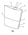
- eine schaubildliche Ansicht des twistierten Ruderblattes des Ruders,
- Fig. 3
- eine schaubildliche Skelettdarstellung des twistierten Ruderblattes mit entfernter Außenhaut und mit einer Anzahl von plattenförmigen Spanten in den beiden Ruderblattabschnitten,
- Fig. 4, 4A, 4B, 4C
- vier plattenförmige Spanten des oberen Ruderblattabschnittes des Ruderblattes gemäß
Fig. 3 , - Fig. 4D
- eine vergrößerte Darstellung eines plattenförmigen Spants des unteren Ruderblattabschnittes des Ruderblattes gemäß
Fig. 3 , - Fig. 4E
- einen plattenförmigen Spant des unteren Ruderblattabschnittes des Ruderblattes gemäß
Fig. 3 , - Fig.5
- eine vergrößerte Wiedergabe des plattenförmigen Spants gemäß
Fig. 4 , - Fig. 6
- eine vergrößerte Wiedergabe des plattenförmigen Spants gemäß
Fig. 4 mit Angaben zu den Abständen der Seitenkantenbereiche zur Längsmittellinie des Spants, - Fig. 7
- eine Skelettdarstellung einer weiteren Ausführungsform des twistierten Vollschweberuderblattes mit mehreren im oberen Ruderblattabschnitt und im unteren Ruderblattabschnitt angeordneten plattenförmigen Spanten,
- Fig. 8, 8A, 8B, 8C
- vergrößerte Ansichten von oben auf vier plattenförmige Spanten des oberen Ruderblattabschnittes des Ruderblattes gemäß
Fig. 7 mit Durchbrechungen für die Aufnahme des Kokerrohres für den Ruderschaft, - Fig. 8D, 8E, 8F
- vergrößerte Ansichten von oben auf drei plattenförmige Spanten des unteren Ruderblattabschnittes des Ruderblattes gemäß
Fig. 7 , - Fig. 9
- eine vergrößerte Ansicht von oben auf die Deckplatte des oberen Ruderblattabschnittes des Ruderblattes gemäß
Fig. 7 mit der Durchbrechung für die Aufnahme des Kokerrohres für den Ruderschaft, - Fig. 10
- eine vergrößerte Ansicht von unten auf das twistierte Ruderblatt des Ruders gemäß
Fig. 7 , - Fig. 11
- eine vergrößerte Ansicht von oben auf eine zwischen dem oberen Ruderblattabschnitt und dem unteren Ruderblattabschnitt des Ruders gemäß
Fig. 7 angeordnete Befestigungs- platte mit einem Profil und mit Abmessungen, die die Profile und Abmessungen der Bodenplatte des oberen Ruderblattabschnittes und der Deckplatte des unteren Ruderblattabschnittes mit einschließen, - Fig. 12
- eine Vorderansicht des twistierten Ruderblattes,
- Fig. 13
- eine Seitenansicht des Ruderblattes mit propellerseitig schräg verlaufenden Ruderblattkanten,
- Fig. 14
- eine Ansicht von oben auf das Querschnittsprofil eines Spants des oberen Ruderblattes einer weiteren Ausführungsform,
- Fig. 15
- einen senkrechten Schnitt der die Ruderschaftlagerung mit dem im oberen Ruderblattabschnitt angeordneten Kokerrohr für den Ruderschaft,
- Fig. 16
- eine schaubildliche Ansicht von unten auf das twistierte Ruderblatt mit strömungskörperartigen Leitblechen im Versetzungsbereich der beiden Ruderblattabschnitte des Ruders,
- Fig. 17
- eine Seitenansicht des Ruders gemäß
Fig. 16 , - Fig. 18
- eine Rückansicht des Ruders gemäß
Fig. 16 , - Fig. 19
- eine schaubildliche Vorderansicht des Ruders gemäß
Fig. 16 , - Fig. 20
- eine schaubildliche Seitenansicht des Ruders gemäß
Fig. 16 , - Fig. 21
- eine schaubildliche, vorderseitige Ansicht des Ruders gemäß
Fig. 16 , - Fig. 22
- eine Ansicht des Ruders gemäß
Fig. 16 von vorn auf die Nasenleisten des Ruderblattes mit s-förmig angeordneten Leitblechen, - Fig. 23
- eine Ansicht von unten auf das Ruder gemäß
Fig. 16 und - Fig. 24
- eine schaubildliche Ansicht von unten auf das twistierte Ruderblatt mit sich zu einem halbkugelförmigen Strömungskörper ergänzenden Leitblechen im Versetzungsbereich der beiden Ruderblattabschnitte des Ruders.
- Fig. 1
- a side view of the rudder with a twisted Vollschweberachsblatt with an upper and a lower rudder blade section and a rudder shaft mounted in the upper rudder blade section,
- Fig. 2
- a perspective view of the twisted rudder blade of the rudder,
- Fig. 3
- a diagrammatic skeleton representation of the twisted rudder blade with the outer skin removed and with a number of plate-shaped frames in the two rudder blade sections,
- Fig. 4, 4A, 4B, 4C
- four plate-shaped frames of the upper rudder blade portion of the rudder blade according to
Fig. 3 . - Fig. 4D
- an enlarged view of a plate-shaped frame of the lower rudder blade portion of the rudder blade according to
Fig. 3 . - Fig. 4E
- a plate-shaped bulkhead of the lower rudder blade portion of the rudder blade according to
Fig. 3 . - Figure 5
- an enlarged view of the plate-shaped frame according to
Fig. 4 . - Fig. 6
- an enlarged view of the plate-shaped frame according to
Fig. 4 with information on the distances of the side edge areas to the longitudinal center line of the frame, - Fig. 7
- a skeleton representation of another embodiment of the twisted Vollschweberachsblattes with a plurality of arranged in the upper rudder blade section and in the lower rudder blade section plate-shaped frames,
- Figs. 8, 8A, 8B, 8C
- enlarged views from above on four plate-shaped frames of the upper rudder blade portion of the rudder blade according to
Fig. 7 with openings for the reception of the coker tube for the rudder stock, - 8D, 8E, 8F
- enlarged views from above of three plate-shaped frames of the lower rudder blade portion of the rudder blade according to
Fig. 7 . - Fig. 9
- an enlarged view from above on the cover plate of the upper rudder blade portion of the rudder blade according to
Fig. 7 with the aperture for the reception of the coker tube for the rudder stock, - Fig. 10
- an enlarged view from below of the twisted rudder blade of the rudder according to
Fig. 7 . - Fig. 11
- an enlarged view from above on between the upper rudder blade portion and the lower rudder blade portion of the rudder according to
Fig. 7 arranged fastening plate having a profile and dimensions including the profiles and dimensions of the bottom plate of the upper rudder blade section and the cover plate of the lower rudder blade section, - Fig. 12
- a front view of the twisted rudder blade,
- Fig. 13
- a side view of the rudder blade with propeller-side inclined rudder blade edges,
- Fig. 14
- a top view of the cross-sectional profile of a rib of the upper rudder blade of another embodiment,
- Fig. 15
- a vertical section of the rudder stock with the arranged in the upper rudder blade section Kokerrohr for the rudder stock,
- Fig. 16
- a perspective view from below of the twisted rudder blade with Strömungskörperartigen baffles in the offset region of the two rudder blade sections of the rudder,
- Fig. 17
- a side view of the rudder according to
Fig. 16 . - Fig. 18
- a rear view of the rudder according to
Fig. 16 . - Fig. 19
- a diagrammatic front view of the rudder according to
Fig. 16 . - Fig. 20
- a perspective view of the rudder according to
Fig. 16 . - Fig. 21
- a perspective front view of the rudder according to
Fig. 16 . - Fig. 22
- a view of the rudder according to
Fig. 16 from the front on the nose strips of the rudder blade with s-shaped baffles, - Fig. 23
- a view from below of the rudder according to
Fig. 16 and - Fig. 24
- a perspective view from below of the twisted rudder blade with complementary to a hemispherical flow body baffles in the offset region of the two rudder blade sections of the rudder.
Das erfindungsgemäße Ruder 200 für Schiffe besteht aus zwei funktionell zusammenwirkenden Bauteilen, nämlich aus einem bevorzugterweise Vollschweberuder mit einem twistierten Ruderblatt 100 und einem in dessen oberen Bereich gelagerten Ruderschaft 140 (
Bei dem in
Das Ruderblatt 100 gemäß
Das Ruder 200 umfasst bevorzugterweise ein Vollschweberuder, wobei jedoch auch anders ausgebildete Ruder zum Einsatz kommen können, soweit diese für eine Ausstattung mit einem twistierten Ruderblatt geeignet sind und die Vorteile der erfindungsgemäßen Ruderblattausgestaltung erreicht werden. Die beiden übereinanderliegend angeordneten Ruderblattabschnitte 10, 20 weisen gleiche oder ungleiche Höhen auf. Bevorzugterweise weist der untere Ruderblattabschnitt 20 gegenüber der Höhe des oberen Ruderblattabschnittes eine geringe Höhe auf, wobei die Höhe des oberen Ruderblattabschnittes 10 mindestens dem 1 ½-Fachen der Höhe des unteren Ruderblattabschnittes 20 entspricht. Die Nasenleisten 11, 21 der beiden Ruderblattabschnitte 10, 20 sind halbkreisbogenförmig ausgebildet.The
Das Ruderblatt 100 weist konisch sich nach unten verjüngende bzw. verlaufende Nasenleisten 11, 21 auf, wohingegen die von den beiden Ruderblattabschnitten 10, 20 gebildete Endleiste 15 geradlinig und parallel zum Ruderschaft 140 verlaufend ist (
Wie
Die Längen L, L1 der Querschnittsflächenabschnitte 31, 32 der beiden Ruderblattabschnitte 10, 20 zu beiden Seiten der größten Profildicke PD sind unterschiedlich gestaltet. Die Querschnittsflächenabschnitte 31 des oberen Ruderblattabschnittes 20 und des unteren Ruderblattabschnittes 20 im Bereich zwischen der Endleiste 15 und der größten Profildicke PD des Ruderblattes 100 weisen gegenüber der Länge L1 der Querschnittsflächenabschnitte 32 des oberen Ruderblattabschnittes 10 und des unteren Ruderblattabschnittes 20 zwischen der größten Profildicke PD des Ruderblattes 100 und den Nasenleisten 11, 21 eine größere Länge L auf. Das Längenverhältnis beträgt dabei bevorzugterweise das 1 ½-Fache der Länge L gegenüber der Länge L1 (
Die Ausgestaltung des Ruderblattes ist derart, dass der oberen Ruderblattabschnitt 10 backbordseitig BB und der untere Ruderblattabschnitt 20 steuerbordseitig SB je einen flach bogenförmig verlaufenden und sich von den Nasenleisten 11, 21 in Richtung zu der Endleiste 15 erstreckenden Seitenwandabschnitte 18, 28 mit einer Länge L2 aufweisen, die der Länge L'2 des Seitenwandabschnittes 18 von den Nasenleisten 11, 21 bis zur größten Profildicke PD zuzüglich einer Länge L"2 entspricht, die mindestens der Länge L'2 entspricht, wobei sich an den flach bogenförmig verlaufenden Seitenwandabschnitt 28 der geradlinig verlaufende Seitenwandabschnitt 16 anschließt, der in die Endleiste 15 ausläuft (
Des Weiteren weisen der obere Ruderblattabschnitt 10 steuerbordseitig SB und der untere Ruderblattabschnitt 20 backbordseitig BB je einen stark gewölbt, bogenförmig verlaufenden und sich von den Nasenleisten 11, 21 in Richtung zu der Endleiste 15 erstreckende Seitenwandabschnitte 19, 29 mit einer Länge L3 auf, die der Länge L'3 des Seitenwandabschnittes 19 von den Nasenleisten 11, 21 bis zur größten Profildicke PD zuzüglich einer Länge L"3 entspricht, die mindestens der Länge L'3 entspricht. An den sich an den stark gewölbt verlaufenden bogenförmigen Seitenwandabschnitt 19, 29 schließt sich der geradlinig verlaufende Seitenwandabschnitt 17, 27 an, der in die Endleiste 15 ausläuft (
Aufgrund dieser Ausgestaltung der beiden Ruderblattabschnitte 10, 20 weisen die beidseitigen Seitenwandabschnitte von den Nasenleisten 11, 21 und von der Endleiste 15 in Richtung zur größten Profildicke PD ansteigende Verläufe auf.Due to this configuration of the two
Die Nasenleiste 11 des oberen Ruderblattabschnittes 10 und die Nasenleiste 21 des unteren Ruderblattabschnittes 20 nach Backbord BB und Steuerbord SB sind gegenüber der Längsmittellinie LML seitlich derart versetzt, dass die durch die seitlich versetzten Nasenleistenabschnitte gezogene Mittellinie M2 in einem Winkel α von mindestens 3° bis 10°, jedoch auch höher, bevorzugterweise 8°, zur Längsmittellinie LML der Querschnittsfläche eines Spants verlaufend ist.The
Das Ruder 200 umfasst ferner einen mit dem Ruderblatt 100 funktional zusammenwirkenden Ruderschaft 140, insbesondere aus Schmiedestahl oder einem anderen geeigneten Material, der in einem Kokerrohr 120, insbesondere aus Schmiedestahl oder einem anderen geeigneten Material vermittels mindestens einem Lager 150 gelagert ist. Der Ruderschaft 140 ist im Bereich der größten Profildicke PD des oberen Ruderblattabschnittes 10 und nur in diesem angeordnet (
Das tief in den oberen Ruderblattabschnitt 10 hineingezogene Kokerrohr 120 ist als Kragarm mit einer Innenbohrung 125 zur Aufnahme des Ruderschaftes 140 versehen (
Das Kokerrohr 120 ist als Kragträger mit einer mittigen Innenlängsbohrung 125 zur Aufnahme des Ruderschaftes 140 für das Ruderblatt 100 versehen. Außerdem ist das Kokerrohr 120 bis an das mit dem Ruderschaftende verbundene Ruderblatt 100 nur bis in den oberen Ruderblattabschnitt 10 hineinreichend ausgebildet. In seiner Innenbohrung 125 weist das Kokerrohr 120 das Lager 150 zur Lagerung des Ruderschaftes 140 auf, wobei bevorzugterweise dieses Lager 150 im unteren Endbereich 120b des Kokerrohres 120 angeordnet ist. Der Ruderschaft 140 ist mit seinem Ende 140b mit einem Abschnitt 145 aus dem Kokerrohr 120 herausgeführt. Das freie untere Ende dieses verlängerten Abschnittes 145 des Ruderschaftes 140 ist mit dem oberen Ruderblattabschnitt 10 bei 170 fest verbunden, wobei jedoch auch hier eine Verbindung vorgesehen ist, die ein Lösen des Ruderblattes 100 von dem Ruderschaft 140 ermöglicht, wenn z. B. die Propellerwelle ausgetauscht werden soll. Die Verbindung des Ruderschaftes 140 im Bereich 170 mit dem twistierten Ruderblatt 100 liegt dabei oberhalb der Propellerachse PA, so dass für den Ausbau der Propellerwelle lediglich das Ruderblatt 100 von dem Ruderschaft 140 abgenommen werden muss, so dass ein Herausziehen des Ruderschaftes 140 aus dem Kokerrohr 120 für einen Propellerachsenaustausch nicht erforderlich ist, da sowohl das freie untere Ende 120b des Kokerrohres als auch das freie untere Ende des Ruderschaftes 140 oberhalb der Propellerwellenmitte liegen. Bei der in
Zur Aufnahme des freien unteren Endes 120b des Kokerrohres 120 ist das Ruderblatt 100 mit einer bei 160 angedeuteten Einziehung bzw. Ausnehmung versehen.For receiving the free
Der Querschnitt des Kokerrohres 120 ist dünnwandig ausgeführt, das im Bereich seines freien Endes zur Lagerung des Ruderschaftes 140 innenwandseitig mindestens ein Halslager 130 aufweist. Auch an anderen Stellen des Kokerrohres 120 können zusätzliche Lager für den Ruderschaft vorgesehen sein. Der Ruderschaft 140 ist in seinem Endbereich 140b mit einem Abschnitt 140a aus dem Kokerrohr 120 herausgeführt und mit dem Ende dieses Abschnittes 140a mit dem oberen Ruderblattabschnitt 10 verbunden (
Nach
Wie die
Alle Spanten 50 des unteren Ruderblattabschnittes 20 weisen gleiche Formgebung, gleiche Seitenwandführung und übereinstimmende Nasenleisten 21 und Endleisten 15 auf, wobei die Länge der Spanten 50 von dem jeweils obersten Spant zum untersten Spant und somit auch die Größe der Querschnittsflächen der Spanten von oben nach unten abnimmt, so dass die Nasenleisten 11 zum Boden des unteren Ruderblattabschnittes 20 schräg verlaufend sind.All frames 50 of the lower
Aufgrund dieser Ausgestaltung verlaufen die Nasenleisten 11, 21 des oberen Ruderblattabschnittes 10 und des unteren Ruderblattabschnittes 20 schräg nach unten, wohingegen die Endleisten 15 geradlinig und parallel zur Längsachse des Ruderschaftes 140 verlaufen, wie in
Die beiden Ruderblattabschnitte 10, 20 können direkt miteinander verbunden sein. Bei den
Wie
Nach den
In
Der Durchmesser der Durchbrechung 105 bzw. Bohrung in dem oberen Ruderblattabschnitt 10 zur Aufnahme des Kokerrohres 120 für den Ruderschaft 140 ist etwas kleiner als die größte Profildicke PD des Ruderblattabschnittes 10. Aufgrund dieser Ausgestaltung wird ein sehr schlankes Ruderblattprofil geschaffen.The diameter of the
Die Ausgestaltung und das Querschnittsprofil des Ruderblattes 100 mit seinen beiden Ruderblattabschnitten 10, 20 sind derart, dass die flach gewölbten bogenförmigen Seitenwandabschnitte 18, 28 der oberen und unteren Ruderblattabschnitte 10, 20 eine kürze Länge L2, L'2 gegenüber der Länge L3 der stark gewölbten bogenförmigen Seitenwandabschnitte 19, 29 der oberen und unteren Ruderblattabschnitte 10, 20 aufweisen (![]()
![]()
![]()
![]()
![]()
![]()
Danach folgt die größte Profildicke PD. In Richtung zur Nasenleiste ergeben sich dann folgende Abstandsverhältnisse: ![]()
![]()
![]()
![]()
![]()
wobei das Verhältnis der Abstände α16 zu α17 etwa 2:1 ist. ![]()
![]()
![]()
![]()
![]()
wherein the ratio of the distances α16 to α17 is about 2: 1.
Die Bogenlänge BL1 der stark gewölbten bogenförmigen Seitenwandabschnitte 19, 29 des oberen und des unteren Ruderblattabschnittes 10, 20 ist nach einer weiteren Ausführungsform gemäß ![]()
![]()

(![]()
![]()
(
Die Schenkel der geradlinigen Seitenwandabschnitte 16, 17, 26, 27 des oberen Ruderblattabschnittes 10 und des unteren Ruderblattabschnittes 20, die zur Endleiste 15 zusammenlaufen, weisen bevorzugterweise gleiche Längen auf, jedoch auch eine ungleiche Längenausgestaltung ist möglich.The legs of the rectilinear
Die Erfindung umfasst auch Ruder, bei denen das twistierte Ruderblatt 100 mit einer sich über die beiden Ruderblattabschnitte 10, 20 erstreckenden Flosse versehen ist.The invention also includes rudders in which the
Wie die
Die beiden Leitbleche 200, 201 ergänzen sich zu einem Strömungskörper, der den Übergangsbereich zwischen den Versetzungsbereichen der beiden Ruderblattabschnitten 10, 20 abdeckt. Sowohl der obere Ruderblattabschnitt 10 als auch er untere Ruderblattabschnitt 20 weisen je ein streifenförmiges und leicht gewölbtes, der Außenwandform des Ruderblattes angepasstes Leitblech 200 bzw. 201 auf, wobei jedes der beiden Leitbleche mit einem den Nasenleisten 11, 21 bzw. dem Propeller 115 zugekehrten Abschnitt 200b bzw. 201 b im Bereich der Nasenleisten liegt und Bestandteil, d. h. integrierter Bestandteil der Nasenleiste ist. Des Weiteren ist jedes Leitblech 200 bzw. 201 mit einem rückwärtigen streifenförmigen Abschnitt 200c bzw. 201 c versehen, der an der Seitenwand des Ruders anliegt bzw. in diese integriert ist (
Die beiden kappenförmigen Abschnitte 200b, 201 b bilden zusammen zwei Kegelhälften 200'b, 201'b, die mit ihren Basisseiten aneinander stehen (
Die im Bereich der beiden Nasenleisten 11, 21 liegenden Abschnitte 200b, 201 b sind mit ihren einander zugekehrten Kanten 200d, 201 d miteinander und mit den Nasenleisten 11, 21 verschweißt (
Bei der Ausführungsform nach
Das erfindungsgemäße Ruder ist durch die in den Ansprüchen angegebenen Merkmale, durch die in der Beschreibung dargelegten Ausführungsformen und durch die in den Figuren der Zeichnungen dargestellten Ausführungsbeispiele gekennzeichnet. Die im Versetzungsbereich der beiden Ruderblattabschnitte 10, 20 angeordneten Leitbleche 200, 201 sowie 210 weisen die in der Beschreibung beschriebene und in den Figuren dargestellten Ausgestaltungen auf. und sind ebenfalls wie die Ruderblattausgestaltung Gegenstand der Erfindung.The rudder according to the invention is characterized by the features indicated in the claims, by the embodiments set forth in the description and by the embodiments illustrated in the figures of the drawings. The
Claims (11)
dadurch gekennzeichnet,
dass das Ruder (200)
characterized,
that the rudder (200)
dadurch gekennzeichnet,
dass der twistierte Bereich des Ruderblattes (100) geschlossene Übergänge aufweist.Rudder according to claim 1,
characterized,
twistierte that the area of the rudder blade (100) has closed transitions.
dadurch gekennzeichnet,
dass im Übergangsbereich der beiden seitlich versetzten Abschnitte der beiden übereinanderliegend angeordneten Ruderblattabschnitte (10, 20) dem bogenförmigen Verlauf der Nasenleisten (11, 21) entsprechend geformte Strömungskörper bildende, den Versatzbereich abdeckende Leitbleche (200, 201) mit einem strömungsgünstigen, gewölbten und der Außenwand des Ruderblattes angepassten, länglichen oder halbkugelförmigen Profil angeordnet, von denen sich ein Leitblech (200) von der Nasenleiste (11) des oberen Ruderblattabschnittes (10) bis in dessen Seitenwand und das andere Leitblech (201) von der Nasenleiste (21) des unteren Ruderblattabschnittes (20) bis in dessen Seitenwand erstreckt.Rudder according to one of claims 1 or 2,
characterized,
that in the transition region of the two laterally offset portions of the two superimposed rudder blade sections (10, 20) the arcuate course of the nose strips (11, 21) accordingly formed flow body forming, the offset region covering baffles (200, 201) arranged with a streamlined, curved and the outer wall of the rudder blade adapted, elongated or hemispherical profile, of which a guide plate (200) of the nose strip (11) of the upper rudder blade section (10 ) extends in the side wall and the other guide plate (201) of the nose strip (21) of the lower rudder blade portion (20) extends into the side wall thereof.
dadurch gekennzeichnet,
dass das Ruderblatt (100) funktional mit einem Ruderschaft (140) mit mindestens einem Lager zusammenwirkt,
characterized,
in that the rudder blade (100) cooperates functionally with a rudder stock (140) with at least one bearing,
dadurch gekennzeichnet,
dass zwischen dem oberen Ruderblattabschnitt (10) und dem unteren Ruderblattabschnitt (20) eine Befestigungsplatte (45) angeordnet und mit den Ruderblattabschnitten (10, 20) fest verbunden ist, wobei die Befestigungsplatte (45) symmetrische Querschnittsflächenabschnitte (46, 47) zu beiden Seiten der Längsmittellinie (LML) und ein Flächenprofil sowie Abmessungen aufweist, die die Bodenplatte (42) des oberen Ruderblattabschnittes (10) und die Deckplatte (41) des unteren Ruderblattabschnittes (20) mit ihren Profilen und Abmessungen mit einschließen.Rudder according to one of the preceding claims 1 to 4,
characterized,
that between the upper rudder blade section (10) and the lower rudder blade section (20) is arranged a mounting plate (45) and with the rudder blade sections (10, 20) is firmly connected, wherein the fastening plate (45) symmetrical cross-sectional surface sections (46, 47) on both sides the longitudinal center line (LML) and a surface profile and dimensions which include the bottom plate (42) of the upper rudder blade section (10) and the cover plate (41) of the lower rudder blade section (20) with their profiles and dimensions.
dadurch gekennzeichnet,
dass die Nasenleiste (11) des oberen Ruderblattabschnittes (10) und die Nasenleiste (21) des unteren Ruderblattabschnittes (20) nach Backbord (BB) und Steuerbord (SB) gegenüber der Längsmittellinie (LML) seitlich derart versetzt sind, dass die durch die seitlich versetzten Nasenleistenabschnitte gezogene Mittellinie (M2) in einem Winkel α von mindestens 3° bis 10°, jedoch auch höher, bevorzugterweise 8° zur Längsmittellinie (LML) der Querschnittsfläche eines Spants verlaufend ist.Rudder according to one of the preceding claims 1 to 5,
characterized,
in that the nose strip (11) of the upper rudder blade section (10) and the nose strip (21) of the lower rudder blade section (20) are laterally offset to port (BB) and starboard (SB) with respect to the longitudinal center line (LML) such that the laterally offset leading edge portions drawn center line (M2) at an angle α of at least 3 ° to 10 °, but also higher, preferably 8 ° to the longitudinal center line (LML) of the cross-sectional area of a rib running.
dadurch gekennzeichnet,
dass die backbordseitig (BB) und steuerbordseitig (SB) liegenden flach gewölbten bogenförmigen Seitenwandabschnitte (18, 28) der oberen und unteren Ruderblattabschnitte (10, 20) eine kürzere Länge (L4) gegenüber der Länge (L5) der steuerbordseitig (SB) und backbordseitig (BB) liegenden stark gewölbten bogenförmigen Seitenwandabschnitte (19, 29) der oberen und unteren Ruderblattabschnitte (10, 20) aufweisen.Rudder according to one of the preceding claims 1 to 6,
characterized,
that the port side (BB) and starboard side (SB) lying flat curved arcuate side wall portions (18, 28) of the upper and lower rudder blade sections (10, 20) have a shorter length (L4) than the length (L5) of the starboard side (SB) and port side (BB) strongly curved arcuate side wall sections (19, 29) of the upper and lower rudder blade sections (10, 20) ) respectively.
dadurch gekennzeichnet,
dass die Bogenlänge (BL1) der stark gewölbten bogenförmigen Seitenwandabschnitte (19, 29) des oberen und des unteren Ruderblattabschnittes (10, 20) größer ist als die Bogenlänge (BL) der flach gewölbten bogenförmigen Seitenwandabschnitte (18, 28) des oberen und des unteren Ruderblattabschnittes (10, 20), so dass die Übergangsbereiche (ÜB1) der stark gewölbten bogenförmigen Seitenwandabschnitte (19, 29) des oberen und des unteren Ruderblattabschnittes (10, 20) zu den geradlinig zu der Endleiste (15) verlaufenden Seitenwandabschnitten (17, 27) und die Übergangsbereiche (ÜB) der flach gewölbten bogenförmigen Seitenwandabschnitte (18, 28) des oberen und des unteren Ruderblattabschnittes (10, 20) zu den geradlinig zu der Endleiste (15) verlaufenden Seitenwandabschnitten (16, 26) in Richtung zur Endleiste versetzt sind.Rudder according to one of the preceding claims 1 to 7,
characterized,
in that the arc length (BL1) of the highly curved arcuate side wall portions (19, 29) of the upper and lower rudder blade portions (10, 20) is greater than the arc length (BL) of the arcuate arcuate side wall portions (18, 28) of the upper and lower ones Rudder blade section (10, 20), so that the transitional areas (ÜB1) of the strongly arched arcuate side wall sections (19, 29) of the upper and lower rudder blade sections (10, 20) extend to the side wall sections (17, 27) which are rectilinear to the end rail (15) ) and the transition areas (ÜB) of the arcuately curved arcuate side wall sections (18, 28) of the upper and lower rudder blade sections (10, 20) to the rectilinear to the end bar (15) extending side wall sections (16, 26) are offset towards the end bar ,
dadurch gekennzeichnet,
dass der Durchmesser der Durchbrechung (105) bzw. Bohrung in dem oberen Ruderblattabschnitt (10) zur Aufnahme des Kokerrohres (120) etwas kleiner gegenüber der größten Profildicke (PD) des Ruderblattabschnittes (10) ist.Rudder according to one of the preceding claims 1 to 8,
characterized,
that the diameter of the opening (105) or bore in the upper rudder blade section (10) for receiving the Kokerrohres (120) is slightly smaller than the largest profile thickness (PD) of the rudder blade section (10).
dadurch gekennzeichnet,
dass die dem Propeller (115) zugekehrte Kante bzw. Nasenleiste (11, 21) des Ruderblattes (100) zu der dem Propeller (115) abgekehrten Kante bzw. Endleiste (15) in einem Winkel β von mindestens 5°, bevorzugterweise 10°, schräg verlaufend ist.Oar according to one of the preceding claims 1 to 9,
characterized,
in that the edge or nose strip (11, 21) of the rudder blade (100) facing the propeller (115) faces the edge or end strip (15) facing away from the propeller (115) at an angle β of at least 5 °, preferably 10 °, is sloping.
dadurch gekennzeichnet,
dass die im Übergangsbereich der beiden seitlich versetzten Abschnitte (A1, A2) der beiden übereinanderliegend angeordneten Ruderblattabschnitte (10, 20) angeordneten dem bogenförmigen Verlauf der Nasenleisten (11, 21) entsprechend geformten Leitbleche (200, 201) ein gewölbtes, längliches Profil aufweisen, wobei jedes der beiden Leitbleche (200, 201) mit einem den Nasenleisten (11, 21) zugekehrten Abschnitt (200b, 201 b) im Bereich der Nasenleisten liegt und integrierter Bestandteil der Nasenleiste ist, und mit einem streifenförmigen Abschnitt (200c, 201c) versehen ist, der an der Seitenwand des Ruders anliegt oder in diese integriert ist, wobei die im Bereich der Nasenleisten (11, 21) liegenden Abschnitte (200b, 201 b) der beiden Leitbleche (200, 201) eine kappenförmige Ausgestaltung (200a, 201a) aufweisen, wobei die backbordseitige Seitenwand des oberen Ruderblattabschnittes (10) das Leitblech (200) und die steuerbordseitige liegende Seitenwand des unteren Ruderblattabschnittes (20) das Leitblech (201) aufweist, wobei die Leitbleche (200, 201) im Übergangsbereich des oberen Ruderblattabschnittes (10) und des unteren Ruderblattabschnittes (20) so angeordnet sind, dass die streifenförmigen Abschnitte (200c, 201c) in den Seitenwänden des Ruderblattes liegen und die Übergangsbereich abdecken, wobei die dem Propeller (115) zugekehrten Abschnitte (200b, 201 b) der Leitbleche (200, 201) im Bereich der Nasenleisten (11, 21) liegen.Rudder according to one of the preceding claims 1 to 10,
characterized,
that in the transition area of the two laterally displaced sections (A1, A2) of the two superimposed arranged rudder blade sections (10, 20) arranged in the arcuate profile of the leading edge (11, 21) correspondingly shaped guide plates (200, 201) having a curved, oblong profile, wherein each of the two baffles (200, 201) with a the nose strips (11, 21) facing portion (200b, 201 b) is in the region of the leading edge and is an integral part of the leading edge, and provided with a strip-shaped portion (200c, 201c) is, which rests on the side wall of the rudder or is integrated into it, wherein in the region of the nose strips (11, 21) lying portions (200b, 201 b) of the two guide plates (200, 201) has a cap-shaped configuration (200a, 201a) wherein the port side sidewall of the upper rudder blade section (10) includes the baffle (200) and the starboard side sidewall of the lower rudder blade sections s (20) has the baffle (201), wherein the baffles (200, 201) in the transition region of the upper rudder blade portion (10) and the lower rudder blade portion (20) are arranged so that the strip-shaped portions (200c, 201c) in the side walls lie the rudder blade and cover the transition region, wherein the propeller (115) facing portions (200b, 201 b) of the baffles (200, 201) in the region of the nose strips (11, 21) are located.
Priority Applications (1)
| Application Number | Priority Date | Filing Date | Title |
|---|---|---|---|
| EP08018925A EP2060486B1 (en) | 2007-11-13 | 2008-10-30 | Rudder for ships with high speeds with a cavitation reducing, twisted, in particular floating rudder |
Applications Claiming Priority (7)
| Application Number | Priority Date | Filing Date | Title |
|---|---|---|---|
| DE202007015941U DE202007015941U1 (en) | 2007-11-13 | 2007-11-13 | Oars for ships |
| EP07024061.9A EP2060484B2 (en) | 2007-11-13 | 2007-12-12 | Rudder for ships |
| DE202008010759 | 2008-08-13 | ||
| DE202008012125 | 2008-09-11 | ||
| DE202008013604 | 2008-10-14 | ||
| DE202008014375U DE202008014375U1 (en) | 2007-11-13 | 2008-10-29 | Rudder for ships at higher speeds with a cavitation-reducing, twisted, in particular Vollschweberuder |
| EP08018925A EP2060486B1 (en) | 2007-11-13 | 2008-10-30 | Rudder for ships with high speeds with a cavitation reducing, twisted, in particular floating rudder |
Publications (2)
| Publication Number | Publication Date |
|---|---|
| EP2060486A1 true EP2060486A1 (en) | 2009-05-20 |
| EP2060486B1 EP2060486B1 (en) | 2010-02-17 |
Family
ID=40547791
Family Applications (2)
| Application Number | Title | Priority Date | Filing Date |
|---|---|---|---|
| EP08018924A Active EP2060485B1 (en) | 2007-11-13 | 2008-10-30 | Rudder assembly for ships with high speeds with a cavitation reducing, twisted, in particular floating rudder |
| EP08018925A Active EP2060486B1 (en) | 2007-11-13 | 2008-10-30 | Rudder for ships with high speeds with a cavitation reducing, twisted, in particular floating rudder |
Family Applications Before (1)
| Application Number | Title | Priority Date | Filing Date |
|---|---|---|---|
| EP08018924A Active EP2060485B1 (en) | 2007-11-13 | 2008-10-30 | Rudder assembly for ships with high speeds with a cavitation reducing, twisted, in particular floating rudder |
Country Status (10)
| Country | Link |
|---|---|
| EP (2) | EP2060485B1 (en) |
| JP (2) | JP4901843B2 (en) |
| KR (3) | KR101466991B1 (en) |
| AT (2) | ATE458670T1 (en) |
| DE (2) | DE502008000377D1 (en) |
| ES (2) | ES2340741T3 (en) |
| HK (2) | HK1132718A1 (en) |
| HR (2) | HRP20100156T1 (en) |
| PT (2) | PT2060486E (en) |
| TW (2) | TWI363728B (en) |
Cited By (3)
| Publication number | Priority date | Publication date | Assignee | Title |
|---|---|---|---|---|
| CN107264763A (en) * | 2017-06-22 | 2017-10-20 | 中国人民解放军海军工程大学 | Anti-cavitation distorts rudder and its a kind of design method |
| EP3409575A1 (en) * | 2017-05-30 | 2018-12-05 | Becker Marine Systems GmbH | Rudder blade with a rudder blade hub and rudder blade hub for a rudder blade |
| CN108974312A (en) * | 2017-05-30 | 2018-12-11 | 贝克船舶系统有限公司 | Rudder blade with rudder blade wheel hub and the rudder blade wheel hub for rudder blade |
Families Citing this family (11)
| Publication number | Priority date | Publication date | Assignee | Title |
|---|---|---|---|---|
| KR101302733B1 (en) * | 2011-11-17 | 2013-09-03 | 현대중공업 주식회사 | Rudder of vessel and rudder part construction method of vessel |
| NO336848B1 (en) | 2013-03-08 | 2015-11-16 | Rolls Royce Marine As Rudders | rudder device |
| KR101942349B1 (en) | 2013-04-10 | 2019-01-25 | 현대중공업 주식회사 | Twist type rudder and vessel including the same |
| KR101939861B1 (en) * | 2014-05-26 | 2019-01-18 | 현대중공업 주식회사 | A rudder for ship |
| EP3489128A1 (en) * | 2017-11-28 | 2019-05-29 | Becker Marine Systems GmbH | Blade of an oar with modular structure, segment for a blade of an oar for a device for improving propulsion and method for producing a blade of an oar |
| KR102138459B1 (en) * | 2019-01-30 | 2020-07-27 | 한국조선해양 주식회사 | Steering apparatus and ship having the same |
| KR102024176B1 (en) * | 2019-06-11 | 2019-09-23 | 이상욱 | Manufacturing method of twisted type rudder |
| KR102305888B1 (en) * | 2020-01-30 | 2021-09-27 | 현대중공업 주식회사 | Steering apparatus and ship having the same |
| DE202020103872U1 (en) * | 2020-07-03 | 2020-08-13 | Becker Marine Systems Gmbh | Rowing trunk for a watercraft and watercraft with a rowing trunk |
| CN113371171B (en) * | 2021-06-18 | 2022-11-15 | 武汉理工大学 | Deformable rudder blade capable of adaptively deflecting front edge and deflection method |
| CN116788492B (en) * | 2023-08-22 | 2023-10-27 | 南通德玛瑞机械制造有限公司 | Rudder blade capable of being quickly assembled and disassembled and processing device thereof |
Citations (3)
| Publication number | Priority date | Publication date | Assignee | Title |
|---|---|---|---|---|
| GB332082A (en) | 1929-08-07 | 1930-07-17 | Amos Lowrey Ayre | Improvements in ships' rudders |
| JPS5830896A (en) | 1981-08-18 | 1983-02-23 | Ishikawajima Harima Heavy Ind Co Ltd | Reaction rudder without discontinuous part |
| DE202004006453U1 (en) * | 2004-04-23 | 2004-11-11 | Becker Marine Systems Gmbh & Co. Kg | Oars for ships |
Family Cites Families (13)
| Publication number | Priority date | Publication date | Assignee | Title |
|---|---|---|---|---|
| DE1140484B (en) * | 1958-04-30 | 1962-11-29 | Maierform Holding Sa | Ship rudder with staggered upper and lower rudder halves |
| FR1251898A (en) * | 1960-03-24 | 1961-01-20 | Eta Corp | Advanced rudder |
| JPS577798A (en) * | 1980-06-16 | 1982-01-14 | Mitsui Eng & Shipbuild Co Ltd | Reaction rudder |
| JPS6190700U (en) * | 1984-11-20 | 1986-06-12 | ||
| DE8708276U1 (en) * | 1987-06-12 | 1987-08-27 | Willi Becker Ingenieurbuero Gmbh, 2000 Hamburg, De | |
| JPH02144296A (en) * | 1988-11-25 | 1990-06-04 | Sumitomo Heavy Ind Ltd | Local flow generation preventing structure in discontinuous part of reaction rudder |
| JPH089359B2 (en) * | 1992-01-23 | 1996-01-31 | 川崎重工業株式会社 | Marine suspension rudder |
| JPH06305487A (en) * | 1993-04-21 | 1994-11-01 | Hitachi Zosen Corp | Rudder |
| JPH07237594A (en) * | 1994-02-28 | 1995-09-12 | Hitachi Zosen Corp | Rudder in ship |
| JPH0911990A (en) * | 1995-06-30 | 1997-01-14 | Hitachi Zosen Corp | Rudder |
| JPH11105794A (en) * | 1997-10-03 | 1999-04-20 | Sanoyasu Hishino Meisho:Kk | Deformation reaction rudder |
| KR100346512B1 (en) * | 1999-07-07 | 2002-08-01 | 삼성중공업 주식회사 | A rudder of ship |
| DE202005013583U1 (en) * | 2005-06-30 | 2005-11-03 | Becker Marine Systems Gmbh & Co. Kg | Rudder stock for water craft, has end sections made of wrought iron, and middle stock section connected with end sections and made of carbon fibrous composite or graphite fibers, which form middle stock section in the form of windings |
-
2008
- 2008-10-30 PT PT08018925T patent/PT2060486E/en unknown
- 2008-10-30 PT PT08018924T patent/PT2060485E/en unknown
- 2008-10-30 AT AT08018924T patent/ATE458670T1/en active
- 2008-10-30 ES ES08018925T patent/ES2340741T3/en active Active
- 2008-10-30 ES ES08018924T patent/ES2341393T3/en active Active
- 2008-10-30 DE DE502008000377T patent/DE502008000377D1/en active Active
- 2008-10-30 EP EP08018924A patent/EP2060485B1/en active Active
- 2008-10-30 AT AT08018925T patent/ATE457925T1/en active
- 2008-10-30 EP EP08018925A patent/EP2060486B1/en active Active
- 2008-10-30 DE DE502008000400T patent/DE502008000400D1/en active Active
- 2008-11-10 TW TW097143320A patent/TWI363728B/en active
- 2008-11-10 TW TW097143317A patent/TWI370084B/en active
- 2008-11-11 KR KR1020080111796A patent/KR101466991B1/en active IP Right Grant
- 2008-11-12 JP JP2008289823A patent/JP4901843B2/en active Active
- 2008-11-12 JP JP2008289824A patent/JP5175690B2/en active Active
- 2008-11-12 KR KR1020080112137A patent/KR20090049551A/en active Search and Examination
-
2009
- 2009-11-13 HK HK09110620.8A patent/HK1132718A1/en unknown
- 2009-11-13 HK HK09110623.5A patent/HK1132719A1/en unknown
-
2010
- 2010-03-18 HR HR20100156T patent/HRP20100156T1/en unknown
- 2010-05-24 HR HR20100291T patent/HRP20100291T1/en unknown
-
2013
- 2013-03-29 KR KR1020130034026A patent/KR101421375B1/en active IP Right Grant
Patent Citations (3)
| Publication number | Priority date | Publication date | Assignee | Title |
|---|---|---|---|---|
| GB332082A (en) | 1929-08-07 | 1930-07-17 | Amos Lowrey Ayre | Improvements in ships' rudders |
| JPS5830896A (en) | 1981-08-18 | 1983-02-23 | Ishikawajima Harima Heavy Ind Co Ltd | Reaction rudder without discontinuous part |
| DE202004006453U1 (en) * | 2004-04-23 | 2004-11-11 | Becker Marine Systems Gmbh & Co. Kg | Oars for ships |
Cited By (5)
| Publication number | Priority date | Publication date | Assignee | Title |
|---|---|---|---|---|
| EP3409575A1 (en) * | 2017-05-30 | 2018-12-05 | Becker Marine Systems GmbH | Rudder blade with a rudder blade hub and rudder blade hub for a rudder blade |
| CN108974312A (en) * | 2017-05-30 | 2018-12-11 | 贝克船舶系统有限公司 | Rudder blade with rudder blade wheel hub and the rudder blade wheel hub for rudder blade |
| CN108974312B (en) * | 2017-05-30 | 2022-08-30 | 贝克船舶系统有限公司 | Rudder blade with a rudder blade hub and rudder blade hub for a rudder blade |
| CN107264763A (en) * | 2017-06-22 | 2017-10-20 | 中国人民解放军海军工程大学 | Anti-cavitation distorts rudder and its a kind of design method |
| CN107264763B (en) * | 2017-06-22 | 2019-08-02 | 中国人民解放军海军工程大学 | A kind of design method of anti-cavitation distortion rudder |
Also Published As
| Publication number | Publication date |
|---|---|
| HK1132719A1 (en) | 2010-03-05 |
| EP2060486B1 (en) | 2010-02-17 |
| EP2060485A1 (en) | 2009-05-20 |
| HK1132718A1 (en) | 2010-03-05 |
| KR20090049551A (en) | 2009-05-18 |
| JP4901843B2 (en) | 2012-03-21 |
| PT2060486E (en) | 2010-03-12 |
| TW200932628A (en) | 2009-08-01 |
| TW200930617A (en) | 2009-07-16 |
| DE502008000377D1 (en) | 2010-04-01 |
| KR101466991B1 (en) | 2014-12-01 |
| ES2340741T3 (en) | 2010-06-08 |
| JP2009120190A (en) | 2009-06-04 |
| HRP20100291T1 (en) | 2010-06-30 |
| ATE458670T1 (en) | 2010-03-15 |
| TWI363728B (en) | 2012-05-11 |
| PT2060485E (en) | 2010-06-08 |
| ES2341393T3 (en) | 2010-06-18 |
| JP5175690B2 (en) | 2013-04-03 |
| KR20130039747A (en) | 2013-04-22 |
| TWI370084B (en) | 2012-08-11 |
| JP2009120191A (en) | 2009-06-04 |
| KR101421375B1 (en) | 2014-08-13 |
| EP2060485B1 (en) | 2010-02-24 |
| HRP20100156T1 (en) | 2010-04-30 |
| ATE457925T1 (en) | 2010-03-15 |
| KR20090049545A (en) | 2009-05-18 |
| DE502008000400D1 (en) | 2010-04-08 |
Similar Documents
| Publication | Publication Date | Title |
|---|---|---|
| EP2060486B1 (en) | Rudder for ships with high speeds with a cavitation reducing, twisted, in particular floating rudder | |
| EP2154064B1 (en) | Rudder assembly for ships with high speeds with a cavitation reducing, twisted, in particular floating rudder | |
| EP2060484B2 (en) | Rudder for ships | |
| EP1921005B1 (en) | Rudder for ships | |
| EP2060483A1 (en) | High-performance rudder for ships | |
| EP1857358B1 (en) | Rudder for ships | |
| DE202013101943U1 (en) | Device for reducing the power requirement of a watercraft | |
| DE3814943A1 (en) | Rudder, in particular balance profile rudder for watercraft | |
| WO2003070567A1 (en) | Line design and propulsion system for a directionally stable, seagoing boat with rudder propeller drive system | |
| EP1818543B1 (en) | Blade for impeller | |
| EP2281743A1 (en) | Propeller engine pod | |
| DE102017101680A1 (en) | Hydrofoil for a watercraft | |
| EP3409575B1 (en) | Rudder blade with a rudder blade hub and rudder blade hub for a rudder blade | |
| EP3544887B1 (en) | Nozzle of a ship propeller | |
| DE202017103233U1 (en) | Rudder blade with a rudder blade hub and rudder blade hub for a rudder blade | |
| DE202007017450U1 (en) | High efficiency rudder for ships | |
| EP1787904B1 (en) | High-load suspended rudder | |
| DE202008014375U1 (en) | Rudder for ships at higher speeds with a cavitation-reducing, twisted, in particular Vollschweberuder | |
| DE3408532A1 (en) | Arrangement for reducing the hydrodynamic resistance of hulls | |
| EP3464045B1 (en) | Water vehicle, in particular tugboat | |
| EP1306301B1 (en) | Device for counteracting hub vortex cavitation of propellers and/or marine propulsion units | |
| EP1203715A2 (en) | Ship, especially fast ship with PoD propulsion | |
| DE10240534B4 (en) | ship | |
| DE3302180A1 (en) | Braking and auxiliary control device for ships | |
| DE3011653A1 (en) | METHOD FOR PRODUCING A RUDDER WITH CROSS-FEDERED RUDDER-PROPERTIES FROM A NORMAL PROFILE RUDDER, AND A subsequently-made RUDDER FOR WATER VEHICLES AND FLOATING DEVICE |
Legal Events
| Date | Code | Title | Description |
|---|---|---|---|
| PUAI | Public reference made under article 153(3) epc to a published international application that has entered the european phase |
Free format text: ORIGINAL CODE: 0009012 |
|
| 17P | Request for examination filed |
Effective date: 20090328 |
|
| AK | Designated contracting states |
Kind code of ref document: A1 Designated state(s): AT BE BG CH CY CZ DE DK EE ES FI FR GB GR HR HU IE IS IT LI LT LU LV MC MT NL NO PL PT RO SE SI SK TR |
|
| AX | Request for extension of the european patent |
Extension state: AL BA MK RS |
|
| GRAP | Despatch of communication of intention to grant a patent |
Free format text: ORIGINAL CODE: EPIDOSNIGR1 |
|
| GRAS | Grant fee paid |
Free format text: ORIGINAL CODE: EPIDOSNIGR3 |
|
| GRAA | (expected) grant |
Free format text: ORIGINAL CODE: 0009210 |
|
| AKX | Designation fees paid |
Designated state(s): AT BE BG CH CY CZ DE DK EE ES FI FR GB GR HR HU IE IS IT LI LT LU LV MC MT NL NO PL PT RO SE SI SK TR |
|
| AK | Designated contracting states |
Kind code of ref document: B1 Designated state(s): AT BE BG CH CY CZ DE DK EE ES FI FR GB GR HR HU IE IS IT LI LT LU LV MC MT NL NO PL PT RO SE SI SK TR |
|
| REG | Reference to a national code |
Ref country code: GB Ref legal event code: FG4D Free format text: NOT ENGLISH |
|
| REG | Reference to a national code |
Ref country code: CH Ref legal event code: EP |
|
| REG | Reference to a national code |
Ref country code: PT Ref legal event code: SC4A Free format text: AVAILABILITY OF NATIONAL TRANSLATION Effective date: 20100302 |
|
| REG | Reference to a national code |
Ref country code: IE Ref legal event code: FG4D Free format text: LANGUAGE OF EP DOCUMENT: GERMAN |
|
| REG | Reference to a national code |
Ref country code: HR Ref legal event code: TUEP Ref document number: P20100156 Country of ref document: HR |
|
| REF | Corresponds to: |
Ref document number: 502008000377 Country of ref document: DE Date of ref document: 20100401 Kind code of ref document: P |
|
| REG | Reference to a national code |
Ref country code: RO Ref legal event code: EPE |
|
| REG | Reference to a national code |
Ref country code: NL Ref legal event code: T3 |
|
| REG | Reference to a national code |
Ref country code: HR Ref legal event code: T1PR Ref document number: P20100156 Country of ref document: HR |
|
| REG | Reference to a national code |
Ref country code: ES Ref legal event code: FG2A Ref document number: 2340741 Country of ref document: ES Kind code of ref document: T3 |
|
| LTIE | Lt: invalidation of european patent or patent extension |
Effective date: 20100217 |
|
| PG25 | Lapsed in a contracting state [announced via postgrant information from national office to epo] |
Ref country code: LT Free format text: LAPSE BECAUSE OF FAILURE TO SUBMIT A TRANSLATION OF THE DESCRIPTION OR TO PAY THE FEE WITHIN THE PRESCRIBED TIME-LIMIT Effective date: 20100217 Ref country code: IS Free format text: LAPSE BECAUSE OF FAILURE TO SUBMIT A TRANSLATION OF THE DESCRIPTION OR TO PAY THE FEE WITHIN THE PRESCRIBED TIME-LIMIT Effective date: 20100617 |
|
| PG25 | Lapsed in a contracting state [announced via postgrant information from national office to epo] |
Ref country code: SI Free format text: LAPSE BECAUSE OF FAILURE TO SUBMIT A TRANSLATION OF THE DESCRIPTION OR TO PAY THE FEE WITHIN THE PRESCRIBED TIME-LIMIT Effective date: 20100217 Ref country code: PL Free format text: LAPSE BECAUSE OF FAILURE TO SUBMIT A TRANSLATION OF THE DESCRIPTION OR TO PAY THE FEE WITHIN THE PRESCRIBED TIME-LIMIT Effective date: 20100217 Ref country code: LV Free format text: LAPSE BECAUSE OF FAILURE TO SUBMIT A TRANSLATION OF THE DESCRIPTION OR TO PAY THE FEE WITHIN THE PRESCRIBED TIME-LIMIT Effective date: 20100217 |
|
| REG | Reference to a national code |
Ref country code: IE Ref legal event code: FD4D |
|
| PG25 | Lapsed in a contracting state [announced via postgrant information from national office to epo] |
Ref country code: SE Free format text: LAPSE BECAUSE OF FAILURE TO SUBMIT A TRANSLATION OF THE DESCRIPTION OR TO PAY THE FEE WITHIN THE PRESCRIBED TIME-LIMIT Effective date: 20100217 Ref country code: IE Free format text: LAPSE BECAUSE OF FAILURE TO SUBMIT A TRANSLATION OF THE DESCRIPTION OR TO PAY THE FEE WITHIN THE PRESCRIBED TIME-LIMIT Effective date: 20100217 Ref country code: GR Free format text: LAPSE BECAUSE OF FAILURE TO SUBMIT A TRANSLATION OF THE DESCRIPTION OR TO PAY THE FEE WITHIN THE PRESCRIBED TIME-LIMIT Effective date: 20100518 Ref country code: CY Free format text: LAPSE BECAUSE OF FAILURE TO SUBMIT A TRANSLATION OF THE DESCRIPTION OR TO PAY THE FEE WITHIN THE PRESCRIBED TIME-LIMIT Effective date: 20100217 Ref country code: EE Free format text: LAPSE BECAUSE OF FAILURE TO SUBMIT A TRANSLATION OF THE DESCRIPTION OR TO PAY THE FEE WITHIN THE PRESCRIBED TIME-LIMIT Effective date: 20100217 |
|
| PG25 | Lapsed in a contracting state [announced via postgrant information from national office to epo] |
Ref country code: BG Free format text: LAPSE BECAUSE OF FAILURE TO SUBMIT A TRANSLATION OF THE DESCRIPTION OR TO PAY THE FEE WITHIN THE PRESCRIBED TIME-LIMIT Effective date: 20100517 Ref country code: SK Free format text: LAPSE BECAUSE OF FAILURE TO SUBMIT A TRANSLATION OF THE DESCRIPTION OR TO PAY THE FEE WITHIN THE PRESCRIBED TIME-LIMIT Effective date: 20100217 Ref country code: CZ Free format text: LAPSE BECAUSE OF FAILURE TO SUBMIT A TRANSLATION OF THE DESCRIPTION OR TO PAY THE FEE WITHIN THE PRESCRIBED TIME-LIMIT Effective date: 20100217 |
|
| PLBE | No opposition filed within time limit |
Free format text: ORIGINAL CODE: 0009261 |
|
| STAA | Information on the status of an ep patent application or granted ep patent |
Free format text: STATUS: NO OPPOSITION FILED WITHIN TIME LIMIT |
|
| REG | Reference to a national code |
Ref country code: NO Ref legal event code: T2 Effective date: 20100217 |
|
| 26N | No opposition filed |
Effective date: 20101118 |
|
| PG25 | Lapsed in a contracting state [announced via postgrant information from national office to epo] |
Ref country code: DK Free format text: LAPSE BECAUSE OF FAILURE TO SUBMIT A TRANSLATION OF THE DESCRIPTION OR TO PAY THE FEE WITHIN THE PRESCRIBED TIME-LIMIT Effective date: 20100217 |
|
| BERE | Be: lapsed |
Owner name: BECKER MARINE SYSTEMS G.M.B.H. & CO. KG Effective date: 20101031 |
|
| PG25 | Lapsed in a contracting state [announced via postgrant information from national office to epo] |
Ref country code: MC Free format text: LAPSE BECAUSE OF NON-PAYMENT OF DUE FEES Effective date: 20101031 |
|
| PG25 | Lapsed in a contracting state [announced via postgrant information from national office to epo] |
Ref country code: BE Free format text: LAPSE BECAUSE OF NON-PAYMENT OF DUE FEES Effective date: 20101031 |
|
| PG25 | Lapsed in a contracting state [announced via postgrant information from national office to epo] |
Ref country code: MT Free format text: LAPSE BECAUSE OF FAILURE TO SUBMIT A TRANSLATION OF THE DESCRIPTION OR TO PAY THE FEE WITHIN THE PRESCRIBED TIME-LIMIT Effective date: 20100217 |
|
| PG25 | Lapsed in a contracting state [announced via postgrant information from national office to epo] |
Ref country code: LU Free format text: LAPSE BECAUSE OF NON-PAYMENT OF DUE FEES Effective date: 20101030 Ref country code: HU Free format text: LAPSE BECAUSE OF FAILURE TO SUBMIT A TRANSLATION OF THE DESCRIPTION OR TO PAY THE FEE WITHIN THE PRESCRIBED TIME-LIMIT Effective date: 20100818 |
|
| REG | Reference to a national code |
Ref country code: CH Ref legal event code: PL |
|
| GBPC | Gb: european patent ceased through non-payment of renewal fee |
Effective date: 20121030 |
|
| PG25 | Lapsed in a contracting state [announced via postgrant information from national office to epo] |
Ref country code: CH Free format text: LAPSE BECAUSE OF NON-PAYMENT OF DUE FEES Effective date: 20121031 Ref country code: LI Free format text: LAPSE BECAUSE OF NON-PAYMENT OF DUE FEES Effective date: 20121031 Ref country code: GB Free format text: LAPSE BECAUSE OF NON-PAYMENT OF DUE FEES Effective date: 20121030 |
|
| REG | Reference to a national code |
Ref country code: AT Ref legal event code: MM01 Ref document number: 457925 Country of ref document: AT Kind code of ref document: T Effective date: 20131030 |
|
| PG25 | Lapsed in a contracting state [announced via postgrant information from national office to epo] |
Ref country code: AT Free format text: LAPSE BECAUSE OF NON-PAYMENT OF DUE FEES Effective date: 20131030 |
|
| REG | Reference to a national code |
Ref country code: FR Ref legal event code: PLFP Year of fee payment: 8 |
|
| PGFP | Annual fee paid to national office [announced via postgrant information from national office to epo] |
Ref country code: PT Payment date: 20151022 Year of fee payment: 8 |
|
| REG | Reference to a national code |
Ref country code: FR Ref legal event code: PLFP Year of fee payment: 9 |
|
| PG25 | Lapsed in a contracting state [announced via postgrant information from national office to epo] |
Ref country code: PT Free format text: LAPSE BECAUSE OF NON-PAYMENT OF DUE FEES Effective date: 20170502 |
|
| REG | Reference to a national code |
Ref country code: FR Ref legal event code: PLFP Year of fee payment: 10 |
|
| PGFP | Annual fee paid to national office [announced via postgrant information from national office to epo] |
Ref country code: RO Payment date: 20171024 Year of fee payment: 10 |
|
| REG | Reference to a national code |
Ref country code: DE Ref legal event code: R082 Ref document number: 502008000377 Country of ref document: DE Representative=s name: RGTH RICHTER GERBAULET THIELEMANN HOFMANN PATE, DE Ref country code: DE Ref legal event code: R081 Ref document number: 502008000377 Country of ref document: DE Owner name: BECKER MARINE SYSTEMS GMBH, DE Free format text: FORMER OWNER: BECKER MARINE SYSTEMS GMBH & CO. KG, 21079 HAMBURG, DE |
|
| REG | Reference to a national code |
Ref country code: FR Ref legal event code: PLFP Year of fee payment: 11 |
|
| REG | Reference to a national code |
Ref country code: HR Ref legal event code: ODRP Ref document number: P20100156 Country of ref document: HR Payment date: 20181025 Year of fee payment: 11 |
|
| PG25 | Lapsed in a contracting state [announced via postgrant information from national office to epo] |
Ref country code: RO Free format text: LAPSE BECAUSE OF NON-PAYMENT OF DUE FEES Effective date: 20181030 |
|
| REG | Reference to a national code |
Ref country code: HR Ref legal event code: ODRP Ref document number: P20100156 Country of ref document: HR Payment date: 20191024 Year of fee payment: 12 |
|
| REG | Reference to a national code |
Ref country code: HR Ref legal event code: ODRP Ref document number: P20100156 Country of ref document: HR Payment date: 20201022 Year of fee payment: 13 |
|
| REG | Reference to a national code |
Ref country code: HR Ref legal event code: ODRP Ref document number: P20100156 Country of ref document: HR Payment date: 20211021 Year of fee payment: 14 |
|
| REG | Reference to a national code |
Ref country code: HR Ref legal event code: ODRP Ref document number: P20100156 Country of ref document: HR Payment date: 20221018 Year of fee payment: 15 |
|
| P01 | Opt-out of the competence of the unified patent court (upc) registered |
Effective date: 20230529 |
|
| REG | Reference to a national code |
Ref country code: HR Ref legal event code: ODRP Ref document number: P20100156 Country of ref document: HR Payment date: 20231019 Year of fee payment: 16 |
|
| PGFP | Annual fee paid to national office [announced via postgrant information from national office to epo] |
Ref country code: NL Payment date: 20231023 Year of fee payment: 16 |
|
| PGFP | Annual fee paid to national office [announced via postgrant information from national office to epo] |
Ref country code: ES Payment date: 20231117 Year of fee payment: 16 |
|
| PGFP | Annual fee paid to national office [announced via postgrant information from national office to epo] |
Ref country code: TR Payment date: 20231019 Year of fee payment: 16 Ref country code: NO Payment date: 20231023 Year of fee payment: 16 Ref country code: IT Payment date: 20231031 Year of fee payment: 16 Ref country code: HR Payment date: 20231019 Year of fee payment: 16 Ref country code: FR Payment date: 20231023 Year of fee payment: 16 Ref country code: FI Payment date: 20231023 Year of fee payment: 16 Ref country code: DE Payment date: 20231101 Year of fee payment: 16 |