DE202013101943U1 - Device for reducing the power requirement of a watercraft - Google Patents
Device for reducing the power requirement of a watercraft Download PDFInfo
- Publication number
- DE202013101943U1 DE202013101943U1 DE202013101943U DE202013101943U DE202013101943U1 DE 202013101943 U1 DE202013101943 U1 DE 202013101943U1 DE 202013101943 U DE202013101943 U DE 202013101943U DE 202013101943 U DE202013101943 U DE 202013101943U DE 202013101943 U1 DE202013101943 U1 DE 202013101943U1
- Authority
- DE
- Germany
- Prior art keywords
- fin
- propeller
- flow guide
- nozzle
- fins
- Prior art date
- Legal status (The legal status is an assumption and is not a legal conclusion. Google has not performed a legal analysis and makes no representation as to the accuracy of the status listed.)
- Expired - Lifetime
Links
Images


Classifications
-
- B—PERFORMING OPERATIONS; TRANSPORTING
- B63—SHIPS OR OTHER WATERBORNE VESSELS; RELATED EQUIPMENT
- B63H—MARINE PROPULSION OR STEERING
- B63H1/00—Propulsive elements directly acting on water
- B63H1/02—Propulsive elements directly acting on water of rotary type
- B63H1/12—Propulsive elements directly acting on water of rotary type with rotation axis substantially in propulsive direction
- B63H1/14—Propellers
- B63H1/28—Other means for improving propeller efficiency
-
- B—PERFORMING OPERATIONS; TRANSPORTING
- B63—SHIPS OR OTHER WATERBORNE VESSELS; RELATED EQUIPMENT
- B63H—MARINE PROPULSION OR STEERING
- B63H5/00—Arrangements on vessels of propulsion elements directly acting on water
- B63H5/07—Arrangements on vessels of propulsion elements directly acting on water of propellers
- B63H5/16—Arrangements on vessels of propulsion elements directly acting on water of propellers characterised by being mounted in recesses; with stationary water-guiding elements; Means to prevent fouling of the propeller, e.g. guards, cages or screens
-
- F—MECHANICAL ENGINEERING; LIGHTING; HEATING; WEAPONS; BLASTING
- F04—POSITIVE - DISPLACEMENT MACHINES FOR LIQUIDS; PUMPS FOR LIQUIDS OR ELASTIC FLUIDS
- F04D—NON-POSITIVE-DISPLACEMENT PUMPS
- F04D29/00—Details, component parts, or accessories
- F04D29/40—Casings; Connections of working fluid
-
- Y—GENERAL TAGGING OF NEW TECHNOLOGICAL DEVELOPMENTS; GENERAL TAGGING OF CROSS-SECTIONAL TECHNOLOGIES SPANNING OVER SEVERAL SECTIONS OF THE IPC; TECHNICAL SUBJECTS COVERED BY FORMER USPC CROSS-REFERENCE ART COLLECTIONS [XRACs] AND DIGESTS
- Y02—TECHNOLOGIES OR APPLICATIONS FOR MITIGATION OR ADAPTATION AGAINST CLIMATE CHANGE
- Y02T—CLIMATE CHANGE MITIGATION TECHNOLOGIES RELATED TO TRANSPORTATION
- Y02T70/00—Maritime or waterways transport
- Y02T70/50—Measures to reduce greenhouse gas emissions related to the propulsion system
Abstract
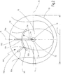
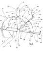
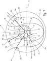
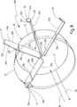
Vorrichtung (100) zur Verringerung des Antriebsleistungsbedarfs eines Wasserfahrzeugs, insbesondere eines Schiffes, umfassend eine Strömungsleitfläche (50), wobei von der Strömungsleitfläche (50) mindestens ein erster Fin (50a) vorsteht, dadurch gekennzeichnet, dass ein erstes Ende (201, 501) des ersten Fins (50a) an der Strömungsleitfläche (50) befestigt ist, und ein zweites Ende (502) des ersten Fins (50a) als freies Ende ausgebildet ist.Device (100) for reducing the power requirement of a watercraft, in particular a ship, comprising a flow guide surface (50), wherein at least one first fin (50a) projects from the flow guide surface (50), characterized in that a first end (201, 501) of the first fin (50a) is attached to the flow guide surface (50), and a second end (502) of the first fin (50a) is formed as a free end.
Description
Die Erfindung betrifft eine Vorrichtung zur Verringerung des Antriebsleistungsbedarfs eines Wasserfahrzeuges, insbesondere eines Schiffes. Die Vorrichtung gemäß der Erfindung ist insbesondere geeignet für ein Antriebssystem eines Wasserfahrzeuges zur Verbesserung der Energieeffizienz.The invention relates to a device for reducing the power requirement of a watercraft, in particular a ship. The device according to the invention is particularly suitable for a propulsion system of a watercraft for improving the energy efficiency.
Aus dem Stand der Technik sind Vorrichtungen zur Verringerung des Antriebsleistungsbedarfs eines Wasserfahrzeuges bekannt. Bei der
Die vorbekannte, oben beschriebene Vorrichtung weist jedoch einen relativ großen Widerstand für die Propellerzuströmung auf, so dass sich die Verringerung des Antriebsleistungsbedarfs in relevantem Ausmaße vorwiegend nur bei langsameren bzw. völligeren Schiffen einstellt, so dass die bekannte Vorrichtung auch in der Regel nur bei derartigen Schiffen eingesetzt wird.However, the prior art device described above has a relatively large resistance to the propeller inflow, so that the reduction of the power requirement in relevant proportions predominantly occurs only in slower or more complete ships, so that the known device also usually only in such ships is used.
Daher ist es Aufgabe der vorliegenden Erfindung, eine Vorrichtung zur Verringerung des Antriebsleistungsbedarfs eines Wasserfahrzeuges anzugeben, die insbesondere auch wirkungsvoll bei schnellen und sehr schnellen Wasserfahrzeugen, beispielsweise Schiffen mit einer Geschwindigkeit von 20 Knoten oder mehr bzw. 25 Knoten und mehr, einsetzbar ist.It is therefore an object of the present invention to provide a device for reducing the power requirement of a watercraft, which is particularly effective in fast and very fast watercraft, such as ships at a speed of 20 knots or more or 25 knots and more, can be used.
Diese Aufgabe wird dadurch gelöst, dass bei einer Vorrichtung zur Verringerung des Antriebsleistungsbedarfs eines Wasserfahrzeugs, die eine Strömungsleitfläche umfasst, mindestens ein erster Fin von der Strömungsleitfläche derart vorsteht, das ein erstes Ende des ersten Fins an der Strömungsleitfläche befestigt ist und ein zweites Ende des ersten Fins als freies Ende ausgebildet ist.This object is achieved in that in a device for reducing the power requirement of a vessel comprising a Strömungsleitfläche, at least a first fin of the Strömungsleitfläche projects such that a first end of the first fin is attached to the flow guide and a second end of the first Fins is designed as a free end.
Die Strömungsleitfläche kann einteilig beziehungsweise einstückig ausgebildet sein, oder aus mehreren Einzelteilen zu einer Strömungsleitfläche zusammengesetzt sein, wobei die Einzelteile bevorzugt miteinander beziehungsweise mit der Schiffshülle verschweißt sind.The flow guide can be formed in one piece or in one piece, or be composed of several items to a flow guide, the items are preferably welded together or with the hull.
Die Strömungsleitfläche kann grundsätzlich alle möglichen Formen aufweisen. Dabei ist die Strömungsleitfläche derart angeordnet und ausgebildet, dass durch sie die Wasserströmung zumindest teilweise auf einen Propeller geleitet wird. Beispielsweise kann die Strömungsleitfläche die Form einer quadratischen oder rechteckigen Platte aufweisen. Ferner sind bogenförmige oder gewölbte Ausbildungen denkbar. Im Querschnitt kann eine bogenförmig ausgebildete Strömungsleitfläche einen Kreisausschnitt, einen Ellipsenausschnitt oder auch eine anderweitig gebogene Form aufweisen. Die Strömungsleitfläche weist in Strömungsrichtung, beziehungsweise in Fahrtrichtung des Wasserfahrzeugs, eine Länge auf. Ferner weist die Strömungsleitfläche bei einer plattenförmigen Ausgestaltung eine Breite, beziehungsweise bei einer bogenförmigen Ausgestaltung eine Bogenlänge auf. Die Dicke der Strömungsleitfläche wird im Folgenden als Profildicke bezeichnet. Sowohl die Länge, sowie auch die Breite beziehungsweise Bogenlänge und die Profildicke können im gesamten Bereich der Strömungsleitfläche konstant sein oder unterschiedliche Werte aufweisen. Beispielsweise kann die Strömungsleitfläche auch profiliert ausgebildet sein. Dabei könnte zum Beispiel eine Kante der Strömungsleitfläche abgerundet ausgebildet sein und eine dünnere Profildicke aufweisen als der mittlere Bereich der Strömungsleitfläche.The flow guide can basically have all possible shapes. In this case, the flow guide is arranged and designed such that through them the water flow is at least partially directed to a propeller. For example, the flow guide may have the shape of a square or rectangular plate. Furthermore, arcuate or arched formations are conceivable. In cross-section, an arc-shaped flow-guiding surface may have a circular cut-out, an elliptical cut-out or else an otherwise curved shape. The flow guide surface has a length in the flow direction or in the direction of travel of the watercraft. Furthermore, in the case of a plate-shaped embodiment, the flow guidance surface has a width, or in the case of an arcuate configuration, an arc length. The thickness of the flow guide surface is referred to below as a profile thickness. Both the length, as well as the width or arc length and the profile thickness can be constant in the entire region of the flow guide or have different values. For example, the flow guide can also be profiled. In this case, for example, an edge of the flow guide surface could be rounded and have a thinner profile thickness than the middle region of the flow guide surface.
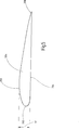
Der erste Fin ist erfindungsgemäß an einem ersten Ende in geeigneter Weise mit der Strömungsleitfläche verbunden, beziehungsweise an der Strömungsleitfläche befestigt. Beispielsweise kann der erste Fin an seinem ersten Ende mit der Strömungsleitfläche verschweißt oder angeflanscht sein. Das zweite Ende des ersten Fins ist erfindungsgemäß als freies Ende ausgebildet. Somit kann der erste Fin von der Strömungsleitfläche in jeder beliebigen Richtung vorstehen, wobei das zweite Ende des ersten Fins nicht mit der Strömungsleitfläche verbunden ist oder anderweitig am Schiffskörper befestigt ist. Unter dem Begriff „Fin” ist eine Leitflosse, beziehungsweise ein Tragflügel zu verstehen, der bevorzugterweise an der Strömungsleitfläche feststehend angeordnet ist. Dabei kann unter dem Begriff „Fin” grundsätzlich jede die Propellerzuströmung beeinflussende Leiteinrichtung verstanden werden, wobei der Fin in der Regel ein Tragflügelprofil aufweist, das heißt, eine Saug- und eine Druckseite umfasst. Somit sind Fins im vorliegenden Zusammenhang Strömungsleitflächen im Sinne von Statoren, die an der Strömungsleitfläche angeordnet sind und die Propellerzuströmung beeinflussen. Insbesondere ist es bevorzugt, dass die Fins eine, insbesondere kreisbogenförmig, nach außen gewölbte Saugseite und eine im Wesentlichen ebene Druckseite aufweisen.The first fin is inventively connected at a first end in a suitable manner with the flow guide, or attached to the flow guide. For example, the first fin may be welded or flanged to the flow guide at its first end. The second end of the first fin is formed according to the invention as a free end. Thus, the first fin may protrude from the flow guide in any direction, with the second end of the first fin not connected to the flow guide or otherwise attached to the hull. The term "fin" is understood to mean a fin, or a wing, which is preferably arranged fixedly on the flow guide surface. In this case, the term "fin" basically means any guide device influencing the propeller inflow, the fin generally having an airfoil profile, that is to say comprising a suction and a pressure side. Thus, in the present context, fins are flow-guiding surfaces in the sense of stators, which are arranged on the flow-guiding surface and influence the propeller inflow. In particular, it is preferable in that the fins have a suction side, in particular a circular arc, that is curved outward and a substantially flat pressure side.
Das Profil des ersten Fins kann über seine Länge betrachtet gleichmäßig oder auch unterschiedlich sein. Insbesondere kann das Profil entlang der Längsrichtung des ersten Fins betrachtet in sich gedreht, das heißt getwisted, sein. Somit dient der erste Fin zusätzlich zur Strömungsleitfläche ebenfalls als Leitfläche für die Wasserströmung, wobei die Strömungsleitfläche und der erste Fin in einem Winkel zueinander angeordnet sind und bevorzugterweise der erste Fin kleiner ausgebildet ist als die Strömungsleitfläche. Unter Länge des ersten Fins ist der Abstand zwischen dem ersten Ende und dem zweiten Ende des ersten Fins zu verstehen. Unter Tiefe des ersten Fins ist die Tiefe des Fins in Längsrichtung der Strömungsleitfläche, das heißt in Fahrtrichtung des Wasserfahrzeugs, zu verstehen. Die Dicke des Fins wird im Folgenden als Profildicke bezeichnet.The profile of the first fin may be uniform or even different over its length. In particular, viewed in the longitudinal direction of the first fin, the profile may be turned, ie twisted, in itself. Thus, the first fin in addition to the flow guide also serves as a guide surface for the water flow, wherein the flow guide and the first fin are arranged at an angle to each other and preferably the first fin is formed smaller than the flow guide. The length of the first fin means the distance between the first end and the second end of the first fin. Depth of the first fin is to be understood as meaning the depth of the fin in the longitudinal direction of the flow guidance surface, that is to say in the direction of travel of the watercraft. The thickness of the fin is referred to below as the profile thickness.
Unter erster Fin sind im Sinne der vorliegenden Erfindung alle Fins zu verstehen, welche von der Strömungsleitfläche vorstehen und mit einem ersten Ende mit der Strömungsleitfläche verbunden sind und deren zweites Ende als freies Ende ausgebildet ist. Bevorzugterweise können mehrere derartige erste Fins vorgesehen sein.For the purposes of the present invention, first fin means all fins which project from the flow guide surface and are connected at a first end to the flow guide surface and whose second end is designed as a free end. Preferably, a plurality of such first fins may be provided.
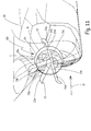
Bevorzugterweise ist die Strömungsleitfläche vor einem Propeller angeordnet. Dies bedeutet, dass die Strömungsleitfläche in Fahrtrichtung des Wasserfahrzeugs, beziehungsweise des Schiffs, vor einem Propeller des Wasserfahrzeugs angeordnet ist. Unter der Bezeichnung ”in Fahrtrichtung” ist hier die Vorwärtsfahrtrichtung eines Schiffes beziehungsweise eines Wasserfahrzeugs zu verstehen.Preferably, the flow guide is arranged in front of a propeller. This means that the flow guide in the direction of travel of the watercraft, or the ship, is arranged in front of a propeller of the watercraft. The term "in the direction of travel" here is to be understood as the forward direction of travel of a ship or a watercraft.
Dabei ist es ferner bevorzugt, dass die Strömungsleitfläche beabstandet zu dem Propeller angeordnet ist. Des Weiteren ist es bevorzugt, dass die Strömungsleitfläche beabstandet zu einem Wellenlager, insbesondere einem Stevenrohr, angeordnet ist. Ein Stevenrohr dient zur Lagerung einer Propellerwelle des Propellers des Wasserfahrzeugs beziehungsweise des Schiffs. Hierzu kann die Strömungsleitfläche zumindest bereichsweise oberhalb, unterhalb oder auch seitlich von der Propellerachse angeordnet sein. Ferner kann die Strömungsleitfläche die Propellerachse oder das Wellenlager zumindest teilweise umschließen. Besonders bevorzugterweise ist die Strömungsleitfläche bogenförmig oberhalb und beabstandet zur Propellerachse beziehungsweise zur Propellerwelle angeordnet. Dabei kann die bogenförmig ausgebildete Strömungsleitfläche in Umfangsrichtung auch geschlossen ausgebildet sein. Bevorzugterweise weist eine bogenförmige Strömungsleitfläche allerdings einen Querschnitt eines Achtel-Rings, eines Viertel-Rings auf. Ferner ist es bevorzugt, dass die Strömungsleitfläche einen Querschnitt eines halben Rings, eines Zweidrittel-Rings oder eines Dreiviertel-Rings aufweist.In this case, it is further preferred that the flow guide surface is arranged at a distance from the propeller. Furthermore, it is preferred that the flow guide surface is arranged at a distance from a shaft bearing, in particular a sterntube. A stern tube serves to support a propeller shaft of the propeller of the vessel or of the ship. For this purpose, the flow guide can be arranged at least partially above, below or even laterally from the propeller axis. Furthermore, the flow guide can at least partially enclose the propeller shaft or the shaft bearing. Particularly preferably, the flow guide is arcuately above and spaced from the propeller shaft or to the propeller shaft. In this case, the arc-shaped flow-guiding surface may also be designed to be closed in the circumferential direction. However, an arcuate flow guide surface preferably has a cross-section of an eighth-note ring, a quarter-ring. Furthermore, it is preferred that the flow guide surface has a cross-section of half a ring, a two-thirds ring or a three-quarter ring.
Ferner kann die Strömungsleitfläche bogenförmig und umfänglich offen ausgebildet sein, wobei die Strömungsleitfläche keinen kreisrunden Querschnitt, sondern beispielsweise einen ellipsenförmigen Querschnitt aufweist. Bevorzugt ist die Strömungsleitfläche konvex gegenüber der Propellerachse ausgebildet.Furthermore, the flow guide surface can be formed arcuate and circumferentially open, wherein the flow guide does not have a circular cross section, but for example, an elliptical cross section. Preferably, the flow guide surface is convex with respect to the propeller axis.
Bei einer bogenförmigen Ausbildung der Strömungsleitfläche ist die Bogenlänge der Strömungsleitfläche bei Querschnittsbetrachtung bevorzugt kleiner als 80%, besonders bevorzugt kleiner als 60%, ganz besonders bevorzugt kleiner als 40% oder 30% des Umfangs der gedanklich umfänglich geschlossenen Strömungsleitfläche.In the case of an arc-shaped design of the flow-guiding surface, the arc length of the flow-guiding surface is preferably less than 80%, particularly preferably less than 60%, very particularly preferably less than 40% or 30% of the circumference of the conceptually circumferentially closed flow-guiding surface.
Grundsätzlich sind aber auch andere Querschnitte denkbar. Beispielsweise könnte die Strömungsleitfläche einen eckigen, beispielsweise einen rechteckigen Querschnitt aufweisen. Ferner wäre eine U-förmige Ausgestaltung der Strömungsleitfläche denkbar.In principle, however, other cross sections are conceivable. For example, the flow guide could have a square, for example, a rectangular cross-section. Furthermore, a U-shaped configuration of the flow guide would be conceivable.
Durch die Anordnung eines ersten Fins an der Strömungsleitfläche, wobei ein erstes Ende des ersten Fins an der Strömungsleitfläche befestigt ist und ein zweites Ende des ersten Fins als freies Ende ausgebildet ist, kann erreicht werden, dass die Abmessungen, beispielsweise die Länge oder die Breite beziehungsweise die Bogenlänge und/oder die Profildicke der Strömungsleitfläche gegenüber den aus dem Stand der Technik bekannten Vorrichtungen deutlich reduziert werden kann, wobei durch den ersten Fin trotzdem noch diejenigen Bereiche erreicht werden können, in denen die Strömungsverluste besonders hoch sind und in denen ein Vordrall für einen effizienten Betrieb erzeugt werden muss.By arranging a first fin on the flow guide surface, wherein a first end of the first fin is attached to the flow guide surface and a second end of the first fins is formed as a free end, it can be achieved that the dimensions, for example, the length or the width or the arc length and / or the profile thickness of the flow guide over the known from the prior art devices can be significantly reduced, yet those areas can still be achieved by the first fin in which the flow losses are particularly high and in which a pre-twist for a efficient operation must be generated.
Außerdem ist es bevorzugt, dass das zweite Ende des ersten Fins ausgehend von der Strömungsleitfläche von der Propellerachse weg gerichtet ist. Das heißt, dass der Abstand von dem ersten Ende des ersten Fins zur Propellerachse kleiner ist als der Abstand von dem zweiten Ende (freien Ende) des ersten Fins zur Propellerachse.In addition, it is preferred that the second end of the first fin is directed away from the propeller axis, starting from the flow guide surface. That is, the distance from the first end of the first fin to the propeller axis is less than the distance from the second end (free end) of the first fin to the propeller axis.
Somit kann die Strömungsleitfläche beabstandet zur Propellerwelle angeordnet sein, wobei im Gegensatz zum Stand der Technik der Abstand zwischen Propellerwelle und der Strömungsleitfläche geringer ist. Dadurch, dass der erste Fin von der Strömungsleitfläche derart hervorsteht, dass sein zweites Ende von der Propellerachse weggerichtet ist, ist weiterhin sichergestellt, dass der erste Fin weit genug von der Propellerwelle wegreicht (in Radialrichtung von der Propellerwelle aus gesehen) und somit weiterhin die Zuströmung auf den jeweils zugeordneten Propeller positiv beeinflussen kann.Thus, the flow guide can be arranged spaced from the propeller shaft, wherein, in contrast to the prior art, the distance between the propeller shaft and the flow guide is smaller. Characterized in that the first fin of the flow guide protrudes such that its second end is directed away from the propeller axis, it is further ensured that the first fin far enough away from the propeller shaft (seen in the radial direction of the propeller shaft) and thus Furthermore, the inflow to the respective associated propeller can positively influence.
Durch die Anbringung eines Fins an der Strömungsleitfläche kann somit der Abstand von der Strömungsleitfläche zur Propellerwelle sowie auch die Profildicke der Strömungsleitfläche und damit der Widerstand verringert werden, so dass die Vorrichtung nunmehr auch für schnelle und sehr schnelle Schiffe anwendbar ist, wobei die positiven Wirkungen für die Verringerung des Antriebsleistungsbedarfs erhalten bleiben beziehungsweise gegebenenfalls sogar noch verbessert werden. Dadurch, dass der erste Fin von der Strömungsleitfläche nach außen vorsteht und nicht etwa von der Propellernabe beziehungsweise dem Stevenrohr, kann dieser relativ weit nach außen von der Propellerachse aus gesehen reichen und trotzdem noch eine ausreichende Festigkeit, insbesondere in Bezug auf Biegebeanspruchungen, aufweisen.By attaching a fin on the flow guide thus the distance from the flow guide to the propeller shaft and the profile thickness of the Strömungsleitfläche and thus the resistance can be reduced, so that the device is now applicable to fast and very fast ships, the positive effects for the reduction of the drive power requirement is maintained or possibly even improved. Due to the fact that the first fin projects outward from the flow guide surface and not from the propeller hub or sterntube, it can extend relatively far outward from the propeller axis and still have sufficient strength, in particular with respect to bending stresses.
Bevorzugterweise weist der erste Fin eine größte Profildicke auf, wobei diese größte Profildicke des ersten Fins weniger als 50%, besonders bevorzugterweise weniger als 25%, sowie ganz besonders bevorzugterweise weniger als 15% des Abstandes zwischen dem ersten Ende und dem zweiten Ende des ersten Fins beträgt. Somit ist die Profildicke des ersten Fins an dessen dickster Stelle geringer als die Länge des ersten Fins zwischen seinem ersten Ende und seinem zweiten Ende.Preferably, the first fin has a largest profile thickness, wherein this largest profile thickness of the first fin is less than 50%, more preferably less than 25%, and most preferably less than 15% of the distance between the first end and the second end of the first fin is. Thus, the profile thickness of the first fin at its thickest point is less than the length of the first fin between its first end and its second end.
Grundsätzlich kann die Strömungsleitfläche im parallel zur Propellerachse beziehungsweise parallel zur Propellerwelle angeordnet sein. Dies bedeutet, dass der Abstand zwischen Strömungsleitfläche und Propellerachse in jedem Bereich im Wesentlichen gleich ist. Bevorzugterweise ist die Strömungsleitfläche aber nach hinten oder nach vorne zur Propellerachse hin geneigt angeordnet. Dabei ist die Strömungsleitfläche bevorzugterweise profiliert ausgebildet. Somit weist die Strömungsleitfläche eine Profileintrittskante, welche vom Propeller weggerichtet ist und auf die die Wasserströmung bei Fahrtrichtung des Wasserfahrzeugs in Vorwärtsfahrtrichtung auftritt, auf. Die Profilaustrittskante der Strömungsleitfläche ist zum Propeller hin gerichtet. Bei der Profileintrittskante und der Profilaustrittskante handelt es sich somit um die beiden stirnseitigen Kanten der Strömungsleitfläche. Bei einer nach hinten zur Propellerachse geneigt angeordneten Strömungsleitfläche ist somit der Abstand zwischen Propellerachse und Strömungsleitfläche im Bereich der Profileintrittskante größer als im Bereich der Profilaustrittskante. Durch eine derart geneigte Anordnung der Strömungsleitfläche kann die Zuströmung auf den Propeller in bestimmten Bereichen besonders vorteilhaft beeinflusst werden. Bei einer zur Propellerachse hin geneigt angeordneten Strömungsleitfläche verläuft die Längsachse der Strömungsleitfläche somit nicht parallel zur Propellerachse sondern in einem Winkel und ist dadurch im Bezug auf die Propellerachse schräg gestellt.In principle, the flow guide surface can be arranged parallel to the propeller axis or parallel to the propeller shaft. This means that the distance between the flow guide surface and the propeller axis in each region is substantially the same. Preferably, however, the flow guide surface is arranged inclined backwards or forwards towards the propeller axis. In this case, the flow guide surface is preferably formed profiled. Thus, the flow guide has a profile leading edge, which is directed away from the propeller and on the water flow in the direction of travel of the watercraft occurs in the forward direction on. The profile outlet edge of the flow guide is directed towards the propeller. The profile entry edge and the profile exit edge are thus the two end edges of the flow guide surface. In the case of a flow guide surface which is inclined towards the rear of the propeller axis, the distance between the propeller axis and the flow guide surface in the region of the profile entry edge is thus greater than in the region of the profile exit edge. By such an inclined arrangement of the flow guide surface, the inflow to the propeller in certain areas can be influenced particularly advantageously. In a propeller axis inclined towards arranged flow guide the longitudinal axis of the flow guide thus does not run parallel to the propeller axis but at an angle and is thereby inclined with respect to the propeller axis.
Vorzugsweise ist der kürzeste Abstand zwischen Strömungsleitfläche und Propellerachse kleiner als die Hälfte des Propellerdurchmessers, beziehungsweise kleiner als der Radius des Propellers. Bei einer nach hinten zur Propellerachse geneigt angeordneten Strömungsleitfläche ist somit der Abstand zwischen Strömungsleitfläche und Propellerachse im Bereich der Profilaustrittskante der Strömungsleitfläche kürzer als die Hälfte des Propellerdurchmessers.Preferably, the shortest distance between the flow guide surface and the propeller axis is smaller than half the diameter of the propeller, or smaller than the radius of the propeller. In the case of a flow guide surface arranged at an angle to the rear of the propeller axis, the distance between the flow guide surface and the propeller axis in the region of the profile outlet edge of the flow guide surface is shorter than half of the propeller diameter.
Vorzugsweise ist ferner mindestens ein zweiter Fin vorgesehen, welcher von der Strömungsleitfläche vorsteht. Dabei ist der zweite Fin mit seinem ersten Ende an der Strömungsleitfläche angeordnet, beziehungsweise an dieser befestigt und mit seinem zweiten Ende an einem Wellenlager, insbesondere Stevenrohr, angeordnet, beziehungsweise befestigt. Somit ist der zweite Fin ausgehend von der Strömungsleitfläche zur Propellerachse hingerichtet, und weist im Gegensatz zum ersten Fin kein freies Ende auf, sondern ist mit dem Schiffskörper oder dem Wellenlager verbunden. Somit verläuft der zweite Fin zwischen zwei festen Lagerpunkten vom Wellenlager bis zur Strömungsleitfläche. Zwischen den beiden Enden weist der zweite Fin vorzugsweise eine Druckseite, eine Saugseite, eine Nasenleiste und eine Endleiste auf. Diese Ausbildung gilt auch analog für den ersten Fin, welcher mit einem freien Ende von der Strömungsleitfläche nach außen vorsteht. Je nach Gestaltung des Schiffskörpers kann der zweite Fin anstatt an einem Wellenlager auch direkt am Schiffskörper beziehungsweise an der Beplattung des Schiffskörpers mit seinem zweiten Ende angebracht sein.Preferably, at least one second fin is further provided, which protrudes from the flow guide. In this case, the second fin is arranged with its first end to the flow guide, or attached thereto and arranged with its second end to a shaft bearing, in particular sterntube, or fixed. Thus, the second fin is executed starting from the flow guide to the propeller axis, and in contrast to the first fin no free end, but is connected to the hull or the shaft bearing. Thus, the second fin extends between two fixed bearing points from the shaft bearing to the flow guide. Between the two ends, the second fin preferably has a pressure side, a suction side, a leading edge and an end strip. This design also applies analogously to the first fin, which protrudes with a free end of the flow guide to the outside. Depending on the design of the hull of the second fin may be mounted instead of a shaft bearing directly on the hull or on the plating of the hull with its second end.
Unter ”zweiten Fin” sind im Sinne der vorliegenden Erfindung sämtliche Fins zu verstehen, welche von der Strömungsleitfläche vorstehen und mit ihrem ersten Ende mit der Strömungsleitfläche verbunden sind, sowie mit ihrem zweiten Ende mit dem Wellenlager oder dem Schiffskörper verbunden sind. Bevorzugterweise können mehrere derartige zweite Fins vorgesehen sein.For the purposes of the present invention, "second fin" means all fins which project from the flow guide surface and are connected at their first end to the flow guide surface, and are connected at their second end to the shaft bearing or the hull. Preferably, a plurality of such second fins may be provided.
Ferner ist es zweckmäßig, dass der erste Fin und/oder der zweite Fin im Wesentlichen in Radialrichtung zur Längsachse der Strömungsleitfläche oder zur Propellerachse eines Antriebspropellers eines Wasserfahrzeugs angeordnet sind. Vorzugsweise sind beide Fins, der erste und auch der zweite Fin, in Radialrichtung angeordnet. Grundsätzlich könnten der erste Fin sowie auch der zweite Fin unter unterschiedlichen Winkeln zu ihren jeweiligen Tangenten angeordnet sein. Die Tangente für den ersten Fin läuft durch einen Punkt an der äußeren Wandfläche der Strömungsleitfläche, während die Tangente für den zweiten Fin durch einen Punkt der inneren Wandfläche der Strömungsleitfläche verläuft. Unter äußerer Wandfläche der Strömungsleitfläche ist die von der Propellerachse beziehungsweise Propellerwelle weg gerichtete Wandfläche zu verstehen. Dagegen ist unter innerer Wandfläche die Wandfläche der Strömungsleitfläche zu verstehen, welche zur Propellerachse, beziehungsweise zur Propellerwelle hingerichtet ist.Furthermore, it is expedient that the first fin and / or the second fin are arranged essentially in the radial direction to the longitudinal axis of the flow guide surface or to the propeller axis of a drive propeller of a watercraft. Preferably, both fins, the first and the second fin, are arranged in the radial direction. In principle, the first fin as well as the second fin could be arranged at different angles to their respective tangents. The tangent for the first fin passes through a point on the outer wall surface of the flow guide surface, while the tangent for the second fin passes through a point of the flow guide surface inner wall surface of the flow guide extends. The outer wall surface of the flow guide surface is to be understood as the wall surface directed away from the propeller shaft or propeller shaft. In contrast, internal wall surface is to be understood as the wall surface of the flow guide surface which is executed to the propeller shaft or to the propeller shaft.
Ferner ist bevorzugt, dass die Ausdehnung der einzelnen Fins (erster Fin sowie auch zweiter Fin) in Längsrichtung der Strömungsleitfläche kleiner, beziehungsweise kürzer, als die Länge der Strömungsleitfläche ist. Unter „Ausdehnung” ist dabei der Bereich beziehungsweise die Länge des Längsprofils der Strömungsleitfläche zu verstehen, über die sich die Fins in Strömungsleitflächenlängsrichtung strecken. Besonders bevorzugt ist die Ausdehnung der einzelnen Fins in Längsrichtung der Strömungsleitfläche kleiner als 90%, ganz besonders bevorzugt kleiner als 80% oder auch kleiner als 60% der Länge der Strömungsleitfläche. Die Längsrichtung entspricht im Wesentlichen der Strömungsrichtung. Weiterhin ist es bevorzugt, dass die Fins im Wesentlichen im hinteren Bereich, das heißt, in dem Propeller zugewandten Bereich, der Strömungsleitfläche angeordnet sind. Grundsätzlich wäre jedoch auch eine Ausbildung der Fins über die gesamte Ausdehnung der Strömungsleitfläche in Längsrichtung oder auch eine mittige oder vordere Anordnung der Fins in Bezug auf die Fahrtrichtung möglich.It is further preferred that the extent of the individual fins (first fin as well as second fin) in the longitudinal direction of the flow guide surface is smaller or shorter than the length of the flow guide surface. "Expansion" is to be understood as meaning the region or the length of the longitudinal profile of the flow-guiding surface over which the fins extend in the flow-guiding surface longitudinal direction. Particularly preferably, the expansion of the individual fins in the longitudinal direction of the flow guide surface is less than 90%, very particularly preferably less than 80% or even less than 60% of the length of the flow guide surface. The longitudinal direction substantially corresponds to the flow direction. Furthermore, it is preferred that the fins are arranged substantially in the rear region, that is, in the region facing the propeller, the flow guide surface. In principle, however, a formation of the fins over the entire extent of the flow guide in the longitudinal direction or a central or front arrangement of the fins with respect to the direction of travel would be possible.
Die jeweiligen beiden ersten Enden des ersten und des zweiten Fins sind an der Strömungsleitfläche befestigt. Vorteilhafterweise kann das erste Ende des ersten Fins entweder an der äußeren Wandfläche der Strömungsleitfläche befestigt sein, beispielsweise durch Anflanschen oder auch in das Strömungsleitflächenprofil, das heißt, die Wand der Strömungsleitfläche, hineingeführt sein. Alternativ ist auch eine Durchführung des ersten Fins durch das Leitflächenprofil beziehungsweise die Strömungsleitfläche möglich. Das erste Ende des ersten Fins bildet somit die Wurzel des ersten Fins und das zweite Ende bildet die Spitze des ersten Fins.The respective two first ends of the first and second fins are attached to the flow guide surface. Advantageously, the first end of the first fins can either be fastened to the outer wall surface of the flow guide surface, for example by flanging or in the flow guide profile, that is to say the wall of the flow guide surface. Alternatively, a passage of the first fins through the baffle profile or the flow guide is possible. The first end of the first fin thus forms the root of the first fin and the second end forms the tip of the first fin.
Sämtliche beschriebenen Ausgestaltungsmöglichkeiten für den ersten Fin sind analog auch für die Ausgestaltung des zweiten Fins und umgekehrt übertragbar beziehungsweise dort anwendbar.All described design options for the first fin are analogous to the design of the second fin and vice versa transferable or applicable there.
Die Strömungsleitfläche kann bevorzugt über den zweiten Fin mit dem Schiffskörper verbunden sein. Zusätzlich oder alternativ kann die Strömungsleitfläche auch über weitere Verbindungsmittel, beispielsweise unterhalb oder oberhalb der Strömungsleitfläche angeordnete „Brackets” beziehungsweise Halteklammern oder auch Wellenbockarme, mit dem Schiffskörper verbunden sein. Die Wellenbockarme könnten, zumindest bereichsweise, ebenfalls als Fins ausgebildet sein.The flow guide surface can preferably be connected to the hull via the second fin. In addition or as an alternative, the flow guide surface can also be connected to the hull via other connecting means, for example "brackets" or holding clamps or else shaft bracket arms arranged below or above the flow guide surface. The Wellenbockarme could, at least partially, also be designed as Fins.
In einer bevorzugten Ausführungsform sind mehrere erste und zweite Fins vorgesehen. Dies bedeutet, dass mehrere Fins vorgesehen sind, welche von der Strömungsleitfläche derart nach außen vorstehen, dass sie mit ihrem jeweiligen ersten Ende mit der Strömungsleitfläche verbunden sind und mit ihrem jeweiligen zweiten Ende frei stehend angeordnet sind. Ferner sind mehrere Fins vorgesehen, welche mit ihrem ersten Ende mit der Strömungsleitfläche verbunden sind und mit ihrem zweiten Ende mit dem Schiffskörper oder der Propellerwelle verbunden sind. Insbesondere ist es bevorzugt, dass eine gleiche Anzahl von ersten Fins und von zweiten Fins vorgesehen ist. Grundsätzlich wäre aber auch die Vorsehung einer ungleichen Anzahl von ersten und zweiten Fins möglich.In a preferred embodiment, a plurality of first and second fins are provided. This means that a plurality of fins are provided which project outward from the flow guide surface such that they are connected with their respective first end to the flow guide surface and are arranged freely with their respective second end. Further, a plurality of fins are provided, which are connected at their first end to the flow guide and are connected at their second end to the hull or the propeller shaft. In particular, it is preferred that an equal number of first fins and second fins is provided. In principle, however, the providence of an unequal number of first and second fins would be possible.
Es ist besonders bevorzugt, dass die Vorrichtung mindestens drei erste Fins und/oder mindestens drei zweite Fins, bevorzugt drei bis sieben erste Fins und/oder drei bis sieben zweite Fins, aufweist. Auch kann in einer bevorzugten Ausführungsform eine ungerade Anzahl von ersten Fins und/oder zweiten Fins vorgesehen sein.It is particularly preferred that the device has at least three first fins and / or at least three second fins, preferably three to seven first fins and / or three to seven second fins. Also, in a preferred embodiment, an odd number of first fins and / or second fins may be provided.
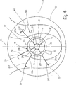
Ferner ist es bevorzugt, dass auf der propelleraufschlagenden Seite der Strömungsleitfläche mehr erste Fins als auf der propellerabschlagenden Seite der Strömungsleitfläche angeordnet sind, und/oder dass auf der propelleraufschlagenden Seite der Strömungsleitfläche mehr zweite Fins angeordnet sind als auf der propellerabschlagenden Seite der Strömungsleitfläche. Unter dem Begriff „propelleraufschlagende Seite der Strömungsleitfläche” wird diejenige Seite der Strömungsleitfläche verstanden, auf der der von einer Frontalansicht der Strömungsleitfläche hinter der Strömungsleitfläche angeordnete Propeller bei Vorwärtsfahrt von unten nach oben dreht. Entsprechend dreht der Propeller bei der propellerabschlagenden Seite von oben nach unten. Daher ist die vorliegend beschriebene Ausführungsform besonders zweckmäßig einsetzbar bei Strömungsleitflächen, deren mittlere Längsachse gegenüber der Propellerachse nicht seitlich verschoben ist, sondern vielmehr in einer vertikal auf der Propellerachse stehenden Ebene liegt, sodass bei gedachter Teilung der Strömungsleitfläche in zwei Strömungsleitflächenhälften durch eine mittige Vertikalachse eine Hälfte der Strömungsleitfläche auf der propelleraufschlagenden Seite und die andere Hälfte auf der propellerabschlagenden Seite liegt.Further, it is preferred that on the propeller-facing side of the flow guide more first fins than on the propeller abschlagenden side of the flow guide are arranged, and / or that on the propelleraufschlagenden side of the Strömungsleitfläche more second fins are arranged as on the propellerabschlagenden side of the flow guide. The term "propeller-impacting side of the flow-guiding surface" is understood to mean that side of the flow-guiding surface on which the propeller arranged from a frontal view of the flow-guiding surface behind the flow-guiding surface rotates from the bottom to the top during forward travel. Accordingly, the propeller turns at the propeller off-striking side from top to bottom. Therefore, the presently described embodiment is particularly useful for flow control surfaces whose central longitudinal axis relative to the propeller axis is not laterally displaced, but rather in a vertical plane on the propeller axis, so at an imaginary division of the flow in two Strömungsleitflächenhälften by a central vertical axis one half the flow guide surface lies on the propeller-impacting side and the other half lies on the propeller-deflecting side.
Um die Rotationsverluste am Propeller zu minimieren und um die durch die von der Hülle des Schiffs gestörte Propelleranströmung induzierte Verdrillung im Propellerabstrom zu reduzieren, wird durch die an der Strömungsleitfläche angeordneten Fins (erste Fins oder zweite Fins) ein (Vor-)Drall erzeugt, der derart ausgerichtet ist, dass sich hinter dem Propeller im Propellerabstrombereich im Vergleich zu einem Propeller ohne vorangestellte Strömungsleitfläche mit Fins eine geringere Verdrillung der Strömung einstellt. Die Verdrillung im Propellerabstrom ist nunmehr besonders gering, wenn auf der propelleraufschlagenden Seite des Propellers wenigstens ein erster Fin und/oder ein zweiter Fin mehr angeordnet ist, als auf der propellerabschlagenden Seite.In order to minimize the rotational losses on the propeller and to reduce the induced in the Propellerabstrom by the impeller flow disturbed by the shell of the ship, is arranged by the on the flow guide Fins (first fins or second fins) produces a (pre-) spin that is oriented so that sets behind the propeller in Propellerabstrombereich compared to a propeller without prefixed flow guide with fins a lower twist of the flow. The twist in the propeller effluent is now particularly low if at least one first fin and / or a second fin is arranged more on the propeller-impacting side of the propeller than on the propeller-deflecting side.
Alternativ oder zusätzlich zur Verteilung der ersten und/oder zweiten Fins auf der propelleraufschlagenden und propellerabschlagenden Seite können die ersten Fins und/oder die zweiten Fins ein asymmetrisches erstes Fin-System beziehungsweise ein asymmetrisches zweitens Fin-System bilden. Hierbei bezieht sich eine Asymmetrie beispielsweise auf eine bezüglich der Propellerachse gerichtete Winkelanordnung der Fins und/oder deren Dimensionierung, wie Länge, Profilquerschnitt oder eine andere Größe. Bei einer Asymmetrie bezüglich der auf die Propellerachse gerichteten Winkelanordnung stellt sich eine ungleiche Winkelteilung zwischen den Achsen der einzelnen ersten Fins und/oder zweiten Fins in Radialrichtung von der Propellerachse betrachtet ein. Auch kann eine asymmetrische Anordnung vorliegen, wenn die vertikale Mittelachse der Strömungsleitfläche als Symmetrieachse herangezogen wird. Diese Symmetrieachse trennt in der Regel gleichzeitig die auf- und abschlagende Seite der Strömungsleitfläche. Hierdurch ergibt sich auf einfach auszubildende und abzuordnende Art und Weise ein besonders wirksames erstes Fin-System beziehungsweise zweites Fin-System.As an alternative or in addition to the distribution of the first and / or second fins on the propeller-impacting and propeller-deflecting side, the first fins and / or the second fins can form an asymmetrical first fin system or an asymmetric second fin system. In this case, an asymmetry relates, for example, to an angular arrangement of the fins directed with respect to the propeller axis and / or their dimensioning, such as length, profile cross-section or another size. In an asymmetry with respect to the angular arrangement directed towards the propeller axis, an unequal angular separation between the axes of the individual first fins and / or second fins in the radial direction as viewed from the propeller axis arises. An asymmetric arrangement may also be present if the vertical center axis of the flow guide surface is used as the axis of symmetry. As a rule, this symmetry axis simultaneously separates the up-and-down side of the flow guide surface. As a result, a particularly effective first fin system or second fin system results in a manner which is easy to form and to be rejected.
In einer weiteren bevorzugten Ausführungsform ist der mindestens eine erste Fin in Verlängerung des mindestens einen zweiten Fins angeordnet, so dass beide zusammen einen Gesamt-Fin bilden. So können beispielsweise die Längsachsen des ersten Fins und des zweiten Fins im Wesentlichen aufeinanderstehen und/oder der erste Fin und der zweite Fin auf einer gemeinsamen Radialachse angeordnet sein. Bevorzugt ist das erste Ende des zweiten Fins, welches zweckmäßigerweise an der Innenwandfläche der Strömungsleitfläche angeordnet ist, gegenüberliegend zum ersten Ende des ersten Fins angeordnet, der an der Außenwandfläche der Strömungsleitfläche angeordnet ist, so dass dann nur noch die Strömungsleitfläche zwischen den beiden Fins liegt. Grundsätzlich könnten auch beide Endbereiche jeweils in das Profil der Strömungsleitfläche beziehungsweise in die Strömungsleitfläche eingeführt werden, sodass diese dann gegebenenfalls aneinanderstoßen oder nur noch geringfügig voneinander beabstandet sind. Auch ist es möglich, einen durchgehenden Fin zu verwenden, der durch eine Ausnehmung in der Strömungsleitfläche hindurchgeführt wird und an dem ein Teilabschnitt einen ersten Fin und ein anderer Teilabschnitt einen zweiten Fin bildet. Durch diese bevorzugte Anordnung der beiden Fins ergibt sich strömungstechnisch ein einzelner Fin, der zweckmäßigerweise vom Wellenlager bis zum freien Ende des ersten Fins verläuft. Sind mehrere erste Fins und zweite Fins, insbesondere eine gleiche Anzahl von ersten Fins und zweiten Fins, vorgesehen, sind diese vorteilhafterweise jeweils in Fin-Paaren angeordnet, die dann jeweils Gesamt-Fins bilden. So könnten beispielsweise drei erste Fins und drei zweite Fins zusammen drei Gesamt-Fins bilden.In a further preferred embodiment, the at least one first fin is arranged in extension of the at least one second fin, so that together they form an overall fin. Thus, for example, the longitudinal axes of the first fin and the second fin may be substantially on one another and / or the first fin and the second fin may be arranged on a common radial axis. Preferably, the first end of the second fin, which is expediently arranged on the inner wall surface of the flow guide, arranged opposite to the first end of the first fin, which is arranged on the outer wall surface of the flow guide surface, so that then only the flow guide surface between the two fins is located. In principle, both end regions could each be introduced into the profile of the flow guide surface or into the flow guide surface, so that they then abut one another, if necessary, or are only slightly spaced apart from one another. It is also possible to use a continuous fin which is passed through a recess in the flow guide surface and on which one section forms a first fin and another section forms a second fin. This preferred arrangement of the two fins results in fluidically a single fin, which expediently extends from the shaft bearing to the free end of the first fin. If a plurality of first fins and second fins, in particular an equal number of first fins and second fins, are provided, these are advantageously arranged in each case in fin pairs, which then each form overall fins. For example, three first fins and three second fins could together make up three total fins.
Im Vergleich zum aus dem Stand der Technik bekannten, reinen Statoranordnungen, beziehungsweise Anordnungen mit radial vom Stevenrohr abstehenden Fins ohne Strömungsleitfläche ergibt sich durch das Vorsehen der Strömungsleitfläche eine deutliche erhöhte Festigkeit der gesamten Anordnung. Hierdurch können die Gesamt-Fins bei einer sichergestellten Dauerfestigkeit ausreichend lang ausgeführt werden, um die Anströmung auf den Propeller optimal zu beeinflussen beziehungsweise einen möglichst optimalen Wirkungsgrad zu erreichen. Bei aus dem Stand der Technik bekannten Anordnungen mit langen Fins ohne Strömungsleitfläche ist eine Dauerfestigkeit häufig nicht gewährleistet.Compared to the known from the prior art, pure stator assemblies, or arrangements with radially projecting from the stern tube fins without flow guide results in the provision of the Strömungsleitfläche a significant increased strength of the entire arrangement. As a result, the total fins can be made sufficiently long with a ensured fatigue strength to optimally influence the flow to the propeller or to achieve the best possible efficiency. In known from the prior art arrangements with long fins without flow control fatigue resistance is often not guaranteed.
Die Länge des Gesamt-Fins kann grundsätzlich größer oder kleiner als der Radius eines Propellers des Wasserfahrzeuges sein. Die Länge des Gesamt-Fins wird von der Propellerachse bis zum äußersten (freien) Ende des ersten Fins gemessen, wobei gegebenenfalls die zwischen beiden Fins (erster und zweiter Fin) angeordnete Strömungsleitfläche mit eingerechnet wird. Bevorzugt beträgt die Länge des Gesamt-Fins maximal 90% des Radius des Propellers, besonders bevorzugt maximal nur 75%. Jedoch wird eine ausreichende Festigkeit der Vorrichtung sichergestellt.The length of the total fin may be generally greater or smaller than the radius of a propeller of the watercraft. The length of the total fin is measured from the propeller axis to the outermost (free) end of the first fin, optionally including the flow guide area arranged between both fins (first and second fin). Preferably, the length of the total fins is at most 90% of the radius of the propeller, more preferably at most only 75%. However, sufficient strength of the device is ensured.
In einer weiteren bevorzugten Ausführungsform sind der erste Fin und/oder der zweite Fin unter einem Anstellwinkel radial zur Propellerachse angeordnet. Insbesondere können der erste Fin und der zweite Fin unterschiedliche Anstellwinkel aufweisen. Sind mehrere erste Fins und/oder zweite Fins vorgesehen, können diese untereinander auch unterschiedliche Anstellwinkel aufweisen. Durch die Einstellung der unterschiedlichen Anstellwinkel ist eine Optimierung des Vordralles möglich. Der Einstellwinkel wird beispielsweise von einer von der Nasenleiste zur Endleiste des jeweiligen Fins verlaufenden Sehne oder auch der Längsachse des Fins in Querschnittsansicht und der Propellerachse eingeschlossen.In a further preferred embodiment, the first fin and / or the second fin are arranged at an angle of attack radially to the propeller axis. In particular, the first fin and the second fin may have different angles of incidence. If a plurality of first fins and / or second fins are provided, they can also have different angles of incidence with one another. By adjusting the different angles of attack it is possible to optimize the pre-twist. The setting angle is enclosed, for example, by a chord running from the leading edge to the end line of the respective fin or also the longitudinal axis of the fin in cross-sectional view and the propeller axis.
In einer weiteren bevorzugten Ausführungsform weist der erste Fin ein freies Ende auf, welches den am entferntesten angeordneten Bereich des ersten Fins von der Strömungsleitfläche darstellt. An diesem freien Endbereich steht ein Fin-Endstück vom ersten Fin ab. So kann beispielsweise eine Längsachse dieses Fin-Endstückes unter einem Winkel zur Längsachse des ersten Fins stehen. Mit dem Begriff „abstehenden Fin-Endstück” sind vorliegend grundsätzlich alle im Bereich des freien Endes des ersten Fins angeordneten Bauteile gemeint, die nicht genau in der Verlängerung des ersten Fins angeordnet sind, sondern schräg vom ersten Fin beziehungsweise unter einem bestimmten Winkel vom ersten Fin abstehen, beziehungsweise von der fiktiv verlängerten Profilkontur des ersten Fins abweichen. Das Fin-Endstück steht somit aus der Fin-Ebene hervor. Ein solches abstehendes Fin-Endstück wirkt ähnlich wie von Flugzeugtragflügeln bekannte „Winglets” und verringert die Wahrscheinlichkeit von sich ablösenden Wirbeln im Endbereich des ersten Fins sowie von im selbigen auftretender Gravitation.In a further preferred embodiment, the first fin has a free end which represents the remainder of the region of the first fins of the flow guide. At This free end is a fin-tail from the first fin. For example, a longitudinal axis of this fin tail may be at an angle to the longitudinal axis of the first fin. The term "projecting fin-end piece" in this case basically all arranged in the region of the free end of the first fin components meant not exactly in the extension of the first fin are arranged, but obliquely from the first fin or at a certain angle from the first fin stand, or deviate from the fictitious extended profile contour of the first fin. The fin tail thus stands out from the fin plane. Such a projecting fin tail acts similarly to "winglets" known from aircraft wings and reduces the likelihood of detaching vertebrae in the end region of the first fin as well as gravitational forces occurring in the same.
Das Fin-Endstück kann unter einem Radius in den freien Endbereich des ersten Fins übergeben. Alternativ kann das Fin-Endstück auch unter einem Winkel am freien Ende des ersten Fins angebracht sein, sodass dann die Fin-Endstückebene und die Ebene über die sich der erste Fin erstreckt unter diesem Winkel aufeinanderstehen.The fin tail can be passed under a radius in the free end of the first fin. Alternatively, the fin tail may also be mounted at an angle at the free end of the first fin, so that then the fin end plane and the plane over which the first fin extends at this angle to each other.
Grundsätzlich kann das Fin-Endstück zu beiden Seiten, das heißt, sowohl zur Druck- als auch zur Saugseite, des ersten Fins von diesem abstehen oder nur zu einer der beiden Seiten. Bei letzterer Ausführungsform ist es bevorzugt, dass das Fin-Endstück nur zur Saugseite des ersten Fins hin absteht, da hierdurch die größeren hydrodynamischen Effekte in Bezug auf die Verringerung der Wirbelbildung erreicht werden können. Für die Ausführungsform, bei der das Fin-Endstück zu beiden Seiten des ersten Fins absteht beziehungsweise vorsteht, können auch zwei separate Fin-Endstücke vorgesehen sein, die dann jeweils zu einer Seite abstehen. Grundsätzlich ist aber auch bei dieser Ausführungsform eine einstückige Ausführung des Fin-Endstückes möglich.Basically, the fin-end piece on both sides, that is, to both the pressure and the suction side, the first fins of this protrude or only to one of the two sides. In the latter embodiment, it is preferable that the fin tail protrudes only toward the suction side of the first fin, since it can achieve the greater hydrodynamic effects with respect to the reduction of vortex formation. For the embodiment in which the fin-end piece protrudes or protrudes on both sides of the first fin, two separate fin-end pieces can be provided, which then each protrude to one side. In principle, however, a one-piece design of the fin-end piece is also possible in this embodiment.
Weiterhin ist es bevorzugt, dass bei Vorhandensein von mindestens einem ersten Fin und einem zweiten Fin, der erste Fin eine größere Länge aufweist als der zweite Fin. Insbesondere kann die Länge des ersten Fins mindestens eineinhalbmal, bevorzugt mindestens zweimal so groß sein, wie die Länge des zweiten Fins. Durch diese Ausführungsform wird eine verbesserte Wirkung in Bezug auf die Antriebsleistungsverringerung und in Bezug auf die Stabilität der Vorrichtung erhalten. Durch die Längenverteilung bei dieser bevorzugten Ausführungsform ist die Strömungsleitfläche relativ nah am Wellenlager der Propellerwelle angeordnet, sodass die Vorrichtung einen relativ geringen Widerstand aufweist und auch für sehr schnelle Schiffe verwendbar ist. Grundsätzlich ist jedoch auch eine Ausführung möglich, bei der der zweite Fin eine größere Länge aufweist, als der erste Fin, zum Beispiel eine mindestens eineinhalbfache oder mindestens zweifache Länge, oder bei der beide Fins einen in etwa gleiche Länge aufweisen.Furthermore, it is preferred that in the presence of at least a first fin and a second fin, the first fin has a greater length than the second fin. In particular, the length of the first fin may be at least one and a half times, preferably at least twice as long as the length of the second fin. By this embodiment, an improved effect in terms of drive power reduction and with respect to the stability of the device is obtained. Due to the length distribution in this preferred embodiment, the flow guide is arranged relatively close to the shaft bearing of the propeller shaft, so that the device has a relatively low resistance and is also suitable for very fast ships. In principle, however, an embodiment is possible in which the second fin has a greater length than the first fin, for example at least one and a half times or at least twice the length, or in which both fins have an approximately equal length.
Zur Sicherstellung eines ausreichend geringen Widerstandes der Vorrichtung kann gemäß einer weiteren Ausführungsform vorgesehen sein, dass die Profildicke der Strömungsleitfläche nicht mehr als 10%, bevorzugt nicht mehr als 7,5%, besonders bevorzugt nicht mehr als 6% der Länge der Strömungsleitfläche entspricht. Hier sind jeweils die maximale Profildicke und die maximale Ausdehnung in Längsrichtung, das heißt, von der Profileintrittskante zur Profilaustrittskante der Strömungsleitfläche, anzusetzen. Auch hierdurch wird der Widerstand der Vorrichtung weiter reduziert.To ensure a sufficiently low resistance of the device can be provided according to a further embodiment that the profile thickness of the flow control surface is not more than 10%, preferably not more than 7.5%, more preferably not more than 6% of the length of the flow guide corresponds. Here, in each case the maximum profile thickness and the maximum extent in the longitudinal direction, that is, from the profile entry edge to the profile exit edge of the flow guide, to be set. This also further reduces the resistance of the device.
In einer weiteren bevorzugten Ausführungsform ist ferner eine Stabilisierungsstrebe vorgesehen, die zwischen Wellenlager und Innenseite der Strömungsleitfläche angeordnet und sowohl am Wellenlager als auch an der Strömungsleitfläche befestigt ist. Eine solche Stabilisierungsstrebe kann vorgesehen werden, wenn je nach örtlichen Gegebenheiten beziehungsweise jeweilige Ausgestaltung der Vorrichtung eine zusätzliche Stabilisierung beziehungsweise Halterung der Vorrichtung beziehungsweise der Strömungsleitfläche gewünscht wird. Die Strebe kann grundsätzlich als normaler Druck- beziehungsweise Zugstab, ohne strömungsleitende Eigenschaften ausgebildet sein. Alternativ kann die Stabilisierungsstrebe selbst auch ein Fin-Profil, das heißt, ein Tragflügelprofil oder Ähnliches, zur gezielten Beeinflussung der Propellerzuströmung, beispielsweise zur Vordrallerzeugung aufweisen.In a further preferred embodiment, a stabilizing strut is furthermore provided which is arranged between the shaft bearing and the inside of the flow guide surface and is fastened both to the shaft bearing and to the flow guide surface. Such a stabilizing strut can be provided if, depending on local conditions or respective configuration of the device, an additional stabilization or retention of the device or the flow guide surface is desired. The strut can basically be designed as a normal pressure or tension rod, without flow-conducting properties. Alternatively, the stabilizing strut itself may also have a fin profile, that is to say a wing profile or the like, for targeted influencing of the propeller inflow, for example for pre-twist generation.
Der erste Fin und/oder der zweite Fin können ferner gepfeilt ausgebildet sein. Unter dem unter anderem aus der Luftfahrt bekannten Begriff ”gepfeilt” ist im vorliegenden Zusammenhang eine Winkelabweichung des ersten Fins und/oder des zweiten Fins in Bezug zu einer Orthogonalen der Längsachse der Strömungsleitfläche zu verstehen. Dabei kann die in Strömungsrichtung betrachtet vordere Kante und/oder hintere Kante der Fins (erster Fin und/oder zweiter Fin) gegenüber der Orthogonalen in einem Winkel angestellt sein (diese Zustände werden auch Vorderkantenpfeilung beziehungsweise Hinterkantenpfeilung genannt).The first fin and / or the second fin may also be formed in a swept manner. In the present context, the term "swept" known, inter alia, from aviation means an angular deviation of the first fin and / or of the second fin with respect to an orthogonal of the longitudinal axis of the flow guide surface. In this case, the front edge and / or rear edge of the fins (first fin and / or second fin) viewed in the flow direction can be set at an angle to the orthogonal (these states are also called front edge sweep).
In einer bevorzugten Ausführungsform ist nur die Vorderkante des ersten Fins und/oder des zweiten Fins gegenüber der Orthogonalen angestellt, beziehungsweise in einem Winkel zur Orthogonalen angeordnet und die Hinterkante in etwa parallel zur Orthogonalen ausgerichtet. Auch kann es Ausführungsformen geben, bei denen nur der erste Fin gepfeilt ausgebildet ist, nicht jedoch der zweite Fin.In a preferred embodiment, only the leading edge of the first fin and / or the second fin opposite to the orthogonal is set, or arranged at an angle to the orthogonal and the trailing edge aligned approximately parallel to the orthogonal. Also, there may be embodiments in which only the first fin is formed swept but not the second fin.
Bei einer weiteren bevorzugten Ausführungsform sind sowohl der erste Fin als auch der zweite Fin gepfeilt ausgebildet. Dies kann insbesondere bevorzugt sein, wenn die Strömungsleitfläche mindestens einen Gesamt-Fin aufweist, wobei dann der Gesamt-Fin besonders bevorzugt durchgehend gepfeilt ausgebildet ist, das heißt, mit gleichen Winkelabweichungen der Vorderkanten und/oder Hinterkanten des ersten Fins und des zweiten Fins zur Orthogonalen der Längsachse der Strömungsleitfläche. In a further preferred embodiment, both the first fin and the second fin are formed swept. This may be particularly preferred when the flow guide has at least one total Fin, in which case the total fin is particularly preferably formed continuously swept, that is, with equal angular deviations of the leading edges and / or trailing edges of the first and the second fins to the orthogonal the longitudinal axis of the flow guide.
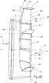
Des Weiteren ist es bevorzugt, dass die Strömungsleitfläche als Düse und besonders bevorzugterweise als Vordüse ausgebildet ist. Hierfür ist die Strömungsleitfläche derart geformt, dass sie nicht nur die Eigenschaft besitzt, die Strömung gezielt auf den Propeller zu leiten, sondern zusätzlich auch derart geformt ist, dass die Zuströmgeschwindigkeit zumindest bereichsweise erhöht wird. Dies kann beispielsweise bei einer bogenförmig ausgebildeten Strömungsleitfläche vorgesehen sein, bei der der Radius des Rings (bei Querschnittsbetrachtung) in Längsrichtung der Strömungsleitfläche von vorne nach hinten zum Propeller hin abnimmt.Furthermore, it is preferred that the flow guide surface is formed as a nozzle and particularly preferably as a pre-nozzle. For this purpose, the flow guide is shaped such that it not only has the property to direct the flow targeted to the propeller, but is also additionally shaped so that the inflow is increased at least in some areas. This may be provided, for example, in the case of an arc-shaped flow-guiding surface, in which the radius of the ring (in the case of a cross-sectional view) decreases in the longitudinal direction of the flow guide from front to back towards the propeller.
Unter Vordüse ist eine Düse zu verstehen, welche in Fahrtrichtung des Schiffes beziehungsweise Wasserfahrzeuges vor dem Propeller des Wasserfahrzeuges angeordnet ist.Under pre-nozzle is to be understood a nozzle which is arranged in the direction of travel of the vessel or watercraft in front of the propeller of the vessel.
Bei einer bevorzugten Ausführungsform, wobei die Strömungsleitfläche als Düse oder Vordüse ausgebildet ist, ist innerhalb der Düse beziehungsweise Vordüse kein Propeller, anders als zum Beispiel bei Kortdüsen oder Ruderpropellern angeordnet. Des Weiteren ist auch die Düse beziehungsweise Vordüse, wie auch die nicht als Düse ausgebildete Strömungsleitfläche, beabstandet zum Propeller angeordnet. Die Düse beziehungsweise Vordüse ist derart ausgebildet, dass die hindurchströmende Wasserströmung zumindest teilweise auf den nachstehend angeordneten Propeller geleitet wird. In der Regel wird die Düse beziehungsweise Vordüse eine röhrenförmige Form aufweisen. Es ist jedoch auch grundsätzlich jede anderweitige Querschnittsform, beispielsweise eine eckige Querschnittsform denkbar.In a preferred embodiment, wherein the flow guide is designed as a nozzle or pre-nozzle, within the nozzle or pre-nozzle no propeller, unlike for example in Kortdüsen or rudder propellers arranged. Furthermore, the nozzle or pre-nozzle, as well as the not designed as a nozzle flow guide, spaced from the propeller. The nozzle or pre-nozzle is designed such that the water flow flowing through it is at least partially directed onto the propeller arranged below. In general, the nozzle or pre-nozzle will have a tubular shape. However, it is also basically any other cross-sectional shape, such as a polygonal cross-sectional shape conceivable.
Die Düse beziehungsweise Vordüse kann einteilig beziehungsweise einstückig ausgebildet sein, oder aus mehreren Einzelteilen zu einer Düse beziehungsweise Vordüse zusammengesetzt sein, wobei die Einzelteile bevorzugt miteinander beziehungsweise mit der Schiffshülle verschweißt sind. Bevorzugt ist zumindest ein Teilbereich der Düse beziehungsweise Vordüse unterhalb der Propellerwelle des Schiffspropellers angeordnet.The nozzle or pre-nozzle may be formed integrally or in one piece, or composed of several individual parts to form a nozzle or pre-nozzle, wherein the individual parts are preferably welded to each other or to the ship hull. Preferably, at least a portion of the nozzle or pre-nozzle is arranged below the propeller shaft of the ship propeller.
Grundsätzlich ist es möglich, dass die Düse beziehungsweise Vordüse nur einen Teilausschnitt einer Düse beziehungsweise eines Düsenrings umfasst (zum Beispiel einen Viertel-Düsenring, einen Drittel-Düsenring, einen halben Düsenring, usw.). Bei einer solchen Ausführungsform ist die Düse beziehungsweise Vordüse über den Umfang gesehen offen ausgebildet.In principle, it is possible that the nozzle or pre-nozzle only a partial section of a nozzle or a nozzle ring comprises (for example, a quarter-nozzle ring, a third nozzle ring, a half nozzle ring, etc.). In such an embodiment, the nozzle or pre-nozzle seen over the circumference is open.
Bevorzugt ist die Düse beziehungsweise Vordüse jedoch in Umfangsrichtung geschlossen ausgebildet. Hierfür kann die Düse beziehungsweise Vordüse in Umfangsrichtung um 360 Grad durchgehend ausgebildet sein. Bei einer mehrteilig ausgebildeten Düse beziehungsweise Vordüse können ferner, insbesondere auch bei geschlossenem Düsenumfang, die Einzelteile der Düse beziehungsweise Vordüse mit der Schiffshülle und/oder dem Stevenrohr verbunden sein, sodass dann die Schiffshülle und/oder das Stevenrohr einen Teil des Düsenumfangs bildet.Preferably, however, the nozzle or pre-nozzle is designed to be closed in the circumferential direction. For this purpose, the nozzle or pre-nozzle can be designed to be continuous in the circumferential direction by 360 degrees. In the case of a multi-part nozzle or pre-nozzle, the individual parts of the nozzle or pre-nozzle can furthermore be connected to the hull and / or the stern tube, in particular even when the nozzle circumference is closed, so that the hull and / or the stern tube forms part of the nozzle circumference.
Bei sämtlichen vorgenannten Ausführungsformen der Vorrichtung kann die Strömungsleitfläche als Düse beziehungsweise Vordüse ausgebildet sein. Bei einer derartigen Ausgestaltung sind die ersten Fins von der Düse beziehungsweise Vordüse nach außen vorstehend angeordnet. Deshalb werden bei einer derartigen Ausführungsform die ersten Fins auch Außen-Fins genannt. Dagegen sind die zweiten Fins bei Vorsehen einer Strömungsleitfläche als Düse oder Vordüse innerhalb der Düse beziehungsweise Vordüse angeordnet. Diese zweiten Fins werden demnach auch Innen-Fins genannt.In all the aforementioned embodiments of the device, the flow guide may be formed as a nozzle or pre-nozzle. In such an embodiment, the first fins are projected outwardly from the nozzle or pre-nozzle. Therefore, in such an embodiment, the first fins are also called outside fins. In contrast, the second fins are arranged with provision of a flow guide as a nozzle or pre-nozzle within the nozzle or pre-nozzle. These second fins are therefore also called inside fins.
Durch das bevorzugte im Umfang geschlossene Profil der Düse beziehungsweise Vordüse weist diese einen inneren Bereich auf, welcher durch den Düsenmantel einer an den beiden Öffnungen (Wassereintritts- und Wasseraustrittsöffnung) gedanklich geschlossenen Düse beziehungsweise Vordüse eingeschlossen ist. Der mindestens eine Außen-Fin ist nunmehr bevorzugterweise außerhalb dieses inneren Bereichs angeordnet und steht vielmehr von der Vordüse beziehungsweise Düse aus gesehen, nach außen hin vor. Insbesondere kann der mindestens eine Außen-Fin von der Außenseite der Düse beziehungsweise Vordüse vorstehen.Due to the preferred circumferentially closed profile of the nozzle or pre-nozzle, this has an inner region, which is enclosed by the nozzle shell of a nozzle or pre-nozzle intentionally closed at the two openings (water inlet and water outlet openings). The at least one outer fin is now preferably arranged outside this inner region and, rather, as seen from the pre-nozzle or nozzle, projects outwards. In particular, the at least one outer fin may protrude from the outside of the nozzle or pre-nozzle.
Im Gegensatz zum Stand der Technik wird nunmehr auch außerhalb der Düse beziehungsweise Vordüse ein zur Düse beziehungsweise Vordüse gehörender Fin, der mindestens eine Außen-Fin, vorgesehen. Zweckmäßigerweise ist wenigstens ein Endbereich des Außen-Fins an der äußeren Wandfläche der Düse beziehungsweise Vordüse angeordnet und steht von dieser nach außen hin vor. Das heißt, der restliche Bereich des mindestens einen Außen-Fins ist beabstandet von der Düse beziehungsweise Vordüse angeordnet. Durch die erstmalige Anordnung eines Fins außen an einer Düse beziehungsweise Vordüse wird nunmehr erreicht, dass der Durchmesser und/oder die Profildicke der Düse beziehungsweise Vordüse gegenüber den aus dem Stand der Technik bekannten Vorrichtungen deutlich reduziert werden kann und der mindestens eine Außen-Fin trotzdem noch diejenigen Bereiche erreicht, in denen die Strömungsverluste besonders hoch sind und in denen ein Vordrall für einen effizienten Betrieb erzeugt werden muss. Würde man die Durchmesser bei den aus dem Stand der Technik bekannten Vorrichtungen einfach nur verringern, würden die Fins im Gegensatz zur vorliegenden Erfindung nicht weit genug von der Propellernabe wegreichen (in Radialrichtung von der Propellernabe ausgesehen) und somit die Zuströmung auf den jeweils zugeordneten Propeller nicht mehr oder nur in geringem Maße positiv beeinflussen.In contrast to the prior art now also outside the nozzle or pre-nozzle belonging to the nozzle or pre-nozzle Fin, the at least one outer fin, provided. Conveniently, at least one end region of the outer fin is arranged on the outer wall surface of the nozzle or pre-nozzle and protrudes outward from the latter. That is, the remaining portion of the at least one outer fin is spaced from the nozzle or pre-nozzle. By the first-time arrangement of a fin on the outside of a nozzle or pre-nozzle it is now achieved that the diameter and / or the profile thickness of the nozzle or pre-nozzle compared to the devices known from the prior art can be significantly reduced and the at least one outdoor fin still still reaches those areas in which the flow losses are particularly high and in which a Vordrall must be generated for efficient operation. If the diameters were simply reduced in the devices known from the prior art, the fins, in contrast to the present invention, would not extend far enough away from the propeller hub (viewed radially from the propeller hub) and thus the inflow to the respectively assigned propeller would not influence more or less positively.
Durch die Anbringung eines oder mehrerer Außen-Fins an der Außenseite der Vordüse beziehungsweise Düse kann der Durchmesser der Düse beziehungsweise Vordüse und damit deren Widerstand verringert werden, sodass die Vorrichtung nunmehr auch für schnelle und sehr schnelle Schiffe anwendbar ist, wobei die positiven Wirkungen auf die Verringerung des Antriebsleistungsbedarfs erhalten bleiben beziehungsweise gegebenenfalls sogar noch verbessert werden. Dadurch, dass der Außen-Fin von der Düse beziehungsweise Vordüse nach außen vorsteht und nicht etwa von der Propellernabe beziehungsweise dem Stevenrohr, kann dieser relativ weit nach außen von der Propellerachse aus gesehen reichen und trotzdem noch eine ausreichende Festigkeit, insbesondere in Bezug auf Biegebeanspruchungen, aufweisen.By attaching one or more external fins on the outside of the pre-nozzle or nozzle, the diameter of the nozzle or pre-nozzle and thus their resistance can be reduced, so that the device is now also applicable to fast and very fast ships, the positive effects on the Reduction of the drive power requirement to be maintained or possibly even improved. Due to the fact that the outer fin protrudes outwards from the nozzle or pre-nozzle and not from the propeller hub or sterntube, the latter can extend relatively far outward from the propeller axis and still have sufficient strength, in particular with regard to bending stresses. exhibit.
Die Düse beziehungsweise Vordüse kann rotationssymmetrisch oder auch rotationsasymmetrisch ausgebildet sein. Ferner kann die Düse beziehungsweise Vordüse konzentrisch mit der Propellerachse oder auch exzentrisch hierzu angeordnet sein. Insbesondere kann die Rotationsachse und/oder die Längsachse der Düse beziehungsweise Vordüse gegenüber der Propellerachse nach oben und/oder seitlich versetzt angeordnet sein. Ferner kann die Düse beziehungsweise Vordüse derart angeordnet sein, dass ihre Rotationsachse oder ihre Längsachse parallel zur Propellerachse verläuft oder in einem Winkel zur Propellerachse verläuft und somit in Bezug auf die Propellerachse schräg gestellt ist. Bevorzugt ist die Düse beziehungsweise Vordüse ferner in horizontaler Richtung mittig, bezogen auf die Propellerachse, ausgerichtet. Dadurch liegen die Rotationsachse der Düse beziehungsweise Vordüse und die Propellerachse in einer vertikalen Ebene. Grundsätzlich ist jedoch eine verdrehte Anordnung der Düse beziehungsweise Vordüse gegenüber einer durch die Propellerachse verlaufenden Vertikalen beziehungsweise einer Parallelen hierzu möglich.The nozzle or pre-nozzle may be rotationally symmetrical or rotationally asymmetrical. Furthermore, the nozzle or pre-nozzle can be arranged concentrically with the propeller axis or eccentrically thereto. In particular, the axis of rotation and / or the longitudinal axis of the nozzle or pre-nozzle relative to the propeller axis can be arranged offset upwards and / or laterally. Furthermore, the nozzle or pre-nozzle can be arranged such that its axis of rotation or its longitudinal axis is parallel to the propeller axis or extends at an angle to the propeller axis and is thus inclined with respect to the propeller axis. Preferably, the nozzle or pre-nozzle is further centered in the horizontal direction, with respect to the propeller axis aligned. As a result, the axis of rotation of the nozzle or pre-nozzle and the propeller axis lie in a vertical plane. In principle, however, a twisted arrangement of the nozzle or pre-nozzle relative to a vertical axis extending through the propeller axis or a parallel thereto is possible.
Die Verschiebung der Düse beziehungsweise Vordüse gegenüber der Propellerachse nach oben und/oder zur Seite, kann insbesondere deswegen vorteilhaft sein, da die Wassergeschwindigkeit aufgrund der Schiffform beziehungsweise der Ausgestaltung des Schiffskörpers im unteren Bereich der Vordüse beziehungsweise des Propellers in der Regel schneller ist als im oberen Bereich. Durch die Verschiebung der Vordüse gegenüber der Propellerachse kann, angepasst an die jeweilige Gestaltung des Schiffskörpers, gegebenenfalls eine Vergleichsmäßigung des Propellerzustroms und somit ein besserer Wirkungsgrad erreicht werden.The displacement of the nozzle or pre-nozzle relative to the propeller axis upwards and / or to the side may be particularly advantageous because the water velocity is usually faster due to the shape of the ship or the design of the hull in the lower region of the pre-nozzle or the propeller as in the upper Area. Due to the displacement of the pre-nozzle relative to the propeller axis, it is possible, if necessary, to achieve an equalization of the propeller inflow and thus a better efficiency, adapted to the respective design of the hull.
Zweckmäßigerweise besteht die Vordüse aus einem durchgehenden und/oder einstückigen Ringkörper beziehungsweise Düsenring. Die bevorzugte Ausführungsform kann auch bei Mehrschraubenschiffen eingesetzt werden, wobei dann zweckmäßigerweise jedem Propeller eine Düse beziehungsweise Vordüse zuzuordnen ist. Die der Vorrichtung zugeordneten Propeller sind in der Regel feststehend beziehungsweise lagefixiert am Schiffskörper installiert. Die Vordüse beziehungsweise Düse bildet zusammen mit dem Propeller des Wasserfahrzeuges ein Antriebssystem.Conveniently, the pre-nozzle consists of a continuous and / or one-piece annular body or nozzle ring. The preferred embodiment can also be used in multi-screw ships, in which case expediently each propeller is assigned a nozzle or pre-nozzle. The propeller associated with the device are usually fixed or fixed in position on the hull installed. The pre-nozzle or nozzle together with the propeller of the watercraft forms a drive system.
Des Weiteren ist es vorteilhaft, wenn der Durchmesser der Düse beziehungsweise Vordüse nicht mehr als 85%, bevorzugt nicht mehr als 70%, besonders bevorzugt nicht mehr als 50% oder nicht mehr als 35% desjenigen Durchmessers des Propellers beträgt, dem die Düse beziehungsweise Vordüse zugeordnet ist. Auch hierdurch wird sichergestellt, dass das Düsenprofil beziehungsweise der Düsenring insgesamt nicht zu groß wird, damit der Widerstand der Düse beziehungsweise Vordüse so niedrig ist, dass es möglich ist, die Vorrichtung auch bei schnellen und sehr schnellen Schiffen einzusetzen. Sollte die Düse beziehungsweise Vordüse nicht rotationssymmetrisch beziehungsweise zylindrisch oder kegelförmig ausgebildet sein, kann statt dem Durchmesser die größte Ausdehnung der Düse beziehungsweise Vordüse in Höhe oder Breite ins Verhältnis zum Propellerdurchmesser gesetzt werden. Ferner ist zweckmäßigerweise den Außendurchmesser der Vordüse anzusetzen.Furthermore, it is advantageous if the diameter of the nozzle or pre-nozzle is not more than 85%, preferably not more than 70%, particularly preferably not more than 50% or not more than 35% of that diameter of the propeller to which the nozzle or pre-nozzle assigned. This also ensures that the nozzle profile or the nozzle ring as a whole is not too large, so that the resistance of the nozzle or pre-nozzle is so low that it is possible to use the device even in fast and very fast ships. If the nozzle or pre-nozzle is not rotationally symmetrical or cylindrical or cone-shaped, instead of the diameter, the greatest extent of the nozzle or pre-nozzle in height or width can be set in relation to the propeller diameter. Furthermore, it is expedient to set the outer diameter of the pre-nozzle.
Die Erfindung wird nachfolgend anhand der in der Zeichnung dargestellten Ausführungsbeispiele weiter erläutert. Es zeigen schematisch:The invention will be further explained with reference to the embodiments illustrated in the drawings. They show schematically:
Bei den im Folgenden dargestellten, verschiedenen Ausführungsformen sind gleiche Bestandteile mit gleichen Bezugszeichen versehen.In the various embodiments shown below, the same components are provided with the same reference numerals.
Die Strömungsleitfläche
Die in
Die Vordüse
Auf der propelleraufschlagenden Seite
Insgesamt sind auf der propelleraufschlagenden Seite
Die Außen-Fins
Die Fin-Endstücke
Die Außen-Fins
Im Gegensatz dazu sind die Außen-Fins
In der
Im Gegensatz zur Ausführungsform nach den
Ferner ist in
BezugszeichenlisteLIST OF REFERENCE NUMBERS
- 100100
- Vorrichtungcontraption
- 1010
- Vordüseprenozzle
- 1111
- VordüsenwandVordüsenwand
- 1212
- innere Vordüsenwandflächeinner pre-nozzle wall surface
- 1313
- äußere Vordüsenwandflächeouter pre-nozzle wall surface
- 1414
- Propelleraufschlagende SeitePropelleraufschlagende side
- 1515
- Propellerabschlagende SeitePropeller rebounding side
- 1616
- Rotationsachse der VordüseRotation axis of the pre-nozzle
- 1717
- Orthogonale zur RotationsachseOrthogonal to the axis of rotation
- 18 18
- HauptanströmungsrichtungHauptanströmungsrichtung
- 20, 20a, 20b, 20c, 20d20, 20a, 20b, 20c, 20d
- Außen-FinsOutdoor Fins
- 201201
- erstes Ende Außen-Finfirst end outer fin
- 202202
- zweites Ende Außen-Finsecond end outside fin
- 203203
- Saugseitesuction
- 204204
- Druckseitepressure side
- 205205
- vordere Stirnseitefront end
- 206206
- rückwärtige Stirnseiterearward face
- 21a, 21b, 21c, 21d21a, 21b, 21c, 21d
- Innen-FinsInside Fins
- 2222
- Stabilisierungsstrebestabilizing strut
- 2323
- Fin-EndstückeFin Tails
- 23a23a
- Übergangcrossing
- 3030
- Schiffskörperhull
- 3131
- Wellenlagershaft bearing
- 3232
- Propellerachsepropeller axis
- 3333
- Propellerpropeller
- 3434
- Vertikale MittenlinieVertical centerline
- 3535
- Horizontale MittenlinieHorizontal centerline
- 3636
- Ruderrudder
- 3737
- Fahrtrichtungdirection of travel
- 5050
- Strömungsleitflächeflow guide
- 50a50a
- erster Finfirst fin
- 5151
- Profildicke der StrömungsleitflächeProfile thickness of the flow guide surface
- 51a51a
- zweiter Finsecond fin
- 5252
- ProfileintrittskanteProfile leading edge
- 5353
- ProfilaustrittskanteProfile trailing edge
- 5454
- Abstand zwischen Strömungsleitfläche und PropellerachseDistance between the flow guide surface and the propeller axis
- 5555
- PropellerdurchmesserPropeller diameter
- 501501
- erstes Ende des ersten Finsfirst end of the first fins
- 502502
- zweites Ende des ersten Finssecond end of the first fin
- 503503
- erstes Ende des zweiten Finsfirst end of the second fin
- 504504
- zweites Ende des zweiten Finssecond end of the second fin
- αα
- Schnittwinkel zwischen Rotationsachse und PropellerachseCutting angle between rotation axis and propeller axis
- ββ
- Pfeilungswinkelsweep angle
ZITATE ENTHALTEN IN DER BESCHREIBUNG QUOTES INCLUDE IN THE DESCRIPTION
Diese Liste der vom Anmelder aufgeführten Dokumente wurde automatisiert erzeugt und ist ausschließlich zur besseren Information des Lesers aufgenommen. Die Liste ist nicht Bestandteil der deutschen Patent- bzw. Gebrauchsmusteranmeldung. Das DPMA übernimmt keinerlei Haftung für etwaige Fehler oder Auslassungen.This list of the documents listed by the applicant has been generated automatically and is included solely for the better information of the reader. The list is not part of the German patent or utility model application. The DPMA assumes no liability for any errors or omissions.
Zitierte PatentliteraturCited patent literature
- EP 2100808 A1 [0002] EP 2100808 A1 [0002]
Claims (26)
Priority Applications (19)
| Application Number | Priority Date | Filing Date | Title |
|---|---|---|---|
| DE202013101943U DE202013101943U1 (en) | 2013-05-06 | 2013-05-06 | Device for reducing the power requirement of a watercraft |
| CN201320835028.8U CN203958582U (en) | 2013-05-06 | 2013-12-14 | For reducing the device of boats and ships driving power demand |
| SG11201509192TA SG11201509192TA (en) | 2013-05-06 | 2014-03-31 | Device for reducing the driving power requirement of a watercraft |
| CA2911459A CA2911459C (en) | 2013-05-06 | 2014-03-31 | Device for reducing the drive power requirement of a watercraft |
| US14/889,491 US10005530B2 (en) | 2013-05-06 | 2014-03-31 | Device for improving the water influx towards a propeller of a watercraft |
| JP2016512256A JP6678575B2 (en) | 2013-05-06 | 2014-03-31 | Equipment for reducing the required driving force of ships |
| PCT/EP2014/056412 WO2014180605A1 (en) | 2013-05-06 | 2014-03-31 | Device for reducing the driving power requirement of a watercraft |
| KR1020157034659A KR20160031452A (en) | 2013-05-06 | 2014-03-31 | Device for reducing the driving power requirement of a watercraft |
| KR1020227020830A KR102512176B1 (en) | 2013-05-06 | 2014-03-31 | Device for reducing the driving power requirement of a watercraft |
| DK14717112.8T DK2994379T3 (en) | 2013-05-06 | 2014-03-31 | ESTABLISHMENT TO REDUCE A VESSEL'S NEED FOR POWER PLANT |
| EP14717112.8A EP2994379B1 (en) | 2013-05-06 | 2014-03-31 | Apparatus to reduce required propulsion power of waterborne vessel |
| ES14717112T ES2737453T3 (en) | 2013-05-06 | 2014-03-31 | Device for reducing the need for propulsion power of a boat |
| TR2019/08084T TR201908084T4 (en) | 2013-05-06 | 2014-03-31 | Device for reducing the drive power requirement of a watercraft. |
| PL14717112T PL2994379T3 (en) | 2013-05-06 | 2014-03-31 | Apparatus to reduce required propulsion power of waterborne vessel |
| CN201480036775.2A CN105452100B (en) | 2013-05-06 | 2014-03-31 | Device for reducing the drive power requirement of a watercraft |
| KR1020217002742A KR102412435B1 (en) | 2013-05-06 | 2014-03-31 | Device for reducing the driving power requirement of a watercraft |
| TW103115913A TWI637881B (en) | 2013-05-06 | 2014-05-05 | Device for reducing ship driving power requirements |
| HK16107077.3A HK1219080A1 (en) | 2013-05-06 | 2016-06-20 | Device for reducing the driving power requirement of a watercraft |
| HRP20190973TT HRP20190973T1 (en) | 2013-05-06 | 2019-05-28 | Apparatus to reduce required propulsion power of waterborne vessel |
Applications Claiming Priority (1)
| Application Number | Priority Date | Filing Date | Title |
|---|---|---|---|
| DE202013101943U DE202013101943U1 (en) | 2013-05-06 | 2013-05-06 | Device for reducing the power requirement of a watercraft |
Publications (1)
| Publication Number | Publication Date |
|---|---|
| DE202013101943U1 true DE202013101943U1 (en) | 2013-06-11 |
Family
ID=48784199
Family Applications (1)
| Application Number | Title | Priority Date | Filing Date |
|---|---|---|---|
| DE202013101943U Expired - Lifetime DE202013101943U1 (en) | 2013-05-06 | 2013-05-06 | Device for reducing the power requirement of a watercraft |
Country Status (16)
| Country | Link |
|---|---|
| US (1) | US10005530B2 (en) |
| EP (1) | EP2994379B1 (en) |
| JP (1) | JP6678575B2 (en) |
| KR (3) | KR20160031452A (en) |
| CN (2) | CN203958582U (en) |
| CA (1) | CA2911459C (en) |
| DE (1) | DE202013101943U1 (en) |
| DK (1) | DK2994379T3 (en) |
| ES (1) | ES2737453T3 (en) |
| HK (1) | HK1219080A1 (en) |
| HR (1) | HRP20190973T1 (en) |
| PL (1) | PL2994379T3 (en) |
| SG (1) | SG11201509192TA (en) |
| TR (1) | TR201908084T4 (en) |
| TW (1) | TWI637881B (en) |
| WO (1) | WO2014180605A1 (en) |
Cited By (2)
| Publication number | Priority date | Publication date | Assignee | Title |
|---|---|---|---|---|
| EP3064427A1 (en) * | 2015-03-06 | 2016-09-07 | becker marine systems GmbH & Co. KG | Assembly for multi-screws ships having external propeller shafts and a method of manufacturing such an assembly |
| WO2021239963A1 (en) * | 2020-05-28 | 2021-12-02 | Becker Marine Systems Gmbh | Arrangement for reducing a drive power requirement of a watercraft |
Families Citing this family (7)
| Publication number | Priority date | Publication date | Assignee | Title |
|---|---|---|---|---|
| DE202013101943U1 (en) * | 2013-05-06 | 2013-06-11 | Becker Marine Systems Gmbh & Co. Kg | Device for reducing the power requirement of a watercraft |
| CN104828226A (en) * | 2015-04-21 | 2015-08-12 | 中国船舶工业集团公司第七〇八研究所 | Auxiliary propulsion energy-saving device for ship hydrodynamics |
| JP6239711B1 (en) * | 2016-09-15 | 2017-11-29 | サノヤス造船株式会社 | Ship duct equipment |
| SE544385C2 (en) * | 2019-09-23 | 2022-05-03 | Volvo Penta Corp | Propeller combination for a marine vessel |
| CN114379752B (en) * | 2021-12-09 | 2022-08-26 | 南通海国机械有限公司 | Leading guide pulley of prewhirling for boats and ships |
| FI20225121A1 (en) * | 2022-02-11 | 2023-08-12 | Kongsberg Maritime Finland Oy | A flow guide arrangement of a rectracable thruster, a rectracable thruster, and a system |
| WO2024025376A1 (en) * | 2022-07-27 | 2024-02-01 | 에이치디한국조선해양 주식회사 | Ship structure |
Citations (1)
| Publication number | Priority date | Publication date | Assignee | Title |
|---|---|---|---|---|
| EP2100808A1 (en) | 2008-03-10 | 2009-09-16 | Becker Marine Systems GmbH & Co. KG | Device for lowering the drive output requirements of a ship |
Family Cites Families (22)
| Publication number | Priority date | Publication date | Assignee | Title |
|---|---|---|---|---|
| JPS5332594A (en) * | 1976-09-07 | 1978-03-27 | Hitachi Zosen Corp | Ship |
| JPS595680Y2 (en) * | 1980-07-22 | 1984-02-20 | 三菱重工業株式会社 | Ship propulsion performance improvement device |
| JPS60139699U (en) * | 1984-02-29 | 1985-09-14 | 三菱重工業株式会社 | Marine nozzle device |
| US5292088A (en) * | 1989-10-10 | 1994-03-08 | Lemont Harold E | Propulsive thrust ring system |
| US5634613A (en) * | 1994-07-18 | 1997-06-03 | Mccarthy; Peter T. | Tip vortex generation technology for creating a lift enhancing and drag reducing upwash effect |
| US5906522A (en) * | 1998-04-01 | 1999-05-25 | Hooper; Robert P. | Thrust enhancer for marine propeller |
| KR100394464B1 (en) | 2000-12-01 | 2003-08-09 | 현대중공업 주식회사 | Y-shaped stator |
| US7267589B2 (en) * | 2004-07-22 | 2007-09-11 | Enviroprop Corporation | System and apparatus for improving safety and thrust from a hydro-drive device |
| KR100625847B1 (en) * | 2004-10-14 | 2006-09-20 | 부산대학교 산학협력단 | Asymmetric Pre-swirl Stator for Cavitation Suppression |
| KR100640299B1 (en) * | 2005-04-14 | 2006-10-30 | 대우조선해양 주식회사 | Installation structure for preswirl stator of ship |
| JP4717857B2 (en) * | 2007-06-14 | 2011-07-06 | 住友重機械マリンエンジニアリング株式会社 | Ship duct and ship |
| TW201010908A (en) * | 2008-09-02 | 2010-03-16 | Jen-Chen Tuan | Easily operable aircraft |
| JP2010195153A (en) * | 2009-02-24 | 2010-09-09 | Mitsubishi Heavy Ind Ltd | Reaction fin device for ship and ship |
| KR101023052B1 (en) | 2009-09-17 | 2011-03-24 | 대우조선해양 주식회사 | Ducted pre-swirl stator |
| KR20120068250A (en) | 2010-12-17 | 2012-06-27 | 현대중공업 주식회사 | Duct structure for ship |
| DE202011000439U1 (en) * | 2011-02-25 | 2012-08-21 | Becker Marine Systems Gmbh & Co. Kg | Pre-nozzle for a propulsion system of a watercraft to improve energy efficiency |
| KR101334217B1 (en) * | 2011-05-03 | 2013-11-29 | 에스피피조선 주식회사 | Fuel-efficiecy Improving crown duct for ship |
| KR101723240B1 (en) * | 2011-05-13 | 2017-04-18 | 현대중공업 주식회사 | Propeller Duct Structure of Ship with Multi-Column Fin |
| CN202244050U (en) | 2011-08-17 | 2012-05-30 | 上海船舶研究设计院 | Reaction fin in front of oar |
| DE102011053619A1 (en) * | 2011-09-14 | 2013-03-14 | Becker Marine Systems Gmbh & Co. Kg | Propeller nozzle for watercraft |
| PT2591994E (en) * | 2011-11-11 | 2014-09-18 | Becker Marine Sys Gmbh & Co Kg | Device for lowering the fuel consumption of the propulsion of a watercraft |
| DE202013101943U1 (en) * | 2013-05-06 | 2013-06-11 | Becker Marine Systems Gmbh & Co. Kg | Device for reducing the power requirement of a watercraft |
-
2013
- 2013-05-06 DE DE202013101943U patent/DE202013101943U1/en not_active Expired - Lifetime
- 2013-12-14 CN CN201320835028.8U patent/CN203958582U/en not_active Expired - Lifetime
-
2014
- 2014-03-31 ES ES14717112T patent/ES2737453T3/en active Active
- 2014-03-31 PL PL14717112T patent/PL2994379T3/en unknown
- 2014-03-31 DK DK14717112.8T patent/DK2994379T3/en active
- 2014-03-31 KR KR1020157034659A patent/KR20160031452A/en not_active Application Discontinuation
- 2014-03-31 KR KR1020217002742A patent/KR102412435B1/en active IP Right Grant
- 2014-03-31 CA CA2911459A patent/CA2911459C/en active Active
- 2014-03-31 WO PCT/EP2014/056412 patent/WO2014180605A1/en active Application Filing
- 2014-03-31 JP JP2016512256A patent/JP6678575B2/en active Active
- 2014-03-31 SG SG11201509192TA patent/SG11201509192TA/en unknown
- 2014-03-31 CN CN201480036775.2A patent/CN105452100B/en active Active
- 2014-03-31 EP EP14717112.8A patent/EP2994379B1/en active Active
- 2014-03-31 US US14/889,491 patent/US10005530B2/en active Active
- 2014-03-31 TR TR2019/08084T patent/TR201908084T4/en unknown
- 2014-03-31 KR KR1020227020830A patent/KR102512176B1/en active IP Right Grant
- 2014-05-05 TW TW103115913A patent/TWI637881B/en active
-
2016
- 2016-06-20 HK HK16107077.3A patent/HK1219080A1/en unknown
-
2019
- 2019-05-28 HR HRP20190973TT patent/HRP20190973T1/en unknown
Patent Citations (1)
| Publication number | Priority date | Publication date | Assignee | Title |
|---|---|---|---|---|
| EP2100808A1 (en) | 2008-03-10 | 2009-09-16 | Becker Marine Systems GmbH & Co. KG | Device for lowering the drive output requirements of a ship |
Cited By (5)
| Publication number | Priority date | Publication date | Assignee | Title |
|---|---|---|---|---|
| EP3064427A1 (en) * | 2015-03-06 | 2016-09-07 | becker marine systems GmbH & Co. KG | Assembly for multi-screws ships having external propeller shafts and a method of manufacturing such an assembly |
| CN105936332A (en) * | 2015-03-06 | 2016-09-14 | 贝克船舶系统有限及两合公司 | Arrangement for multi screw vessels comprising external propeller shafts as well as method for producing such an arrangement |
| US9789943B2 (en) | 2015-03-06 | 2017-10-17 | Becker Marine Systems Gmbh & Co. Kg | Arrangement for multi screw vessels comprising external propeller shafts as well as method for producing such an arrangement |
| CN105936332B (en) * | 2015-03-06 | 2021-04-27 | 贝克船舶系统有限公司 | Arrangement for a multi-propeller vessel comprising an outer propeller shaft and method for producing such an arrangement |
| WO2021239963A1 (en) * | 2020-05-28 | 2021-12-02 | Becker Marine Systems Gmbh | Arrangement for reducing a drive power requirement of a watercraft |
Also Published As
| Publication number | Publication date |
|---|---|
| DK2994379T3 (en) | 2019-06-03 |
| WO2014180605A1 (en) | 2014-11-13 |
| PL2994379T3 (en) | 2019-09-30 |
| JP6678575B2 (en) | 2020-04-08 |
| TR201908084T4 (en) | 2019-06-21 |
| EP2994379B1 (en) | 2019-05-01 |
| CN105452100A (en) | 2016-03-30 |
| CA2911459C (en) | 2019-10-15 |
| EP2994379A1 (en) | 2016-03-16 |
| JP2016520474A (en) | 2016-07-14 |
| HRP20190973T1 (en) | 2019-07-26 |
| TW201502008A (en) | 2015-01-16 |
| CA2911459A1 (en) | 2014-11-13 |
| KR102412435B1 (en) | 2022-06-23 |
| US20160090163A1 (en) | 2016-03-31 |
| US10005530B2 (en) | 2018-06-26 |
| ES2737453T3 (en) | 2020-01-14 |
| CN203958582U (en) | 2014-11-26 |
| KR102512176B1 (en) | 2023-03-21 |
| KR20220092633A (en) | 2022-07-01 |
| KR20160031452A (en) | 2016-03-22 |
| TWI637881B (en) | 2018-10-11 |
| CN105452100B (en) | 2022-01-28 |
| SG11201509192TA (en) | 2015-12-30 |
| HK1219080A1 (en) | 2017-03-24 |
| KR20210024140A (en) | 2021-03-04 |
Similar Documents
| Publication | Publication Date | Title |
|---|---|---|
| EP2591994B1 (en) | Device for lowering the fuel consumption of the propulsion of a watercraft | |
| EP2994379B1 (en) | Apparatus to reduce required propulsion power of waterborne vessel | |
| EP3064427B1 (en) | Assembly for multi-screws ships having external propeller shafts and a method of manufacturing such an assembly | |
| EP2100809B1 (en) | Device for lowering the drive output requirements of a ship | |
| EP2597030B1 (en) | Pre-nozzle for a propulsion system of a water vehicle for improving energy efficiency | |
| EP2060484B2 (en) | Rudder for ships | |
| EP2060485B1 (en) | Rudder assembly for ships with high speeds with a cavitation reducing, twisted, in particular floating rudder | |
| EP2154064B1 (en) | Rudder assembly for ships with high speeds with a cavitation reducing, twisted, in particular floating rudder | |
| EP2060482B1 (en) | Kort nozzle | |
| DE1934246A1 (en) | Boundary layer control for flow separation and heat exchange | |
| EP2277772B1 (en) | Ducted propeller for ships | |
| DE102011055515A1 (en) | Propeller arrangement, in particular for watercraft | |
| EP2594784A2 (en) | Vertical wind turbine and rotor blade for the same | |
| DE2439683C2 (en) | ||
| DE2636261C2 (en) | Annular structure on the stern of the ship | |
| DE112012007098T5 (en) | Ship propulsion device and ship provided with such a device | |
| DE202009002642U1 (en) | Device for reducing the power requirement of a ship | |
| DE102010022070A1 (en) | Drive unit for watercraft, has driving element comprising drive blades that include convex outer surface edge and concave inner surface edge in cross-section, where drive blades are helically arranged at radial distance around shaft | |
| DE3410940A1 (en) | Rudder with blades and method of manufacturing it | |
| WO2022180008A1 (en) | Energy-saving arrangement for twin-screw ships | |
| DE819209C (en) | Propeller for propulsion of ships with an inner ring penetrating the propeller blades | |
| DE102022001071A1 (en) | Wing element | |
| AT118671B (en) | Propeller. | |
| DE102008035058A1 (en) | Rotor blade for wind-energy plant, has main blade and auxiliary blade that is radially diverging from main blade with respect to wind-induced rotation, where blade cross-section is tapered from hub in radial direction | |
| DD245850A1 (en) | COMPRESSOR FOR PROPELLERS OF SCREWS WITH RING-FORMED SURFACE |
Legal Events
| Date | Code | Title | Description |
|---|---|---|---|
| R207 | Utility model specification |
Effective date: 20130801 |
|
| R150 | Utility model maintained after payment of first maintenance fee after three years | ||
| R081 | Change of applicant/patentee |
Owner name: BECKER MARINE SYSTEMS GMBH, DE Free format text: FORMER OWNER: BECKER MARINE SYSTEMS GMBH & CO. KG, 21079 HAMBURG, DE |
|
| R082 | Change of representative |
Representative=s name: RGTH RICHTER GERBAULET THIELEMANN HOFMANN PATE, DE |
|
| R151 | Utility model maintained after payment of second maintenance fee after six years | ||
| R152 | Utility model maintained after payment of third maintenance fee after eight years | ||
| R071 | Expiry of right |