JP6678575B2 - Equipment for reducing the required driving force of ships - Google Patents
Equipment for reducing the required driving force of ships Download PDFInfo
- Publication number
- JP6678575B2 JP6678575B2 JP2016512256A JP2016512256A JP6678575B2 JP 6678575 B2 JP6678575 B2 JP 6678575B2 JP 2016512256 A JP2016512256 A JP 2016512256A JP 2016512256 A JP2016512256 A JP 2016512256A JP 6678575 B2 JP6678575 B2 JP 6678575B2
- Authority
- JP
- Japan
- Prior art keywords
- fin
- propeller
- guide surface
- fins
- flow guide
- Prior art date
- Legal status (The legal status is an assumption and is not a legal conclusion. Google has not performed a legal analysis and makes no representation as to the accuracy of the status listed.)
- Active
Links
- 230000000087 stabilizing effect Effects 0.000 claims description 12
- 238000011144 upstream manufacturing Methods 0.000 claims description 12
- 238000000034 method Methods 0.000 claims 1
- XLYOFNOQVPJJNP-UHFFFAOYSA-N water Substances O XLYOFNOQVPJJNP-UHFFFAOYSA-N 0.000 description 11
- 230000007423 decrease Effects 0.000 description 4
- 230000000694 effects Effects 0.000 description 4
- 238000005452 bending Methods 0.000 description 3
- 230000001976 improved effect Effects 0.000 description 3
- 238000006073 displacement reaction Methods 0.000 description 2
- 230000007704 transition Effects 0.000 description 2
- 241001417523 Plesiopidae Species 0.000 description 1
- 230000015572 biosynthetic process Effects 0.000 description 1
- 230000006835 compression Effects 0.000 description 1
- 238000007906 compression Methods 0.000 description 1
- 230000002349 favourable effect Effects 0.000 description 1
- 238000012423 maintenance Methods 0.000 description 1
- 230000004048 modification Effects 0.000 description 1
- 238000012986 modification Methods 0.000 description 1
- 230000005855 radiation Effects 0.000 description 1
- 238000000926 separation method Methods 0.000 description 1
- 230000006641 stabilisation Effects 0.000 description 1
- 238000011105 stabilization Methods 0.000 description 1
Images


Classifications
-
- B—PERFORMING OPERATIONS; TRANSPORTING
- B63—SHIPS OR OTHER WATERBORNE VESSELS; RELATED EQUIPMENT
- B63H—MARINE PROPULSION OR STEERING
- B63H1/00—Propulsive elements directly acting on water
- B63H1/02—Propulsive elements directly acting on water of rotary type
- B63H1/12—Propulsive elements directly acting on water of rotary type with rotation axis substantially in propulsive direction
- B63H1/14—Propellers
- B63H1/28—Other means for improving propeller efficiency
-
- B—PERFORMING OPERATIONS; TRANSPORTING
- B63—SHIPS OR OTHER WATERBORNE VESSELS; RELATED EQUIPMENT
- B63H—MARINE PROPULSION OR STEERING
- B63H5/00—Arrangements on vessels of propulsion elements directly acting on water
- B63H5/07—Arrangements on vessels of propulsion elements directly acting on water of propellers
- B63H5/16—Arrangements on vessels of propulsion elements directly acting on water of propellers characterised by being mounted in recesses; with stationary water-guiding elements; Means to prevent fouling of the propeller, e.g. guards, cages or screens
-
- F—MECHANICAL ENGINEERING; LIGHTING; HEATING; WEAPONS; BLASTING
- F04—POSITIVE - DISPLACEMENT MACHINES FOR LIQUIDS; PUMPS FOR LIQUIDS OR ELASTIC FLUIDS
- F04D—NON-POSITIVE-DISPLACEMENT PUMPS
- F04D29/00—Details, component parts, or accessories
- F04D29/40—Casings; Connections of working fluid
-
- Y—GENERAL TAGGING OF NEW TECHNOLOGICAL DEVELOPMENTS; GENERAL TAGGING OF CROSS-SECTIONAL TECHNOLOGIES SPANNING OVER SEVERAL SECTIONS OF THE IPC; TECHNICAL SUBJECTS COVERED BY FORMER USPC CROSS-REFERENCE ART COLLECTIONS [XRACs] AND DIGESTS
- Y02—TECHNOLOGIES OR APPLICATIONS FOR MITIGATION OR ADAPTATION AGAINST CLIMATE CHANGE
- Y02T—CLIMATE CHANGE MITIGATION TECHNOLOGIES RELATED TO TRANSPORTATION
- Y02T70/00—Maritime or waterways transport
- Y02T70/50—Measures to reduce greenhouse gas emissions related to the propulsion system
Landscapes
- Engineering & Computer Science (AREA)
- Mechanical Engineering (AREA)
- Chemical & Material Sciences (AREA)
- Combustion & Propulsion (AREA)
- Ocean & Marine Engineering (AREA)
- General Engineering & Computer Science (AREA)
- Structures Of Non-Positive Displacement Pumps (AREA)
- Other Liquid Machine Or Engine Such As Wave Power Use (AREA)
- Control Of Vehicles With Linear Motors And Vehicles That Are Magnetically Levitated (AREA)
- Motor Power Transmission Devices (AREA)
- General Details Of Gearings (AREA)
Description
本発明は、船舶、特に大型船の所要駆動力を減らすための装置に関する。本発明による装置は、エネルギー効率を改善するための船舶の駆動システムに特に適している。 The present invention relates to a device for reducing the required driving force of a ship, especially a large ship. The device according to the invention is particularly suitable for marine drive systems for improving energy efficiency.
船舶の所要駆動力を減らすための装置は従来から知られている。特許文献1のこのような装置は、例えば、前方ノズルを含んでいる。この前方ノズルは、船舶の進行方向で考えた場合に、プロペラの上流の短い距離か直に、特に取り付けられる。更に、フィン、すなわち(案内)フィンあるいは水中翼が前方ノズルに提供される。前方ノズルは横断面が実質的に浅い円錐形をなし、両開口、すなわち吸水口と排水口の両開口は実質的に円形の開口として構成されており、吸水口開口は排水口開口より直径が大きい。結果として、前方ノズルに取り付けられたフィンによって、特定のプレスワール発生によるプロペラ流入を改善し、プロペラ噴出中の損失を減らすることができる。そのため、このようなシステムによって、所要駆動力のかなりの低減及びエネルギーの節約が達成させる。 Devices for reducing the required driving force of a ship are conventionally known. Such an apparatus of Patent Document 1 includes, for example, a front nozzle. This front nozzle is especially mounted short distances upstream of the propeller, when considered in the direction of travel of the ship. In addition, fins, i.e. (guide) fins or hydrofoils are provided for the forward nozzle. The front nozzle has a substantially shallow conical cross section, and both openings, i.e., the water inlet and the water outlet, are configured as substantially circular openings, and the water inlet opening has a diameter larger than that of the water outlet opening. large. As a result, the fins attached to the front nozzle can improve propeller inflow due to particular pre-swirl occurrences and reduce losses during propeller ejection. Thus, such a system achieves a considerable reduction in the required driving power and energy savings.
けれども、上記の公知装置は、プロペラ流入に対して比較的大きな抵抗を有するので適切な範囲での所要駆動力の低減は低速又は貨物を満載した船舶でのみ主に成立し、公知装置はこのような船舶にのみ使用される。 However, the above-mentioned known device has a relatively large resistance to propeller inflow, so that the reduction of required driving force in an appropriate range is mainly realized only in a low-speed or cargo-packed ship, and the known device has such a configuration. Used only for small vessels.
そのため、本発明の目的は、高速及び超高速の船舶、例えば20ノットかそれ以上あるいは25ノット以上の速度の船舶に特に効果的に使用可能な、船舶の所要駆動力の低減のための装置を提供することです。 It is therefore an object of the present invention to provide a device for reducing the required driving force of a ship, which can be used particularly effectively on fast and very fast ships, for example ships with speeds of 20 knots or more or 25 knots or more. Is to provide.
この目的は、流れ案内装置と、第1フィンの第1端部が流れ案内面部に固定され、第1フィンの第2端部が自由端として構成されるように流れ案内装置から突出した少なくとも1つの第1フィンとを含む船舶の所要駆動力の低減のための装置によって解決される。 The object of this invention is to provide a flow guiding device and at least one protruding from the flow guiding device such that the first end of the first fin is fixed to the flow guiding surface and the second end of the first fin is configured as a free end. And a first fin for reducing the required driving force of a ship.
流れ案内面部は、1つの部品あるいは1つの部分で形成されるか、あるいは流れ案内面部を形成するための幾つかの個別の部品で構成され、好ましくは個々の部品は互に溶接されるか船体に溶接される。 The flow guiding surface may be formed in one part or one part, or may be composed of several individual parts for forming the flow guiding surface, preferably the individual parts are welded together or hulled. To be welded.
流れ案内面部は原則として全ての可能な形を持つことができる。同時に、流れ案内面部は水流が少なくとも部分的にプロペラに案内され得る方法で配置及び構成される。例えば、流れ案内面部は正方形あるいは長方形の平板形をもち得る。更に、弓形や曲がった構成は実現可能である。横断面において、弓形に構成された流れ案内面部は円弧形断面、楕円形断面、又はその他の曲がった形をもつ。流れ案内面部は、流動方向、例えば船舶の進行方向の長さをもつ。更に、平板形に構成された流れ案内面部は幅をもち、あるいは弓形に構成された流れ案内面部は円弧長さをもつ。流れ案内面部の厚さは形状の厚さとして以下に示される。両方の長さとまた幅あるいは円弧長さ及び形状厚さは、流れ案内面部の全領域に関して一定であり、又は異なる値をもち得る。例えば、流れ案内面部はプロファイルされることもできる。その場合、例えば、流れ案内面部の1つのエッジが丸く構成されていて、流れ案内面部の中央領域よりも薄い形状厚さをもつ。 The flow guide surface can in principle have all possible forms. At the same time, the flow guiding surface is arranged and configured in such a way that the water flow can be at least partially guided to the propeller. For example, the flow guide surface may have a square or rectangular flat plate shape. Further, bowed and bent configurations are feasible. In cross-section, the arc-shaped flow guide surface has an arc-shaped cross-section, an elliptical cross-section, or another curved shape. The flow guide surface has a length in the flow direction, for example, the traveling direction of the ship. Furthermore, the flow guide surface configured as a flat plate has a width, or the flow guide surface configured as an arc has an arc length. The thickness of the flow guide surface is indicated below as the thickness of the shape. Both lengths and also widths or arc lengths and profile thicknesses can be constant over the entire area of the flow guide surface or can have different values. For example, the flow guide surface can be profiled. In that case, for example, one edge of the flow guide surface is rounded and has a smaller profile thickness than the central region of the flow guide surface.
本発明によれば、第1フィンは流れ案内面部に適切な方法で第1端部で接続されているか、流れ案内面部に固定されている。例えば、第1フィンは流れ案内面部に第1端部で溶接されるかフランジ取り付けされる。本発明による第1フィンの第2端部は自由端として構成される。しがたって、第1フィンは流れ案内面部から任意のどの方向にも突き出ることができる。第1フィンの第2端部は流れ案内面部に接続されていないか、そうでないなら船舶の船体に固定されている。「フィン」という単語は、好ましくは流れ案内面部にしっかりと配置されている何れかのガイドフィンあるいは水中翼と解釈される。同時に、単語「フィン」はプロペラ流入に影響を与える何れかのガイド装置として解釈され、フィンは通常、水中翼形状、すなわち吸込み及び圧力面を有する。つまり、フィンは、流れ案内面部に配置され且つプロペラ流入に影響を与える固定子という点で流動を案内する表面である。特に、フィンは円弧形、外見上曲がった吸込み側部及び実質的に平らな圧力側部を有することが望ましい。 According to the invention, the first fin is connected to the flow guiding surface in a suitable manner at a first end or is fixed to the flow guiding surface. For example, the first fin is welded or flanged to the flow guide surface at a first end. The second end of the first fin according to the invention is configured as a free end. Thus, the first fin can protrude from the flow guide surface in any desired direction. The second end of the first fin is not connected to the flow guide surface or is otherwise fixed to the hull of the vessel. The word "fin" is to be understood as any guide fin or hydrofoil which is preferably rigidly arranged on the flow guiding surface. At the same time, the word "fin" is interpreted as any guide device that affects propeller inflow, and the fin typically has a hydrofoil shape, i.e., suction and pressure surfaces. In other words, the fins are the surfaces that guide the flow in terms of the stator located on the flow guiding surface and affecting the propeller inflow. In particular, it is desirable that the fins have an arcuate shape, an apparently curved suction side and a substantially flat pressure side.
長さについて述べられる際、第1フィンの形状は同一か異なり得る。特に、第1フィンの長手方向において、形状はそれ自身が回転され得る、つまりよじれることができる。しがたって、流れ案内面部に加えて第1フィンもまた水流に対して案内面としての役割を果たす。流れ案内面部及び第1フィンは互いにある角度で配置され、好ましくは第1フィンは流れ案内面部より小さく設定される。第1フィンの長さは第1フィンの第1端部と第2端部との間の距離と解釈される。第1フィンの奥行きは流れ案内面部の長手方向におけるフィンの奥行きであると解釈され、それは船舶の進行方向である。フィンの厚さは形状厚さとして以下に示される。 When describing the length, the shape of the first fins can be the same or different. In particular, in the longitudinal direction of the first fin, the shape itself can be rotated, ie kinked. Accordingly, in addition to the flow guide surface, the first fin also serves as a guide surface for the water flow. The flow guide surface and the first fin are arranged at an angle to each other, and preferably the first fin is set smaller than the flow guide surface. The length of the first fin is interpreted as the distance between the first end and the second end of the first fin. The depth of the first fin is taken to be the depth of the fin in the longitudinal direction of the flow guide surface, which is the direction of travel of the ship. The thickness of the fin is shown below as the shape thickness.
本発明の第1フィンという意味は、流れ案内面部から突出し、流れ案内面部に第1端部で接続され、第2端部が自由端として構成される全てのフィンであると解釈される。好ましくは、このような複数の第1フィンが提供される。 The meaning of the first fin according to the invention is to be understood as all fins projecting from the flow guiding surface, connected to the flow guiding surface at the first end and the second end being configured as a free end. Preferably, a plurality of such first fins are provided.
好ましくは流れ案内面部はプロペラの上流に配置される。流れ案内面部は船舶あるいは大型船の進行方向で、船舶のプロペラの上流に配置されることを意味する。単語の「進行方向」は、大型船あるいは船舶の進行する順方向としてここでは解釈される。 Preferably the flow guiding surface is located upstream of the propeller. The flow guide surface means that it is located upstream of the propeller of the ship in the direction of travel of the ship or large ship. The word "traveling direction" is interpreted herein as the forward direction of travel of a large ship or ship.
この場合、流れ案内面部はプロペラから離れた位置であることが更に提供される。更に、流れ案内面部は軸受け、特に船尾管から離れた位置であることが望ましい。船尾管は船舶あるいは船舶のプロペラのプロペラ軸を取り付けられるために使用される。この目的のために、流れ案内面部はプロペラ軸線の上方、下方、あるいは横部分に少なくとも配置され得る。更に、流れ案内面部はプロペラ軸線あるいは軸受けを少なくとも部分的に囲むことができる。特に好ましくは流れ案内面部はプロペラ軸線あるいはプロペラ軸から離れて弓形に配置されている。その場合、弓形に配置された流れ案内面部は周方向に閉じられるように構成させることもできる。けれども、弓形の流れ案内面部は8分の1円弧あるいは4分の1円弧の横断面とすることが好ましい。流れ案内面部は半円、3分の2円弧、4分の3円弧の横断面であることが更に好ましい。 In this case, it is further provided that the flow guiding surface is at a position remote from the propeller. Furthermore, it is desirable that the flow guide surface is located away from the bearing, especially the stern tube. The stern tube is used for mounting the propeller shaft of a ship or a propeller of the ship. For this purpose, the flow guiding surface can be arranged at least above, below or on the transverse part of the propeller axis. Furthermore, the flow guide surface can at least partially surround the propeller axis or bearing. Particularly preferably, the flow guiding surface is arranged in an arcuate manner away from the propeller axis or the propeller axis. In that case, the flow guide surface portion arranged in an arc shape may be configured to be closed in the circumferential direction. However, the arcuate flow guide surface preferably has a cross section of 1/8 arc or 1/4 arc. More preferably, the flow guide surface is a semicircle, two-thirds arc, three-quarters arc cross section.
更に、流れ案内面部は弓形及び円弧に開口するように構成されており、流れ案内面部は円形断面をもっていないが、しかし例えば楕円形断面をもつ。好ましくは、流れ案内面部はプロペラ軸線に対して凸状に設定される。 Furthermore, the flow guide surface is configured to open in an arcuate and arcuate manner, the flow guide surface not having a circular cross section, but having, for example, an elliptical cross section. Preferably, the flow guide surface is set to be convex with respect to the propeller axis.
流れ案内面部が弓形構成の場合、横断面において流れ案内面部の円弧長さは、概念的に周方向で閉鎖している流れ案内面部の円周の80%未満、特に好ましくは60%未満、非常に好ましくは40%あるいは30%未満である。 If the flow guide surface has an arcuate configuration, the arc length of the flow guide surface in cross section is conceptually less than 80% of the circumference of the flow guide surface that is circumferentially closed, particularly preferably less than 60%, very preferably It is preferably less than 40% or 30%.
しかしながら、原理的には、他の断面でも実現可能である。例えば、流れ案内面部は角がある、例えば長方形の断面をもつことができる。更に、流れ案内面部のU形の構成は実現可能である。 However, in principle, other cross sections are also possible. For example, the flow guide surface may have a corner, for example, a rectangular cross section. Furthermore, a U-shaped configuration of the flow guide surface is feasible.
流れ案内面部上の第1フィンの配置の結果として、第1フィンの第1端部は流れ案内面部に固定されており、第1フィンの第2端部は自由端として構成される。例えば、流動損失が特に高く、効率的な運転のために渦が作り出されるに違いない、それらの領域がまだ第1フィンによってまだ到達可能であるにもかかわらず、流れ案内面部の長さ、幅、円弧長さ、及び/又は形状厚さ等の寸法を従来技術として公知されている装置等と比較してかなり減少させることができる。 As a result of the arrangement of the first fin on the flow guiding surface, the first end of the first fin is fixed to the flow guiding surface and the second end of the first fin is configured as a free end. For example, the flow losses are particularly high and vortices must be created for efficient operation, the length, width of the flow guide surface, even though those areas are still accessible by the first fins , The length of the arc, and / or the thickness of the profile can be considerably reduced as compared to devices and the like known in the prior art.
加えて、流れ案内面部から始まっている第1フィンの第2端部は、プロペラ軸線から遠ざけられるのが望ましい。すなわち、第1フィンの第1端部からプロペラ軸線までの距離は、第1フィンの第2端部(自由端)からプロペラ軸線までの距離よりも短いことが望ましい。 In addition, the second end of the first fin starting from the flow guiding surface is preferably kept away from the propeller axis. That is, the distance from the first end of the first fin to the propeller axis is preferably shorter than the distance from the second end (free end) of the first fin to the propeller axis.
したがって、流れ案内面部はプロペラシャフトから離れた位置に配置され、プロペラシャフトと流れ案内面部との間の距離は従来技術と比較して短い。第2端部がプロペラ軸線から離れるように流れ案内面部から突き出ている第1フィンであるため、(プロペラシャフトから放射方向において)第1フィンはプロペラシャフトから十分に遠く延ばした先にあることが更に保証されており、したがって、それぞれがプロペラに関連付けられている流入に明確に影響を与えることができる。 Therefore, the flow guide surface is disposed at a position remote from the propeller shaft, and the distance between the propeller shaft and the flow guide surface is shorter than in the prior art. Since the second end is the first fin protruding from the flow guide surface away from the propeller axis, the first fin (in a radial direction from the propeller shaft) may be far enough from the propeller shaft to end. In addition, it is guaranteed and thus can positively influence the inflow each associated with a propeller.
流れ案内面部にフィンを取り付けることによって、流れ案内面部からプロペラシャフトまでの距離とまた流れ案内面部の形状厚さとが減少し、それによって抵抗を減少させることができる。したがって、所要駆動力の減少という好ましい結果が維持さえるかときには向上もされ、本装置は今や高速及び超高速船舶にも用いることができる。第1フィンはプロペラハブあるいは船尾管ではなく流れ案内面部から外へ突出することから、第1フィンはプロペラ軸線から外に向かって比較的遠くまで延長されている。しかし、第1フィンは特に曲げ応力に関して十分な強度をもつ。 By mounting the fins on the flow guide surface, the distance from the flow guide surface to the propeller shaft and also the profile thickness of the flow guide surface can be reduced, thereby reducing the resistance. Thus, the improvement of when the favorable result of a reduction in the required driving force is maintained or improved, the device can now be used also on high speed and very high speed vessels. The first fin extends relatively far outward from the propeller axis because the first fin projects outwardly from the flow guide surface rather than from the propeller hub or stern tube. However, the first fin has sufficient strength, especially with respect to bending stress.
好ましくは、第1フィンは最大形状厚さをもち、第1フィンのこの最大形状厚さは,第1フィンの第1端部と第2端部との間の距離の50%未満、特に好ましくは25%未満、非常に好ましくは15%未満である。つまり、最も厚いポイントの第1フィンの形状厚さは第1端部と第2端部との間の第1フィンの長さ未満である。 Preferably, the first fin has a maximum profile thickness, this maximum profile thickness of the first fin being less than 50% of the distance between the first and second ends of the first fin, particularly preferred. Is less than 25%, very preferably less than 15%. That is, the shape thickness of the first fin at the thickest point is less than the length of the first fin between the first end and the second end.
原理的には、流れ案内面部はプロペラ軸線あるいはプロペラシャフトと平行に配置され得る。流れ案内面部とプロペラ軸線との間の距離が実質的に互いの領域内で一定であることを意味する。けれども好ましくは、流れ案内面部はプロペラ軸線に対して後方あるいは前方に向かって斜めに配置される。その場合、流れ案内面部は好ましくは形状をなぞるように構成される。つまり、流れ案内面部は、プロペラから離れる方に向き且つ船舶の進行方向の前方から水流が当たる形状入口エッジをもつ。流れ案内面部の形状出口エッジは、プロペラに向いている。ゆえに、形状入口エッジ及び形状出口エッジは流れ案内面部の2つの前側エッジを含む。プロペラ軸線に対して後方に向かって傾く流れ案内面部の場合、プロペラ軸線と流れ案内面部との間の距離は、形状出口エッジの領域よりも形状入口エッジの領域で大きい。流れ案内面部のこのような配置による結果、プロペラへの流入量は一定の領域内で特に有利な影響を与えることができる。プロペラ軸線に対して傾斜して配置された流れ案内面部の場合、流れ案内面部の長手方向軸線はプロペラ軸線と平行に走っていないが、結果としてある角度でプロペラ軸線に対して傾斜している。 In principle, the flow guiding surface can be arranged parallel to the propeller axis or the propeller shaft. This means that the distance between the flow guide surface and the propeller axis is substantially constant in the region of each other. Preferably, however, the flow guiding surface is arranged obliquely rearward or forward with respect to the propeller axis. In that case, the flow guide surface is preferably configured to follow the shape. In other words, the flow guide surface portion has a shape entrance edge facing away from the propeller and hit by the water flow from the front in the traveling direction of the ship. The shape outlet edge of the flow guide surface faces the propeller. Thus, the shape entry edge and the shape exit edge include the two leading edges of the flow guiding surface. In the case of a flow guiding surface inclined rearward with respect to the propeller axis, the distance between the propeller axis and the flow guiding surface is greater in the area of the shape entrance edge than in the area of the shape exit edge. As a result of this arrangement of the flow guiding surface, the inflow to the propeller can have a particularly advantageous effect in certain areas. In the case of a flow guide surface arranged obliquely with respect to the propeller axis, the longitudinal axis of the flow guide surface does not run parallel to the propeller axis, but as a result is inclined at an angle to the propeller axis.
好ましくは、流れ案内面部とプロペラ軸線との間の最短距離はプロペラ直径の半分未満あるいはプロペラの半径未満である。プロペラ軸線の後方に向かって傾いた流れ案内面部の場合、流れ案内面部の形状出口エッジ領域内の流れ案内面部とプロペラ軸線との間の距離は、プロペラの直径の半分より短い。 Preferably, the shortest distance between the flow guide surface and the propeller axis is less than half the propeller diameter or less than the propeller radius. In the case of a flow guide surface inclined rearward of the propeller axis, the distance between the flow guide surface and the propeller axis in the shape outlet edge region of the flow guide surface is less than half the diameter of the propeller.
好ましくは、流れ案内面部から突出する少なくとも1つの第2フィンが更に提供される。その場合、第2フィンはその第1端部で流れ案内面部に配置されるか固定され、その第2端部は軸受け、特に船尾管に配置されるか船尾管に固定される。したがって、流れ案内面部から始まる第2フィンはプロペラ軸線に向かっており、第1フィンと対照的で、第2フィンは自由端を有しておらず、船体あるいは軸受けに接続される。しがたって、第2フィンは軸受けから流れ案内面部の2つの固定されたベアリングポイント間に渡っている。2つの端部間において、好ましくは、第2フィンは圧力側部、吸込み側部、前端帯板、及び終端帯板をもつ。この構成は、流れ案内面部から自由端と共に外へ突出している第1フィンと同様に適用される。船体の構成によって、軸受けに代えて、船体に直接あるいは船体の装甲に第2フィンは第2端部で取り付けられる。 Preferably, at least one second fin projecting from the flow guiding surface is further provided. In that case, the second fin is arranged or fixed at its first end to the flow-guiding surface and its second end is arranged at the bearing, in particular at the stern tube or fixed to the stern tube. Thus, the second fin starting from the flow guiding surface is towards the propeller axis, in contrast to the first fin, the second fin has no free end and is connected to the hull or bearing. Thus, the second fin extends from the bearing between two fixed bearing points on the flow guide surface. Between the two ends, preferably the second fin has a pressure side, a suction side, a front end strip and a terminal strip. This configuration applies analogously to the first fin projecting outwardly with its free end from the flow guide surface. Depending on the hull configuration, the second fin may be attached at the second end directly to the hull or to the armor of the hull, instead of bearings.
「第2フィン」は、流れ案内面部から突き出ており、第1端部で流れ案内面部に接続し、第2端部で軸受けあるいは船体に接続している全てのフィンとして本発明で解釈される。好ましくは、この様な複数の第2フィンが提供され得る。 "Second fins" are interpreted by the present invention as all fins projecting from the flow guide surface, connecting to the flow guide surface at a first end and bearings or hulls at a second end. . Preferably, a plurality of such second fins may be provided.
第1フィン及び/又は第2フィンが実質的に流れ案内面部の長手方向軸線あるいは船舶の駆動プロペラのプロペラ軸線に対して放射状に配置されることは更に望ましい。好ましくは、第1フィン及び第2フィンの両フィンは放射方向で配置される。原則として、第1フィン及び第2フィンはそれぞれの接線が異なる角度で配置される。第2フィンの接線が流れ案内面部の内壁表面のポイントを通過するのに対して、第1フィンの接線は流れ案内面部の外壁表面のポイントを通過する。流れ案内面部の外壁表面はプロペラ軸線あるいはプロペラシャフトから遠ざかる壁の表面として解釈されるのが望ましい。他方、内壁表面はプロペラ軸線あるいはプロペラシャフトに対向する流れ案内面部の壁の表面として解釈されるのが望ましい。 It is further preferred that the first fin and / or the second fin are arranged substantially radially with respect to the longitudinal axis of the flow guide surface or the propeller axis of the drive propeller of the vessel. Preferably, both the first fin and the second fin are radially arranged. In principle, the first fin and the second fin are arranged such that their tangents are at different angles. The tangent of the second fin passes through a point on the inner wall surface of the flow guide surface, whereas the tangent of the first fin passes through a point on the outer wall surface of the flow guide surface. Preferably, the outer wall surface of the flow guide surface is interpreted as the surface of the wall away from the propeller axis or the propeller shaft. On the other hand, the inner wall surface is preferably interpreted as the surface of the wall of the flow guide surface facing the propeller axis or the propeller shaft.
流れ案内面部の長手方向において個々のフィン(第1フィン及び第2フィン)の延長は、流れ案内面部の長さよりも小さいか短いことが更に好ましい。「延長」は、流れ案内面部の長手方向に伸びているフィンに関して、流れ案内面部の長手方向形状の領域あるいは長さとして解釈される。特に好ましくは、流れ案内面部の長手方向軸の個々のフィンの延長は、流れ案内面部の長さの90%未満、非常に好ましくは80%未満、更に好ましくは60%未満である。長手方向は実質的に流動の方向に対応する。フィンは実質的に流れ案内面部の後方領域(プロペラに面している領域)に配置されることが更に好ましい。しかしながら原則として、長手方向で流れ案内面部の延長全体に渡る第1フィンの構成あるいは進行方向に関して前方又は中央でのフィンの配置が可能である。 More preferably, the extension of the individual fins (first and second fins) in the longitudinal direction of the flow guide surface is smaller or shorter than the length of the flow guide surface. "Extended" is to be understood as a region or length of the longitudinal shape of the flow guide surface with respect to the fins extending in the longitudinal direction of the flow guide surface. Particularly preferably, the extension of the individual fins in the longitudinal axis of the flow guide surface is less than 90%, very preferably less than 80%, more preferably less than 60% of the length of the flow guide surface. The longitudinal direction substantially corresponds to the direction of flow. More preferably, the fins are arranged substantially in the rearward region of the flow guide surface (the region facing the propeller). However, in principle, it is possible to arrange the first fins over the entire length of the flow guide surface in the longitudinal direction or to arrange the fins forward or in the direction of travel in the direction of travel.
第1フィン及び第2フィンのそれぞれ2つの第1端部は流れ案内面部に固定される。有利に、第1フィンの第1端部は流れ案内面部の外壁表面に固定され得る。例えば、流れ案内面部形状内のフランジ取付部あるいはガイド部によって流れ案内面部の壁に固定される。代わりに、案内表面形状あるいは流れ案内面部を通って第1フィンを導くこともまた可能である。ゆえに、第1フィンの第1端部は第1フィンの根元を形成し、第2端部は第1フィンの先端を形成する。 Two first ends of the first fin and the second fin, respectively, are fixed to the flow guide surface. Advantageously, the first end of the first fin may be fixed to the outer wall surface of the flow guiding surface. For example, it is fixed to the wall of the flow guide surface by a flange mounting portion or a guide within the shape of the flow guide surface. Alternatively, it is also possible to guide the first fin through a guiding surface or a flow guiding surface. Thus, the first end of the first fin forms the root of the first fin and the second end forms the tip of the first fin.
第1フィンのために記載された全ての可能な構成は第2フィンも同様の構成であり、逆に言えば、あるいは応用できる。 All possible configurations described for the first fin are similar for the second fin, and conversely, or applicable.
流れ案内面部は好ましくは第2フィンを介して船体に接続される。加えてあるいは代わりに、流れ案内面部はさらなる接続手段を介して船体に接続される。例えば、流れ案内面部の下方又は上方に配置される「ブラケット」、保持クリップ、あるいは軸ブラケット腕がある。軸ブラケット腕は少なくともある特定の範囲で同じくフィンとしても構成することができた。 The flow guide surface is preferably connected to the hull via a second fin. Additionally or alternatively, the flow guide surface is connected to the hull via further connection means. For example, there are "brackets", retaining clips or shaft bracket arms located below or above the flow guide surface. The shaft bracket arm could also be configured as a fin, at least to a certain extent.
好適な実施形態では、複数の第1フィン及び第2フィンが提供される。これは、それぞれの第1端部で流れ案内面部に接続され且つそれぞれの第2端部が自由な状態で配置されるような方法で流れ案内面部から外側へ突出する、複数のフィンが提供されることを意味する。更に、第1端部で流れ案内面部に接続され且つ第2端部で船体あるいはプロペラシャフトに接続される複数のフィンが提供される。特に、第1フィン及び第2フィンは同数提供されるのが望ましい。けれども原理的には、第1及び第2フィンの数は同じではない数で提供することもできる。 In a preferred embodiment, a plurality of first and second fins are provided. This is provided with a plurality of fins connected at each first end to the flow guide surface and projecting outwardly from the flow guide surface in such a way that each second end is free positioned. Means that Further, there are provided a plurality of fins connected at a first end to the flow guide surface and at a second end to the hull or propeller shaft. In particular, it is preferable that the first fin and the second fin are provided in the same number. However, in principle, the number of first and second fins can also be provided in different numbers.
装置は少なくとも3つの第1フィン及び/又は少なくとも3つの第2フィンをもつのが特に望ましく、好ましくは3つから7つの第1フィン及び/又は3つから7つの第2フィンをもつ。好適な実施形態では、奇数の第1フィン及び/又は第2フィンが提供され得る。 It is particularly preferred that the device has at least three first fins and / or at least three second fins, and preferably has three to seven first fins and / or three to seven second fins. In a preferred embodiment, an odd number of first and / or second fins may be provided.
流れ案内面部のプロペラ下方ビート側部より流れ案内面部のプロペラ上方ビート側部により多くの第1フィンが提供され、流れ案内面部のプロペラ下方ビート側部より流れ案内面部のプロペラ上方ビート側部により多くの第2フィンが提供されることが更に望ましい。単語「流れ案内面部のプロペラ上方ビート側部」とは、プロペラ上の流れ案内面部の側面として解釈される。プロペラは、前方に進行する際、正面視で流れ案内面部の下流に配置され、底部から頂部へ回転する。したがって、プロペラ下方ビート側部にあるプロペラは頂部から底部へ回転する。本発明における実施形態では流れ案内面部で特に有効に使用される。流れ案内面部の中心の長い回転軸線はプロペラ軸線に対して横に変位していない。しかし、逆に、中心縦軸による流れ案内面部の仮想分割線による流れ案内面部の2分の1はプロペラ上方ビート側部に位置し且つ残り半分はプロペラ下方ビート側部に位置するようにプロペラ軸線に垂直な平面に回転軸線は位置する。 More first fins are provided on the propeller upper beat side of the flow guide surface than on the propeller lower beat side of the flow guide surface, and more on the propeller upper beat side of the flow guide surface than on the propeller lower beat side of the flow guide surface. It is further preferred that a second fin is provided. The word "propeller upper beat side of the flow guide surface" is interpreted as the side of the flow guide surface on the propeller. The propeller is disposed downstream of the flow guide surface in a front view as it moves forward, and rotates from the bottom to the top. Thus, the propeller on the side of the lower beat of the propeller rotates from top to bottom. In the embodiment of the present invention, it is particularly effectively used in the flow guide surface. The long rotation axis at the center of the flow guide surface is not displaced laterally with respect to the propeller axis. However, conversely, one half of the flow guide surface portion by the virtual division line of the flow guide surface portion by the central longitudinal axis is located on the propeller upper beat side and the other half is located on the propeller lower beat side. The rotation axis is located on a plane perpendicular to.
プロペラに対する回転損失を最小にし且つ船舶の船体のよってかき回されるプロペラ流入によって誘発されるプロペラ逆流中のねじれを減小するために、(前の)渦は、流れ案内面部に配置されるフィン(第1フィン又は第2フィン)によって作り出される。フィンは、先端にフィンをもつ流れ案内面部のないプロペラと比較して、流動のより小さいねじれがプロペラ逆流領域内のプロペラ下流に設定されるような方法で整列される。もし少なくとも1つの第1フィン及び/又は1つの第2フィンがプロペラ上方ビート側部よりプロペラ下方ビート側部により位置するならば、プロペラ逆流のねじれはその時特に小さい。 In order to minimize rotational losses to the propellers and to reduce torsion during propeller backflow induced by the propeller inflow agitated by the hull of the ship, the (previous) vortices are located on the flow guide surface (1st fin or 2nd fin). The fins are aligned in such a way that a smaller twist of flow is set downstream of the propeller in the propeller backflow region compared to a propeller without a flow guiding surface having a fin at the tip. If at least one first fin and / or one second fin is located on the propeller lower beat side rather than the propeller upper beat side, the twist of the propeller backflow is then particularly small.
プロペラ上方ビート側部及びプロペラ下方ビート側部に第1フィン及び/又は第2フィンの分布に代えてあるいは追加で、第1フィン及び/又は第2フィンは非対称第1フィンシステム又は非対称第2フィンシステムを形成され得る。ここで非対称は、例えば、プロペラ軸線に関するフィンの配置角度及び/又は形状長さ、形状断面、あるいは別の寸法に関連する。プロペラ軸線上に方向付けられる角度配置に関して非対称の場合において、プロペラ軸線から放射方向に視認した際、個々の第1フィン及び/又は第2フィンの軸線間に不等角分布が設定される。もし流れ案内面部の垂直中心軸線が対称軸線として使われるならば、非対称配置は同じく存在し得る。この対称軸線は流れ案内面部の上方ビート側部及び下方ビート側部を通常同時に分割する。これは、配置し整列するための簡単な方法で、特に効果的な第1フィンシステム又は第2フィンシステムをもたらす。 Instead of or in addition to the distribution of the first and / or second fins on the propeller upper beat side and the propeller lower beat side, the first fin and / or the second fin may be an asymmetric first fin system or an asymmetric second fin. A system can be formed. Here, asymmetry relates, for example, to the arrangement angle and / or the shape length, the shape cross section, or another dimension of the fin with respect to the propeller axis. In an asymmetric case with respect to the angular arrangement oriented on the propeller axis, an unequal angle distribution is set between the axes of the individual first and / or second fins when viewed radially from the propeller axis. If the vertical central axis of the flow guiding surface is used as the axis of symmetry, an asymmetric arrangement can also exist. This axis of symmetry normally divides the upper and lower beat sides of the flow guide surface at the same time. This results in a particularly effective first or second fin system in a simple manner for placement and alignment.
更に好適な実施形態では、両方が合わさって完全なフィンを形成するように、少なくとも1つの第1フィンは少なくとも1つの第2フィンの延長線に配置される。ゆえに、例えば、第1フィン及び第2フィンの長手方向軸線は互い上に実質的に位置することができ、及び/又は、第1フィン及び第2フィンは共通の放射線上に配置される。好ましくは、ただ流れ案内面部が2つのフィンの間に位置するように、流れ案内面部の内壁表面に便宜上配置されている第2フィンの第1端部が、流れ案内面部の外壁表面に配置されている第1フィンの第1端部の反対に位置する。原理的には、互いに隣接するか互いからほんの少し離れるかするように、両端部領域は流れ案内面部の形状内又は流れ案内面部内に互いに導入され得る。流れ案内面部でリセスを通って導かれる連続的なフィンを使うことは同じく可能であり、そして一方部分は第1フィンを形成し且つ他方部分は第2フィンを形成する。2つのフィンのこの好ましい配置の結果として、流体学的に、便宜上、軸受けから第1フィンの自由端まで伸びる単一フィンが得られる。もし、複数の第1フィン及び第2フィン(特に第1フィン及び第2フィンが同数)が提供されるならば、これらはフィンとして互いに効果的に配置され、完全なフィンを形成する。ゆえに、例えば、3つの第1フィン及び3つの第2フィンは合わせて3つの完全なフィンを形成することができる。 In a further preferred embodiment, the at least one first fin is arranged in an extension of the at least one second fin, such that they come together to form a complete fin. Thus, for example, the longitudinal axes of the first fin and the second fin can be substantially located on one another and / or the first fin and the second fin are arranged on a common radiation. Preferably, the first end of the second fin, conveniently located on the inner wall surface of the flow guide surface, is located on the outer wall surface of the flow guide surface, such that the flow guide surface is only located between the two fins. Opposite the first end of the first fin. In principle, the end regions can be introduced into one another in the shape of the flow-guiding surface or in the flow-guiding surface so that they are adjacent to each other or only slightly away from each other. It is also possible to use continuous fins guided through the recess in the flow guiding surface, and one part forms the first fin and the other part forms the second fin. As a result of this preferred arrangement of the two fins, a single fin is obtained which, from a hydrological point of view, extends from the bearing to the free end of the first fin. If a plurality of first and second fins (particularly the same number of first and second fins) are provided, they are effectively arranged together as fins to form a complete fin. Thus, for example, three first fins and three second fins can together form three complete fins.
従来技術として知られている純粋な固定子の配置又は船尾管から放射状に突出している流れ案内面部のないフィンの配置と比較して、全体配置の際立って増加した強度が流れ案内面部の提供によって得られる。結果として、プロペラへの流入量に最適に影響を与えるため、あるいは可能な最良の効率を達成するために、保証された疲労強度で、完全はフィンは十分長く設計され得る。従来技術として知られている流れ案内面部のない長いフィンをもつ配置では、疲労強度はしばしば達成されない。 Compared with the arrangement of pure stators known from the prior art or the arrangement of fins without a flow guide surface radially projecting from the stern tube, a markedly increased strength of the overall arrangement is achieved by the provision of the flow guide surface. can get. As a result, the complete fin can be designed long enough with guaranteed fatigue strength to optimally affect the flow to the propeller or to achieve the best possible efficiency. In arrangements with long fins without a flow guide surface known from the prior art, fatigue strength is often not achieved.
完全なフィンの長さは一般的に、船舶のプロペラの半径より長い又は小さい。完全なフィンの長さは、2つのフィン(第1フィン及び第2フィン)の間に配置される任意の流れ案内面部も含め、プロペラ軸線から第1フィンの最も外側の(自由な)端部までが測定される。好ましくは、完全なフィンの長さは、プロペラの半径の最大90%、特に好ましくは最大たったの75%である。けれども、装置の十分な強度はそれらによって達成される。 The length of the complete fin is generally longer or smaller than the radius of the ship's propeller. The full fin length is the outermost (free) end of the first fin from the propeller axis, including any flow guiding surfaces located between the two fins (first and second fins). Is measured up to. Preferably, the length of the complete fin is at most 90% of the radius of the propeller, particularly preferably at most only 75%. However, sufficient strength of the device is achieved by them.
更に好適な実施形態では、第1フィン及び/又は第2フィンはプロペラ軸線に対して迎え角で放射状に配置される。特に、第1フィン及び第2フィンは異なる迎え角をもつことができる。もし複数の第1フィン及び/又は第2フィンが提供される場合、それらもまた互いの間で異なる迎え角をもつことができる。異なる迎え角を設定することによって、プレスワールを最適化することができる。例えば、調整角度は、それぞれのフィンの前端帯板から終端帯板までをなぞる翼弦によって囲まれるか、横断面図におけるフィンの長手方向軸線及びプロペラ軸線によって囲まれる。 In a further preferred embodiment, the first fin and / or the second fin are arranged radially at an angle of attack with respect to the propeller axis. In particular, the first and second fins can have different angles of attack. If multiple first fins and / or second fins are provided, they can also have different angles of attack between each other. By setting different angles of attack, the preswir can be optimized. For example, the adjustment angle is surrounded by a chord tracing from the front end strip to the end strip of each fin, or by the fin's longitudinal axis and propeller axis in a cross-sectional view.
更に好適な実施形態では、第1フィンは流れ案内面部から最も遠い第1フィンの領域を形成する自由端をもつ。この自由端領域で、フィン端部小片は第1フィンから突き出る。ゆえに、例えば、このフィン端部小片の長手方向軸は第1フィンの長手方向軸に対して所定角度で配置される。単語「突出しているフィン端部小片」は、本発明において、第1フィンの延長に正確に配置されていないけれども、第1フィンから斜めにあるいは第1フィンから特定の角度で突き出ているか、仮想の第1フィンの延長された形状から外れている、第1フィンの自由端の領域に配置された全ての構成要素を一般的に意味する。したがって、フィン端部小片はフィン平面から突き出ている。このような突き出ているフィン端部小片は、航空機翼形として知られている「ウイングレット(winglets)」と同様の役割を果たし、第1フィンの端部領域で分離される渦及び同時に発生するキャビテーションの可能性を低減する。 In a further preferred embodiment, the first fin has a free end forming an area of the first fin furthest from the flow guiding surface. In this free end region, the fin end pieces protrude from the first fin. Thus, for example, the longitudinal axis of this fin end piece is arranged at a predetermined angle with respect to the longitudinal axis of the first fin. Although the word "protruding fin end piece" is not exactly positioned in the present invention in the extension of the first fin, it does project obliquely from the first fin or at a specific angle from the first fin, Generally means all components located in the area of the free end of the first fin, which deviate from the extended shape of the first fin. Thus, the fin end pieces protrude from the fin plane. Such projecting fin end pieces play a role similar to "winglets" known as aircraft airfoils, with vortices separated at the end area of the first fin and concomitant cavitation. Reduce the likelihood of
フィン端部小片は半径内の放射状範囲で第1フィンの自由端部領域に入ることができる。代わりに、フィン端部小片は、フィン端部小片平面及び第1フィンの延長した平面が所定角度であるように、第1フィンの自由端に斜めに取り付けられ得る。 The fin end pieces can enter the free end area of the first fin in a radial range within the radius. Alternatively, the fin end pieces may be obliquely attached to the free end of the first fin such that the fin end piece plane and the extended plane of the first fin are at an angle.
原則として、フィン端部小片は第1フィンから第1フィンの両サイド、つまり圧力側部及び吸込み側部の両サイド、又は片側に突き出ることができる。最後の実施形態では、結果として渦形成の軽減に関連するより重要な流体学的効果が達成され得るため、フィン端部小片が第1フィンの吸込み側部に向かって突き出るだけが望ましい。フィン端部小片が第1フィンの両サイドに突き出るか突き出す実施形態のために、それぞれが片側に突き出る2つの独立したフィン端部小片もまた提供され得る。けれども原則として、この実施形態ではフィン端部小片の単一片デザインが可能である。 In principle, the fin end pieces can protrude from the first fin to both sides of the first fin, i.e. both sides of the pressure side and the suction side, or one side. In the last embodiment, it is desirable that the fin end pieces only protrude toward the suction side of the first fin, as the more important rheological effects associated with reducing vortex formation can be achieved as a result. For embodiments where the fin end pieces protrude or protrude on both sides of the first fin, two independent fin end pieces each protruding to one side may also be provided. In principle, however, a single piece design of the fin end pieces is possible in this embodiment.
少なくとも1つの第1フィン及び1つの第2フィンが存在する場合、第1フィンは第2フィンより大きい長さを有することが更に好ましい。特に、第1フィンの長さは第2フィンの長さと比べて少なくとも1.5倍、好ましくは少なくとも2倍である。この実施形態の結果として、所要駆動力に関して及び装置の安全性に関連して改善された効果が達成される。この好ましい実施形態における長さの配分として、装置が比較的低い抵抗をもち非常に速い船舶でも利用できるように、流れ案内面部はプロペラシャフトの軸受けの比較的に近くに配置されている。けれども一般的に、第2フィンは第1フィンより大きい長さ、例えば少なくとも1.5倍又は少なくとも2倍の長さをもつか両方のフィンがおよそ同じ長さをもつようなどんな設計でも可能である。 More preferably, when at least one first fin and one second fin are present, the first fin has a greater length than the second fin. In particular, the length of the first fin is at least 1.5 times, preferably at least twice, the length of the second fin. As a result of this embodiment, an improved effect is achieved with respect to the required driving force and with regard to the safety of the device. The length distribution in this preferred embodiment is such that the flow guide surface is located relatively close to the propeller shaft bearings so that the device can be used on very fast vessels with relatively low resistance. However, in general, the second fin can be longer than the first fin, for example, any design that is at least 1.5 times or at least twice as long or both fins are about the same length. is there.
装置の低い抵抗を十分に保証するために、更なる実施形態によれば、流れ案内面部の形状厚さが流れ案内面部の長さの10%を超えない、好ましくは7.5%を超えない、特に好ましくは6%を超えないことが提供され得る。ここで、長手方向における最大形状厚さ及び最大延長は、つまり流れ案内面部の形状入口エッジから形状出口エッジまでが使用されるのが好ましい。これにより、装置の抵抗もまた更に低減される。 In order to fully ensure a low resistance of the device, according to a further embodiment, the profile thickness of the flow guide surface does not exceed 10% of the length of the flow guide surface, preferably does not exceed 7.5%. It can be provided that, particularly preferably, it does not exceed 6%. Here, the maximum shape thickness and the maximum extension in the longitudinal direction, that is, from the shape entrance edge to the shape exit edge of the flow guide surface, are preferably used. This further reduces the resistance of the device.
更に好ましい実施形態では、軸受けと流れ案内面部の内側との間に位置し、軸受け及び流れ案内面部の両方に固定されている安定支柱が更に提供される。このような安定支柱は、もし装置の局所的な条件や特定の構成に従うならば、装置あるいは流れ案内面部の求められる付加的な安定化や維持を提供され得る。支柱は一般的に、流れ案内面部なしで通常の圧縮した棒又は引っ張り棒として構成され得る。代わりに、例えばプレスワールを作り出すことで同様にプロペラ流動に特定の影響を与えるために、安定化支柱自身はフィン形状、すなわち水中翼の形状をもち得る。 In a further preferred embodiment, there is further provided a stabilizing strut located between the bearing and the inside of the flow guiding surface and fixed to both the bearing and the flow guiding surface. Such stabilizing struts can provide the required additional stabilization or maintenance of the device or flow guide surface if the local conditions and the particular configuration of the device are met. The struts can generally be configured as conventional compressed rods or drawbars without a flow guiding surface. Alternatively, the stabilizing struts themselves may have a fin shape, i.e. a hydrofoil shape, for example, to create a pre-swirl, as well as to have a specific effect on propeller flow.
第1フィン及び/又は第2フィンは更に弧を描くように構成され得る。飛行でとりわけよく知られている単語「湾曲(swept)」は、本明細書において、流れ案内面部の長手方向軸線に直交する線に対する第1フィン及び/又は第2フィンの偏差角として解釈される。その場合、流動の方向から視認する際、フィン(第1フィン及び/又は第2フィン)の前縁及び/又は後縁は、直交する線に関して斜めに傾けられている(これらの状態は前縁湾曲あるいは後縁湾曲として知られている)。 The first fin and / or the second fin may be further configured to draw an arc. The word "swept", which is particularly well-known in flight, is interpreted herein as the deviation angle of the first and / or second fin relative to a line perpendicular to the longitudinal axis of the flow guide surface. . In that case, when viewed from the direction of flow, the leading and / or trailing edges of the fins (first and / or second fins) are inclined obliquely with respect to the orthogonal line (these states are leading edges). (Also known as curvature or trailing edge curvature).
好適な実施形態では、第1フィン及び/又は第2フィンの前縁だけ直交する線に関して傾けられているか直交する線に対して斜めに配置されており、そして後縁は直交する線におおよそ平行に整列されている。第2フィンは構成されず、第1フィンだけが弧を描く構成の実施形態もまたあり得る。 In a preferred embodiment, the leading edge of the first fin and / or the second fin is inclined or arranged obliquely with respect to the orthogonal line, and the trailing edge is approximately parallel to the orthogonal line. Are aligned. There may also be embodiments in which the second fin is not configured and only the first fin draws an arc.
更に好ましい実施形態では、第1フィン及び第2フィンの両方が弧を描くように構成されている。流れ案内面部が少なくとも1つの完全なフィンを備えるとき、つまり流れ案内面部の長手方向軸線の直角線に対して第1フィン及び第2フィンの前縁及び/又は後縁の同じ偏差角で、完全なフィンが連続的に弧を描くように構成されるのが特に好ましい。 In a further preferred embodiment, both the first fin and the second fin are configured to draw an arc. When the flow guide surface comprises at least one complete fin, i.e. with the same deviation angle of the leading and / or trailing edges of the first and second fins with respect to the perpendicular of the longitudinal axis of the flow guide surface, It is particularly preferred that the fins are arranged in a continuous arc.
流れ案内面部がノズル、更に好ましくは前方ノズルとして構成されることがより好ましい。この目的では、流れ案内面部はプロペラ上の流動を特に案内するための特徴をもつような方法で形成されるだけでなく、流入速度が少なくとも一部で増加されるような方法でもまた形成される。これは、例えば流れ案内面部の長手方向で(横断面図において)リングの半径内に、プロペラに向かって前方から後方へと減少する弓形に構成された流れ案内面部で提供され得る。 More preferably, the flow guide surface is configured as a nozzle, more preferably as a front nozzle. For this purpose, the flow guiding surface is not only formed in such a way that it has features for specifically guiding the flow on the propeller, but also in such a way that the inflow velocity is increased at least in part. . This may be provided, for example, by an arcuately configured flow guiding surface that decreases from the front to the rear toward the propeller within the radius of the ring (in cross-section) in the longitudinal direction of the flow guiding surface.
前方ノズルは大型船又は船舶の進行方向において、船舶のプロペラの上流に配置されるノズルとして解釈される。 The forward nozzle is interpreted as a nozzle located upstream of the propeller of the vessel in the direction of travel of the vessel or vessel.
流れ案内面部がノズル又は前方ノズルとして構成される好適な実施形態では、例えばコルトノズルやラダープロペラとは違って、プロペラはノズル又は前方ノズルの内側に配置されない。更に、ノズル又は前方ノズル及びノズルとして構成されない流れ案内面部は、プロペラから離れて配置される。ノズル又は前方ノズルは、少なくとも一部がそれらの後ろに配置されるプロペラでずっと流れ出る水流が案内されるような方法で構成される。通常ノズル又は前方ノズルは管の形をしている。けれども、何れの断面形状、例えば曲げられている断面形状も実現可能である。 In a preferred embodiment in which the flow guiding surface is configured as a nozzle or a front nozzle, the propeller is not arranged inside the nozzle or the front nozzle, unlike for example a Kort nozzle or a ladder propeller. In addition, the nozzle or the front nozzle and the flow guide surface that is not configured as a nozzle are located away from the propeller. The nozzles or front nozzles are configured in such a way that a stream of water flowing all the way is guided by a propeller at least partially behind them. Usually the nozzle or front nozzle is in the form of a tube. However, any cross-sectional shape is possible, for example a bent cross-sectional shape.
ノズル又は前方ノズルは少なくとも1つの部品、あるいはノズル又は前方ノズルを形成するためのいくつかの個別の部分で構成され得る。個別の部分は好ましくは互いにあるいは船体に溶接される。ノズル又は前方ノズルの少なくとも1つの部分的な領域は、船舶のプロペラのプロペラ軸の下に配置される。 The nozzle or front nozzle may consist of at least one part or several individual parts to form the nozzle or front nozzle. The individual parts are preferably welded together or to the hull. At least one partial area of the nozzle or forward nozzle is located below the propeller axis of the propeller of the vessel.
一般的に、ノズル又は前方ノズルはノズル又はノズルリングの部分的な部分(例えば、4分の1ノズルリング、3分の1ノズルリング、2分の1ノズルリング等)だけを含む。このような実施形態では、周方向で見た場合、ノズル又は前方ノズルは開いているように構成される。 Generally, the nozzle or front nozzle includes only a partial portion of the nozzle or nozzle ring (eg, a quarter nozzle ring, a third nozzle ring, a half nozzle ring, etc.). In such an embodiment, the nozzle or front nozzle is configured to be open when viewed in the circumferential direction.
けれども好ましくは、ノズル又は前方ノズルは円周方向で閉じられているように構成される。この目的のために、ノズル又は前方ノズルは円周方向においておおよそ360度連続的であるように構成される。更に、円周閉鎖ノズルで多部品で構成されるノズル又は前方ノズルの場合、特に、ノズル又は前方ノズルの個々の部品は船体及び/又は船尾管がノズルの円周の一部を形成するように船体及び/又は船尾管に接続され得る。 However, preferably, the nozzle or front nozzle is configured to be circumferentially closed. To this end, the nozzle or front nozzle is configured to be approximately 360 degrees continuous in the circumferential direction. Furthermore, in the case of a multipart or forward nozzle with a circumferentially closed nozzle, in particular the individual parts of the nozzle or forward nozzle are such that the hull and / or the stern tube form part of the circumference of the nozzle. It may be connected to the hull and / or stern tube.
装置の全ての上述した実施形態では、流れ案内面部はノズル又は前方ノズルとして構成され得る。このような構成では、第1フィンはノズル又は前方ノズルから外側へ突き出て配置される。そのため、このような実施形態で第1フィンは外部フィンとも称される。他方、流れ案内面部がノズル又は前方ノズルとして提供される際、第2フィンはノズル又は前方ノズルの内側に配置される。したがって、これらの第2フィンは内部フィンとも称される。 In all the above-described embodiments of the device, the flow guiding surface can be configured as a nozzle or a forward nozzle. In such a configuration, the first fin is disposed so as to protrude outward from the nozzle or the front nozzle. Therefore, in such an embodiment, the first fin is also referred to as an outer fin. On the other hand, when the flow guiding surface is provided as a nozzle or front nozzle, the second fin is arranged inside the nozzle or front nozzle. Therefore, these second fins are also referred to as internal fins.
ノズル又は前方ノズルの周方向で閉じられている形状の好ましい結果として、ノズル又は前方ノズルのノズルジャケットによって囲まれ、両方の開口(水入口及び水出口開口)で概念的に閉じられている内部領域をもつ。その場合、好ましくは少なくとも1つの外部フィンはこの内部領域の外に配置され、前方ノズル又はノズルから視認した際にどちらかと言えば外へ突き出る。特に、少なくとも1つの外部フィンはノズル又は前方ノズルの外側から突出し得る。 As a preferred result of the circumferentially closed shape of the nozzle or front nozzle, an inner area surrounded by the nozzle jacket of the nozzle or front nozzle and conceptually closed by both openings (water inlet and water outlet openings) With. In that case, preferably the at least one outer fin is located outside this interior region, and rather protrudes outward when viewed from the front nozzle or nozzle. In particular, the at least one outer fin may project from outside the nozzle or front nozzle.
従来技術と対照的に、ノズル又は前方ノズルに関するフィン、少なくとも1つの外部フィンはノズル又は前方ノズルの外側に提供される。便宜上、外部フィンの少なくとも1つの端部領域は、ノズル又は前方ノズルの外壁表面に配置され、そこから外側に突出する。すなわち、少なくとも1つの外部フィンの残っている領域はノズル又は前方ノズルから離れて配置されている。まずノズル又は前方ノズルの外側にフィンを提供する結果として、ノズル又は前方ノズルの直径及び/又は形状厚さが従来技術として知られている装置と比較して際立って減少し、そして、少なくとも1つの外部フィンがそれらの領域に到達するにもかかわらず、流動損失が特に高く且つ渦が効率的な運転のために作り出されることで達成される。もし従来技術として既知の装置の直径が単純に減少しているならば、本発明とは対照的に(プロペラハブから放射方向に視認した場合)、フィンはプロペラハブから遠くへ十分に延長されていない。そして、そのため、それぞれの場合に割り当てられたプロペラへの流入に積極的な影響を与えるフィンは長くないかただ小さい範囲だったのだろう。 In contrast to the prior art, the fins for the nozzle or front nozzle, at least one external fin, are provided outside the nozzle or front nozzle. For convenience, at least one end region of the outer fin is located on the outer wall surface of the nozzle or front nozzle and projects outward therefrom. That is, the area where at least one outer fin remains is located away from the nozzle or front nozzle. As a result of first providing the fins on the outside of the nozzle or front nozzle, the diameter and / or shape thickness of the nozzle or front nozzle is significantly reduced compared to devices known from the prior art, and at least one Despite the outer fins reaching these areas, flow losses are particularly high and vortices are achieved in that they are created for efficient operation. In contrast to the present invention (when viewed radially from the propeller hub), the fins are sufficiently extended away from the propeller hub if the diameter of the device known in the prior art is simply reduced. Absent. And, therefore, the fins that would positively influence the flow into the assigned propeller in each case would not be long or just a small range.
前方ノズル又はノズルの外側に取り付けられる1つ以上の外部フィンによってノズル又は前方ノズルの直径及び抵抗は減少し得る。その結果、所要駆動力の減少に積極的な影響が維持されるか任意に一層改善される高速及び超高速船舶のためにも本装置が使用され得る。外部フィンがおそらくプロペラハブ又は船尾管からではなくノズル又は前方ノズルから外側へ突出するため、プロペラ軸線から視認する際に外部フィンは比較的に遠くの外側に拡張され、それにもかかわらず十分な強度、特に曲げ応力に関しての強度をまだ持つ。 The diameter and resistance of the nozzle or front nozzle may be reduced by one or more external fins mounted outside the front nozzle or nozzle. As a result, the device can also be used for high-speed and ultra-high-speed ships, where the positive influence on the reduction of the required driving force is maintained or optionally further improved. Because the outer fins protrude outwardly from the nozzle or forward nozzle, perhaps not from the propeller hub or stern tube, the outer fins extend relatively far outward when viewed from the propeller axis and yet have sufficient strength Still has strength, especially with regard to bending stress.
ノズル又は前方ノズルは回転対称又は非回転対称となるように設計され得る。更に、ノズル又は前方ノズルはプロペラ軸線と同心又は偏心に配置され得る。特に、ノズル又は前方ノズルの回転軸及び/又は長手方向軸はプロペラ軸線に対して上方及び/又は横へオフセットされて配置され得る。更に、ノズル又は前方ノズルは自身の回転軸又は長手方向軸がプロペラノズルと平行に走るようにか、プロペラ軸線に対して斜めに走るよう、つまりプロペラ軸線に対して傾いているような方法で配置され得る。ノズル又は前方ノズルは更に好ましくはプロペラ軸線に対して水平方向で中心に整列される。結果として、ノズル又は前方ノズルの回転軸線及びプロペラ軸線は鉛直面に位置する。けれども一般的に、プロペラ軸線又はその平行面を通っている垂直線に関してノズル又はプレノズルのねじれた配置も可能である。 The nozzle or front nozzle may be designed to be rotationally symmetric or non-rotationally symmetric. Further, the nozzle or front nozzle may be arranged concentrically or eccentrically with the propeller axis. In particular, the axis of rotation and / or the longitudinal axis of the nozzle or the front nozzle may be arranged offset upward and / or lateral to the propeller axis. Furthermore, the nozzle or front nozzle is arranged in such a way that its axis of rotation or longitudinal axis runs parallel to the propeller nozzle or runs obliquely with respect to the propeller axis, i.e. inclined with respect to the propeller axis. Can be done. The nozzle or front nozzle is more preferably centered horizontally relative to the propeller axis. As a result, the rotation axis and the propeller axis of the nozzle or front nozzle lie in a vertical plane. However, in general, a twisted arrangement of the nozzles or pre-nozzles with respect to the propeller axis or a vertical through its parallel plane is also possible.
水の速度が通常、船舶の形あるいは船体の構成の結果として前方ノズル又はプロペラの上流領域よりも下流領域でより速いため、プロペラ軸線に関するノズル又は前方ノズルの上方及び/又はサイドの変位は、特に有効であり得る。プロペラ軸線に対する前方ノズルの変位の結果として、船体の特定の構造に改造され、プロペラ流入の均一化とそのために最も良い効率がおそらく達成され得る。 Since the velocity of the water is usually higher in the downstream region than in the upstream region of the forward nozzle or propeller as a result of the shape of the ship or the configuration of the hull, the upward and / or side displacement of the nozzle or forward nozzle with respect to the propeller axis is particularly Can be effective. As a result of the displacement of the forward nozzle with respect to the propeller axis, a modification to the specific structure of the hull can be achieved, and the uniformity of the propeller inflow and therefore the best efficiency may possibly be achieved.
便宜上、前方ノズルは連続的及び/又はワンピースの環状体あるいはノズルリングでできている。好適な実施形態は、ノズル又は前方ノズルが便宜上それぞれのプロペラに割り当てられる、多数プロペラ船舶でも使われる。プロペラが割り当てられた装置には、通常、固定されて据え付けられるか船体の上の固定位置に据え付けられる。前方ノズル又はノズルは船舶のプロペラと共に駆動システムを形成する。 For convenience, the front nozzle is made of a continuous and / or one-piece ring or nozzle ring. The preferred embodiment is also used in multi-propeller vessels, where a nozzle or front nozzle is conveniently assigned to each propeller. The equipment to which the propeller is assigned is usually fixedly installed or installed in a fixed position on the hull. The forward nozzle or nozzle forms a drive system with the propeller of the ship.
更に、もしノズル又は前方ノズルの直径がノズル又は前方ノズルが割り当てられるプロペラの直径の85%、好ましくは70%、特に好ましくは50%あるいは30%でしかないなら効果的である。これは、ノズルの形状又はノズルリング全体が大きすぎず、そしてそのためにノズル又は前方ノズルの抵抗が非常に低いので高速及び超高速船舶で装置を使えることを保証する。もしノズル又は前方ノズルが回転対称、円筒形、又は円錐形でないとした場合、直径に代えて、高さ又は幅におけるノズル又は前方ノズルの最大延長はプロペラ直径と関係があり得る。更に、前方ノズルの外径は便宜上使用できる。 Furthermore, it is advantageous if the diameter of the nozzle or front nozzle is only 85%, preferably 70%, particularly preferably 50% or 30% of the diameter of the propeller to which the nozzle or front nozzle is assigned. This ensures that the device can be used on high speed and very high speed vessels because the nozzle shape or the entire nozzle ring is not too large and therefore the resistance of the nozzle or front nozzle is very low. If the nozzle or front nozzle is not rotationally symmetric, cylindrical or conical, instead of the diameter, the maximum extension of the nozzle or front nozzle in height or width may be related to the propeller diameter. Further, the outer diameter of the front nozzle can be used for convenience.
本発明は図面に示された好適な実施形態を使って以下でより詳細に説明される。 The invention will be explained in more detail below using preferred embodiments shown in the drawings.
以下に示す様々な実施形態では、同じ部材は同じ参照番号が付されている。 In the various embodiments described below, the same members have the same reference numerals.
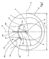
図1は船体30の後方の下部領域の背面図を示す。船尾管として構成される軸受け31はおよそ水平線方向において船体30から船尾へ突出する。図1の図面において、軸受け31は図面の平面あるいはこれの中から外に向かう。プロペラシャフト(図示されていない)はプロペラ軸線32に沿っており、軸受け31に取り付けられる。図1の図面において、プロペラ軸線32もまた図面の平面又はこれの中から外に向かっている。進行方向で流れ案内面部50の下流に位置し且つ図面の外側であるため、プロペラ33はプロペラ円の概略が示されるだけである。この船舶はいわゆる単一プロペラ船舶であるため、1つのプロペラ33をもつだけである。
FIG. 1 shows a rear view of the lower region behind the
流れ案内面部50はプロペラ33のプロペラ上流から離れて配置されている。更に、流れ案内面部50は板形で構成されており、そのためプロペラ軸線32と平行な平面に延長されている。図1に示される流れ案内面部50は、プロペラ軸線32から一定距離54に位置する。
The flow
図1に示されている装置100は流れ案内面部50から外側に突き出ている2つの第1フィン50aをもつ。これら2つの第1フィン50aのそれぞれは第1端部501で流れ案内面部50に接続されている。第1フィン50aのそれぞれの第2端部502は自由な端部として構成されている。更に、図1に示される装置は第2フィン51aをもつ。この第2フィン51aは第1端部503で流れ案内面部50に接続されている。第2フィン51aの第2端部504は軸受け31に接続されている。
The
図2は船体30の後方領域の背面図を示す。図2による装置は、流れ案内面部50が弓形に構成されているという点だけが図1による装置とは異なる。
FIG. 2 shows a rear view of the rear area of the
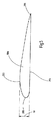
図3は船舶の下部船尾部分の側面図を示す。船体30の船尾からおおよそ水平に突き出ている軸受け31は、プロペラシャフト(図示されていない)が配置されている船尾管として構成されている。プロペラシャフトはプロペラ軸線32に沿っている。プロペラ33は軸受け31の端部に備えられている。更に、プロペラ33の進行方向上流において、流れ案内面部50はプロペラ33から離れて且つプロペラ33の上流に示されている。更に、外側又は上方に突き出ている第1フィン50aは流れ案内面部50の上に位置している。第1フィン50aは、第2端部502が自由な状態にある端部として構成されるのに対して、当該弓形に形成された流れ案内面部50の上部領域に第1端部501で接続している。
FIG. 3 shows a side view of the lower stern portion of the ship. A bearing 31 projecting substantially horizontally from the stern of the
図4は装置100の更なる実施形態の斜視図を示す。この装置100は周方向で開いているように構成された前方ノズル10と、4つの外部フィン20a〜20dと同様に4つの内部フィン21a〜21dとを含む。それぞれのフィン20aと21a、20bと21b、20cと21c、20dと21dが対となり、完全フィンを形成する。ゆえに、図4によれば、流れ案内面部50は開いているノズルリングとして構成されている。このノズルリングはおおよそ円周の3分の2が閉じられたノズルに対応するため、開いているノズルリングはいわゆる3分の2ノズルに対応する。更に、図9に対する説明も参照する。図9は同様の実施形態を示すけれども、図4に示される実施形態と対照的である円周方向で閉鎖されるように構成されている前方ノズル10を図9の装置100が示す。
FIG. 4 shows a perspective view of a further embodiment of the
図5はフィンの実施例の横断面図を示す。示されたフィンは原則として第1フィン50a又は第2フィン51aの断面図である。図5に示された例では、示されたフィンが第1フィン50aである。フィン50aは、図5のトップに配置されたカーブした吸込み側部203と、その反対側に配置されたおおよそ平面の圧力側部204とをもつ。フィン50aの前縁の部分を形成する丸い前面205は、前方ノズル10に取り付けられた状態で流れの中に置かれるのが望ましい。つまり、上流に配置される。その効果に、フィン50aの後縁部分を形成するおおよそ尖った裏面206(すなわち形状端部)は前方ノズル10に取り付けられた状態でプロペラ流動の下流に置かれるのが望ましい。
FIG. 5 shows a cross-sectional view of an embodiment of the fin. The fins shown are in principle sectional views of the
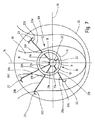
図6は船体30の後方の下部領域の背面図を示す。軸受け31はおおよそ水平方向で船体30から船尾に突き出る船尾管として構成される。図6の図面では、軸受け31は図面の平面あるいはこれの中から外に向かう。プロペラシャフト(図示されていない)はプロペラ軸線32に沿っており、軸受け31に取り付けられる。図6の図面において、プロペラ軸線32もまた図面の平面又はこれの中から外に向かっている。プロペラ軸線32はプロペラ軸線32について同心に配置される前方ノズル10の長手方向軸線を同時に形成する。好適な本実施形態の前方ノズル10は回転対称体であることが示されているため、プロペラ軸線32は前方ノズル10の回転軸線を同時に形成する。進行方向で前方ノズル10の下流に位置し且つ図面の外側であるため、プロペラ33はプロペラ円の概略が示されるだけである。この船舶はいわゆる単一プロペラ船舶であるため、1つのプロペラ33をもつだけである。
FIG. 6 shows a rear view of the lower region behind the
前方ノズル10は周方向で閉鎖しており、内部壁表面12と外部ノズル壁表面13とで構成されるノズル壁11をもつ。垂直中心線34及び水平中心線35はプロペラ33を通るように描かれている。前方ノズル10はプロペラ33に同心で配置されるため、中心線34,35は前方ノズル10のための中心線でもある。プロペラ軸線32は2つの中心線34,35の交差する点に位置する。垂直中心線34による前方ノズル10の仮想分割において、左半分の前方ノズルは前方ノズル10のプロペラ上方ビート側部14であり、右半分の前方ノズルは前方ノズル10のプロペラ下方ビート側部15である。
The
軸受け31と前方ノズル壁11の内側12との間にわたるように配置される内部フィン21a,21b,21cのそれぞれは(右回りプロペラに関して)、前方ノズル10のプロペラ上方ビート側部14に提供される。軸受け31と前方ノズル壁11との間にわたるもう1つの内部フィン21dはプロペラ下方ビート側部15に取り付けられており、特に水平中心線15の上にある。内部フィン21a,21b,21c,21dはそれぞれ軸受け31と前方ノズル10に固定される。4つの外部フィン20a,20b,20c,20dは前方ノズル10の外ノズル壁表面13から外へ突出している。外部フィン20a,20b,20c,20dはそれぞれ内部フィン21a,21b,21c,21dの延長に配置されている。外部フィン20a,20b,20c,20dとまた内部フィン21a,21b,21c,21dとはプロペラ軸線32又は前方ノズルの回転軸線の放射状に全て配置されており、そのためプロペラ軸線32の放射方向にある。個々のフィン20aと21a、20bと21b、20cと21c、20dと21dのペアはそれぞれで完全なフィンを形成する。すなわち、それらは連続的なフィンとしておおよそ流体学的な役割を果たすが、事実上前方ノズル10によって遮られ、その上、それぞれが固定される(例えば、溶接されるか前方ノズルに溶接される)。それによって、装置100は比較的大きな長さの完全なフィンで高い安定性を獲得する。
Each of the
全体的に3つの完全なフィンはプロペラ上方ビート側部14に、そして1つの完全なフィンプロペラが下方ビート側部15に配置されている。プロペラ下方ビート側部15で特に水平中心線35の下方に、軸受け31と前方ノズル10との間にあり且つそれら両方に接続されている安定化支柱22が更に提供されている。安定化支柱22は圧縮又は伸張棒としての役割を果たし且つ船体に前方ノズル10を安定して固定されるような方法で構成されている。安定化支柱22はフィンとして構成されない。つまり、水中翼又は同種のものをもっていないが、少しばかり流動に影響を与えることができる。安定化支柱22は、フィン20a,20b,20c,20d、21a,21b,21c,21dと比較してより大きな形状厚さをもつ。
Overall, three complete fins are located on the
外部フィン20a,20b,20c,20dのそれぞれは前方ノズル10の外部壁表面13に配置され、前方ノズル10に接続される第1端部201をもつ。外部フィンはまた第1端部201の反対側に自由端として構成される第2端部202をもつ。フィン端部小片23は第2端部202から横に突き出る。図6の図面では、フィン端部小片23は吸込み側部を形成する外部フィン20a,20b,20cの下側にそれぞれ向かっている。外部フィン20dの自由端202に備えられている2つのフィン端部小片23は互いに対照的に配置されている。1つのフィン端部小片23は外部フィン20dの上方側に向かって突き出ており、1つのフィン端部小片23は外部フィン20dの下方側に向かって突き出ている。フィン端部小片23は「ウイングレット(winglets)」として作用し、外部フィン20a,20b,20c,20dの自由端202の領域のいわゆる分離乱流及びキャビテーションを減らす。フィン端部小片23のそれぞれは半径方向において外部フィン20a,20b,20c,20dをそれぞれ越えている。
Each of the
図7は図6と同様である。図7による実施形態では、図6と異なり、前方ノズル10の長手方向軸線として同時に形成される回転軸16を備える前方ノズル10がプロペラ軸線32に対して上方にシフトしている。したがって、図6に図示されている内部フィン21a,21b,21c,21dが同じ長さをもつのに対して、内部フィン21a,21b,21c,21dは異なる長さをもつ。安定化支柱22は図6の実施形態と比較して短くなっている。その上、図6に図示されている外部フィン20a,20b,20c,20dがそれぞれ同じ長さをもつのに対して、図7の図面では外部フィン20a,20b,20c,20dは異なる長さをもつ。図6の実施形態及び図7の実施形態の両方において、プロペラ33の半径は完全なフィンの長さ(最も長い)よりそれぞれの場合で長い。図7の図面では、最大完全フィン(例えば、外部フィン20cと内部フィン21cとで構成される)の長さは図6の完全なフィンより長い。
FIG. 7 is similar to FIG. In the embodiment according to FIG. 7, unlike FIG. 6, the
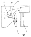
図8は船舶の下部の船尾部分の側面図を示す。プロペラシャフト(図示されていない)に配置されている船尾管として構成される軸受け31は、船体30の船尾からおおよそ水平に突き出している。プロペラシャフトはプロペラ軸線32に沿っている。プロペラ33は軸受け31の端部に備えられている。前方ノズル10は進行方向でプロペラ33の前方にさらに備えられている。回転軸線又は長手方向軸線16は回転対称の前方ノズル10を通って中心に走っている。前方ノズル10はプロペラ軸線32に対して回転軸線16で上方にシフトされている。更に、回転軸線16はプロペラ軸線32に対して斜めに傾いている。すなわち、進行方向から視認した場合、前方ノズル10は上方エッジ領域の先を行くことで整列されているか配置されている。プロペラ軸線32に対して前方へ且つ下方へ傾斜しているか傾けられている。前方ノズルの上方領域では、外部フィン20が前方ノズルから外に突出している。進行方向で視認した場合、外部フィン20はプロペラ33に直面する前方ノズル10の後方領域に位置している。船舶を操縦するための舵(ラダー)36は進行方向でプロペラ33の下流に備えられている。
FIG. 8 shows a side view of the lower stern portion of the ship. A bearing 31 configured as a stern tube disposed on a propeller shaft (not shown) projects substantially horizontally from the stern of the
図9は本発明によるもう1つの実施形態の装置10の斜視図を示す。装置100は、周方向でそれ自身が閉じられたノズルリング又は前方ノズル10と、フィン20aと21a、20bと21b、20cと21c、20dと21dのペアがそれぞれで完全なフィンを形成する4つの外部フィン20a〜20d及び4つの内部フィン21a〜21dとをまた含む。個々のフィン20a〜20d;21a〜21dはそれぞれ、図5に示されるような横断面図をもつ。特に、フィン20a〜20d;21a〜21dのそれぞれは、吸込み側部203及び圧力側部204を含む。フィン20a〜20d;21a〜21dは前方ノズルの後方領域にそれぞれ配置されている。図9の図面では個々のフィン20a〜20d;21a〜21dが前方ノズル10に接続されている状態で連続的に示されていない。進行方向37で視認した場合、外部フィン20a〜20d及び内部フィン21a〜21d両方が前方ノズル10の前方領域に配置されている。特に、進行方向から視認した場合、後方領域は前方ノズル10の全長の70%以下、好ましくは55%以下である。前方ノズル10は、外部フィン20a〜20d及び内部フィン21a〜21dがそれぞれ完全に同一であると識別できるように、図9において透けて見えている。
FIG. 9 shows a perspective view of another embodiment of the
外部フィン20a〜20dの第2端部202のそれぞれに付属しているフィン端部小片23は、板形で構成されており、外部フィン20a〜20dから片側へ横に突き出ている。外部フィン20a〜20dの先のエッジか前面205に直面している板として構成されるフィン端部小片23のエッジ231は、前方ノズル10の主な流動方向18に対して横に且つ少し斜めに後方へ配置されている。フィン端部小片23の2つの側面エッジ232は、主な流動方向18に対して実質的に直角に位置するフィン端部小片23の後縁233に対して主な流動方向18におおよそ並列に整列されている。外部フィン20a〜20dの長手方向に関して、フィン端部小片23は90度から120度の角度で外へ突出する。右回りプロペラの場合では、フィン端部小片23はプロペラの回転方向で外部フィン20a〜20dから横に突き出る。図9の装置100では、内部フィン21a〜21dは外部フィン20a〜20dよりもそれぞれ大きい長さをもつ。更に、全ての外部フィン20a〜20dは、それらの長さ、厚さ、及び奥行きに関して同じ寸法をもち、形状も同じである。内部フィン21a〜21dにも同様である。内部フィン21a〜21dは同じ長さをもつため、前方ノズル10の回転軸線又は長手方向軸線はプロペラ軸線と同軸上に配置されている。すなわち、2つの軸線は他方の軸線に位置する。
The
内部フィン21a〜21dが非湾曲であるのに対して、外部フィン20a〜20dは湾曲されるように構成される。これは図9の装置100の側面図である図10の図面において詳細に見ることができる。前方ノズル10の回転軸線又は長手方向軸線16は図10の図面に示されている。回転軸線16に対して第1上方突出直角線17a及び第2下方突出直角線17bが図示されている。内部フィン21a〜21dが明確に識別できるように、前方ノズル10は図10で透視されている。さらに、内部フィン21bの前縁205は直角線17aに対して実質的に平行に配置されていることが識別し得る。内部フィン21dの後縁206もまた直角線17bに対して実質的に平行に配置されていることが識別し得る。内部フィン21b〜21dは同じ構成であるため、これらの平行配置は全ての内部フィン21b〜21dに適用する。すなわち、主な流動方向18で視認する場合か進行方向37で視認する場合、内部フィン21b〜21dの奥行きは内部フィン21b〜21dの長さにわたって実質的に一定である。内部フィン21b〜21dは非湾曲であるように構成される。
The
これと対照的に、外部フィン20b〜20dは湾曲され、特に前縁曲線をもつよう構成される。したがって、外部フィン20bの前縁エッジ205は直角線17aと湾曲角度βで配置されている。結果、これは同じ構成の残っている外部フィンに適用される。外部フィン20b〜20dの後縁206は、外部フィン20b〜20dの後縁が非湾曲であり、そのために直角線対して傾いていないように、直角線17a、17bに実質的に平行に整列されている。したがって、進行方向37で視認した場合、外部フィン20b〜20dの奥行きは第1端部201から第2端部202に向かって減少する。前縁205が直線であるため、一方の端部201から他方の端部202まで連続的である。図10に図示されていない外部フィン20aと内部フィン21aとは、他の内部フィン21b〜21d及び他の外部フィン20b〜20dと同様に構成される。
In contrast, the
更に、前方ノズル10の外径は主な流動方向18で連続的に減少することが図10で見出すことができる。同じく、前方ノズル10の内径は主な流動方向18で減少するが、側面図において内部の前方ノズル壁表面11が弓形の形状であるため、連続的ではない。
Furthermore, it can be seen in FIG. 10 that the outer diameter of the
図11は図9及び10と同様に構成された本発明による装置100のもう1つの実施形態を示す。特にこの装置は、それぞれ1つの完全なフィンを形成する4つの外部フィン20a〜20d及び4つの内部フィン21a〜21dを含む。図11の実施形態と図9及び10の実施形態の両方は、前方ノズル10内に1及び2つの完全なフィンが非対称に配置される。
FIG. 11 shows another embodiment of the
図9及び10による実施形態とは対照的に図11の実施形態では、外部フィン20a〜20dの第2端部203がフィン端部小片23との間に所定角度で配置されない。しかし、半径をもつ遷移部23aを備えている。更に図11では、完全フィンが前方ノズル10を通過している。すなわち、図9及び10の実施形態では完全なフィンが2つの部品で形成され且つ内部フィン及び外部フィンのそれぞれに分割されて前方ノズル10に固定されているのに対して、完全なフィンは1つの部品として形成されている。図9及び10による実施形態に対して図11による実施形態のもう1つの差異は、内部フィン21a〜21d及び外部フィン20a〜20dの両方が本質的に湾曲して構成されていることである。ここで、フィンの前縁だけが湾曲される場合では、後縁は湾曲されない。内部フィン21a〜21dの前縁の湾曲は、一定の角度の連続的な前縁エッジ曲線が得られるように、外部フィン20a〜20dの回転軸線に直交する線に対して同じ角度をなしている。
In the embodiment of FIG. 11, in contrast to the embodiment according to FIGS. 9 and 10, the second ends 203 of the
更に図11では、特に進行方向37で船体30の後方に装置100が船体30に取り付けられることが識別される。
11 also identifies that the
100 装置
10 前方ノズル
11 前方ノズル壁
12 内部前方ノズル壁表面
13 外部前方ノズル壁表面
14 プロペラ上方ビート側部
15 プロペラ下方ビート側部
16 前方ノズルの回転軸線
17 回転軸線に対する直角線
18 主流動方向
20,20a,20b,20c,20d 外部フィン
201 外部フィンの第1端部
202 外部フィンの第2端部
203 吸込み側部
204 圧力側部
205 前面
206 裏面
21,21a,21b,21c,21d 内部フィン
22 安定化支柱
23 フィン端部小片
23a 遷移部
30 船舶の船体
31 軸受け
32 プロペラ軸線
33 プロペラ
34 垂直中心線
35 水平中心線
36 ラダー
37 進行方向
50 流れ案内面部
50a 第1フィン
51 流れ案内面部の形状厚さ
51a 第2フィン
52 形状入口エッジ
53 形状出口エッジ
54 流れ案内面部とプロペラ軸線との間の距離
55 プロペラ直径
501 第1フィンの第1端部
502 第1フィンの第2端部
503 第2フィンの第1端部
504 第2フィンの第2端部
α 回転軸線とプロペラ軸線との間の交差角
β 湾曲角度
20, 20a, 20b, 20c,
50
α Intersection angle between rotation axis and propeller axis β Bending angle
Claims (24)
前記第1フィン(20a,20b,20c,20d,50a)の第1端部(201,501)は前記流れ案内面部(50)に固定されており、前記第1フィン(20a,20b,20c,20d,50a)の第2端部(202,502)は自由端として構成されており、
プロペラ軸線(32)と前記第1フィン(20a,20b,20c,20d,50a)の前記第1端部(201,501)との間の距離は、前記プロペラ軸線(32)と前記第1フィン(20a,20b,20c,20d,50a)の前記第2端部(202,502)との間の距離よりも短く、
前記プロペラ軸線(32)と前記第1フィン(20a,20b,20c,20d,50a)の前記第2端部(202,502)との間の距離はプロペラ(33)の半径以下であり、
少なくとも1つの第2フィン(21a,21b,21c,21d,51a)が前記流れ案内面部(50)から突出し、前記第2フィン(21a,21b,21c,21d,51a)の第1端部(503)は前記流れ案内面部(50)に配置されており、前記第2フィン(21a,21b,21c,21d,51a)は船体上及び/又は船舶の前記プロペラ(33)のプロペラシャフトを取り付けるために配置される軸受け(31)上に第2端部(504)で固定され、
前記第1フィン(20a,20b,20c,20d,50a)の長さは前記第2フィン(21a,21b,21c,21d,51a)の長さの少なくとも1.5倍であり、
前記第1フィン及び/若しくは前記第2フィン(20a,20b,20c,20d,50a,21a,21b,21c,21d,51a)は、それぞれプロペラ下方ビート側部(15)よりもプロペラ上方ビート側部(14)に多く存在し、又は前記第1フィン及び/若しくは前記2フィン(20a,20b,20c,20d,50a,21a,21b,21c,21d,51a)は、それぞれ非対称フィン系を構成するように配置されることを特徴とする船舶の所要駆動力を減らすための装置。 A flow guide surface (50), at least one first fin (20a, 20b, 20c, 20d, 50a) protruding from said flow guide surface (50);
First ends (201, 501) of the first fins (20a, 20b, 20c, 20d, 50a) are fixed to the flow guide surface portion (50), and the first fins (20a, 20b, 20c, 20d, 50a) are configured as free ends (202, 502),
The distance between the propeller axis (32) and the first end (201, 501) of the first fin (20a, 20b, 20c, 20d, 50a) is determined by the distance between the propeller axis (32) and the first fin. (20a, 20b, 20c, 20d, 50a) shorter than the distance between the second ends (202, 502);
The distance between the propeller axis (32) and the second end (202, 502) of the first fin (20a, 20b, 20c, 20d, 50a) is less than or equal to the radius of the propeller (33);
At least one second fin (21a, 21b, 21c, 21d, 51a) protrudes from the flow guide surface (50), and a first end (503) of the second fin (21a, 21b, 21c, 21d, 51a). ) Are disposed on the flow guide surface portion (50), and the second fins (21a, 21b, 21c, 21d, 51a) are provided for mounting a propeller shaft of the propeller (33) on a hull and / or a ship. Fixed on a bearing (31) to be arranged at a second end (504),
The length of the first fins (20a, 20b, 20c, 20d, 50a) is at least 1.5 times the length of the second fins (21a, 21b, 21c, 21d, 51a);
The first fins and / or the second fins (20a, 20b, 20c, 20d, 50a, 21a, 21b, 21c, 21d, 51a) each have a propeller upper beat side (15) than a propeller lower beat side (15). (14), the first fin and / or the second fin (20a, 20b, 20c, 20d, 50a, 21a, 21b, 21c, 21d, 51a) each constitute an asymmetric fin system. A device for reducing the required driving force of a ship, wherein the device is arranged in a ship.
前記第1フィン(20a,20b,20c,20d,50a)の第1端部(201,501)は前記流れ案内面部(50)に固定されており、前記第1フィン(20a,20b,20c,20d,50a)の第2端部(202,502)は自由端として構成されており、
プロペラ軸線(32)と前記第1フィン(20a,20b,20c,20d,50a)の前記第1端部(201,501)との間の距離は、前記プロペラ軸線(32)と前記第1フィン(20a,20b,20c,20d,50a)の前記第2端部(202,502)との間の距離よりも短く、
少なくとも1つの第2フィン(21a,21b,21c,21d,51a)が前記流れ案内面部(50)から突出し、前記第2フィン(21a,21b,21c,21d,51a)の第1端部(503)は前記流れ案内面部(50)に配置されており、前記第2フィン(21a,21b,21c,21d,51a)は船体上及び/又は船舶のプロペラ(33)のプロペラシャフトを取り付けるために配置される軸受け(31)上に第2端部(504)で固定され、
前記第1フィン(20a,20b,20c,20d)は前記第2フィン(21a,21b,21c,21d)の延長に配置されており、両方が一緒になって完全なフィンを形成し、前記完全なフィンの長さは前記プロペラ(33)の半径の最大90%であり、
前記第1フィン(20a,20b,20c,20d,50a)の長さは前記第2フィン(21a,21b,21c,21d,51a)の長さの少なくとも1.5倍であり、
前記第1フィン及び/若しくは前記第2フィン(20a,20b,20c,20d,50a,21a,21b,21c,21d,51a)は、それぞれプロペラ下方ビート側部(15)よりもプロペラ上方ビート側部(14)に多く存在し、又は前記第1フィン及び/若しくは前記2フィン(20a,20b,20c,20d,50a,21a,21b,21c,21d,51a)は、それぞれ非対称フィン系を構成するように配置されることを特徴とする船舶の所要駆動力を減らすための装置。 A flow guide surface (50), at least one first fin (20a, 20b, 20c, 20d, 50a) protruding from said flow guide surface (50);
First ends (201, 501) of the first fins (20a, 20b, 20c, 20d, 50a) are fixed to the flow guide surface portion (50), and the first fins (20a, 20b, 20c, 20d, 50a) are configured as free ends (202, 502),
The distance between the propeller axis (32) and the first end (201, 501) of the first fin (20a, 20b, 20c, 20d, 50a) is determined by the distance between the propeller axis (32) and the first fin. (20a, 20b, 20c, 20d, 50a) shorter than the distance between the second ends (202, 502);
At least one second fin (21a, 21b, 21c, 21d, 51a) protrudes from the flow guide surface (50), and a first end (503) of the second fin (21a, 21b, 21c, 21d, 51a). ) Are disposed on the flow guide surface portion (50), and the second fins (21a, 21b, 21c, 21d, 51a) are disposed on the hull and / or for mounting a propeller shaft of a propeller (33) of the ship. Fixed at a second end (504) on a bearing (31) to be
The first fins (20a, 20b, 20c, 20d) are arranged as extensions of the second fins (21a, 21b, 21c, 21d), and together form a complete fin, The length of the fin is at most 90% of the radius of the propeller (33),
The length of the first fins (20a, 20b, 20c, 20d, 50a) is at least 1.5 times the length of the second fins (21a, 21b, 21c, 21d, 51a);
The first fins and / or the second fins (20a, 20b, 20c, 20d, 50a, 21a, 21b, 21c, 21d, 51a) each have a propeller upper beat side (15) than a propeller lower beat side (15). (14), the first fin and / or the second fin (20a, 20b, 20c, 20d, 50a, 21a, 21b, 21c, 21d, 51a) each constitute an asymmetric fin system. A device for reducing the required driving force of a ship, wherein the device is arranged in a ship.
Applications Claiming Priority (3)
| Application Number | Priority Date | Filing Date | Title |
|---|---|---|---|
| DE202013101943U DE202013101943U1 (en) | 2013-05-06 | 2013-05-06 | Device for reducing the power requirement of a watercraft |
| DE202013101943.7 | 2013-05-06 | ||
| PCT/EP2014/056412 WO2014180605A1 (en) | 2013-05-06 | 2014-03-31 | Device for reducing the driving power requirement of a watercraft |
Publications (3)
| Publication Number | Publication Date |
|---|---|
| JP2016520474A JP2016520474A (en) | 2016-07-14 |
| JP2016520474A5 JP2016520474A5 (en) | 2017-05-18 |
| JP6678575B2 true JP6678575B2 (en) | 2020-04-08 |
Family
ID=48784199
Family Applications (1)
| Application Number | Title | Priority Date | Filing Date |
|---|---|---|---|
| JP2016512256A Active JP6678575B2 (en) | 2013-05-06 | 2014-03-31 | Equipment for reducing the required driving force of ships |
Country Status (16)
| Country | Link |
|---|---|
| US (1) | US10005530B2 (en) |
| EP (1) | EP2994379B1 (en) |
| JP (1) | JP6678575B2 (en) |
| KR (3) | KR102412435B1 (en) |
| CN (2) | CN203958582U (en) |
| CA (1) | CA2911459C (en) |
| DE (1) | DE202013101943U1 (en) |
| DK (1) | DK2994379T3 (en) |
| ES (1) | ES2737453T3 (en) |
| HK (1) | HK1219080A1 (en) |
| HR (1) | HRP20190973T1 (en) |
| PL (1) | PL2994379T3 (en) |
| SG (1) | SG11201509192TA (en) |
| TR (1) | TR201908084T4 (en) |
| TW (1) | TWI637881B (en) |
| WO (1) | WO2014180605A1 (en) |
Families Citing this family (9)
| Publication number | Priority date | Publication date | Assignee | Title |
|---|---|---|---|---|
| DE202013101943U1 (en) * | 2013-05-06 | 2013-06-11 | Becker Marine Systems Gmbh & Co. Kg | Device for reducing the power requirement of a watercraft |
| DE102015103285A1 (en) | 2015-03-06 | 2016-09-08 | Becker Marine Systems Gmbh & Co. Kg | Arrangement for multi-propeller ships with external propeller shafts and method for producing such an arrangement |
| CN104828226A (en) * | 2015-04-21 | 2015-08-12 | 中国船舶工业集团公司第七〇八研究所 | Auxiliary propulsion energy-saving device for ship hydrodynamics |
| JP6239711B1 (en) * | 2016-09-15 | 2017-11-29 | サノヤス造船株式会社 | Ship duct equipment |
| SE544385C2 (en) * | 2019-09-23 | 2022-05-03 | Volvo Penta Corp | Propeller combination for a marine vessel |
| WO2021239963A1 (en) * | 2020-05-28 | 2021-12-02 | Becker Marine Systems Gmbh | Arrangement for reducing a drive power requirement of a watercraft |
| CN114379752B (en) * | 2021-12-09 | 2022-08-26 | 南通海国机械有限公司 | Leading guide pulley of prewhirling for boats and ships |
| FI20225121A1 (en) * | 2022-02-11 | 2023-08-12 | Kongsberg Maritime Finland Oy | A flow guide arrangement of a rectracable thruster, a rectracable thruster, and a system |
| WO2024025376A1 (en) * | 2022-07-27 | 2024-02-01 | 에이치디한국조선해양 주식회사 | Ship structure |
Family Cites Families (23)
| Publication number | Priority date | Publication date | Assignee | Title |
|---|---|---|---|---|
| JPS5332594A (en) * | 1976-09-07 | 1978-03-27 | Hitachi Zosen Corp | Ship |
| JPS595680Y2 (en) * | 1980-07-22 | 1984-02-20 | 三菱重工業株式会社 | Ship propulsion performance improvement device |
| JPS60139699U (en) * | 1984-02-29 | 1985-09-14 | 三菱重工業株式会社 | Marine nozzle device |
| US5292088A (en) * | 1989-10-10 | 1994-03-08 | Lemont Harold E | Propulsive thrust ring system |
| US5634613A (en) * | 1994-07-18 | 1997-06-03 | Mccarthy; Peter T. | Tip vortex generation technology for creating a lift enhancing and drag reducing upwash effect |
| US5906522A (en) * | 1998-04-01 | 1999-05-25 | Hooper; Robert P. | Thrust enhancer for marine propeller |
| KR100394464B1 (en) | 2000-12-01 | 2003-08-09 | 현대중공업 주식회사 | Y-shaped stator |
| US7267589B2 (en) * | 2004-07-22 | 2007-09-11 | Enviroprop Corporation | System and apparatus for improving safety and thrust from a hydro-drive device |
| KR100625847B1 (en) * | 2004-10-14 | 2006-09-20 | 부산대학교 산학협력단 | Asymmetric Pre-swirl Stator for Cavitation Suppression |
| KR100640299B1 (en) * | 2005-04-14 | 2006-10-30 | 대우조선해양 주식회사 | Installation structure for preswirl stator of ship |
| JP4717857B2 (en) * | 2007-06-14 | 2011-07-06 | 住友重機械マリンエンジニアリング株式会社 | Ship duct and ship |
| DE202008006069U1 (en) | 2008-03-10 | 2008-07-17 | Becker Marine Systems Gmbh & Co. Kg | Device for reducing the power requirement of a ship |
| TW201010908A (en) * | 2008-09-02 | 2010-03-16 | Jen-Chen Tuan | Easily operable aircraft |
| JP2010195153A (en) | 2009-02-24 | 2010-09-09 | Mitsubishi Heavy Ind Ltd | Reaction fin device for ship and ship |
| KR101023052B1 (en) | 2009-09-17 | 2011-03-24 | 대우조선해양 주식회사 | Ducted pre-swirl stator |
| KR20120068250A (en) | 2010-12-17 | 2012-06-27 | 현대중공업 주식회사 | Duct structure for ship |
| DE202011000439U1 (en) * | 2011-02-25 | 2012-08-21 | Becker Marine Systems Gmbh & Co. Kg | Pre-nozzle for a propulsion system of a watercraft to improve energy efficiency |
| KR101334217B1 (en) * | 2011-05-03 | 2013-11-29 | 에스피피조선 주식회사 | Fuel-efficiecy Improving crown duct for ship |
| KR101723240B1 (en) * | 2011-05-13 | 2017-04-18 | 현대중공업 주식회사 | Propeller Duct Structure of Ship with Multi-Column Fin |
| CN202244050U (en) | 2011-08-17 | 2012-05-30 | 上海船舶研究设计院 | Reaction fin in front of oar |
| DE102011053619A1 (en) * | 2011-09-14 | 2013-03-14 | Becker Marine Systems Gmbh & Co. Kg | Propeller nozzle for watercraft |
| PL2591994T3 (en) * | 2011-11-11 | 2015-03-31 | Becker Marine Sys Gmbh & Co Kg | Device for lowering the fuel consumption of the propulsion of a watercraft |
| DE202013101943U1 (en) * | 2013-05-06 | 2013-06-11 | Becker Marine Systems Gmbh & Co. Kg | Device for reducing the power requirement of a watercraft |
-
2013
- 2013-05-06 DE DE202013101943U patent/DE202013101943U1/en not_active Expired - Lifetime
- 2013-12-14 CN CN201320835028.8U patent/CN203958582U/en not_active Expired - Lifetime
-
2014
- 2014-03-31 ES ES14717112T patent/ES2737453T3/en active Active
- 2014-03-31 EP EP14717112.8A patent/EP2994379B1/en active Active
- 2014-03-31 SG SG11201509192TA patent/SG11201509192TA/en unknown
- 2014-03-31 WO PCT/EP2014/056412 patent/WO2014180605A1/en active Application Filing
- 2014-03-31 KR KR1020217002742A patent/KR102412435B1/en active IP Right Grant
- 2014-03-31 TR TR2019/08084T patent/TR201908084T4/en unknown
- 2014-03-31 DK DK14717112.8T patent/DK2994379T3/en active
- 2014-03-31 KR KR1020227020830A patent/KR102512176B1/en active IP Right Grant
- 2014-03-31 US US14/889,491 patent/US10005530B2/en active Active
- 2014-03-31 CN CN201480036775.2A patent/CN105452100B/en active Active
- 2014-03-31 CA CA2911459A patent/CA2911459C/en active Active
- 2014-03-31 JP JP2016512256A patent/JP6678575B2/en active Active
- 2014-03-31 PL PL14717112T patent/PL2994379T3/en unknown
- 2014-03-31 KR KR1020157034659A patent/KR20160031452A/en not_active Application Discontinuation
- 2014-05-05 TW TW103115913A patent/TWI637881B/en active
-
2016
- 2016-06-20 HK HK16107077.3A patent/HK1219080A1/en unknown
-
2019
- 2019-05-28 HR HRP20190973TT patent/HRP20190973T1/en unknown
Also Published As
| Publication number | Publication date |
|---|---|
| EP2994379A1 (en) | 2016-03-16 |
| US10005530B2 (en) | 2018-06-26 |
| KR20220092633A (en) | 2022-07-01 |
| TW201502008A (en) | 2015-01-16 |
| KR102412435B1 (en) | 2022-06-23 |
| KR20160031452A (en) | 2016-03-22 |
| CN203958582U (en) | 2014-11-26 |
| WO2014180605A1 (en) | 2014-11-13 |
| TWI637881B (en) | 2018-10-11 |
| EP2994379B1 (en) | 2019-05-01 |
| ES2737453T3 (en) | 2020-01-14 |
| HRP20190973T1 (en) | 2019-07-26 |
| JP2016520474A (en) | 2016-07-14 |
| HK1219080A1 (en) | 2017-03-24 |
| DK2994379T3 (en) | 2019-06-03 |
| TR201908084T4 (en) | 2019-06-21 |
| KR20210024140A (en) | 2021-03-04 |
| CA2911459A1 (en) | 2014-11-13 |
| PL2994379T3 (en) | 2019-09-30 |
| CN105452100A (en) | 2016-03-30 |
| US20160090163A1 (en) | 2016-03-31 |
| CA2911459C (en) | 2019-10-15 |
| DE202013101943U1 (en) | 2013-06-11 |
| SG11201509192TA (en) | 2015-12-30 |
| CN105452100B (en) | 2022-01-28 |
| KR102512176B1 (en) | 2023-03-21 |
Similar Documents
| Publication | Publication Date | Title |
|---|---|---|
| JP6678575B2 (en) | Equipment for reducing the required driving force of ships | |
| JP5357319B2 (en) | Device for reducing ship driving force requirements | |
| JP6212027B2 (en) | Pre-nozzles for watercraft drive systems to improve energy efficiency | |
| US9789943B2 (en) | Arrangement for multi screw vessels comprising external propeller shafts as well as method for producing such an arrangement | |
| JP6138680B2 (en) | Duct equipment | |
| KR102531811B1 (en) | Stern geometry and vessel with stern duct | |
| KR20230094685A (en) | Pre-swirl stator having coanda effect | |
| JP2017226308A (en) | Reaction fin device | |
| JP5511869B2 (en) | Asymmetrical front wing of a ship |
Legal Events
| Date | Code | Title | Description |
|---|---|---|---|
| A521 | Request for written amendment filed |
Free format text: JAPANESE INTERMEDIATE CODE: A523 Effective date: 20170327 |
|
| A621 | Written request for application examination |
Free format text: JAPANESE INTERMEDIATE CODE: A621 Effective date: 20170327 |
|
| A131 | Notification of reasons for refusal |
Free format text: JAPANESE INTERMEDIATE CODE: A131 Effective date: 20180220 |
|
| A601 | Written request for extension of time |
Free format text: JAPANESE INTERMEDIATE CODE: A601 Effective date: 20180521 |
|
| A521 | Request for written amendment filed |
Free format text: JAPANESE INTERMEDIATE CODE: A523 Effective date: 20180720 |
|
| A131 | Notification of reasons for refusal |
Free format text: JAPANESE INTERMEDIATE CODE: A131 Effective date: 20190108 |
|
| A521 | Request for written amendment filed |
Free format text: JAPANESE INTERMEDIATE CODE: A523 Effective date: 20190404 |
|
| A131 | Notification of reasons for refusal |
Free format text: JAPANESE INTERMEDIATE CODE: A131 Effective date: 20190910 |
|
| TRDD | Decision of grant or rejection written | ||
| A01 | Written decision to grant a patent or to grant a registration (utility model) |
Free format text: JAPANESE INTERMEDIATE CODE: A01 Effective date: 20200218 |
|
| A61 | First payment of annual fees (during grant procedure) |
Free format text: JAPANESE INTERMEDIATE CODE: A61 Effective date: 20200317 |
|
| R150 | Certificate of patent or registration of utility model |
Ref document number: 6678575 Country of ref document: JP Free format text: JAPANESE INTERMEDIATE CODE: R150 |
|
| R250 | Receipt of annual fees |
Free format text: JAPANESE INTERMEDIATE CODE: R250 |
|
| R250 | Receipt of annual fees |
Free format text: JAPANESE INTERMEDIATE CODE: R250 |