KR20160031452A - Device for reducing the driving power requirement of a watercraft - Google Patents
Device for reducing the driving power requirement of a watercraft Download PDFInfo
- Publication number
- KR20160031452A KR20160031452A KR1020157034659A KR20157034659A KR20160031452A KR 20160031452 A KR20160031452 A KR 20160031452A KR 1020157034659 A KR1020157034659 A KR 1020157034659A KR 20157034659 A KR20157034659 A KR 20157034659A KR 20160031452 A KR20160031452 A KR 20160031452A
- Authority
- KR
- South Korea
- Prior art keywords
- pin
- flow
- guiding surface
- propeller
- nozzle
- Prior art date
Links
Images


Classifications
-
- B—PERFORMING OPERATIONS; TRANSPORTING
- B63—SHIPS OR OTHER WATERBORNE VESSELS; RELATED EQUIPMENT
- B63H—MARINE PROPULSION OR STEERING
- B63H1/00—Propulsive elements directly acting on water
- B63H1/02—Propulsive elements directly acting on water of rotary type
- B63H1/12—Propulsive elements directly acting on water of rotary type with rotation axis substantially in propulsive direction
- B63H1/14—Propellers
- B63H1/28—Other means for improving propeller efficiency
-
- B—PERFORMING OPERATIONS; TRANSPORTING
- B63—SHIPS OR OTHER WATERBORNE VESSELS; RELATED EQUIPMENT
- B63H—MARINE PROPULSION OR STEERING
- B63H5/00—Arrangements on vessels of propulsion elements directly acting on water
- B63H5/07—Arrangements on vessels of propulsion elements directly acting on water of propellers
- B63H5/16—Arrangements on vessels of propulsion elements directly acting on water of propellers characterised by being mounted in recesses; with stationary water-guiding elements; Means to prevent fouling of the propeller, e.g. guards, cages or screens
-
- F—MECHANICAL ENGINEERING; LIGHTING; HEATING; WEAPONS; BLASTING
- F04—POSITIVE - DISPLACEMENT MACHINES FOR LIQUIDS; PUMPS FOR LIQUIDS OR ELASTIC FLUIDS
- F04D—NON-POSITIVE-DISPLACEMENT PUMPS
- F04D29/00—Details, component parts, or accessories
- F04D29/40—Casings; Connections of working fluid
-
- B63B2745/02—
-
- Y—GENERAL TAGGING OF NEW TECHNOLOGICAL DEVELOPMENTS; GENERAL TAGGING OF CROSS-SECTIONAL TECHNOLOGIES SPANNING OVER SEVERAL SECTIONS OF THE IPC; TECHNICAL SUBJECTS COVERED BY FORMER USPC CROSS-REFERENCE ART COLLECTIONS [XRACs] AND DIGESTS
- Y02—TECHNOLOGIES OR APPLICATIONS FOR MITIGATION OR ADAPTATION AGAINST CLIMATE CHANGE
- Y02T—CLIMATE CHANGE MITIGATION TECHNOLOGIES RELATED TO TRANSPORTATION
- Y02T70/00—Maritime or waterways transport
- Y02T70/50—Measures to reduce greenhouse gas emissions related to the propulsion system
-
- Y02T70/542—
Abstract
본 발명은 적어도 하나의 제1 핀(20)이 돌출되는 흐름 안내 표면(10)을 포함하는 워터크래프트의 구동 출력 요건을 감소시키기 위한 디바이스(100)에 관한 것이다. 상기 제1 핀의 제1 단부는 상기 흐름 안내 표면(10)에 고정되고, 상기 제1 핀의 제2 단부는 자유단으로 구현된다.The present invention relates to a device (100) for reducing the driving power requirement of a watercraft comprising a flow guiding surface (10) from which at least one first pin (20) projects. A first end of the first fin is fixed to the flow guiding surface (10), and a second end of the first fin is embodied as a free end.

Description
본 발명은 워터크래프트, 특히 선박의 구동 출력 요건을 감소시키기 위한 디바이스에 관한 것이다. 본 발명에 따른 디바이스는 특히 워터크래프트의 구동 시스템에서 에너지 효율을 개선하기에 적합하다.The present invention relates to a watercraft, in particular a device for reducing the driving output requirements of a ship. The device according to the invention is particularly suitable for improving the energy efficiency in the drive system of the watercraft.
워터크래프트의 구동 출력 요건을 감소시키기 위한 디바이스들은 선행 기술들로부터 공지된다. EP 2 100 808 A1에서 그러한 디바이스는 예를 들어 포어-노즐(fore-nozzle)을 포함한다. 이러한 포어-노즐은 특히 선박의 이동 방향으로 보일 때 프로펠러의 바로 상류 또는 짧은 거리를 두고 장착된다. 게다가, 핀들, 즉 (가이드) 핀들 또는 하이드로포일들(hydrofoils)이 포어-노즐 내에 제공된다. 포어-노즐은 실질적으로 편평한 단면의 형상을 구비하고, 이때 양쪽 개구들, 물 입구 및 물 출구 개구 모두는 실질적으로 원형 개구로 구성되고 물 입구 개구는 물 출구 개구보다 큰 직경을 구비한다. 결과적으로, 포어-노즐 내에 설치된 핀들에 의해 예-선회(pre-swirl)의 구체적인 발생에 의해 프로펠러 제트 내에 손실들을 감소시키고 프로펠러 유입을 개선할 수 있다. 구동 출력 요건 내 상당한 감소 및 연소 절감이 그러한 시스템에 의해 달성될 수 있다.Devices for reducing the driving output requirements of a watercraft are known from the prior art. Such a device in EP 2 100 808 A1 includes for example a fore-nozzle. These for-nozzles are mounted just upstream or short distances from the propeller, especially when viewed in the direction of movement of the ship. In addition, fins, i.e. (guide) pins or hydrofoils are provided in the pore-nozzle. The pore-nozzle has a substantially flat cross-sectional shape, wherein both openings, both the water inlet and the water outlet opening are substantially circular openings and the water inlet opening has a larger diameter than the water outlet opening. As a result, it is possible to reduce the losses in the propeller jet and improve the propeller flow by the specific occurrence of the pre-swirl by the pins installed in the pore-nozzle. Significant reduction in burnout power and combustion savings can be achieved by such a system.
그러나 전술된 이미 공지된 디바이스는 프로펠러 유입에 대하여 상대적으로 큰 저항을 구비하여 적절한 정도로 구동 출력 요건 내 감소는 주로 오직 더 느리거나 더 무겁게 실린 선박들에서 제공될 수 있고, 공지된 디바이스는 보통 그러한 선박들에서만 사용된다.However, the already-known devices described above have a relatively large resistance to propeller inflow, so that a reduction in drive power requirement to an adequate degree can only be provided in ships which are mainly only slower or heavier, .
그러므로 본 발명의 목적은 특히 효율적으로 빠르고 매우 빠른 워터크래프트, 예를 들어 20 knots 이상 또는 25 knots 이상의 속도를 구비하는 선박들에서 또한 사용될 수 있는 워터크래프트의 구동 출력 요건을 감소시키기 위한 디바이스를 제공하는 것이다.It is therefore an object of the present invention to provide a device for reducing the drive output requirements of a watercraft which can also be used in ships which are particularly efficient and fast and very fast, for example with a speed of more than 20 knots or more than 25 knots will be.
이러한 목적은 워터크래프트의 구동 출력 요건을 감소시키기 위한 디바이스에서, 흐름-안내 디바이스를 포함하고, 제1 핀의 제1 단부가 흐름-안내 디바이스에 장착되고 제1 핀의 제2 단부가 자유단으로 구성되는 방식으로 적어도 하나의 제1 핀이 흐름-안내 디바이스로부터 돌출되는 것에 의해 해결된다.This object is achieved in a device for reducing the driving output requirement of a watercraft, comprising a flow-guiding device, wherein a first end of the first fin is mounted to the flow-guiding device and a second end of the first fin is a free end Wherein at least one first pin protrudes from the flow-guiding device in a manner so constructed.
흐름-안내 표면은 흐름-안내 표면을 형성하기 위해 하나의 부품 또는 하나의 피스(piece)로 형성되거나 복수 개의 개별적인 부품들로 이루어질 수 있고, 이때 개별적인 부품들은 바람직하게 서로에 대해 용접되거나 헐(hull)에 용접된다.The flow-guiding surface can be formed of a single part or a piece or of a plurality of individual parts to form a flow-guiding surface, wherein the individual parts are preferably welded to each other or hulled ).
흐름-안내 표면은 이론적으로 모든 가능한 형상들을 구비할 수 있다. 동시에, 흐름-안내 표면은 물 흐름이 프로펠러 위로 적어도 부분적으로 그것에 의해 안내될 수 있는 방식으로 배치되고 구성된다. 예를 들어, 흐름-안내 표면은 정사각형 또는 직사각형 플레이트의 형상을 구비할 수 있다. 게다가, 아치형 또는 구부러진 구성들이 실현 가능할 수 있다. 단면도에서, 아치형으로-구성된 흐름-안내 표면은 원형 구획, 타원형 구획, 또는 구부러진 형상을 구비할 수 있다. 흐름-안내 표면은 흐름 방향으로, 예를 들어 워터크래프트의 이동 방향으로 길이를 구비한다. 게다가, 플레이트-형상으로 된 구성에서, 흐름-안내 표면은 폭을 구비하거나, 아치형 구성에서, 호 길이를 구비한다. 흐름-안내 표면의 두께는 이하에서 프로파일 두께로 정해진다. 길이 및 폭 또는 호 길이 및 프로파일 두께는 흐름-안내 표면의 전체 영역에 대하여 일정할 수 있거나 그것들은 다른 값들을 구비할 수 있다. 예를 들어, 흐름-안내 표면은 또한 프로파일될(profiled) 수 있다. 이러한 경우에, 예를 들어, 흐름-안내 표면의 하나의 가장자리는 둥글게 구성될 수 있고 흐름-안내 표면의 중앙 영역보다 더 얇은 프로파일 두께를 구비할 수 있다.The flow-guiding surface may theoretically have all possible shapes. At the same time, the flow-guiding surface is arranged and constructed in such a way that the water flow can be guided at least partly by the propeller over it. For example, the flow-guiding surface may have the shape of a square or rectangular plate. In addition, arcuate or curved configurations may be feasible. In the cross-sectional view, the arcuately-constructed flow-guiding surface may have a circular section, an elliptical section, or a curved shape. The flow-guiding surface has a length in the direction of flow, for example in the direction of movement of the watercraft. In addition, in a plate-like configuration, the flow-guiding surface may have a width or, in an arcuate configuration, have a arc length. The thickness of the flow-guiding surface is defined by the profile thickness in the following. The length and width or arc length and profile thickness may be constant for the entire area of the flow-guiding surface or they may have different values. For example, the flow-guiding surface may also be profiled. In this case, for example, one edge of the flow-guiding surface may be rounded and may have a profile thickness that is thinner than the central region of the flow-guiding surface.
본 발명에 따라, 제1 핀은 흐름-안내 표면에 적절한 방식으로 제1 단부에 연결되고, 또는 흐름-안내 표면에 장착된다. 예를 들어, 제1 핀은 제1 단부에서 흐름-안내 표면에 용접되거나 플랜지-고정될 수 있다. 본 발명에 따라 제1 핀의 제2 단부는 자유단으로 구성된다. 결론적으로, 제1 핀은 임의의 방향으로 흐름-안내 표면으로부터 돌출될 수 있고, 이때 제1 핀의 제2 단부는 흐름-안내 표면에 연결되지 않거나 다른 방법으로 선박들의 헐에 장착된다. "핀(fin)"이라는 용어는 바람직하게 흐름-안내 표면 상에 고정되게 배치된 하이드로포일 또는 가이드 핀으로 이해되는 것이다. 동시에, "핀"이라는 용어는 프로펠러 유입(inflow)에 영향을 미치는 가이드 디바이스로서 이해될 수 있고, 이때 핀은 보통 하이드로포일 프로파일, 즉 석션 및 압력 측을 구비한다. 따라서, 본 연결에서 핀들은 프로펠러 유입에 영향을 미치고 흐름-안내 표면 상에 배치된 스테이터들(stators)의 관점에서 흐름 안내 표면들이다. 특히, 핀들은 특히 원형-호-형상으로 된(circular-arc-shaped), 외측으로 구부러진 석션 측 및 실질적으로 편평한 압력 측을 구비하는 것이 바람직하다.According to the invention, the first pin is connected to the first end in a suitable manner on the flow-guiding surface, or is mounted on the flow-guiding surface. For example, the first fin can be welded or flanged-fixed to the flow-guiding surface at the first end. According to the present invention, the second end of the first fin is configured as a free end. Consequently, the first pin can protrude from the flow-guiding surface in any direction, wherein the second end of the first pin is not connected to the flow-guiding surface or otherwise mounted on the hull of the vessel. The term "fin" is understood to be a hydrofoil or guide pin fixedly disposed on a flow-guiding surface. At the same time, the term "pin" can be understood as a guide device which influences propeller inflow, wherein the pin usually has a hydrofoil profile, i.e. suction and pressure side. Thus, the fins in this connection are flow guiding surfaces in terms of stators that influence propeller inflow and are placed on the flow-guiding surface. In particular, the fins preferably have a circular-arc-shaped, outwardly curved suction side and a substantially flat pressure side.
제1 핀의 프로파일은 그것의 길이에 대하여 관측될 때 균일하거나 다르게 될 수 있다. 특히, 프로파일은 제1 핀의 길이방향을 따라 보일 때, 그 자체 안으로 턴될(turned) 수 있으며, 즉 비틀릴 수 있다(twisted). 결론적으로, 흐름-안내 표면과 함께 제1 핀 또한 물 흐름을 위해 안내 표면으로서 작용하고, 이때 흐름-안내 표면 및 제1 핀은 서로에 대해 각이 지게 배치되고, 바람직하게 제1 핀은 흐름-안내 표면보다 더 작게 구성된다. 제1 핀의 길이는 제1 핀의 제1 단부 및 제2 단부 사이의 거리인 것으로 이해된다. 제1 핀의 깊이는 흐름-안내 표면의 길이방향으로, 즉 워터크래프트의 이동 방향으로 핀의 깊이인 것으로 이해된다. 핀의 두께는 이하에서 프로파일 두께로서 정해진다.The profile of the first fin may be uniform or different when viewed relative to its length. In particular, when the profile is viewed along the longitudinal direction of the first pin, it may be turned into itself, i. E., Twisted. Consequently, the first fin together with the flow-guiding surface also serves as a guiding surface for water flow, wherein the flow-guiding surface and the first fin are angularly disposed relative to each other, Is configured to be smaller than the guide surface. The length of the first fin is understood to be the distance between the first end and the second end of the first fin. The depth of the first fin is understood to be the depth of the fin in the longitudinal direction of the flow-guiding surface, i.e. in the direction of movement of the watercraft. The thickness of the fin is defined below as the profile thickness.
본 발명의 관점에서 제1 핀은 흐름-안내 표면으로부터 돌출되고 흐름-안내 표면에 제1 단부와 연결되고 제2 단부는 자유단인 모든 핀들로서 이해된다. 바람직하게 다수의 그러한 제1 핀들이 제공될 수 있다.In the context of the present invention, a first fin is understood as all pins which protrude from the flow-guiding surface and are connected to the first end on the flow-guiding surface and the second end is a free end. Preferably, a plurality of such first pins may be provided.
바람직하게, 흐름-안내 표면은 프로펠러의 상류에 배치된다. 이는 흐름-안내 표면이 워터크래프트, 또는 선박의 이동 방향으로, 워터크래프트의 프로펠러의 상류에 배치된다는 것을 의미한다. "이동 방향으로(in the direction of travel)"라는 지정은 여기에서 선박 또는 워터크래프트의 이동의 전방 방향으로 이해된다.Preferably, the flow-guiding surface is disposed upstream of the propeller. This means that the flow-guiding surface is disposed in the watercraft, or in the direction of movement of the vessel, upstream of the propeller of the watercraft. The designation "in the direction of travel" is understood here as the forward direction of movement of the ship or watercraft.
이러한 경우에, 흐름-안내 표면이 프로펠러로부터 이격되어 위치되는 것이 더 제공된다. 게다가, 흐름-안내 표면은 샤프트 베어링, 특히 스턴 튜브로부터 이격되어 위치되는 것이 바람직하다. 스턴 튜브는 워터크래프트 또는 선박의 프로펠러의 프로펠러 샤프트를 장착하기 위해 사용된다. 이를 위해 흐름-안내 표면은 적어도 구획들에서 프로펠러 축 위, 아래 또는 또한 측방향으로(laterally) 배치될 수 있다. 게다가, 흐름-안내 표면은 샤프트 베어링 또는 프로펠러 축을 적어도 부분적으로 감쌀 수 있다. 특히 바람직하게 흐름-안내 표면은 프로펠러 샤프트 또는 프로펠러 축으로부터 이격되어 그리고 위에 아치형으로 배치된다. 이러한 경우에, 아치형으로 구성된 흐름-안내 표면은 또한 원주 방향으로 폐쇄되도록 구성될 수 있다. 바람직하게 그러나, 아치형 흐름-안내 표면은 1/8 링(eighth ring), 1/4 링(quarter ring)의 단면을 구비한다. 흐름-안내 표면은 1/2 링, 2/3 링 또는 3/4 링의 단면을 구비하는 것이 더 바람직하다.In this case it is further provided that the flow-guiding surface is located apart from the propeller. In addition, the flow-guiding surface is preferably spaced apart from the shaft bearing, especially the stern tube. The stern tube is used to mount the propeller shaft of a watercraft or ship propeller. To this end, the flow-guiding surface may be arranged laterally above, below or even at least in the sections of the propeller shaft. In addition, the flow-guiding surface may at least partially wrap the shaft bearing or propeller shaft. Particularly preferably, the flow-guiding surface is arranged apart from the propeller shaft or the propeller shaft and arcuately above it. In this case, the arcuately constructed flow-guiding surface may also be configured to be closed in the circumferential direction. Preferably however, the arcuate flow-guiding surface has an eighth ring, a quarter ring cross-section. It is further preferred that the flow-guiding surface has a cross-section of 1/2 ring, 2/3 ring or 3/4 ring.
게다가, 흐름-안내 표면은 아치형이고 원주 방향으로 개방되게 구성될 수 있고, 이때 흐름-안내 표면은 원형 단면을 구비지 않으나, 예를 들어 타원형 단면을 구비한다. 바람직하게 흐름-안내 표면은 프로펠러 축에 대해 볼록하도록 구성된다.Furthermore, the flow-guiding surface can be configured to be arcuate and open in the circumferential direction, wherein the flow-guiding surface does not have a circular cross-section but has, for example, an elliptical cross-section. Preferably the flow-guiding surface is configured to be convex with respect to the propeller shaft.
흐름-안내 표면의 아치형 구성의 경우에, 단면도에서 흐름-안내 표면의 호 길이는 개념상으로 원주 방향으로(circumferentially) 폐쇄된 흐름-안내 표면의 원주(circumference)의 바람직하게 80%보다 작은, 특히 바람직하게 60%보다 작은, 특히 바람직하게 40% 또는 30%보다 작다.In the case of the arcuate configuration of the flow-guiding surface, the arc length of the flow-guiding surface in the cross-section is preferably less than 80% of the circumference of the circumferentially closed flow-guiding surface, , Preferably less than 60%, particularly preferably less than 40% or 30%.
이론적으로, 그러나 다른 단면들 또한 실현 가능하다. 예를 들어, 흐름-안내 표면은 각진, 예를 들어 직사각형 단면을 구비할 수 있다. 게다가 흐름-안내 표면의 U-형상으로 된 구성이 실현 가능하다.In theory, however, other cross sections are also feasible. For example, the flow-guiding surface may have an angled, e.g. rectangular, cross-section. Furthermore, a U-shaped configuration of the flow-guiding surface is feasible.
흐름-안내 표면 상에 제1 핀의 배치의 결과, 제1 핀의 제1 단부가 흐름-안내 표면에 장착되고 제1 핀의 제2 단부가 자유단으로 구성되는 경우, 흐름-안내 표면의 프로파일 두께 및/또는 호 길이 또는 폭 또는 길이 같은 치수들이 종래 기술로부터 공지된 디바이스들에 비해 상당히 감소될 수 있고, 그렇지만 흐름 손실들이 특히 높고 효과적인 작동을 위해 선회(swirl)가 산출되어야 하는 영역들이 여전히 제1 핀에 의해 획득될 수 있다.As a result of the arrangement of the first fin on the flow-guiding surface, when the first end of the first fin is mounted on the flow-guiding surface and the second end of the first fin is constituted as a free end, Dimensions such as thickness and / or arc length or width or length can be significantly reduced compared to devices known from the prior art, but the areas where the flow losses are particularly high and the swirl is to be calculated for effective operation, 1 < / RTI > pins.
게다가, 흐름-안내 표면으로부터 시작하는 제1 핀의 제2 단부가 프로펠러 축으로부터 멀리 향해지는 것이 바람직하다. 그것은 제1 핀의 제1 단부로부터 프로펠러 축으로의 거리가 제1 핀의 제2 단부(자유단)로부터 프로펠러 축으로의 거리보다 짧다는 것을 의미한다.In addition, it is desirable that the second end of the first fin starting from the flow-guiding surface be directed away from the propeller shaft. Which means that the distance from the first end of the first pin to the propeller shaft is less than the distance from the second end (free end) of the first pin to the propeller shaft.
결과적으로, 흐름-안내 표면은 프로펠러 샤프트로부터 이격되어 배치될 수 있고, 이때 프로펠러 샤프트 및 흐름-안내 표면 사이의 거리는 종래 기술에 비해 더 짧다. 제1 핀이 그것의 제2 단부가 프로펠러 축으로부터 멀리 향해지는 방식으로 흐름-안내 표면으로부터 돌출되므로, (프로펠러 샤프트로부터 방사상 방향으로 보일 때) 제1 핀이 프로펠러 샤프트로부터 충분히 멀리 연장하고, 따라서 개별적으로 연관된 프로펠러 상으로 유입에 여전히 긍정적으로 영향을 미칠 수 있다는 것이 더 보장된다.As a result, the flow-guiding surface can be spaced apart from the propeller shaft, wherein the distance between the propeller shaft and the flow-guiding surface is shorter than in the prior art. Since the first pin projects from the flow-guiding surface in such a way that its second end is directed away from the propeller shaft, the first pin extends sufficiently far from the propeller shaft (when viewed radially from the propeller shaft) Is still more positively impacted on the influx into the associated propeller.
흐름-안내 표면에 핀을 장착하는 것에 의해, 흐름-안내 표면으로부터 프로펠러 샤프트로의 거리 및 흐름-안내 표면의 프로파일 두께 및 그 결과 저항이 감소될 수 있어, 디바이스는 또한 빠르고 매우 빠른 선박들에 대하여 사용될 수 있고 이때 구동 출력 조건의 감소에 대하여 긍정적인 효과들이 여전히 보존되거나 임의적으로 더 개선된다. 제1 핀은 가능한 프로펠러 허브 또는 스턴 튜브로부터가 아닌 흐름-안내 표면으로부터 외측으로 돌출되고, 이는 프로펠러 축으로부터 보일 때 상대적으로 더 외측으로 연장할 수 있지만 여전히 특히 굽힘 응력들에 대하여, 충분한 강도를 구비할 수 있다.By mounting the pins on the flow-guiding surface, the distance from the flow-guiding surface to the propeller shaft and the profile thickness of the flow-guiding surface and the resulting resistance can be reduced, so that the device is also fast And the positive effects for the reduction of the drive output condition are still preserved or optionally further improved. The first pin protrudes outwardly from the flow-guiding surface, but not from a possible propeller hub or stern tube, which can extend relatively more outwardly when viewed from the propeller shaft, but still has sufficient strength against bending stresses can do.
바람직하게 제1 핀은 최대 프로파일 두께를 구비하고, 이때 제1 핀의 최대 프로파일 두께는 제1 핀의 제1 단부 및 제2 단부 사이의 거리의 50%보다 작은, 특히 바람직하게 25%보다 작은, 보다 특히 바람직하게 15%보다 작다. 그러므로 가장 두꺼운 지점에서 제1 핀의 프로파일 두께는 그것의 제1 단부 및 그것의 제2 단부 사이에서 제1 핀의 길이보다 작다.Preferably the first fin has a maximum profile thickness wherein the maximum profile thickness of the first fin is less than 50%, particularly preferably less than 25% of the distance between the first and second ends of the first fin, Even more preferably less than 15%. The profile thickness of the first fin at the thickest point is therefore less than the length of the first pin between its first end and its second end.
이론적으로, 흐름-안내 표면은 프로펠러 샤프트에 평행하거나 프로펠러 축에 평행하게 배치될 수 있다. 이는 흐름-안내 표면 및 프로펠러 축 사이의 거리가 각각의 영역에서 실질적으로 동일하다는 것을 의미한다. 바람직하게 그러나 흐름-안내 표면은 전방을 향해 또는 후방을 향해 프로펠러 축에 대하여 경사지게 배치된다. 이러한 경우에, 흐름-안내 표면은 바람직하게 프로파일되도록 구성될 수 있다. 그러므로 흐름-안내 표면은 프로펠러로부터 멀리 향해지는 프로파일 입구 가장자리를 구비하고 프로파일 입구 가장자리 상에서 물 흐름은 워터크래프트의 이동 방향에서 이동의 전방 방향으로 악영향을 미친다. 흐름-안내 표면의 프로파일 출구 가장자리는 프로펠러를 향해 향해진다. 그러므로 프로파일 입구 가장자리 및 프로파일 출구 가장자리는 흐름-안내 표면의 두 개의 전방-측 가장자리들(front-side edges)을 포함한다. 후방을 향해 프로펠러 축에 대하여 경사진 흐름-안내 표면의 경우에, 프로펠러 축 및 흐름-안내 표면 사이의 거리는 프로파일 출구 가장자리의 영역 내에서 보다 프로파일 입구 가장자리의 영역 내에서 더 크다. 흐름-안내 표면의 그러한 배치의 결과, 프로펠러 위로 유입은 특히 특정 영역들 내에서 바람직하게 영향을 미치도록 될 수 있다. 프로펠러 축에 대해 경사지게 배치된 흐름-안내 표면의 경우에, 흐름-안내 표면의 길이방향 축은 프로펠러 축에 평행하지 않고 각이 지게 나아가고 결과적으로 프로펠러 축에 대하여 경사진다.Theoretically, the flow-guiding surface may be parallel to the propeller shaft or parallel to the propeller shaft. This means that the distance between the flow-guiding surface and the propeller shaft is substantially the same in each region. Preferably, however, the flow-guiding surface is disposed obliquely with respect to the propeller shaft towards the front or rear. In this case, the flow-guiding surface can be configured to be preferably profiled. The flow-guiding surface therefore has a profile inlet edge that is directed away from the propeller and the water flow on the profile inlet edge adversely affects the forward direction of movement in the direction of movement of the watercraft. The profile exit edge of the flow-guiding surface is directed towards the propeller. The profile inlet edge and the profile outlet edge therefore include two front-side edges of the flow-guiding surface. In the case of a flow-guiding surface inclined towards the propeller shaft towards the rear, the distance between the propeller shaft and the flow-guiding surface is greater in the region of the profile inlet edge than in the region of the profile outlet edge. As a result of such an arrangement of the flow-guiding surface, the influx onto the propeller can be particularly effected in certain areas. In the case of a flow-guiding surface arranged obliquely to the propeller shaft, the longitudinal axis of the flow-guiding surface is not parallel to the propeller shaft but angularly and consequently inclined relative to the propeller shaft.
바람직하게 흐름-안내 표면 및 프로펠러 축 사이의 최단 거리는 프로펠러의 반경보다 작거나 프로펠러 직경의 절반보다 작다. 후방을 향해 프로펠러 축에 경사지게 배치된 흐름-안내 표면의 경우에, 흐름-안내 표면의 프로파일 출구 가장자리의 영역 내에서 흐름-안내 표면 및 프로펠러 축 사이의 거리는 프로펠러 직경의 절반보다 짧다.Preferably the shortest distance between the flow-guiding surface and the propeller shaft is less than the radius of the propeller or less than half of the propeller diameter. In the case of a flow-guiding surface disposed obliquely to the propeller shaft towards the rear, the distance between the flow-guiding surface and the propeller shaft in the region of the profile exit edge of the flow-guiding surface is less than half of the propeller diameter.
바람직하게 적어도 하나의 제2 핀은 흐름-안내 표면으로부터 돌출되도록 추가적으로 제공된다. 이러한 경우에, 제2 핀은 제1 단부를 구비하여 흐름-안내 표면 상에 배치되거나 이것에 장착되고 제2 단부를 구비하여 샤프트 베어링, 특히 스턴 튜브 상에 배치되거나 이것에 장착된다. 결과적으로, 흐름-안내 표면으로부터 시작하는 제2 핀은 프로펠러 축을 향해 향해지고 제1 핀과 대조적으로 자유단을 구비하지 않고 헐 또는 샤프트 베어링에 연결된다. 따라서, 제2 핀은 샤프트 베어링으로부터 흐름-안내 표면으로 두 개의 고정된 베어링 지점들 사이에서 나아간다. 두 단부들 사이에서, 제2 핀은 바람직하게 압력 측, 석션 측, 노즈 스트립(nose strip) 및 엔드 스트립(end strip)을 구비한다. 이러한 구성은 또한 흐름-안내 표면으로부터 자유단을 구비하여 외측으로 돌출되는 제1 핀에 대하여 유사하게 적용된다. 헐의 구성에 의존하여, 제2 핀은 샤프트 베어링 대신에, 그것의 제2 단부를 구비하여 헐의 플레이팅(plating) 상에 또는 헐 상에 직접적으로 장착될 수 있다.Preferably at least one second pin is additionally provided to protrude from the flow-guiding surface. In this case, the second pin is disposed on or mounted to the shaft bearing, particularly the stern tube, with a first end disposed or mounted on the flow-guiding surface and having a second end. As a result, the second pin starting from the flow-guiding surface is directed towards the propeller shaft and is connected to the hull or shaft bearing without a free end in contrast to the first pin. Thus, the second pin advances between the two fixed bearing points from the shaft bearing to the flow-guiding surface. Between the two ends, the second fin preferably has a pressure side, a suction side, a nose strip and an end strip. This configuration is also similarly applied to the first pin projecting outwardly with a free end from the flow-guiding surface. Depending on the configuration of the hull, the second pin may be mounted directly on the plating of the hull or on the hull with its second end instead of the shaft bearing.
"제2 핀"은 본 발명의 관점에서 흐름-안내 표면으로부터 돌출되고 그것들의 제1 단부를 구비하여 흐름-안내 표면에 연결되고 그것들의 제2 단부를 구비하여 샤프트 베어링 또는 헐과 연결되는 모든 핀들로서 이해된다. 바람직하게 다수의 그러한 제2 핀들이 제공될 수 있다."Second pin" refers to all the pins that protrude from the flow-guiding surface in the context of the present invention and are connected to the flow-guiding surface with their first ends and which have their second ends connected to the shaft bearing or hull . Preferably a plurality of such second pins may be provided.
게다가 제1 핀 및/또는 제2 핀은 실질적으로 워터크래프트의 구동 프로펠러의 프로펠러 축에 대해 또는 흐름-안내 표면의 길이 방향 축에 대해 방사상 방향으로 배치되는 것이 적당하다. 바람직하게, 양쪽 핀들, 제1 및 제2 핀은 방사상 방향으로 배치된다. 이론적으로, 제1 핀 및 제2 핀은 그것들의 개별적인 접선들에 대하여 다른 각도들로 배치된다. 제1 핀에 대한 접선은 흐름-안내 표면의 외벽 표면 상의 지점을 통해 나아가는 반면 제2 핀에 대한 접선은 흐름-안내 표면의 내벽 표면의 지점을 통해 나아간다. 흐름-안내 표면의 외벽 표면은 프로펠러 샤프트 또는 프로펠러 축으로부터 멀리 향해진 벽 표면으로 이해된다. 반면, 내벽 표면은 프로펠러 샤프트 또는 프로펠러 축을 향해 향해진 흐름-안내 표면의 벽 표면으로 이해된다.Furthermore, it is suitable that the first pin and / or the second pin are arranged substantially in a radial direction with respect to the propeller shaft of the drive propeller of the watercraft or with respect to the longitudinal axis of the flow-guiding surface. Preferably, both fins, the first and second fins are arranged in a radial direction. Theoretically, the first pin and the second pin are disposed at different angles with respect to their respective tangents. The tangent to the first pin goes through a point on the outer wall surface of the flow-guiding surface while the tangent to the second pin goes through a point on the inner wall surface of the flow-guiding surface. The outer wall surface of the flow-guiding surface is understood to be a wall surface directed away from the propeller shaft or propeller shaft. On the other hand, the inner wall surface is understood as the wall surface of the flow-guiding surface directed towards the propeller shaft or propeller shaft.
흐름-안내 표면의 길이방향으로 개별적인 핀들(제1 핀 및 제2 핀)의 연장부(extension)가 흐름-안내 표면의 길이보다 더 작거나 짧은 것이 더 바람직하다. "연장부(Extension)"는 핀들이 흐름-안내 표면의 길이방향으로 늘어나는(stretch) 흐름-안내 표면의 길이방향 프로파일의 길이 또는 영역으로 이해된다. 특히 바람직하게 흐름-안내 표면의 길이방향으로 개별적인 핀들의 연장부는 흐름-안내 표면의 길이의 90%보다 작은, 더 특히 바람직하게 80%보다 작은, 또는 60%보다 작다. 길이방향은 실질적으로 흐름의 방향에 대응한다. 핀들이 실질적으로 흐름-안내 표면의, 프로펠러를 향하는 영역 내인, 후방 영역 내에 배치되는 것이 더 바람직하다. 그러나 이론적으로 길이방향 내 흐름-안내 표면의 전체 연장부에 대한 핀들의 구성 또는 이동 방향에 대한 핀들의 중앙 또는 전방 배치 또한 가능하다.It is further preferred that the extensions of the individual pins (first pin and second pin) in the lengthwise direction of the flow-guiding surface are smaller or shorter than the length of the flow-guiding surface. "Extension" is understood as the length or area of the longitudinal profile of the flow-guiding surface in which the fins stretch in the longitudinal direction of the flow-guiding surface. Particularly preferably, the extensions of the individual pins in the lengthwise direction of the flow-guiding surface are less than 90% of the length of the flow-guiding surface, more particularly preferably less than 80%, or less than 60%. The longitudinal direction substantially corresponds to the direction of flow. It is further preferred that the fins are disposed in the rear region, substantially within the region of the flow-guiding surface facing the propeller. However, it is theoretically possible to arrange the fins to the entire extension of the flow-guiding surface in the longitudinal direction, or to center or forward the fins relative to the direction of movement.
제1 및 제2 핀의 개별적인 두 개의 제1 단부들은 흐름-안내 표면 상에 장착된다. 바람직하게, 제1 핀의 제1 단부는 예를 들어 플랜지-장착되는 것에 의해, 흐름-안내 표면의 외벽 표면 상에 장착되거나, 흐름-안내 표면의 벽인, 흐름-안내 표면 프로파일 안으로 안내될 수 있다. 그 대신에 흐름 안내 표면 또는 안내 표면 프로파일을 통해 제1 핀을 안내하는 것 또한 가능하다. 제1 핀의 제1 단부는 제1 핀의 루트(root)를 형성하고 제2 단부는 제1 핀의 팁(tip)을 형성한다.Two separate first ends of the first and second fins are mounted on the flow-guiding surface. Preferably, the first end of the first fin may be mounted on the outer wall surface of the flow-guiding surface or guided into the flow-guiding surface profile, which is the wall of the flow-guiding surface, for example by flange-mounting . It is also possible to guide the first pin through the flow guide surface or the guide surface profile instead. The first end of the first pin forms the root of the first pin and the second end forms the tip of the first pin.
제1 핀에 대하여 설명된 모든 가능한 구성들은 또한 제2 핀의 구성에 유사하게 전달될 수 있고 그 반대이기도 하거나 거기에 적용될 수 있다.All possible configurations described for the first pin can also be similarly transferred to the configuration of the second pin and vice versa or applied thereto.
흐름-안내 표면은 바람직하게 헐에 제2 핀을 통해 연결될 수 있다. 추가적으로 또는 그 대신에, 흐름-안내 표면은 또한 예를 들어 흐름-안내 표면의 아래 또는 위에 위치된 "브라켓들" 또는 유지 클립들 또는 샤프트 브라켓 암들 같은, 추가적인 연결 수단들을 통해 헐에 연결될 수 있다. 샤프트 브라켓은 또한 적어도 특정 영역들에서 핀들로서 구성될 수 있다.The flow-guiding surface can preferably be connected to the hull through a second pin. Additionally or alternatively, the flow-guiding surface may also be connected to the hull through additional connecting means such as, for example, "brackets" or retaining clips or shaft bracket arms located below or above the flow-guiding surface. The shaft bracket may also be configured as fins at least in certain areas.
바람직한 실시예에서, 다수의 제1 핀 제2 핀들이 제공된다. 이는 다수의 핀들이 흐름-안내 표면으로부터 외측으로 돌출되도록 제공되고 그것들이 그것들의 개별적인 제1 단부를 구비하여 흐름-안내 표면에 연결되고 그것들의 개별적인 제2 단부를 구비하여 자유-직립(free-standing)으로 배치된다는 것을 의미한다. 게다가, 다수의 핀들은 그것들의 제1 단부를 구비하여 흐름-안내 표면에 연결되고 그것들의 제2 단부를 구비하여 헐 또는 프로펠러 샤프트에 연결되도록 제공된다. 특히, 동일한 수의 제1 핀들 및 제2 핀들이 제공되는 것이 바람직하다. 이론적으로, 그러나 동일하지 않은 수의 제1 및 제2 핀들을 제공하는 것 또한 가능하다.In a preferred embodiment, a plurality of first pin second pins are provided. Which is provided so that the plurality of pins project outwardly from the flow-guiding surface and which are connected to the flow-guiding surface with their respective first ends and are provided with free-standing ). ≪ / RTI > In addition, the plurality of pins are provided with a first end thereof connected to the flow-guiding surface and having their second end connected to the hull or propeller shaft. In particular, it is desirable to provide the same number of first and second pins. In theory, it is also possible to provide an unequal number of first and second pins.
특히 디바이스는 적어도 세 개의 제1 핀들 및/또는 적어도 세 개의 제2 핀들, 바람직하게 세 개 내지 일곱 개의 제1 핀들 및/또는 세 개 내지 일곱 개의 제2 핀들을 구비하는 것이 바람직하다. 바람직한 실시예에서, 홀수(odd number) 개의 제1 핀들 및/또는 제2 핀들이 제공될 수 있다.In particular, the device preferably comprises at least three first pins and / or at least three second pins, preferably three to seven first pins and / or three to seven second pins. In a preferred embodiment, odd number of first pins and / or second pins may be provided.
더 많은 제1 핀들이 흐름-안내 표면의 프로펠러 하방-비팅 측(downwards-beating side) 상에서 보다 흐름-안내 표면의 프로펠러 상방-비팅 측(upwards-beating side) 상에 제공되고 및/또는 더 많은 제2 핀들이 흐름-안내 표면의 프로펠러 하방-비팅 측 상에서 보다 흐름-안내 표면의 프로펠러 상방-안내 측 상에 제공되는 것이 더 바람직하다. "흐름-안내 표면의 프로펠러 상방-비팅 측(propeller upwards-beating side of the flow-guiding surface)"이라는 용어는 흐름-안내 표면의 정면도에서 흐름-안내 표면의 하류에 배치된 프로펠러가 전방으로 이동할 때 바닥으로부터 상부로 턴(turn)하는 흐름-안내 표면의 측인 것으로 이해된다. 따라서 프로펠러 하방-비팅 측 상에서 프로펠러는 상부로부터 바닥으로 턴한다. 그러므로 본 경우에서 설명된 실시예는 특히 적절하게 흐름-안내 표면에서 사용될 수 있고, 흐름-안내 표면의 중심 길이방향 회전축은 프로펠러 축에 대해 측면으로 변위되지 않고, 대신에 프로펠러 축 상에 수직하게 서 있는 평면 내에 놓여져 중심 수직 축에 의한 흐름-안내 표면의 가상 분할을 구비하여 흐름-안내 표면의 절반은 프로펠러 상방-비팅 측 상에 놓이고 다른 절반은 프로펠러 하방-비팅 측 상에 놓인다.More first pins are provided on the upwards-beating side of the propeller of the flow-guiding surface than on the downwards-beating side of the propeller of the flow-guiding surface and / 2 pins are provided on the guide side of the flow-guiding surface above the propeller lower-butting side of the flow-guiding surface above the propeller of the flow-guiding surface. The term " propeller upwards-beating side of the flow-guiding surface "means that when a propeller disposed downstream of the flow-guiding surface in the front view of the flow- Is understood to be the side of the flow-guiding surface that turns from the bottom to the top. Thus, on the propeller down-side, the propeller turns from top to bottom. The embodiment described in this case is therefore particularly suitable for use in a flow-guiding surface and the center longitudinal axis of rotation of the flow-guiding surface is not displaced laterally with respect to the propeller shaft, Plane with a virtually divided flow-guiding surface by a central vertical axis such that one half of the flow-guiding surface lies on the propeller upper-beating side and the other half lies on the propeller down-beating side.
프로펠러에서 회전 손실을 최소화하고 선박의 헐에 의해 동요된 프로펠러 유입에 의해 안내된 프로펠러 역류 내에서 비틀림(twisting)을 감소시키기 위해, (예-)선회는 흐름의 더 작은 비틀림이 정면에 위치된 핀들을 구비하는 흐름-안내 표면이 없는 프로펠러에 비해 프로펠러 역류 내에 프로펠러의 하류에 생성되는 방식으로 정렬된 흐름-안내 표면 상에 배치된 핀들(제1 핀들 또는 제2 핀들)에 의해 생성된다. 프로펠러 역류의 비틀림은 적어도 하나의 제1 핀 및/또는 적어도 하나의 제2 핀이 프로펠러 하방-비팅 측 상에서 보다 프로펠러 상방-비팅 측 상에 배치된다면 특히 작아진다.In order to minimize the rotational losses in the propeller and to reduce twisting in the propeller backwash guided by propeller inflow caused by the hull of the ship, the swirling (eg) swirls the smaller torsion of the flow in front of the fins (First fins or second fins) arranged on the flow-guiding surface in such a way that they are produced downstream of the propeller in the propeller backwash compared to the propeller without the flow-guiding surface having the flow-guiding surface. The twisting of the propeller backwash is particularly small if at least one first pin and / or at least one second pin is disposed on the propeller up-beating side than on the propeller down-beating side.
프로펠러 상방-비팅 측 및 프로펠러 하방-비팅 측 상에서 제1 핀들 및/또는 제2 핀들 대신에 또는 추가적으로, 제1 핀들 및/또는 제2 핀들은 비대칭 제1 핀 시스템 또는 비대칭 제2 핀 시스템을 형성할 수 있다. 여기서, 비대칭은, 예를 들어 프로펠러 축에 대한 핀들의 각진 배치 및/또는 프로파일 길이, 프로파일 단면 또는 다른 수량 같은 그것들의 치수에 관련된다. 프로펠러 축 상으로 향해진 각진 배치에 관한 비대칭의 경우에, 불균일한 각진 분포는 프로펠러 축으로부터 방사상 방향으로 보일 때 개별적인 제1 핀들 및/또는 제2 핀들의 축들 사이에 생성된다. 흐름-안내 표면의 수직 중심축이 대칭 축으로 사용된다면 비대칭 배치 또한 존재할 수 있다. 이러한 대칭 축은 보통 흐름-안내 표면의 상방-비팅 측 및 하방-비팅 측을 동시에 분할한다. 이는 구성 및 배치하기에 용이한 방식으로 특히 효과적인 제1 핀 시스템 또는 제2 핀 시스템을 초래한다.In place of or in addition to the first pins and / or second pins on the propeller upper side - the beating side and the propeller lower side - the beating side, the first and / or second pins form an asymmetric first pin system or asymmetric second pin system . Here, the asymmetry is related to, for example, the angular arrangement of the pins relative to the propeller shaft and / or their dimensions such as profile length, profile cross section or other quantity. In the case of asymmetry with respect to an angular orientation directed onto the propeller shaft, a non-uniform angular distribution is created between the axes of the respective first and / or second pins when viewed radially from the propeller shaft. If the vertical center axis of the flow-guiding surface is used as the axis of symmetry, asymmetrical placement may also be present. This symmetry axis usually simultaneously splits the upper-beating side and the lower-beating side of the flow-guiding surface. This results in a particularly effective first pin system or second pin system in a manner that is easy to configure and deploy.
추가적으로 바람직한 실시예에서, 적어도 하나의 제1 핀은 적어도 하나의 제2 핀의 연장부에 배치되어, 양쪽이 함께 완전한 핀을 형성한다. 그러므로 예를 들어 제1 핀 및 제2 핀의 길이방향 축들이 실질적으로 서로에 대해 직립할 수 있고 및/또는 제1 핀 및 제2 핀은 공통된 방사상 축 상에 배치된다. 바람직하게 흐름-안내 표면의 내벽 표면 상에 적절하게 배치된, 제2 핀의 제1 단부는 흐름-안내 표면의 외벽 표면 상에 배치된 제1 핀의 제1 단부에 반대되게 위치되어 흐름-안내 표면이 오직 두 개의 핀들 사이에 놓일 수 있다. 이론적으로, 양쪽 단부 영역들은 흐름-안내 표면 안으로 또는 흐름-안내 표면의 프로파일 안으로 각각 안내될 수 있어 서로로부터 오직 약간 이격되거나 서로에 대항하여 맞댈 수 있다. 또한 흐름-안내 표면 내에서 리세스(recess)를 통해 안내되고 하나의 서브섹션(subsection)이 제1 핀을 형성하고 다른 서브섹션이 제2 핀을 형성하는 연속적인 핀을 사용할 수 있다. 두 개의 핀들의 바람직한 배치의 결과로서, 유체적으로(fluidically) 제1 핀의 자유단에 대해 견디는 샤프트 베어링으로부터 적절하게(expediently) 나아가는 단일의 핀이 획득된다. 만약 다수의 제1 핀들 및 제2 핀들, 특히 동일한 개수의 제1 핀들 및 제2 핀들이 제공된다면, 이것들은 각각 바람직하게 핀 쌍들로 배치되고 각각 완전한 핀들을 형성한다. 그러므로 예를 들어, 세 개의 제1 핀들 및 세 개의 제2 핀들은 함께 세 개의 완전한 핀들을 형성할 수 있다.In a further preferred embodiment, the at least one first pin is disposed in the extension of the at least one second pin, and both together form a complete pin. Thus, for example, the longitudinal axes of the first and second fins can be substantially upright relative to each other and / or the first and second fins are disposed on a common radial axis. The first end of the second fin, suitably disposed on the inner wall surface of the flow-guiding surface, is preferably positioned opposite the first end of the first pin disposed on the outer wall surface of the flow- The surface can be placed between only two pins. Theoretically, both end regions can be guided into the flow-guiding surface or into the profile of the flow-guiding surface, respectively, so that they can only be slightly spaced from each other or against each other. It is also possible to use a continuous pin which is guided through a recess in the flow-guiding surface and in which one subsection forms the first fin and the other sub-section forms the second fin. As a result of the preferred arrangement of the two pins, a single pin is obtained which expediently advances fluidly from a shaft bearing that is resistant to the free end of the first pin. If a plurality of first and second pins, particularly the same number of first and second pins, are provided, each preferably is arranged in pairs of pins and each forms a complete pin. Thus, for example, the three first pins and the three second pins together can form three complete pins.
스턴 튜브로부터 방사상으로 돌출하는, 흐름-안내 표면 없는 핀들을 구비하는 배치들 또는 종래 기술로부터 공지된 순수한 스테이터 배치들(pure stator arrangements)에 비해, 전체 배치의 상당히 증가된 강도가 흐름-안내 표면의 제공을 통해 획득된다. 결과적으로, 완전한 핀들은 최상의 가능한 효율을 획득하기 위해 또는 프로펠러 위로 유입에 최적으로 영향을 미치기 위해 담보된 피로 강도(ensured fatigue strength)를 구비하여 충분히 길게 되도록 설계될 수 있다. 흐름-안내 표면이 없이 긴 핀들을 구비하는 종래 기술로부터 공지된 배치들에서, 피로 강도는 종종 획득되지 않는다.The significantly increased strength of the entire arrangement, compared to arrangements with flow-free surface-free fins radially projecting from the stern tube, or with pure stator arrangements known from the prior art, Lt; / RTI > As a result, the complete pins can be designed to be sufficiently long to have the ensured fatigue strength to achieve the best possible efficiency or to optimally influence the influx onto the propeller. In known arrangements from the prior art having long fins without a flow-guiding surface, fatigue strength is often not obtained.
완전한 핀의 길이는 일반적으로 워터크래프트의 프로펠러의 반경보다 크거나 작을 수 있다. 완전한 핀의 길이는 프로펠러 축으로부터 제1 핀의 최외곽 (자유) 단부로 측정되고, 이때 임의적으로 두 개의 핀들(제1 핀 제2 핀) 사이에 배치된 흐름-안내 표면이 또한 포함된다. 바람직하게 완전한 핀의 길이는 프로펠러의 반경의 최대 90%, 특히 바람직하게 최대 오직 75%이다. 그러나 이에 의해 디바이스의 충분한 강도가 획득된다.The length of the complete pin can generally be larger or smaller than the radius of the propeller of the watercraft. The length of the complete pin is measured from the propeller shaft to the outermost (free) end of the first pin, optionally including a flow-guiding surface disposed between the two pins (first pin second pin). Preferably the length of the complete pin is at most 90%, particularly preferably at most 75% of the radius of the propeller. However, sufficient strength of the device is thereby obtained.
추가적으로 바람직한 실시예에서, 제1 핀 및/또는 제2 핀은 프로펠러 축에 대해 방사상으로 어택각에서 배치된다. 특히, 제1 핀 및 제2 핀은 다른 어택각들을 구비할 수 있다. 만약 다수의 제1 핀들 및/또는 제2 핀들이 제공된다면, 이것들은 또한 서로 사이에서 다른 어택각들을 구비할 수 있다. 다른 어택각들을 세팅하는 것에 의해, 예선회를 최적화할 수 있다. 예를 들어, 조절의 각도는 예를 들어, 프로펠러 축 및 단면도에서 핀의 길이방향 축 또는 개별적인 핀의 단부 스트립(end strip)으로 노즈 스트립(nose strip)으로부터 나아가는 코드(chord)에 의해 둘러싸인다.In a further preferred embodiment, the first pin and / or the second pin are arranged at an attack angle radially with respect to the propeller shaft. In particular, the first pin and the second pin may have different attack angles. If a plurality of first pins and / or second pins are provided, they may also have different attack angles between each other. By setting different attack angles, the preliminary time can be optimized. For example, the angle of the adjustment is surrounded by a chord extending from the nose strip to, for example, the longitudinal axis of the pin in the propeller shaft and the cross section, or the end strip of the individual pin.
추가적으로 바람직한 실시예에서 제1 핀은 흐름-안내 표면으로부터 가장 먼 제1 핀의 영역을 형성하는 자유단을 구비한다. 이 자유단 영역에서 핀 단부 피스는 제1 핀으로부터 돌출된다. 그러므로 예를 들어 핀 단부 피스의 길이방향 축은 제1 핀의 길이방향 축에 대해 각이 지게 위치될 수 있다. 본 경우에 "돌출하는 핀 단부 피스(protruding fin end piece)"라는 용어는 일반적으로 제1 핀의 연장부 내에 정확하게 배치되지 않고 제1 핀으로부터 특정 각도로 또는 제1 핀으로부터 비스듬하게 돌출되거나 제1 핀의 허구로(fictitiously) 연장된 프로파일 윤곽으로부터 벗어나는 제1 핀의 자유단 영역 내에 배치된 모든 구성요소들을 의미한다. 그러므로 핀 단부 피스는 핀 평면으로부터 돌출된다. 그러한 돌출하는 핀 단부 피스는 에어크래프트 에어포일들(aerofoils)로부터 공지된 "윙릿들(winglets)"과 유사한 작용을 하고 제1 핀의 단부 영역으로 분리되는 와류들 및 동시에 발생하는 캐비테이션의 가능성을 감소시킨다.In a further preferred embodiment, the first fin has a free end forming an area of the first fin most distant from the flow-guiding surface. In this free end region, the pin end piece protrudes from the first pin. Thus, for example, the longitudinal axis of the pin end piece may be angularly positioned relative to the longitudinal axis of the first pin. In this case, the term "protruding fin end piece" generally refers to a protruding fin end piece that is not exactly positioned within the extension of the first fin and that protrudes obliquely from the first fin at an angle, Refers to all components disposed within the free end region of the first pin that deviate from the fictitiously extended profile contour of the pin. Therefore, the pin end piece protrudes from the pin plane. Such projecting pin end pieces act similar to "winglets" known from the aircraft airfoils and reduce the likelihood of simultaneous cavitation and vortices separating into the end regions of the first fin. .
핀 단부 피스는 방사상으로(at a radius) 제1 핀의 자유단 영역 안으로 나아갈 수 있다. 그 대신에 핀 단부 피스는 제1 핀의 자유단 상에 각이 지게 장착될 수 있어 핀 단부 피스 평면 및 제1 핀이 연장하는 평면은 이 각도에 있다.The pin end piece may be advanced into the free end region of the first pin at a radius. Instead, the pin end piece can be mounted angularly on the free end of the first pin, so that the plane of the pin end piece plane and the first pin extends at this angle.
이론적으로, 핀 단부 피스는 양측들 상에서, 즉 이것으로부터 제1 핀의, 압력 측 및 석션 측 모두 상에, 또는 두 개의 측들 중의 하나 상에서만 돌출될 수 있다. 이전 실시예에서 핀 단부 피스들은 오직 제1 핀의 석션 측을 향해 돌출하는 것이 바람직하며 그 결과 와류 형성의 감소와 관련된 더 큰 유체역학적 효과들이 획득될 수 있다. 핀 단부 피스가 제1 핀의 양쪽 측들 상에서 돌출하거나 튀어나오는 실시예에서, 두 개의 별개의 핀 단부 피스들 또한 제공될 수 있어 각각이 하나의 측 상에 돌출된다. 이론적으로, 그러나 이 실시예에서 핀 단부 피스의 하나의-피스 설계가 가능하다.Theoretically, the pin end piece may protrude only on both sides, i.e. on both the pressure side and the suction side of the first pin, or on one of the two sides. In the previous embodiment, it is preferred that the pin end pieces project only toward the suction side of the first pin and as a result greater hydrodynamic effects associated with the reduction of vortex formation can be obtained. In the embodiment in which the pin end piece protrudes or protrudes on either side of the first pin, two separate pin end pieces may also be provided, each projecting on one side. In theory, however, a one-piece design of the fin end piece is possible in this embodiment.
적어도 하나의 제1 핀 및 적어도 하나의 제2 핀의 존재 시에, 제1 핀이 제2 핀보다 더 큰 길이를 구비하는 것이 더 바람직하다. 특히, 제1 핀의 길이는 제2 핀의 길이의 적어도 1과 1/2 배이고, 바람직하게 적어도 2배로 될 수 있다. 이러한 실시예의 결과로서, 디바이스의 안정성과 관련되고 디바이스 출력 요건과 관련하여 개선된 효과가 획득된다. 이러한 바람직한 실시예에서 길이 분포의 결과, 흐름-안내 표면은 프로펠러 샤프트의 샤프트 베어링에 상대적으로 근접하게 배치되어 디바이스는 상대적으로 낮은 저항을 구비하고 또한 매우 빠른 선박들에서 사용될 수 있다. 그러한, 일반적으로, 제2 핀은 제1 핀보다 더 큰 길이, 예를 들어, 적어도 1과 1/2 배 또는 적어도 2배인 길이를 구비하거나 양쪽 핀들이 대략적으로 동일한 길이를 구비하는 설계가 가능하다.It is further preferred that, in the presence of at least one first pin and at least one second pin, the first pin has a length greater than the second pin. In particular, the length of the first fin may be at least 1 and 1/2 times the length of the second fin, and preferably at least twice. As a result of this embodiment, an improved effect associated with the stability of the device and with respect to device output requirements is obtained. As a result of the length distribution in this preferred embodiment, the flow-guiding surface is disposed relatively close to the shaft bearing of the propeller shaft so that the device has a relatively low resistance and can be used in very fast ships. It is generally possible that the second pin has a length that is greater than the first pin, e.g., at least 1, 1/2, or at least 2 times, or both pins have approximately the same length .
디바이스의 충분히 낮은 저항을 담보하기 위해, 추가적인 실시예에 따라 흐름-안내 표면의 프로파일 두께는 흐름-안내 표면의 길이의 10%보다 크지 않고, 바람직하게 7.5%보다 크지 않고, 특히 바람직하게 6%보다 크지 않도록 제공될 수 있다. 여기서 길이방향으로, 즉 흐름-안내 표면의 프로파일 입구 가장자리로부터 프로파일 출구 가장자리로, 최대 연장부 및 최대 프로파일 두께가 사용되어야 한다. 이러한 수단에 의해, 디바이스의 저항은 또한 더 감소된다.To assure a sufficiently low resistance of the device, the profile thickness of the flow-guiding surface according to a further embodiment is not more than 10%, preferably not more than 7.5%, particularly preferably not more than 6% of the length of the flow- Can be provided so as not to be large. Here, in the longitudinal direction, i.e. from the profile entrance edge of the flow-guiding surface to the profile exit edge, the maximum extension and maximum profile thickness should be used. By this means, the resistance of the device is further reduced.
추가적으로 바람직한 실시예에서, 안정화 스트러트가 더 제공되어 흐름-안내 표면의 내측 및 샤프트 베어링 사이에 배치되고 흐름-안내 표면 및 샤프트 베어링 상에 모두 고정된다. 디바이스의 특별한 구성 또는 국부적인 조건들에 따라, 흐름-안내 표면 또는 디바이스의 추가적인 안정화 또는 유지가 요구된다면 그러한 안정화 스트러트가 제공될 수 있다. 스트러트는 일반적으로 흐름-안내 특성들 없이 노말 압축 또는 인장 로드(normal compression or tension rod)로 구성될 수 있다. 그 대신에, 안전화 스트러트 그 자체는 또한 핀 프로파일, 즉 예를 들어 예선회를 산출하기 위해, 프로펠러 유입에 구체적인 영향을 미치기 위한 하이드로포일 프로파일 또는 유사한 것을 구비할 수 있다.In a further preferred embodiment, a stabilizing strut is further provided to arrange both inside the flow-guiding surface and between the shaft bearings and on both the flow-guiding surface and the shaft bearings. Depending on the particular configuration or local conditions of the device, such stabilization struts may be provided if additional stabilization or maintenance of the flow-guiding surface or device is desired. The strut can generally consist of a normal compression or tension rod without flow-guiding characteristics. Instead, the stabilization strut itself may also have a fin profile, i.e. a hydrofoil profile or the like, to have a specific effect on the propeller inflow to yield a preliminary turn, for example.
제1 핀 및/또는 제2 핀은 추가적으로 스윕되도록(swept) 구성될 수 있다. 특히 항공 주행에서 친숙한, "스윕(swept)"이라는 용어는, 본 문맥에서 흐름-안내 표면의 길이방향 축의 직교선에 대하여 제1 핀 및/또는 제2 핀의 각진 편향(angular deviation)으로 이해된다. 이 경우에, 흐름의 방향으로 보일 때, 핀(제1 핀 및/또는 제2 핀)의 리딩 가장자리(leading edge) 및/또는 트레일링 가장자리(trailing edge)는 직교선(orthogonal)에 대해 각이 지게 경사질 수 있다(이러한 상태는 리딩-가장자리 스윕(leading-edge sweep) 또는 트레일링-가장자리 스윕(trailing-edge sweep)으로 알려져 있다).The first pin and / or the second pin may be configured to be swept further. The term "swept, " which is particularly familiar in air travel, is understood in this context to be an angular deviation of the first pin and / or the second pin with respect to an orthogonal line of the longitudinal axis of the flow- . In this case, when viewed in the direction of flow, the leading edge and / or the trailing edge of the pin (first pin and / or second pin) are angled relative to the orthogonal (This condition is known as a leading-edge sweep or a trailing-edge sweep).
바람직한 실시예에서 오직 제1 핀 및/또는 제2 핀의 리딩 가장자리만이 직교선에 대하여 각이 지게 위치되거나 직교선에 대해 경사지고, 트레일링 가장자리는 대략적으로 직교선에 대하여 평행하게 정렬된다. 또한 제2 핀이 아닌 제1 핀만이 스윕되도록 구성되는 실시예들이 있을 수 있다.In the preferred embodiment, only the leading edges of the first and / or second pins are angled relative to the orthogonal line or are inclined relative to the orthogonal line, and the trailing edge is aligned approximately parallel to the orthogonal line. There may also be embodiments in which only the first pin other than the second pin is swept.
추가적으로 바람직한 실시예에서, 제1 핀 및 제2 핀은 모두 스윕되도록 구성된다. 이는 특히 흐름-안내 표면이 적어도 하나의 완전한 핀을 포함할 때 바람직하며, 이때 완전한 핀은 특히 바람직하게 즉 흐름-안내 표면의 길이방향 축의 직교선에 대하여 제1 핀 및 제2 핀의 리딩 가장자리들 및/또는 트레일링 가장자리들의 동일한 각진 편향들을 구비하여, 연속적으로 스윕되도록 구성된다. In a further preferred embodiment, the first pin and the second pin are both configured to be swept. This is particularly advantageous when the flow-guiding surface comprises at least one complete pin, with the complete pin being particularly preferred, that is to say at the leading edges of the first and second pins relative to the perpendicular line of the longitudinal axis of the flow- And / or with the same angular deflections of the trailing edges.
흐름-안내 표면은 노즐로 구성되고 특히 바람직하게 포어-노즐(fore-nozzle)로 구성되는 것이 더 바람직하다. 이를 위해, 흐름-안내 표면은 프로펠러 위로 구체적으로 흐름을 안내하는 특성을 구비하는 방식으로 형상될 뿐만 아니라 추가적으로 유입 속도가 단면들에서 적어도 증가되는 방식으로 형상된다. 이는, 예를 들어 흐름-안내 표면의 길이방향으로 (단면도에서) 링의 반경이 앞에서 뒤로 프로펠러를 향해 감소하는 아치형으로 구성된 흐름-안내 표면을 구비하여 제공될 수 있다.It is further preferred that the flow-guiding surface consists of a nozzle and particularly preferably consists of a fore-nozzle. To this end, the flow-guiding surface is shaped in such a way that it is shaped in such a manner as to have a characteristic of guiding the flow specifically over the propeller, but additionally in such a manner that the inflow velocity is at least increased in cross-sections. This can be provided, for example, with a flow-guiding surface configured in an arcuate configuration in which the radius of the ring in the longitudinal direction of the flow-guiding surface (in cross-section) decreases from front to back towards the propeller.
포어-노즐은 워터크래프트 또는 선박의 이동 방향으로 워터크래프트의 프로펠러의 상류에 배치된 노즐로 이해된다.The pour-nozzle is understood to be a nozzle arranged upstream of the watercraft or propeller of the watercraft in the direction of movement of the vessel.
바람직한 실시예에서 흐름-안내 표면은 노즐 또는 포어-노즐로 구성되고, 프로펠러는 예를 들어 Kort 노즐들 또는 러더 프로펠러들(rudder propellers)을 제외하고, 노즐 또는 포어-노즐 내에 배치되지 않는다. 게다가, 노즐 또는 포어-노즐 및 노즐로 구성되지 않은 흐름-안내 표면은 프로펠러로부터 이격되어 배치된다. 노즐 또는 포어-노즐은 관통하여 흐르는 물 흐름(through-flowing water flow)이 이후에 위치된 프로펠러 위로 적어도 부분적으로 안내되는 방식으로 구성된다. 보통 노즐 또는 포어-노즐은 튜브 형상을 구비할 것이다. 그러나 다른 단면 형상, 예를 들어 각진 단면 형상 또한 실현 가능하다.In a preferred embodiment, the flow-guiding surface consists of a nozzle or pore-nozzle, and the propeller is not disposed in the nozzle or pore-nozzle, except for, for example, Kort nozzles or rudder propellers. In addition, the flow-guiding surface, which is not composed of nozzles or pore-nozzles and nozzles, is spaced apart from the propeller. The nozzles or pore-nozzles are configured in such a way that a through-flowing water flow is at least partially guided over the subsequently positioned propeller. Usually the nozzle or pore-nozzle will have a tube shape. However, other cross-sectional shapes, for example, angled cross-sectional shapes, are also feasible.
노즐 또는 포어-노즐은 하나의 부품 또는 하나의 피스로 구성되거나 노즐 또는 포어-노즐을 형성하기 위해 복수 개의 개별적인 부품들로 이루어질 수 있고, 개별적인 부품들은 바람직하게 헐에 또는 서로에 대해 용접된다. 바람직하게 노즐 또는 포어-노즐의 적어도 하나의 부분적인 영역은 선박들의 프로펠러의 프로펠러 샤프트 아래에 위치된다.The nozzle or pore-nozzle can consist of one part or one piece or can consist of a plurality of individual parts to form a nozzle or pore-nozzle, and the individual parts are preferably welded to the hull or to each other. Preferably at least one partial area of the nozzle or pore-nozzle is located below the propeller shaft of the propellers of the vessels.
일반적으로 노즐 또는 포어-노즐은 오직 노즐 링(예를 들어, 1/4 노즐 링, 1/3 노즐 링, 1/2 노즐 링 등) 또는 노즐의 부분적인 구획을 포함할 수 있다. 그러한 실시예에서 노즐 또는 포어-노즐은 원주 상에서 보일 때 개방되도록 구성된다.In general, the nozzle or pore-nozzle may comprise only a nozzle ring (e.g., a 1/4 nozzle ring, a 1/3 nozzle ring, a 1/2 nozzle ring, etc.) or a partial section of the nozzle. In such an embodiment, the nozzle or pore-nozzle is configured to open when viewed from the circumference.
그러나 바람직하게 노즐 또는 포어-노즐은 원주 방향으로 폐쇄되도록 구성된다. 이를 위해 노즐 또는 포어-노즐은 원주 방향으로 약 360도 연속되도록 구성될 수 있다. 게다가, 폐쇄된 노즐 원주를 구비하여, 복수 개의 부품으로(multipart) 구성된 노즐 또는 포어-노즐의 경우에, 노즐 또는 포어-노즐의 개별적인 부품들은 헐 및/또는 스턴 튜브에 연결될 수 있어 헐 및/또는 스턴 튜브가 노즐 원주의 일부를 형성할 수 있다.Preferably, however, the nozzle or pore-nozzle is configured to be closed in the circumferential direction. For this purpose, the nozzle or pore-nozzle may be configured to be continuous about 360 degrees in the circumferential direction. Furthermore, in the case of a nozzle or pore-nozzle having a closed nozzle circumference and configured as a multipart, the individual parts of the nozzle or pore-nozzle can be connected to the hull and / or stern tube, The stern tube may form part of the nozzle circumference.
디바이스의 모든 전술된 실시예들에서, 흐름-안내 표면은 노즐 또는 포어-노즐로 구성될 수 있다. 그러한 구성에서, 제1 핀은 노즐 또는 포어-노즐로부터 외측으로 돌출되도록 배치된다. 그러므로 그러한 실시예에서 제1 핀들은 또한 외부 핀들로 불려진다. 반면, 흐름-안내 표면이 노즐 또는 포어-노즐로 제공될 때, 제2 핀은 노즐 또는 포어-노즐 내부에 배치된다. 따라서 이러한 제2 핀들은 또한 내부 핀들로 불린다.In all of the above-described embodiments of the device, the flow-guiding surface may consist of a nozzle or a pore-nozzle. In such a configuration, the first fin is arranged to protrude outward from the nozzle or pore-nozzle. Thus, in such an embodiment, the first pins are also referred to as external pins. On the other hand, when the flow-guiding surface is provided with a nozzle or pore-nozzle, the second pin is disposed inside the nozzle or pore-nozzle. These second pins are thus also referred to as inner pins.
노즐 또는 포어-노즐의 바람직하게 원주 방향으로 폐쇄된 프로파일의 결과로서, 이것들은 양쪽 개구들(물 입구 및 물 출구 개구)에서 개념적으로 폐쇄된 노즐 또는 포어-노즐의 노즐 쟈켓에 의해 둘러싸인 내부 영역을 구비한다. 적어도 하나의 외부 핀은 바람직하게 포어-노즐 또는 노즐로부터 보일 때 내부 영역 외부에 배치되고 외측으로 꽤 돌출된다. 특히, 적어도 하나의 외부 핀은 노즐 또는 포어-노즐의 외측으로부터 돌출될 수 있다.As a result of the preferably circumferentially closed profile of the nozzles or pore-nozzles, they have an inner area surrounded by the nozzle jacket of the conceptually closed nozzle or pore-nozzle at both openings (water inlet and water outlet opening) Respectively. At least one external pin is preferably disposed outside the inner region when viewed from the pore-nozzle or nozzle and is quite protruding outwardly. In particular, at least one external pin may protrude from the outside of the nozzle or pore-nozzle.
종래 기술에 반하여, 노즐 또는 포어-노즐에 관계된 핀, 적어도 하나의 외부 핀은 이제 노즐 또는 포어-노즐 외부에 제공된다. 적절하게 외부 핀의 적어도 하나의 단부 영역은 노즐 또는 포어-노즐로부터 이격되어 위치된다. 즉, 적어도 하나의 외부 핀의 남아 있는 영역은 노즐 또는 포어-노즐로부터 이격되어 위치된다. 처음으로 노즐 또는 포어-노즐에 대해 외부에 핀을 제공한 결과, 노즐 또는 포어-노즐의 직경 및/또는 프로파일 두께는 종래 기술로부터 공지된 디바이스들에 비해 상당히 감소될 수 있으나 적어도 하나의 외부 핀은 흐름 손실들이 특히 높고 선회가 효과적인 작동을 위해 산출되어야 하는 영역들에 이르는 것이 획득된다. 만약 종래 기술로부터 공지된 디바이스들에서 직경이 단순하게 감소된다면, 핀들은 본 발명과 대조적으로 (프로펠러 허브로부터 방사상 방향으로 보일 때) 프로펠러 허브로부터 충분히 멀리 연장하지 않고 더 이상 각각의 경우에 할당된 프로펠러에 유입에 대한 긍정적인 영향을 구비하지 않거나 작은 범위(small extent)로 구비할 수 있다.In contrast to the prior art, a nozzle or a pin associated with a pore-nozzle, at least one external pin, is now provided outside the nozzle or pore-nozzle. Suitably, at least one end region of the outer fin is positioned away from the nozzle or pore-nozzle. That is, the remaining area of at least one outer pin is spaced apart from the nozzle or pore-nozzle. As a result of providing the outward pin for the nozzle or pore-nozzle for the first time, the diameter and / or profile thickness of the nozzle or pore-nozzle can be significantly reduced compared to devices known from the prior art, It is obtained that the flow losses are particularly high and the turns reach areas that must be calculated for effective operation. If the diameter is simply reduced in the known devices from the prior art, the fins will not extend far enough away from the propeller hub (as viewed radially from the propeller hub), in contrast to the present invention, Or may be provided with a small extent.
포어-노즐 또는 노즐의 외측에 하나 이상의 외부 핀들을 장착하는 것에 의해, 노즐 또는 포어-노즐의 직경 그리고 그것의 저항은 감소될 수 있고 디바이스는 또한 빠르고 매우 빠른 선박들에서 사용될 수 있으며 이때 구동 출력 요건의 감소에 대한 긍정적인 영향들이 유지되거나 임의적으로 개선된다. 외부 핀은 프로펠러 허브 또는 스턴 튜브로부터가 아닌 노즐 또는 포어-노즐로부터 외측으로 돌출되므로, 이는 프로펠러 축으로부터 보일 때 상당히 외측으로 멀리 연장할 수 있으나 특히 굽힘 응력들에 대하여, 충분한 강도를 여전히 구비할 수 있다.By mounting one or more external pins on the outside of the pore-nozzle or nozzle, the diameter of the nozzle or pore-nozzle and its resistance can be reduced and the device can also be used in fast and very fast vessels, ≪ / RTI > are either maintained or optionally improved. Since the outer pin projects outwardly from the nozzle or pore-nozzle, rather than from the propeller hub or stern tube, it can extend considerably outwardly when viewed from the propeller shaft, but can still have sufficient strength, especially against bending stresses have.
노즐 또는 포어-노즐은 회전 대칭 또는 회전 비대칭으로 구성될 수 있다. 게다가, 노즐 또는 포어-노즐은 프로펠러 축과 동심으로 또는 거기에 편심으로 배치될 수 있다. 특히, 노즐 또는 포어-노즐의 회전축 및/또는 길이방향 축은 프로펠러 축에 대해 상방으로 및/또는 측면으로 오프셋되어 배치될 수 있다. 게다가, 노즐 또는 포어-노즐은 그것의 회전축 또는 그것의 길이방향 축이 프로펠러 축에 대해 평행하게 나아가거나 프로펠러 축에 대해 각이 지게 나아가서 프로펠러 축에 대해 경사지는 방식으로 배치될 수 있다. 게다가 노즐 또는 포어-노즐은 바람직하게 프로펠러 축에 대해, 수평 방향으로 동심으로 정렬된다. 결과적으로, 노즐 또는 포어-노즐의 회전축 및 프로펠러 축은 수직 평면 내에 놓인다. 그러나 일반적으로 프로펠러 축을 통해 나아가는 수직선 또는 거기에 대한 평행선에 대하여 노즐 또는 포어-노즐의 비틀린 배치(twisted arrangement) 또한 가능하다.The nozzle or pore-nozzle may be rotationally symmetric or rotationally asymmetric. In addition, the nozzle or pore-nozzle can be disposed concentrically or eccentrically with the propeller shaft. In particular, the rotational axis and / or the longitudinal axis of the nozzle or pore-nozzle can be offset upward and / or laterally relative to the propeller shaft. Furthermore, the nozzle or pore-nozzle can be arranged in such a way that its rotational axis or its longitudinal axis goes parallel to the propeller axis or angularly with respect to the propeller axis and tilts relative to the propeller axis. In addition, the nozzle or pore-nozzle is preferably aligned concentrically with respect to the propeller shaft in the horizontal direction. As a result, the rotation axis of the nozzle or pore-nozzle and the propeller axis lie within the vertical plane. However, a twisted arrangement of nozzles or pore-nozzles is also possible with respect to a vertical line extending generally through the propeller shaft or parallel to it.
측방향으로 및/또는 상방으로 프로펠러 축에 대한 노즐 또는 포어-노즐의 변위는 물 속도가 보통 헐의 구성 또는 선박의 형상의 결과로서 상부 영역 내에서 보다 프로펠러 또는 포어-노즐의 하부 영역 내에서 더 빠르므로 특히 바람직할 수 있다. 헐의 특별한 구성에 맞춰진, 프로펠러 축에 대한 포어-노즐의 변위의 결과로서, 프로펠러 유입의 균질화(homogenisation) 및 우수한 효율이 획득될 수 있다.The displacement of the nozzle or pore-nozzle with respect to the propeller shaft in the lateral direction and / or upward may cause the water velocity to increase further in the lower region of the propeller or pore-nozzle than in the upper region, So that it may be particularly preferable. As a result of the displacement of the pore-nozzle relative to the propeller shaft, which is adapted to the particular configuration of the hull, the homogenisation of the propeller inlet and excellent efficiency can be obtained.
적절하게 포어-노즐은 연속적인 및/또는 하나의-피스 환형 바디(body) 또는 노즐 링으로 이루어진다. 바람직한 실시예는 또한 다중-프로펠러 선박들에서 사용될 수 있고 이때 노즐 또는 포어-노즐은 각각의 프로펠러에 적절하게 할당된다. 디바이스에 할당된 프로펠러들은 보통 헐 상의 고정된 위치 내에 있거나 보통 고정되게 설치된다. 워터크래프트의 프로펠러와 함께 포어-노즐 또는 노즐은 구동 시스템을 형성한다.Suitably the pore-nozzle consists of a continuous and / or one-piece annular body or nozzle ring. The preferred embodiment can also be used in multi-propeller ships, where nozzles or pore-nozzles are appropriately allocated to each propeller. The propellers assigned to the device are usually located in a fixed position or usually fixed in the hull. The pioneer nozzle or nozzle together with the propeller of the watercraft form the drive system.
게다가, 만약 노즐 또는 포어-노즐의 직경이 노즐 또는 포어-노즐이 할당되는 프로펠러의 직경의 85%보다 크지 않고, 바람직하게 70%보다 크지 않고, 특히 바람직하게 50%보다 크지 않거나 35%보다 크지 않다면 바람직하다. 이는 또한 노즐 프로파일 또는 노즐 링이 전반적으로 너무 크지 않고 노즐 또는 포어-노즐의 저항이 작아 빠르고 매우 빠른 선박들에서 디바이스를 사용할 수 있다는 것을 보장한다. 만약 노즐 또는 포어-노즐이 회전 대칭 또는 원기둥형 또는 원뿔형으로 되지 않는다면, 직경 대신에, 높이 또는 폭에서 노즐 또는 포어-노즐의 최대 연장부(greatest extension)가 프로펠러 직경과 관련될 수 있다. 게다가, 포어-노즐의 외부 직경은 적절하게 사용될 수 있다.In addition, if the diameter of the nozzle or pore-nozzle is not greater than 85%, preferably not greater than 70%, particularly preferably not greater than 50% or not greater than 35% of the diameter of the propeller to which the nozzle or pore- desirable. This also ensures that the nozzle profile or nozzle ring is not too large overall and the resistance of the nozzle or pore-nozzle is small enough to use the device in fast and very fast ships. If the nozzle or pore-nozzle is not rotationally symmetrical, cylindrical or conical, instead of diameter, the greatest extension of the nozzle or pore-nozzle in height or width may be related to the propeller diameter. In addition, the outer diameter of the pore-nozzle can be suitably used.
본 명세서 내에 포함되어 있음.Are included herein.
본 발명은 도면들에 도시된 예시적인 실시예들에 의해 이하에서 보다 상세히 설명된다. 도면들에서는 다음과 같이 개략적으로 도시된다.
도 1은 프로펠러의 상류에 배치된, 플레이트 형상으로 구성된 흐름-안내 표면을 구비하는 헐(hull)의 하부 영역의 배면도를 도시한다.
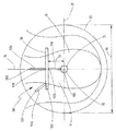
도 2는 프로펠러의 상류에 배치된, 아치 형상으로 구성된 흐름-안내 표면을 구비하는 헐의 하부 영역의 배면도를 도시한다.
도 3은 제1 핀을 구비하는 흐름-안내 표면의 측면도를 도시한다.
도 4는 아치형으로 구성된 흐름-안내 표면을 구비하는 추가적인 실시예의 사시도를 도시한다.
도 5는 핀의 단면도를 도시한다.
도 6은 프로펠러와 동축으로 배치된 포어(fore)-노즐을 구비하는 헐의 하부 영역의 배면도를 도시한다.
도 7은 프로펠러 축에 대하여 위로 옮겨진(shifted) 포어-노즐을 구비하는 헐의 하부 영역의 배면도를 도시한다.
도 8은 프로펠러 축에 대하여 경사진 외부 핀을 구비하는 포어-노즐의 측면도를 도시한다.
도 9는 디바이스의 추가적인 실시예의 사시도를 도시한다.
도 10은 도 9로부터 디바이스의 측면도를 도시한다.
도 11은 헐 상에 설치된 디바이스의 추가적인 실시예의 사시도를 도시한다.
다음과 같이 도시된 다양한 실시예들에서, 동일한 구성요소들에는 동일한 도면 부호들이 제공된다.BRIEF DESCRIPTION OF THE DRAWINGS The invention is described in more detail below by way of example embodiments illustrated in the drawings. In the drawings, it is schematically shown as follows.
Fig. 1 shows a rear view of the lower area of the hull with a flow-guiding surface arranged in the form of a plate, arranged upstream of the propeller.
Figure 2 shows a rear view of the lower region of the hull with a flow-guiding surface configured in an arch shape, disposed upstream of the propeller.
Figure 3 shows a side view of a flow-guiding surface with a first fin.
Figure 4 shows a perspective view of a further embodiment with an arcuately configured flow-guiding surface.
Figure 5 shows a cross-sectional view of the pin.
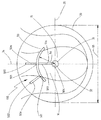
Figure 6 shows a rear view of the lower region of the hull with a fore-nozzle arranged coaxially with the propeller.
Figure 7 shows a rear view of the lower region of the hull with the pour-nozzle shifted up relative to the propeller shaft.
Figure 8 shows a side view of a pioneer nozzle with an external pin inclined relative to the propeller shaft.
Figure 9 shows a perspective view of a further embodiment of the device.
Figure 10 shows a side view of the device from Figure 9;
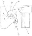
Fig. 11 shows a perspective view of a further embodiment of a device installed in a loose phase.
In the various embodiments shown below, the same components are provided with the same reference numerals.
도 1은 헐(hull; 30)의 후방 하부 영역의 배면도를 도시한다. 스턴 튜브(stern tube)로 구성된 샤프트 베어링(shaft bearing; 31)은 대략적으로 수평 방향으로 스턴에서 헐(30)로부터 돌출된다. 도 1의 다이어그램에서, 샤프트 베어링(31)은 도면의 평면으로부터 밖으로 또는 안으로 나아간다. 프로펠러 축(32)을 따라 나아가는 (여기에서 도시되지 않은) 프로펠러 샤프트는 샤프트 베어링(31) 내에 장착된다. 도 1로부터의 다이어그램에서 프로펠러 축(32)은 또한 도면의 평면으로부터 밖으로 또는 안으로 이끈다. 프로펠러(33)는 이동 방향으로 흐름-안내 표면(flow-guiding surface; 50)의 하류, 그리고 따라서 도면의 평면 외부에 놓이므로 오직 프로펠러 서클(propeller circle)로서 개략적으로 나타내진다. 본 선박은 소위 단일-프로펠러 선박이고, 따라서 오직 하나의 프로펠러(33)를 구비한다.Fig. 1 shows a rear view of the rear lower region of the
흐름-안내 표면(50)은 프로펠러(33)의 상류에 프로펠러로부터 이격되어 배치된다. 게다가, 흐름-안내 표면(50)은 플레이트-형상으로 되도록 구성되고 프로펠러 축(32)에 대해 평행하는 평면 상에서 연장한다. 도 1에 도시된 바와 같이, 흐름-안내 표면(50)은 프로펠러 축(32)으로부터 일정한 거리(54)에 위치된다.The flow-guiding
도 1에서 도시된 디바이스(100)는 흐름-안내 표면(50)으로부터 외측으로 돌출하는 두 개의 제1 핀들(50a)을 구비한다. 이러한 두 개의 제1 핀들(50a) 각각은 그것의 제1 단부(501)를 구비하여 흐름-안내 표면(50)에 연결된다. 제1 핀(50a)의 개별적인 제2 단부(502)는 자유-직립 단부(free-standing end)로 구성된다. 게다가, 도 1에 도시된 디바이스는 제2 핀(51a)을 구비한다. 제2 핀(51a)은 그것의 제1 단부(503)를 구비하여 흐름-안내 표면(50)에 연결된다. 그것의 제2 단부(504)를 구비하여 제2 핀(51a)은 샤프트 베어링(31)에 연결된다.The
도 2는 헐(30)의 후방 영역의 배면도를 도시한다. 도 2에 따른 디바이스는 흐름-안내 표면(50)이 아치형으로 구성된다는 점에서 도 1에 따른 디바이스와 다르다.2 shows a rear view of the rear region of the
도 3은 선박의 하부 스턴 구획의 측면도를 도시한다. 헐(30)의 스턴으로부터 대략적으로 수평으로 돌출되는 것은 (여기에서 도시되지 않은) 프로펠러 샤프트가 위치되는 스턴 튜브로 구성된 샤프트 베어링(31)이다. 프로펠러 샤프트는 프로펠러 축(32)을 따라 나아간다. 프로펠러(33)는 샤프트 베어링(31)의 단부에 제공된다. 게다가, 이동 방향으로 프로펠러(33)의 상류에서 흐름-안내 표면(50)은 프로펠러(33)로부터 이격되어 그리고 프로펠러(33)의 상류에 도시된다. 게다가, 외측으로 또는 상방으로 돌출되는 제1 핀(50a)은 흐름-안내 표면(50) 상에 위치된다. 제1 핀(50a)은 그것의 제1 단부(501)를 구비하여 상기 아치형으로 구성된 흐름-안내 표면(50)의 상부 영역 내에 흐름-안내 표면에 연결되는 반면 그것의 제2 단부(502)는 자유-직립 단부로 구성된다.Figure 3 shows a side view of the lower stern section of the ship. Projecting approximately horizontally from the stern of the
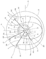
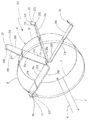
도 4는 추가적인 실시예에 따른 디바이스(100)의 사시도를 도시한다. 디바이스(100)는 또한 원주 방향으로 개방되도록 구성된 포어-노즐(10) 및 네 개의 외부 핀들(20a 내지 20d)뿐만 아니라 네 개의 내부 핀들(21a 내지 21d)을 포함하고, 이때 각각의 경우에 핀 쌍(fin pair; 20a, 21a; 20b, 21b; 20c, 21c; 20d, 21d)은 완전한 핀을 형성한다. 그러므로 도 4에 따라, 흐름-안내 표면(50)은 개방된 노즐 링(open nozzle ring)으로 구성된다. 개방된 노즐 링은 대략적으로 소위 2/3 노즐에 대응되는데, 노즐 링이 대략적으로 원주 방향으로 폐쇄된 노즐( circumferentially closed nozzle)의 2/3에 대응되기 때문이다. 게다가, 도 9에 대한 설명이 참조된다. 도 9는 유사한 실시예를 도시하나, 도 4에 도시된 실시예와 대조적으로, 도 9에서 디바이스(100)는 원주 방향으로 폐쇄되도록 구성된 포어-노즐(10)을 도시한다.Figure 4 shows a perspective view of a
도 5는 핀의 예시의 단면도를 도시한다. 도시된 핀은 이론적으로 제1 핀(50a) 또는 제2 핀(51a)의 단면으로 될 수 있다. 도 5에 도시된 예시에서, 도시된 핀은 제1 핀(50a)이다. 핀(50a)은 도 5의 도면에서 상부에 배치된 구부러진 석션 측(curved suction side; 203) 및 반대되게 배치된, 실질적으로 편평한 압력 측(flat pressure side; 204)을 구비한다. 핀(50a)의 리딩 가장자리의 일부를 형성하는 둥근 정면(rounded front face; 205)은 포어-노즐(10) 내에 설치된, 즉 상류에 배치된 상태로 흐름 내에 위치될 수 있다. 그러한 효과를 위해, 핀(50a)의 트레일링 가장자리의 일부를 형성하는 대략적으로 뾰족한 후면(pointed rear face; 206)은 포어-노즐(10) 내에 설치된 상태에서 프로펠러 흐름의 하류에 위치될 수 있다.Figure 5 shows a cross-sectional view of an example of a fin. The pin shown may theoretically be a cross section of the
도 6은 헐(30)의 후방 하부 영역의 배면도를 도시한다. 스턴 튜브로 구성된 샤프트 베어링(31)은 대략적으로 수평 방향으로 스턴에서(from the stern) 헐(30)로부터 돌출된다. 도 6의 다이어그램에서, 샤프트 베어링(31)은 도면의 평면으로부터 밖으로 또는 안으로 나아간다. 프로펠러 축(32)을 따라 나아가는 (여기에서 도시되지 않은) 프로펠러 샤프트는 샤프트 베어링(31) 내에 장착된다. 도 6으로부터의 다이어그램에서, 프로펠러 축(32)은 또한 도면의 평면으로부터 밖으로 또는 안으로 이끈다. 프로펠러 축(32)은 동시에 프로펠러 축(32)에 대해 동심으로 배치된 포어-노즐(10)의 길이방향 축을 형성한다. 본 예시적인 실시예에서 포어-노즐(10)은 회전 대칭 바디(rotationally symmetrical body)로 도시되었으므로, 프로펠러 축(32)은 동시에 또한 포어-노즐(10)의 회전축을 형성한다. 프로펠러(33)는 이동 방향으로 포어-노즐(10)의 하류에, 따라서 도면의 평면 외부에 놓이므로 오직 프로펠러 서클로 개략적으로 나타내진다. 본 선박은 소위 단일-프로펠러 선박이므로 오직 하나의 프로펠러(33)를 구비한다.Fig. 6 shows a rear view of the rear lower region of the
포어-노즐(10)은 내벽 표면(inner wall surface; 12) 및 외부 노즐 벽 표면(outer nozzle wall surface; 13)을 포함하는 원주방향으로 폐쇄된 노즐 벽(circumferentially closed nozzle wall; 11)을 구비한다. 수직 중심선(vertical central line; 34) 및 수평 중심선(horizontal central line; 35)은 프로펠러(33)를 관통하여 도시된다. 포어-노즐(10)은 프로펠러(33)에 대해 동심으로 배치되므로, 중심선들(34, 35)은 또한 포어-노즐(10)을 위한 중심선들이다. 프로펠러 축(32)은 두 개의 중심선들(34, 35)의 교차점에 놓인다. 수직 중심선(34)에 의한 포어-노즐(10)의 가상 분할에서, 좌측 포어-노즐 절반은 포어-노즐(10)의 프로펠러 상방-비팅 측(14)이고 우측 포어-노즐 절반은 포어-노즐(10)의 프로펠러 하방-비팅 측(15)이다.The pore-
샤프트 베어링(31) 및 포어-노즐 벽(11)의 내측(12) 사이에서 나아가도록 각각 배치된 내부 핀들(21a, 21b, 21c)은 (우측 프로펠러에 대하여) 포어-노즐(10)의 프로펠러 상방-비팅 측(14) 상에 제공된다. 또한 샤프트 베어링(31) 및 포어-노즐 벽(11) 사이에서 나아가는 다른 내부 핀들(21d)은 프로펠러 하방-비팅 측(15) 상에 그리고 구체적으로 수평 중심선(35) 상에 장착된다. 내부 핀들(21a, 21b, 21c, 21d)은 각각 샤프트 베어링(31) 상에 및 포어-노즐(10) 상에 고정된다. 외부 포어-노즐 벽 표면(13)으로부터, 네 개의 외부 핀들(20a, 20b, 20c, 20d)은 포어-노즐(10)로부터 외측으로 돌출된다. 외부 핀들(20a, 20b, 20c, 20d)은 내부 핀들(21a, 21b, 21c, 21d)의 연장부(extension) 내에 각각 배치된다. 외부 핀들(20a, 20b, 20c, 20d) 및 내부 핀들(21a, 21b, 21c, 21d)은 모두 포어-노즐의 회전축 또는 프로펠러 축(32)에 대해 방사상으로 배치되고 따라서 프로펠러 축(32)에 대해 방사상 방향으로 나아간다. 내부 핀들(21a, 21b, 21c, 21d)의 길이방향 축은 대략적으로 가상의 연장부 내에 외부 핀들(20a, 20b, 20c, 20d)의 길이방향 축에 대응한다. 그러므로 개별적인 핀 쌍들(20a, 21a; 20b, 21b; 20c, 21c; 20d, 21d)은 각각 완전한 핀을 형성한다. 즉, 그것들은 유체적으로 대략적으로 연속적인 핀으로 작용하나 사실상 포어-노즐(10)에 의해 간섭되고 각각 그 위에 (예를 들어, 용접에 의해 또는 포어-노즐에 용접에 의해) 고정된다. 이에 의해 디바이스(100)는 완전한 핀의 상대적으로 큰 길이를 구비하여 높은 안정성을 획득한다.The
전체에 걸쳐 세 개의 완전한 핀들은 프로펠러 상방-비팅 측(14) 상에 배치되고 하나의 완전한 핀은 프로펠러 하방-비팅 측(15) 상에 배치된다. 프로펠러 하방-비팅 측(15) 상에 그리고 구체적으로 수평 중심선(35) 아래에, 샤프트 베어링(31) 및 포어-노즐(10) 사이에서 나아가고 양쪽에 연결된 안정화 스트러트(stabilizing strut; 22)가 더 제공된다. 안정화 스트러트(22)는 압축 또는 인장 로드로 작용하고 헐에 포어-노즐(10)을 장착하여 이것을 안정화시키는 방식으로 구성된다. 안정화 스트러트(22)는 핀으로 구성되지 않고, 즉 하이드로포일 프로파일(hydrofoil profile) 등을 구비하지 않고 흐름에 가능한 한 작게 영향을 미치는 방식으로 구성된다. 안정화 스트러트(22)는 핀들(20a, 20b, 20c, 20d, 21a, 21b, 21c, 21d)에 비해 큰 프로파일 폭을 구비한다.All three complete pins are disposed on the propeller upper-beating
외부 핀들(20a, 20b, 20c, 20d )은 각각 포어-노즐(10)의 외벽 표면(13) 상에 배치되고 포어-노즐(10)에 연결된 제1 단부(201)를 구비한다. 외부 핀들은 또한 자유단으로 구성된 제1 단부(201)에 반대되는 제2 단부(202)를 구비한다. 핀 단부 피스들(fin end pieces; 23)은 제2 단부(202)로부터 측면으로 돌출된다. 도 6의 다이어그램에서, 핀 단부 피스들(23)은 각각 외부 핀들(20a, 20b, 20c)의 하측을 향해 각각 뾰족하게 되고, 석션 측을 형성한다. 외부 핀(20d)에서, 서로에 대해 대칭으로 배치된 핀 단부 피스들(23)은 자유단(202) 상에 제공된다. 하나의 핀 단부 피스(23)는 외부 핀(20d)의 하측을 향해 및 상측을 향해 돌출된다. 핀 단부 피스들(23)은 "윙릿들(winglets)"로 작용하고 소위 분리 난류(detachment turbulence) 및 외부 핀들(20a, 20b, 20c, 20d)의 자유단들(202)의 영역 내 캐비테이션의 발생을 감소시킨다. 핀 단부 피스들(23)은 각각 방사상으로 개별적인 외부 핀(20a, 20b, 20c, 20d) 안으로 나아간다.The
도 7은 도 6과 유사한 도면을 도시한다. 도 7에 따른 실시예에는, 도 6과 달리, 회전축(16)을 구비하고, 동시에 포어-노즐(10)의 길이방향 축을 형성하는 포어-노즐(10)이 프로펠러 축(32)에 대해 상방으로 옮겨진다. 따라서, 내부 핀들(21a, 21b, 21c, 21d)은 다른 길이들을 구비하는 반면, 도 6으로부터의 다이어그램에서 내부 핀들(21a, 21b, 21c, 21d)은 모두 동일한 길이를 구비한다. 안정화 스트러트(22)는 또한 도 6으로부터의 실시예에 비해 짧아진다. 도 7로부터의 다이어그램에서, 외부 핀들(20a, 20b, 20c, 20d)은 또한 다른 길이들을 구비하는 반면, 도 6으로부터의 다이어그램에서 각각 동일한 길이를 구비한다. 도 6으로부터의 실시예 및 도 7로부터의 실시예 모두에서, 프로펠러(33)의 반경은 각각의 경우에 (가장 긴) 완전한 핀의 길이보다 길다. 도 7로부터의 실시예에서 (예를 들어 외부 핀(20c) 및 내부 핀(21c)으로 구성된) 가장 긴 완전한 핀의 길이는 도 6에서의 완전한 핀보다 길다.Figure 7 shows a view similar to Figure 6. In the embodiment according to Fig. 7, unlike Fig. 6, a
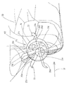
도 8은 선박의 하부 스턴 섹션의 측면도를 도시한다, (여기에서 도시되지 않은) 프로펠러 샤프트가 배치된 스턴 튜브로 구성된, 샤프트 베어링(31)은 헐(30)의 스턴으로부터 대략적으로 수평으로 돌출된다. 프로펠러 샤프트는 프로펠러 축(32)을 따라 나아간다. 프로펠러(33)는 샤프트 베어링(31)의 단부에 제공된다. 포어-노즐(10)은 이동 방향으로 프로펠러(33)의 앞에 더 제공된다. 회전축 또는 길이방향 축(16)은 회전 대칭 포어-노즐(10)을 통해 중심으로 나아간다. 포어-노즐(10)은 프로펠러 축(32)에 대해 회전축(16)을 구비하여 상방으로 옮겨진다. 게다가, 회전축(16)은 프로펠러 축(32)에 대해 각도(α)로 경사진다. 즉, 포어-노즐(10)은 이동 방향으로 보일 때, 프로펠러 축(32)에 대해 전방으로 및 하방으로 경사지거나 기울어진, 그것의 리딩 상부 가장자리 영역(leading upper edge region)을 구비하여 정렬되거나 배치된다. 포어-노즐(10)의 상부 영역에서, 외부 핀(20)은 포어-노즐(10)로부터 상방으로 돌출된다. 외부 핀(20)은 이동 방향으로 보일 때 프로펠러(33)를 향하는 포어-노즐(10)의 트레일링 영역 내에 위치된다. 선박을 조종하기 위한 러더(rudder; 36)는 이동 방향으로 프로펠러(33)의 하류에 제공된다. Figure 8 shows a side view of the lower stern section of the vessel. The
도 9는 본 발명에 따른 다른 실시예의 디바이스(100)의 사시도를 도시한다. 이 디바이스(100)는 또한 원주 방향으로 그것 자체 안으로 폐쇄된 노즐 링 또는 포어-노즐(10) 및 네 개의 외부 핀들(20a 내지 20d) 및 네 개의 내부 핀들(21a 내지 21d)을 포함하고, 이때 개별적으로 한 쌍의 핀들(20a, 21a; 20b, 21b; 20c, 21c; 20d, 21d)은 완전한 핀을 형성한다. 개별적인 핀들(20a 내지 20d; 21a 내지 21d)은 각각 도 5에 도시된 바와 같은 방식으로 단면 프로파일(cross-sectional profile)을 구비한다. 특히, 각각의 핀들(20a 내지 20d; 21a 내지 21d)은 석션 측(203) 및 압력 측(204)을 포함한다. 핀들(20a 내지 20d; 21a 내지 21d)은 포어-노즐(10)의 후방 영역 내에 각각 배치된다. 도 9의 다이어그램은 분해된 도면을 도시하여 개별적인 핀들(20a 내지 20d; 21a 내지 21d)은 연속적으로 포어-노즐(10)에 연결된 상태로 도시되지 않는다. 외부 핀들(20a 내지 20d) 및 내부 핀들(21a 내지 21d)은 모두 이동 방향(30)으로 보일 때 포어-노즐(10)의 후방 영역 내에 배치된다. 특히, 후방 영역은 이동 방향으로 보일 때 포어-노즐(10)의 총 길이의 70%, 바람직하게 55%보다 길지 않다. 포어-노즐(10)은 도 9에서 투명하게 도시되며 명확화를 위해 외부 핀들(20a 내지 20d) 및 내부 핀들(21a 내지 21d)은 각각 완전히 동일할 수 있다.Figure 9 shows a perspective view of a
외부 핀들(20a 내지 20d)의 제2 단부들(202) 각각에 부착된 핀 단부 피스들(23)은 플레이트들의 방식으로 구성되고 외부 핀들(20a 내지 20d)로부터 일 측 상에서 측면으로 돌출된다. 외부 핀들(20a-20d)의 정면(205) 또는 리딩 가장자리를 향하여, 플레이트들로 구성된 핀 단부 피스들(23)의 가장자리(231)는 약간 비스듬하게 후방으로 및 포어-노즐(10)의 주된 유입 방향(18)에 측면으로 나아간다. 핀 단부 피스들(23)의 두 개의 측면 가장자리들(232)은 주된 유입 방향(18)에 대해 대략적으로 평행하게 정렬되는 반면 핀 단부 피스들(23)의 트레일링 가장자리(233)는 주된 유입 방향(18)에 실질적으로 직교하게 나아간다. 외부 핀들(20a to 20d)의 길이방향에 대하여, 핀 단부 피스들(23)은 90˚ 내지 120˚의 각도로 외측으로 돌출되고, 이때 우측 프로펠러(right-handed propeller)의 경우에 프로펠러의 회전 방향으로 외부 핀들(20a 내지 20d)로부터 측면으로 돌출된다. 도 9로부터의 디바이스(100)에서, 내부 핀들(21a 내지 21d)은 각각 외부 핀들(20a 내지 20d)보다 큰 길이를 구비한다. 게다가 모든 외부 핀들(20a 내지 20d)은 그것들의 길이, 폭 및 깊이, 그리고 프로파일 형상에 대하여 동일한 치수들을 구비한다. 그것은 내부 핀들(21a 내지 21d)에 대하여 유사하게 적용된다. 내부 핀들(21a 내지 21d)은 동일한 길이를 구비하므로, 포어-노즐(10)의 회전축 또는 길이방향 축은 프로펠러 축과 동축으로 배치되고, 즉 두 개의 축들은 다른 것 위에 하나가 놓인다.The
외부 핀들(20a 내지 20d)은 스윕되도록(swept) 구성되는 반면 내부 핀들(21a 내지 21d)은 비-스윕되도록(non-swept) 구성된다. 이는 측면도로 도 9로부터의 디바이스(100)를 도시하는 도 10에서 상세히 보일 수 있다. 포어-노즐(10)의 회전축 또는 길이방향 축(16)은 도 10의 다이어그램에서 나타내진다. 회전축(16)에 대한 제1 상방-돌출 직교선(first upwardly-projecting orthogonal; 17a) 및 제2 하방-돌출 직교선(second downwardly-projecting orthogonal; 17b)은 나타내진다. 포어-노즐(10)은 도 10에서 투명하게 도시되며 명확화를 위해 안에 있는 내부 핀들(21b 내지 21d)은 동일하게 될 수 있다. 내부 핀(21b)의 리딩 가장자리(205)가 직교선(17a)에 대하여 실질적으로 평행하게 배치되는 것이 더 확인될 수 있다. 또한 내부 핀(21d)의 트레일링 가장자리(206)가 직교선(17b)에 대하여 실질적으로 평행하게 배치되는 것이 확인될 수 있다. 내부 핀들(21b 내지 21d)은 동일한 구성을 구비하므로, 이러한 평행하는 배치들은 모든 내부 핀들(21b 내지 21d)에 대하여 유사하게 적용된다. 다시 말해서, 내부 핀들(21b 내지 21d)의 깊이는 주된 유입 방향(18)으로 보일 때 또는 이동 방향(37)으로 보일 때 실질적으로 내부 핀들(21b 내지 21d)의 길이 상에서 일정하다. 따라서 내부 핀들(21b)은 비-스윕되도록 구성된다.The
이와 대조적으로, 외부 핀들(20b 내지 20d)은 스윕되도록 구성되고 구체적으로 리딩-가장자리 스윕(leading-edge sweep)을 구비한다. 따라서, 외부 핀(20b)의 리딩 가장자리(205)는 직교선(17a)에 대하여 스윕 각도(sweep angle; β)에서 정렬된다. 이는 동일한 구성의 결과로서 남아있는 외부 핀들에 대하여 유사하게 적용된다. 외부 핀들(20b 내지 20d)의 트레일링 가장자리들(206)은 직교선들(17a, 17b)에 대하여 실질적으로 평행하게 정렬되어 외부 핀들(20b 내지 20d)의 트레일링 가장자리가 스윕되지 않으며, 즉 직교선들에 대하여 각이 지게 경사지지 않는다. 따라서 제1 단부(201)로부터 제2 단부(202)로 이동 방향(37)으로 보일 때 외부 핀들(20b 내지 20d)의 깊이가 감소된다. 리딩 가장자리(205)는 직선이므로(rectilinear), 일단(201)으로부터 타단(202)으로의 감소는 연속적이다. 도 10에 도시되지 않은 외부 핀(20a) 및 내부 핀(21a)은 다른 외부 핀들(20b 내지 20d) 및 내부 핀들(21b 내지 21d)에 대해 유사하게 구성된다.In contrast, the
포어-노즐(10)의 외부 직경이 주된 유입 방향(18)에서 연속적으로 감소하는 것이 도 10에서 더 확인될 수 있다. 이와 마찬가지로, 포어-노즐(10)의 내부 직경은 주된 유입 방향(18)으로 감소하나 프로파일 도면(profile view)에서 내부 포어-노즐 벽 표면(11)의 아치형 구성의 결과로서 연속적이지 않다.It can further be seen in FIG. 10 that the outer diameter of the pore-
도 11은 도 9 및 10과 유사하게 구성된 본 발명에 따른 디바이스(100)의 다른 실시예를 도시한다. 특히 디바이스(100)는 또한 네 개의 외부 핀들(20a 내지 20d) 및 네 개의 내부 핀들(21a 내지 21d)을 포함하고 이때 개별적으로 하나의 핀 쌍은 완전한 핀을 형성한다. 도 11로부터의 실시예에서 그리고 도 9 및 10, 및 1 및 2로부터의 실시예에서, 완전한 핀들은 포어-노즐(10) 내부에 비대칭으로 배치된다.Figure 11 shows another embodiment of a
도 9 및 10에 따른 실시예와 대조적으로, 도 11로부터의 실시예에서, 외부 핀들(20a 내지 20d)의 제2 단부(203)는 핀 단부 피스들(23) 안으로 각이 지게 나아가지 않고, 반경(radius)을 구비하는 트랜지션(transition; 23a)을 구비하여 나아간다. 게다가, 도 11에서 완전한 핀들은 포어-노즐들(10)을 통해 나아가고, 즉, 완전한 핀들은 하나의 피스로 형성되는 반면, 도 9 및 10으로부터의 실시예에서 완전한 핀들은 두 개의 피스들로 각각 형성되며 내부 핀들 및 외부 핀들은 각각 포어-노즐(10)에 개별적으로 장착된다. 도 9 및 10에 따른 실시예에 대하여 도 11에 따른 실시예에서의 다른 차이점은 내부 핀들(21a 내지 21d) 및 외부 핀들(20a 내지 20d) 모두 스윕되도록 구성된다는 것을 포함한다. 여기서 또한 핀의 리딩 가장자리만이 각각의 경우에 스윕되도록 구성되고, 트레일링 가장자리는 그렇지 않다. 내부 핀들(21a 내지 21d)의 리딩 가장자리들의 스윕은 외부 핀들(20a 내지 20d)에 대해서와 같이 회전축에 대한 직교선에 대해 동일한 각도로 달성되어 동일한 각도를 구비하는 연속적인 리딩-가장자리 스윕이 획득된다.In contrast to the embodiment according to Figs. 9 and 10, in the embodiment from Fig. 11, the
디바이스(100)가 헐(30) 상에 구체적으로 이동 방향(37)으로 헐(30)의 후방 단부에 장착되는 것이 도 11에서 더 확인될 수 있다.It can further be seen in FIG. 11 that the
100: 디바이스
10: 포어-노즐
11: 포어-노즐 벽
12: 내부 포어-노즐 벽 표면
13: 외부 포어-노즐 벽 표면
14: 프로펠러 상방-비팅 측
15: 프로펠러 하방-비팅 측
16: 포어-노즐의 회전축
17: 회전축에 대한 직교선
18: 주된 유입 방향
20, 20a, 20b, 20c, 20d: 외부 핀들
201: 외부 핀의 제1 단부
202: 외부 핀의 제2 단부
203: 석션 측
204: 압력 측
205: 정면
206: 후면
21a, 21b, 21c, 21d: 내부 핀들
22: 안정화 스트러트
23: 핀 단부 피스
23a: 트랜지션
30: 선박의 헐
31: 샤프트 베어링
32: 프로펠러 축
33: 프로렐러
34: 수직 중심선
35: 수평 중심선
36: 러더
37: 이동 방향
50: 흐름-안내 표면
50a: 제1 핀
51: 흐름-안내 표면의 프로파일 두께
51a: 제2 핀
52: 프로파일 입구 가장자리
53: 프로파일 출구 가장자리
54: 흐름-안내 표면 및 프로펠러 축 사이의 거리
55: 프로펠러 직경
501: 제1 핀의 제1 단부
502: 제1 핀의 제2 단부
503: 제2 핀의 제1 단부
504: 제2 핀의 제2 단부
α: 회전축 및 프로펠러 축 사이의 교차 각도
β: 스윕 각도100: device
10: pore-nozzle
11: Pore-nozzle wall
12: Internal pore-nozzle wall surface
13: External pore-nozzle wall surface
14: Upper propeller - Beating side
15: Down side of propeller - Beating side
16: Pore - the rotational axis of the nozzle
17: orthogonal line to the rotation axis
18: Main inlet direction
20, 20a, 20b, 20c, 20d: external pins
201: first end of outer pin
202: second end of outer pin
203: Suction side
204: Pressure side
205: Front
206: rear
21a, 21b, 21c, 21d:
22: stabilization strut
23: pin end piece
23a: Transition
30: Hull of the ship
31: Shaft bearing
32: Propeller shaft
33:
34: vertical center line
35: horizontal center line
36: Rudder
37: Direction of movement
50: Flow-guiding surface
50a: first pin
51: Profile thickness of the flow-guiding surface
51a: second pin
52: profile entrance edge
53: Profile exit edge
54: Flow-distance between guiding surface and propeller shaft
55: Propeller diameter
501: first end of first pin
502: second end of first pin
503: first end of the second pin
504: second end of second pin
α: Angle of intersection between the rotating shaft and the propeller shaft
β: sweep angle
Claims (26)
상기 디바이스는 흐름-안내 표면(50)을 포함하고,
적어도 하나의 제1 핀(50a)이 상기 흐름-안내 표면(50)으로부터 돌출되며,
상기 제1 핀(50a)의 제1 단부(201, 501)가 상기 흐름-안내 표면(50)에 장착되고 상기 제1 핀(50a)의 제2 단부(502)가 자유단으로 구성되는 것을 특징으로 하는 디바이스.
CLAIMS 1. A device (100) for reducing the power output requirements of a watercraft, in particular a ship,
The device includes a flow-guiding surface (50)
At least one first pin (50a) projects from the flow-guiding surface (50)
Characterized in that the first end (201, 501) of the first fin (50a) is mounted on the flow-guiding surface (50) and the second end (502) of the first fin Lt; / RTI >
흐름-안내 표면(50)은 프로펠러(33)의 상류에 배치되고, 흐름-안내 표면(50)은 프로펠러(33)로부터 이격되어 배치되며, 흐름-안내 표면(50)은 워터크래프트의 프로펠러(33)의 프로펠러 샤프트를 장착하도록 구성된, 샤프트 베어링(31), 특히 스턴(stern) 튜브로부터 이격되어 배치되는 것을 특징으로 하는 디바이스.
The method according to claim 1,
The flow-guiding surface 50 is disposed upstream of the propeller 33 and the flow-guiding surface 50 is disposed away from the propeller 33 and the flow- (31), in particular a stern tube, adapted to mount a propeller shaft of a propeller shaft.
제1 핀(50a)의 제1 단부(501) 및 프로펠러 축(32) 사이의 거리는 제1 핀(50a)의 제2 단부(502) 및 프로펠러 축(32) 사이의 거리보다 짧은 것을 특징으로 하는 디바이스.
3. The method according to claim 1 or 2,
The distance between the first end 501 of the first pin 50a and the propeller shaft 32 is less than the distance between the second end 502 of the first pin 50a and the propeller shaft 32 device.
상기 제1 핀(50a)은 가장 큰 프로파일 두께(51)를 구비하고, 제1 핀(50a)의 가장 큰 프로파일 두께(51)는 제1 핀(50a)의 제2 단부(502) 및 제1 단부(501) 사이의 거리의 50%보다 작은, 바람직하게 25%보다 작은, 특히 바람직하게 15%보다 작은 것을 특징으로 하는 디바이스.
4. The method according to any one of claims 1 to 3,
The first pin 50a has the largest profile thickness 51 and the largest profile thickness 51 of the first pin 50a is greater than the second profile 50 of the first pin 50a, Is less than 50%, preferably less than 25%, particularly preferably less than 15% of the distance between the ends (501).
흐름-안내 표면(50)은 프로펠러(33)로부터 멀리 향해진 전방-측 프로파일 입구 가장자리(52)를 구비하고, 흐름-안내 표면(50)은 프로펠러(33)를 향해 향해진 전방-측 프로파일 출구 가장자리(53)를 구비하고, 프로파일 입구 가장자리(52) 영역 내 프로펠러 축(32) 및 흐름-안내 표면(50) 사이의 거리는 프로파일 출구 가장자리(53)의 영역 내 프로펠러 축(32) 및 흐름-안내 표면(50) 사이의 거리보다 작거나 큰 것을 특징으로 하는 디바이스.
5. The method according to any one of claims 1 to 4,
The flow-guiding surface 50 has a front-side profile inlet edge 52 that is directed away from the propeller 33 and the flow-guiding surface 50 has a front-side profile outlet 52 directed towards the propeller 33, And the distance between the propeller shaft 32 and the flow-guiding surface 50 in the region of the profile inlet edge 52 is greater than the distance between the propeller shaft 32 and the flow- Is less than or greater than the distance between surfaces (50).
흐름-안내 표면(50) 및 프로펠러 축(32) 사이의 최단 거리(54)는 프로펠러 직경(55)의 절반보다 작은 것을 특징으로 하는 디바이스.
6. The method according to any one of claims 1 to 5,
Wherein the shortest distance (54) between the flow-guiding surface (50) and the propeller shaft (32) is less than half of the propeller diameter (55).
적어도 하나의 제2 핀(51a)은 흐름-안내 표면(50)으로부터 돌출되고, 제2 핀(51a)의 제1 단부(503)는 흐름-안내 표면(50) 상에 배치되고, 제2 핀(51a)의 제2 단부(504)는 헐 상에 및/또는 샤프트 베어링(31), 특히 워터크래프트의 프로펠러(33)의 프로펠러 샤프트를 장착하도록 구성된 스턴 튜브 상에 장착되는 것을 특징으로 하는 디바이스.
7. The method according to any one of claims 1 to 6,
At least one second pin 51a projects from the flow-guiding surface 50 and a first end 503 of the second pin 51a is disposed on the flow-guiding surface 50, Characterized in that the second end (504) of the shaft (51a) is mounted on the hull and / or on a stern tube configured to mount a propeller shaft of a shaft bearing (31), in particular a watercraft propeller (33).
제1 핀(50a) 및/또는 제2 핀(51a)은 워터크래프트의 프로펠러(33)의 프로펠러 축(32)에 방사상으로 배치되는 것을 특징으로 하는 디바이스.
8. The method according to any one of claims 1 to 7,
Characterized in that the first pin (50a) and / or the second pin (51a) are arranged radially on the propeller shaft (32) of the propeller (33) of the watercraft.
제1 핀(50a)은 제2 핀(51a)의 연장부(extension)에 배치되고 제1 핀 및 상기 제2 핀은 함께 완전한 핀을 형성하는 것을 특징으로 하는 디바이스.
9. The method according to claim 7 or 8,
Wherein the first pin (50a) is disposed at an extension of the second pin (51a) and the first pin and the second pin together form a complete pin.
완전한 핀의 길이는 워터크래프트의 프로펠러(33)의 반경보다 작거나 크고, 바람직하게 완전한 핀의 길이는 프로펠러(33)의 반경의 최대 90%이고, 특히 바람직하게 완전한 핀의 길이는 프로펠러(33)의 반경의 최대 75%인 것을 특징으로 하는 디바이스.
10. The method of claim 9,
The length of the complete pin is preferably less than or greater than the radius of the propeller 33 of the watercraft and preferably the length of the complete pin is at most 90% of the radius of the propeller 33, RTI ID = 0.0 > 75%. ≪ / RTI >
제1 핀(50a) 및/또는 제2 핀(51a)은 프로펠러 축(32)에 대해 어택각에 배치되고, 특히 제1 핀(50a) 및 제2 핀(51a)은 다른 어택각들을 구비하는 것을 특징으로 하는 디바이스.
11. The method according to any one of claims 1 to 10,
The first pin 50a and / or the second pin 51a are disposed at an attack angle with respect to the propeller shaft 32 and in particular the first pin 50a and the second pin 51a have different attack angles ≪ / RTI >
제1 핀(50a)은 제1 핀(50a)으로부터 돌출된 핀 단부 피스(23)가 제공되는 자유단(502)을 구비하는 것을 특징으로 하는 디바이스.
12. The method according to any one of claims 1 to 11,
Characterized in that the first pin (50a) has a free end (502) provided with a pin end piece (23) projecting from the first pin (50a).
핀 단부 피스(23)는 제1 핀(50a)의 자유단 안으로 방사상으로(at a radius) 또는 각이 지게 나아가는 것을 특징으로 하는 디바이스.
13. The method of claim 12,
Characterized in that the pin end piece (23) is radially (at a radius) or angled into the free end of the first fin (50a).
핀 단부 피스(23)는 오직 제1 핀(50a)으로부터 제1 핀(50a)의 양측들 또는 일측 상에서 돌출되고, 일-측 형성(one-sided formation)의 경우 제1 단부 피스(23)는 바람직하게 적어도 하나의 제1 핀(50a)의 석션 측(203)을 향해 돌출되는 것을 특징으로 하는 디바이스.
The method according to claim 12 or 13,
The pin end piece 23 protrudes only on either side or one side of the first fin 50a from the first fin 50a and the first end piece 23 in the case of one- Preferably toward the suction side (203) of the at least one first pin (50a).
다수의 핀들(20a, 20b, 20c, 20d, 50a, 21a, 21b, 21c, 21d, 51a)이 제공되고, 특히 프로펠러 하방-비팅 측(15) 상에서 보다 프로펠러 상방-비팅 측(14) 상에서 더 많은 핀들(20a, 20b, 20c, 20d, 50a, 21a, 21b, 21c, 21d, 51a)이 제공되고 및/또는 핀들(20a, 20b, 20c, 20d, 50a, 21a, 21b, 21c, 21d, 51a)이 비대칭 핀 시스템을 형성하는 방식으로 배치되는 것을 특징으로 하는 디바이스.
15. The method according to any one of claims 1 to 14,
A plurality of pins 20a, 20b, 20c, 20d, 50a, 21a, 21b, 21c, 21d, 51a are provided, and more particularly on the propeller upper-beating side 14 than on the propeller lower- The pins 20a, 20b, 20c, 20d, 50a, 21a, 21b, 21c, 21d, 51a are provided with the pins 20a, 20b, 20c, 20d, 50a, 21a, 21b, Are arranged in such a way as to form the asymmetric pin system.
제1 핀(50a)은 제2 핀(51a)보다 큰 길이를 구비하고, 바람직하게 제1 핀(50a)의 길이는 적어도 제2 핀(51a)의 길이의 1과 1/2배, 특히 바람직하게 제1 핀(50a)의 길이는 적어도 제2 핀(51a)의 길이의 2배인 것을 특징으로 하는 디바이스.
16. The method according to any one of claims 7 to 15,
The first pin 50a has a length greater than the second pin 51a and preferably the length of the first pin 50a is at least 1 and 1/2 times the length of the second pin 51a, Wherein the length of the first pin (50a) is at least twice the length of the second pin (51a).
흐름-안내 표면(50)의 가장 큰 프로파일 두께는 흐름-안내 표면(50)의 길이의 10%보다 작은, 바람직하게 7.5%보다 작은, 특히 바람직하게 6%보다 작은 것을 특징으로 하는 디바이스.
17. The method according to any one of claims 1 to 16,
Characterized in that the largest profile thickness of the flow-guiding surface (50) is less than 10%, preferably less than 7.5%, particularly preferably less than 6% of the length of the flow-guiding surface (50).
흐름-안내 표면(50) 및 프로펠러 축(32) 사이에 적어도 하나의 안정화 스트러트(22)가 흐름-안내 표면(50)을 안정화시키기 위해 제공되고, 안정화 스트러트(22)는 일단이 흐름-안내 표면(50) 상에 장착되고 타단이 워터크래프트의 프로펠러(33)의 프로펠러 샤프트를 장착하도록 구성된, 샤프트 베어링(31), 특히 스턴 튜브 상에 장착되며, 안정화 스트러트(22)는 핀 프로파일을 구비하거나 구비하지 않고 구성될 수 있는 것을 특징으로 하는 디바이스.
18. The method according to any one of claims 1 to 17,
At least one stabilizing strut 22 is provided between the flow-guiding surface 50 and the propeller shaft 32 to stabilize the flow-guiding surface 50 and the stabilizing strut 22 has one end connected to the flow- Is mounted on a shaft bearing (31), in particular a stern tube, which is mounted on a shaft (50) and the other end is adapted to mount a propeller shaft of a propeller (33) of a watercraft, the stabilizing strut (22) Lt; RTI ID = 0.0 > 1, < / RTI >
제1 핀(50a) 및/또는 제2 핀(51a)은 스윕되도록(swept) 구성되는 것을 특징으로 하는 디바이스.
19. The method according to any one of claims 1 to 18,
Wherein the first pin (50a) and / or the second pin (51a) are configured to sweep.
제9항을 다시 인용하여, 완전한 핀은 전체에 걸쳐(throughout) 스윕되도록 구성되는 것을 특징으로 하는 디바이스.
20. The method of claim 19,
Referring back to claim 9, the device is configured such that the complete pin is swept throughout.
흐름-안내 표면(50)은 원주 방향으로(circumferentially) 개방 또는 폐쇄되도록 구성되는 것을 특징으로 하는 디바이스.
21. The method according to any one of claims 1 to 20,
Wherein the flow-guiding surface (50) is configured to open or close circumferentially.
흐름-안내 표면(50)은 특히 곧은 평면 내에서, 곧도록 구성되는 것을 특징으로 하는 디바이스.
22. The method according to any one of claims 1 to 21,
Wherein the flow-guiding surface (50) is configured to be straight, in particular in a straight plane.
흐름-안내 표면(50)은 특히 프로펠러 축(32)에 대하여 볼록한, 아치형으로 구성되는 것을 특징으로 하는 디바이스.
23. The method according to any one of claims 1 to 22,
Characterized in that the flow-guiding surface (50) is in particular convex, arcuate with respect to the propeller shaft (32).
흐름-안내 표면(50)은 아치형으로 되고 원주 방향으로 개방되도록 구성되고, 흐름-안내 표면(50)의 호 길이는 단면으로 고려할 때 개념상으로 원주로 폐쇄된 흐름-안내 표면(50)의 원주의 80%보다 작은, 바람직하게 60%보다 작은, 특히 바람직하게 40%보다 작은, 더 특히 바람직하게 30%보다 작은 것을 특징으로 하는 디바이스.
24. The method according to any one of claims 1 to 23,
The flow-guiding surface 50 is configured to be arcuate and open in the circumferential direction, and the arc length of the flow-guiding surface 50, when considered in cross-section, is substantially equal to the circumference of the circumferentially closed flow- Is less than 80%, preferably less than 60%, particularly preferably less than 40%, more preferably less than 30%.
흐름-안내 표면(50)은 노즐, 바람직하게 포어-노즐(10)로부터 구성되는 것을 특징으로 하는 디바이스.
25. The method according to any one of claims 1 to 24,
Characterized in that the flow-guiding surface (50) consists of a nozzle, preferably a pore-nozzle (10).
포어-노즐(10)의 직경은 워터크래프트의 프로펠러(33) 직경의 70%보다 작은, 바람직하게 50%보다 작은, 특히 바람직하게 35%보다 작은 것을 특징으로 하는 디바이스.26. The method of claim 25,
The diameter of the pore-nozzle 10 is less than 70%, preferably less than 50%, particularly preferably less than 35% of the diameter of the propeller 33 of the watercraft.
Priority Applications (1)
| Application Number | Priority Date | Filing Date | Title |
|---|---|---|---|
| KR1020217002742A KR102412435B1 (en) | 2013-05-06 | 2014-03-31 | Device for reducing the driving power requirement of a watercraft |
Applications Claiming Priority (3)
| Application Number | Priority Date | Filing Date | Title |
|---|---|---|---|
| DE202013101943.7 | 2013-05-06 | ||
| DE202013101943U DE202013101943U1 (en) | 2013-05-06 | 2013-05-06 | Device for reducing the power requirement of a watercraft |
| PCT/EP2014/056412 WO2014180605A1 (en) | 2013-05-06 | 2014-03-31 | Device for reducing the driving power requirement of a watercraft |
Related Child Applications (1)
| Application Number | Title | Priority Date | Filing Date |
|---|---|---|---|
| KR1020217002742A Division KR102412435B1 (en) | 2013-05-06 | 2014-03-31 | Device for reducing the driving power requirement of a watercraft |
Publications (1)
| Publication Number | Publication Date |
|---|---|
| KR20160031452A true KR20160031452A (en) | 2016-03-22 |
Family
ID=48784199
Family Applications (3)
| Application Number | Title | Priority Date | Filing Date |
|---|---|---|---|
| KR1020157034659A KR20160031452A (en) | 2013-05-06 | 2014-03-31 | Device for reducing the driving power requirement of a watercraft |
| KR1020227020830A KR102512176B1 (en) | 2013-05-06 | 2014-03-31 | Device for reducing the driving power requirement of a watercraft |
| KR1020217002742A KR102412435B1 (en) | 2013-05-06 | 2014-03-31 | Device for reducing the driving power requirement of a watercraft |
Family Applications After (2)
| Application Number | Title | Priority Date | Filing Date |
|---|---|---|---|
| KR1020227020830A KR102512176B1 (en) | 2013-05-06 | 2014-03-31 | Device for reducing the driving power requirement of a watercraft |
| KR1020217002742A KR102412435B1 (en) | 2013-05-06 | 2014-03-31 | Device for reducing the driving power requirement of a watercraft |
Country Status (16)
| Country | Link |
|---|---|
| US (1) | US10005530B2 (en) |
| EP (1) | EP2994379B1 (en) |
| JP (1) | JP6678575B2 (en) |
| KR (3) | KR20160031452A (en) |
| CN (2) | CN203958582U (en) |
| CA (1) | CA2911459C (en) |
| DE (1) | DE202013101943U1 (en) |
| DK (1) | DK2994379T3 (en) |
| ES (1) | ES2737453T3 (en) |
| HK (1) | HK1219080A1 (en) |
| HR (1) | HRP20190973T1 (en) |
| PL (1) | PL2994379T3 (en) |
| SG (1) | SG11201509192TA (en) |
| TR (1) | TR201908084T4 (en) |
| TW (1) | TWI637881B (en) |
| WO (1) | WO2014180605A1 (en) |
Families Citing this family (9)
| Publication number | Priority date | Publication date | Assignee | Title |
|---|---|---|---|---|
| DE202013101943U1 (en) * | 2013-05-06 | 2013-06-11 | Becker Marine Systems Gmbh & Co. Kg | Device for reducing the power requirement of a watercraft |
| DE102015103285A1 (en) * | 2015-03-06 | 2016-09-08 | Becker Marine Systems Gmbh & Co. Kg | Arrangement for multi-propeller ships with external propeller shafts and method for producing such an arrangement |
| CN104828226A (en) * | 2015-04-21 | 2015-08-12 | 中国船舶工业集团公司第七〇八研究所 | Auxiliary propulsion energy-saving device for ship hydrodynamics |
| JP6239711B1 (en) * | 2016-09-15 | 2017-11-29 | サノヤス造船株式会社 | Ship duct equipment |
| SE544385C2 (en) * | 2019-09-23 | 2022-05-03 | Volvo Penta Corp | Propeller combination for a marine vessel |
| CN116348374A (en) * | 2020-05-28 | 2023-06-27 | 贝克船舶系统有限公司 | Device for reducing the propulsion power demand of a ship |
| CN114379752B (en) * | 2021-12-09 | 2022-08-26 | 南通海国机械有限公司 | Leading guide pulley of prewhirling for boats and ships |
| FI20225121A1 (en) * | 2022-02-11 | 2023-08-12 | Kongsberg Maritime Finland Oy | A flow guide arrangement of a rectracable thruster, a rectracable thruster, and a system |
| WO2024025376A1 (en) * | 2022-07-27 | 2024-02-01 | 에이치디한국조선해양 주식회사 | Ship structure |
Family Cites Families (23)
| Publication number | Priority date | Publication date | Assignee | Title |
|---|---|---|---|---|
| JPS5332594A (en) * | 1976-09-07 | 1978-03-27 | Hitachi Zosen Corp | Ship |
| JPS595680Y2 (en) * | 1980-07-22 | 1984-02-20 | 三菱重工業株式会社 | Ship propulsion performance improvement device |
| JPS60139699U (en) * | 1984-02-29 | 1985-09-14 | 三菱重工業株式会社 | Marine nozzle device |
| US5292088A (en) * | 1989-10-10 | 1994-03-08 | Lemont Harold E | Propulsive thrust ring system |
| US5634613A (en) * | 1994-07-18 | 1997-06-03 | Mccarthy; Peter T. | Tip vortex generation technology for creating a lift enhancing and drag reducing upwash effect |
| US5906522A (en) * | 1998-04-01 | 1999-05-25 | Hooper; Robert P. | Thrust enhancer for marine propeller |
| KR100394464B1 (en) * | 2000-12-01 | 2003-08-09 | 현대중공업 주식회사 | Y-shaped stator |
| US7267589B2 (en) * | 2004-07-22 | 2007-09-11 | Enviroprop Corporation | System and apparatus for improving safety and thrust from a hydro-drive device |
| KR100625847B1 (en) * | 2004-10-14 | 2006-09-20 | 부산대학교 산학협력단 | Asymmetric Pre-swirl Stator for Cavitation Suppression |
| KR100640299B1 (en) * | 2005-04-14 | 2006-10-30 | 대우조선해양 주식회사 | Installation structure for preswirl stator of ship |
| JP4717857B2 (en) * | 2007-06-14 | 2011-07-06 | 住友重機械マリンエンジニアリング株式会社 | Ship duct and ship |
| DE202008006069U1 (en) * | 2008-03-10 | 2008-07-17 | Becker Marine Systems Gmbh & Co. Kg | Device for reducing the power requirement of a ship |
| TW201010908A (en) * | 2008-09-02 | 2010-03-16 | Jen-Chen Tuan | Easily operable aircraft |
| JP2010195153A (en) * | 2009-02-24 | 2010-09-09 | Mitsubishi Heavy Ind Ltd | Reaction fin device for ship and ship |
| KR101023052B1 (en) | 2009-09-17 | 2011-03-24 | 대우조선해양 주식회사 | Ducted pre-swirl stator |
| KR20120068250A (en) * | 2010-12-17 | 2012-06-27 | 현대중공업 주식회사 | Duct structure for ship |
| DE202011000439U1 (en) * | 2011-02-25 | 2012-08-21 | Becker Marine Systems Gmbh & Co. Kg | Pre-nozzle for a propulsion system of a watercraft to improve energy efficiency |
| KR101334217B1 (en) * | 2011-05-03 | 2013-11-29 | 에스피피조선 주식회사 | Fuel-efficiecy Improving crown duct for ship |
| KR101723240B1 (en) * | 2011-05-13 | 2017-04-18 | 현대중공업 주식회사 | Propeller Duct Structure of Ship with Multi-Column Fin |
| CN202244050U (en) | 2011-08-17 | 2012-05-30 | 上海船舶研究设计院 | Reaction fin in front of oar |
| DE102011053619A1 (en) * | 2011-09-14 | 2013-03-14 | Becker Marine Systems Gmbh & Co. Kg | Propeller nozzle for watercraft |
| PT2591994E (en) * | 2011-11-11 | 2014-09-18 | Becker Marine Sys Gmbh & Co Kg | Device for lowering the fuel consumption of the propulsion of a watercraft |
| DE202013101943U1 (en) * | 2013-05-06 | 2013-06-11 | Becker Marine Systems Gmbh & Co. Kg | Device for reducing the power requirement of a watercraft |
-
2013
- 2013-05-06 DE DE202013101943U patent/DE202013101943U1/en not_active Expired - Lifetime
- 2013-12-14 CN CN201320835028.8U patent/CN203958582U/en not_active Expired - Lifetime
-
2014
- 2014-03-31 SG SG11201509192TA patent/SG11201509192TA/en unknown
- 2014-03-31 US US14/889,491 patent/US10005530B2/en active Active
- 2014-03-31 JP JP2016512256A patent/JP6678575B2/en active Active
- 2014-03-31 KR KR1020157034659A patent/KR20160031452A/en not_active Application Discontinuation
- 2014-03-31 EP EP14717112.8A patent/EP2994379B1/en active Active
- 2014-03-31 PL PL14717112T patent/PL2994379T3/en unknown
- 2014-03-31 KR KR1020227020830A patent/KR102512176B1/en active IP Right Grant
- 2014-03-31 TR TR2019/08084T patent/TR201908084T4/en unknown
- 2014-03-31 ES ES14717112T patent/ES2737453T3/en active Active
- 2014-03-31 DK DK14717112.8T patent/DK2994379T3/en active
- 2014-03-31 CN CN201480036775.2A patent/CN105452100B/en active Active
- 2014-03-31 CA CA2911459A patent/CA2911459C/en active Active
- 2014-03-31 WO PCT/EP2014/056412 patent/WO2014180605A1/en active Application Filing
- 2014-03-31 KR KR1020217002742A patent/KR102412435B1/en active IP Right Grant
- 2014-05-05 TW TW103115913A patent/TWI637881B/en active
-
2016
- 2016-06-20 HK HK16107077.3A patent/HK1219080A1/en unknown
-
2019
- 2019-05-28 HR HRP20190973TT patent/HRP20190973T1/en unknown
Also Published As
| Publication number | Publication date |
|---|---|
| PL2994379T3 (en) | 2019-09-30 |
| SG11201509192TA (en) | 2015-12-30 |
| TWI637881B (en) | 2018-10-11 |
| US10005530B2 (en) | 2018-06-26 |
| KR102412435B1 (en) | 2022-06-23 |
| TR201908084T4 (en) | 2019-06-21 |
| JP6678575B2 (en) | 2020-04-08 |
| JP2016520474A (en) | 2016-07-14 |
| CN105452100A (en) | 2016-03-30 |
| CA2911459C (en) | 2019-10-15 |
| DE202013101943U1 (en) | 2013-06-11 |
| EP2994379B1 (en) | 2019-05-01 |
| KR20220092633A (en) | 2022-07-01 |
| CA2911459A1 (en) | 2014-11-13 |
| DK2994379T3 (en) | 2019-06-03 |
| ES2737453T3 (en) | 2020-01-14 |
| WO2014180605A1 (en) | 2014-11-13 |
| HRP20190973T1 (en) | 2019-07-26 |
| KR20210024140A (en) | 2021-03-04 |
| CN105452100B (en) | 2022-01-28 |
| EP2994379A1 (en) | 2016-03-16 |
| TW201502008A (en) | 2015-01-16 |
| KR102512176B1 (en) | 2023-03-21 |
| CN203958582U (en) | 2014-11-26 |
| US20160090163A1 (en) | 2016-03-31 |
| HK1219080A1 (en) | 2017-03-24 |
Similar Documents
| Publication | Publication Date | Title |
|---|---|---|
| US8814496B2 (en) | Device for reducing the drive power requirements of a watercraft | |
| KR102412435B1 (en) | Device for reducing the driving power requirement of a watercraft | |
| TWI694036B (en) | Arrangement for multi screw vessels comprising external propeller shafts, multi screw vessel with external propeller shafts as well as method for producing such an arrangement | |
| JP6212027B2 (en) | Pre-nozzles for watercraft drive systems to improve energy efficiency | |
| JP6138680B2 (en) | Duct equipment | |
| US20230202628A1 (en) | Arrangement to reduce a propulsion power requirement of a watercraft |
Legal Events
| Date | Code | Title | Description |
|---|---|---|---|
| A201 | Request for examination | ||
| E902 | Notification of reason for refusal | ||
| E601 | Decision to refuse application |