EP2100809B1 - Device for lowering the drive output requirements of a ship - Google Patents
Device for lowering the drive output requirements of a shipInfo
- Publication number
- EP2100809B1 EP2100809B1 EP20090003150 EP09003150A EP2100809B1 EP 2100809 B1 EP2100809 B1 EP 2100809B1 EP 20090003150 EP20090003150 EP 20090003150 EP 09003150 A EP09003150 A EP 09003150A EP 2100809 B1 EP2100809 B1 EP 2100809B1
- Authority
- EP
- European Patent Office
- Prior art keywords
- nozzle
- propeller
- fore
- fins
- ship according
- Prior art date
- Legal status (The legal status is an assumption and is not a legal conclusion. Google has not performed a legal analysis and makes no representation as to the accuracy of the status listed.)
- Active
Links
- 230000007423 decrease Effects 0.000 claims description 3
- 238000011144 upstream manufacturing Methods 0.000 claims description 2
- 239000011888 foil Substances 0.000 abstract 2
- 238000010586 diagram Methods 0.000 description 6
- 230000000694 effects Effects 0.000 description 5
- 230000001965 increasing effect Effects 0.000 description 4
- 238000010009 beating Methods 0.000 description 3
- 230000001133 acceleration Effects 0.000 description 2
- 230000001419 dependent effect Effects 0.000 description 2
- 230000006978 adaptation Effects 0.000 description 1
- 230000000295 complement effect Effects 0.000 description 1
- 230000001934 delay Effects 0.000 description 1
- 230000002708 enhancing effect Effects 0.000 description 1
- 239000000446 fuel Substances 0.000 description 1
- 238000004519 manufacturing process Methods 0.000 description 1
- 238000000465 moulding Methods 0.000 description 1
- 238000009420 retrofitting Methods 0.000 description 1
Images


Classifications
-
- B—PERFORMING OPERATIONS; TRANSPORTING
- B63—SHIPS OR OTHER WATERBORNE VESSELS; RELATED EQUIPMENT
- B63B—SHIPS OR OTHER WATERBORNE VESSELS; EQUIPMENT FOR SHIPPING
- B63B1/00—Hydrodynamic or hydrostatic features of hulls or of hydrofoils
- B63B1/16—Hydrodynamic or hydrostatic features of hulls or of hydrofoils deriving additional lift from hydrodynamic forces
-
- B—PERFORMING OPERATIONS; TRANSPORTING
- B63—SHIPS OR OTHER WATERBORNE VESSELS; RELATED EQUIPMENT
- B63H—MARINE PROPULSION OR STEERING
- B63H1/00—Propulsive elements directly acting on water
- B63H1/02—Propulsive elements directly acting on water of rotary type
- B63H1/12—Propulsive elements directly acting on water of rotary type with rotation axis substantially in propulsive direction
- B63H1/14—Propellers
- B63H1/28—Other means for improving propeller efficiency
-
- B—PERFORMING OPERATIONS; TRANSPORTING
- B63—SHIPS OR OTHER WATERBORNE VESSELS; RELATED EQUIPMENT
- B63H—MARINE PROPULSION OR STEERING
- B63H5/00—Arrangements on vessels of propulsion elements directly acting on water
- B63H5/07—Arrangements on vessels of propulsion elements directly acting on water of propellers
- B63H5/16—Arrangements on vessels of propulsion elements directly acting on water of propellers characterised by being mounted in recesses; with stationary water-guiding elements; Means to prevent fouling of the propeller, e.g. guards, cages or screens
-
- Y—GENERAL TAGGING OF NEW TECHNOLOGICAL DEVELOPMENTS; GENERAL TAGGING OF CROSS-SECTIONAL TECHNOLOGIES SPANNING OVER SEVERAL SECTIONS OF THE IPC; TECHNICAL SUBJECTS COVERED BY FORMER USPC CROSS-REFERENCE ART COLLECTIONS [XRACs] AND DIGESTS
- Y02—TECHNOLOGIES OR APPLICATIONS FOR MITIGATION OR ADAPTATION AGAINST CLIMATE CHANGE
- Y02T—CLIMATE CHANGE MITIGATION TECHNOLOGIES RELATED TO TRANSPORTATION
- Y02T70/00—Maritime or waterways transport
- Y02T70/10—Measures concerning design or construction of watercraft hulls
Definitions
- the invention relates to a device for reducing the power requirement of a single or multi-propeller ship, especially for complete and Vietnamese manufacturee, not very fast ships.
- a flow guide for variable pitch propeller known.
- a flow influencing is carried out by means of an upstream annular nozzle as a diffuser.
- the diffuser diameter is less than 65% of the propeller diameter.
- Such a nozzle is designed as a delay nozzle or as a diffuser with outwardly curved annular nozzle. This diffuser delays the flow in its area, which can only lead to an improvement of the Propulsions Fischsgrades by very thick hubs, as with variable pitch propellers.
- Such a nozzle is therefore not designed as an acceleration nozzle with a curvature of the annular nozzle to the inside. Therefore, the nozzle presented in this document does not accelerate the flow in their area and is not suitable for all propeller types, especially not suitable for fixed propellers.
- An operating principle of a pre-nozzle, which consists in increasing the propeller flow velocity in areas of very high Mitstromes is in the DE 42 23 570 C1 not described.
- From the JP 07 267189 A is a propeller assembly with an annular nozzle and star-shaped fins known.
- the propeller diameter corresponds approximately to the ring diameter of the nozzle.
- the JP 57026086 shows a ship with a pre-nozzle, which is arranged in front of the propeller and inclined forwardly, wherein a number of fins is provided, which are attached to one end of the pre-nozzle.
- the object of the present invention is to provide a device which serves to reduce the drive power requirement of a ship.
- an improvement in efficiency and an adaptation of the fins or wings to the flow is to be achieved.
- the propeller inflow should be improved.
- the device according to the invention is formed in such a way that the mounted at a small distance in front of the propeller on the hull device consists of a pre-nozzle with arranged within the pre-nozzle fins or vanes, wherein the pre-nozzle about a horizontal, transverse axis through extends the Vordüsenstoffddling, preferably by up to 8 °, can be tilted forward.
- the device With such a device, it is possible to reduce the drive power requirement of a ship.
- the potential profit increases with increasing thrust load of the propeller.
- the device is particularly suitable for slow, complete ships, such as tankers, bulkers and tugs and also for not very fast ships of all types.
- the device itself is firmly attached to the hull in front of the propeller of the ship and consists of the two functional elements pre-nozzle and fins or hydrofoils.
- the principle of operation of the pre-nozzle is to increase the propeller inflow velocity in areas of very high concomitant flow and reduce the propeller inflow velocity in areas of low co-flux.
- the nozzle itself generates thrust
- the fins disposed within the pre-nozzle in the production of a pre-whirl both functional elements aimed at different sources of loss, namely the pre-nozzle to a reduction of the effective thrust load and the fins to a reduction the swirl losses in the propeller jet. Both effects increase the efficiency of the propulsion system.
- the device according to the invention is not only suitable for complete ships; it can be used with equal effect on all ships that are not very fast, such as V ⁇ 25 knots. A use for very large container ships is possible.
- the fins or wings connect the hull with the pre-nozzle.
- the fins or wings are arranged asymmetrically within the pre-nozzle and radially to the propeller axis.
- the device or the pre-nozzle with its trailing edge is not more than 0.3 times propeller diameter fixedly mounted in front of the propeller plane.
- the pre-nozzle is inclined forwards by about 4 °.
- the pre-nozzle about a vertical axis, which preferably passes through the Vordüsenstoffddling, laterally so twisted that the pre-nozzle on the upward beating side of the propeller is inclined forward.
- the invention further contemplates that the pre-nozzle is laterally rotated about a vertical axis, preferably through the pre-nozzle center, by up to 3 °, preferably 1 °, such that the pre-nozzle rotates forwardly on the upward-striking side of the propeller is, where the rotation can also be 0 °, but not in the other direction.
- the invention provides that the thickness of the profile of the pre-nozzle is less than 12% of its length.
- the thickness of the profile of the pre-nozzle can be 7.5% or 9% of its length.
- a further embodiment provides that the fins or wings have a variable angle of attack in the radial direction, wherein the fins or wings are twisted so that the fins or wings are directed upwards on the ship and the angle of attack decreases towards the front nozzle.
- the pre-nozzle is arranged rotationally symmetrical with the axis preferably displaced upwards above the propeller axis, the inner diameter of the pre-nozzle being at most 90% of the propeller diameter.
- the fins are located at the rear end of the pre-nozzle with the arcuate side of the wing-shaped and lenticular cross-sectional profile of the fin directed downwardly on the upwardly deflecting side of the propeller and downwardly on the downwardly propelled side of the propeller is.
- the arrangement of four fins in the interior of the pre-nozzle is preferred, but does not provide
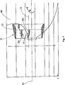
- Fig. 1 is the device 10 according to the invention in that immediately before the propeller of a hull 100, not shown in the drawing, a pre-nozzle 20 is provided with a cylindrical shape or a differently shaped shape or cross-sectional shape, the firmly attached to the hull. In the interior 20a of the pre-nozzle 20 fins or wings 30 are arranged. The pre-nozzle 20 is arranged rotationally symmetrical with the axis 21 shifted upwards on the hull.
- fins or wings 30a, 30b, 30c, 30d are arranged star-shaped with different fin or wing lengths in the interior 20a of the pre-nozzle 20. These four fins or wings are arranged asymmetrically within the pre-nozzle and radially to the propeller axis PA.
- the fins or wings 30a, 30b, 30c, 30d connect the pre-nozzle 20 to the hull 100 and are arranged at the rear end of the pre-nozzle 20 facing the propeller, wherein the curved side 32 of the wing-shaped or lenticular cross-sectional profile 31 of the fins or wings 30, 30a, 30b, 30c, 30d on the port side of the ship or on the upward-beating side of the propeller is directed upward and on the starboard side of the ship or downwardly striking side of the propeller down.
- the fins or wings 30a, 30b, 30c, 30d are also directed forward port side forward and starboard side forward down ( Fig. 2 and 3 ).
- the direction of rotation of the propeller is in the direction of arrow X ( Fig. 1 ).
- the fins or wings 30 and 30a, 30b, 30c, 30d arranged in the interior 20a of the pre-nozzle 20 are adjustable in their angular positions and can be locked in the set angular positions.
- the fins or wings have a lenticular cross-sectional profile 31 with a curved side wall 32 and with a rectilinear base 33.
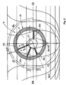
- the arrangement and the position of, for example, the two fins 30 to the propeller axis PA is such that the upper fin with its base 33 is approximately parallel to the propeller axis PA, whereas the lower fin assumes a position in which its base 33 at an angle a of at least 5 °, preferably 10 ° to the propeller axis PA is running. Other angular positions of the fins are possible.
- the fins 30a, 30b, 30c, 30d in Fig. 2 shown positions.
- the pre-nozzle 20 according to Fig. 1 and 6 is formed by a shaped body 25 having a cross-sectional profile 26 with an outer, at an angle to the propeller axis PA inclined wall portion 26a and with an inner rectilinear and parallel to the propeller axis PA extending wall portion 26b, 26c in the area facing away from the propeller an arcuate wall portion has, which merges into the outside wall portion 26 a.
- the outside wall section 26a may also be arcuate.
- the propeller side is at PS in Fig. 6 indicated.
- the device 10 is mounted at a small distance in front of the propeller 101 on the hull 100.
- the device 10 should be arranged as close as possible before the propeller 101.
- the pre-nozzle 20 is in this case about a horizontal, transverse axis, which preferably extends through the Vordüsenstoffddling, preferably by up to 8 °, rotated forward toward the front, arranged.
- the pre-nozzle 20 is 4 ° tilted forward.
- the pre-nozzle 20 with its trailing edge not more than 0.3 times fixed propeller diameter in front of the propeller plane.
- the pre-nozzle 20 may further be laterally, z. B. about a vertical axis, which preferably passes through the nozzle center, z. B. up to 3 °, are rotated so that the pre-nozzle on the upward-beating side of the propeller 101 is rotated forward.
- Optimal turns seem to be up to 1 °. Even 0 ° may be correct, but not in the other direction.
- the thickness of the profile of the pre-nozzle 20 is less than 12% of its length. Preferably, the thickness of the profile of the pre-nozzle 20 is 7.5% or 9% of its length.
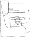
- the fins or wings 30, 30a, 30b, 30c, 30d may have a variable angle of attack in the radial direction, the fins or wings being twisted so that the fins or wings are directed upwards on the ship and the angle of attack decreases towards the front nozzle 20 ( Fig. 8 ).
- the thickness configuration of the profile of the pre-nozzle 20 and the configuration that the fins or wings 30, 30a, 30b, 30c, 30d in the radial direction have a variable angle of attack, are essential for very complete ships; They are also applicable to fast ships.
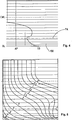
- FIG. 10 shows the power requirement for a 118,000 DWT bulk carrier with and without the device 10.
- the degree of thrust load is particularly high in very large slow ships.
- the diagram of Fig. 11 shows the possible power savings by the device 10 as a function of the C Th value. In the lower part of the Fig. 11 is given an assignment to ship types.
- the device according to the invention is characterized by the features specified in the description and the claims and by the in the Fig. 1 to 11 the drawings illustrated embodiments.
- the device 10 a novel propulsion enhancing device has been developed for complete slow-speed vessels that save fuel or run ships faster.
- the device consists of two combined fixedly mounted on the ship elements: a nozzle immediately in front of the propeller and a fin system integrated therein.
- the nozzle improves the propeller inflow in the area of unfavorable downstream flow and generates thrust itself; the fin system reduces the losses in the propeller jet and in the fan hub vortex by pre-twisting, whereby the propeller thrust is increased with the same drive power.
- the effects complement each other.
- the achievable power savings through the device are significantly dependent on the propeller load, ranging from 3% for small multipurpose vessels to 9% for large tankers and bulkers.
- the power savings are almost independent of the draft of the ship and the speed.
- the device is suitable for new buildings and for retrofitting.
Landscapes
- Engineering & Computer Science (AREA)
- Combustion & Propulsion (AREA)
- Mechanical Engineering (AREA)
- Ocean & Marine Engineering (AREA)
- Chemical & Material Sciences (AREA)
- Physics & Mathematics (AREA)
- Fluid Mechanics (AREA)
- Structures Of Non-Positive Displacement Pumps (AREA)
- Toys (AREA)
- Lubrication Of Internal Combustion Engines (AREA)
- Control Of Vehicle Engines Or Engines For Specific Uses (AREA)
- Hydraulic Turbines (AREA)
- Cylinder Crankcases Of Internal Combustion Engines (AREA)
- Automatic Cycles, And Cycles In General (AREA)
- Turbine Rotor Nozzle Sealing (AREA)
- Control Of Multiple Motors (AREA)
- General Details Of Gearings (AREA)
- Jet Pumps And Other Pumps (AREA)
- Wind Motors (AREA)
- Electrical Discharge Machining, Electrochemical Machining, And Combined Machining (AREA)
- Output Control And Ontrol Of Special Type Engine (AREA)
- Nozzles (AREA)
- Supply And Distribution Of Alternating Current (AREA)
Abstract
Description
Die Erfindung betrifft eine Vorrichtung zur Verringerung des Antriebsleistungsbedarfes eines Ein- oder Mehrschraubenschiffes, insbesondere für völlige und nichtvöllige, nicht sehr schnelle Schiffe.The invention relates to a device for reducing the power requirement of a single or multi-propeller ship, especially for complete and nichtvöllige, not very fast ships.
Aus der
Aus der
In der
Die
Aufgabe der vorliegenden Erfindung ist es, eine Vorrichtung zu schaffen, die der Verringerung des Antriebsleistungsbedarfes eines Schiffes dient. Außerdem soll eine Wirkungsgradverbesserung und eine Anpassung der Flossen bzw. Tragflügel an die Anströmung erreicht werden. Außerdem soll die Propelleranströmung verbessert werden.The object of the present invention is to provide a device which serves to reduce the drive power requirement of a ship. In addition, an improvement in efficiency and an adaptation of the fins or wings to the flow is to be achieved. In addition, the propeller inflow should be improved.
Gelöst wird diese Aufgabe durch eine Vorrichtung mit den Merkmalen des Anspruches 1.This object is achieved by a device having the features of
Hiernach ist die erfindungsgemäße Vorrichtung in der Weise ausgebildet, dass die in einem geringen Abstand vor dem Propeller am Schiffskörper angebrachte Vorrichtung aus einer Vordüse mit innerhalb der Vordüse angeordneten Flossen bzw. Tragflügeln besteht, wobei die Vordüse um eine horizontale, quer liegende Achse, die durch den Vordüsenmittelpunkt verläuft, bevorzugterweise um bis zu 8°, oben nach vorn gekippt sein kann.Thereafter, the device according to the invention is formed in such a way that the mounted at a small distance in front of the propeller on the hull device consists of a pre-nozzle with arranged within the pre-nozzle fins or vanes, wherein the pre-nozzle about a horizontal, transverse axis through extends the Vordüsenmittelpunkt, preferably by up to 8 °, can be tilted forward.
Mit einer derart ausgebildeten Vorrichtung ist es möglich, den Antriebsleistungsbedarf eines Schiffes zu verringern. Der mögliche Gewinn steigt mit zunehmendem Schubbelastungsgrad des Propellers. Die Vorrichtung eignet sich besonders für langsame, völlige Schiffe, wie Tanker, Bulker und Schlepper und auch für nicht sehr schnelle Schiffe aller Typen. Die Vorrichtung selbst ist vor dem Propeller des Schiffes fest am Schiffskörper angebracht und besteht aus den beiden Funktionselementen Vordüse und Flossen bzw. Tragflügel.With such a device, it is possible to reduce the drive power requirement of a ship. The potential profit increases with increasing thrust load of the propeller. The device is particularly suitable for slow, complete ships, such as tankers, bulkers and tugs and also for not very fast ships of all types. The device itself is firmly attached to the hull in front of the propeller of the ship and consists of the two functional elements pre-nozzle and fins or hydrofoils.
Dabei besteht das Wirkungsprinzip der Vordüse in der Erhöhung der Propelleranströmgeschwindigkeit in Gebieten sehr hohen Mitstromes und Verringerung der Propelleranströmgeschwindigkeit in Gebieten geringen Mitstromes, wobei die Düse selbst Schub erzeugt, und das der innerhalb der Vordüse angeordneten Flossen bzw. Tragflügel in der Erzeugung eines Vordralls, wobei beide Funktionselemente auf verschiedene Verlustquellen zielen, nämlich die Vordüse auf eine Verringerung der effektiven Schubbelastung und die Flossen bzw. Tragflügel auf eine Verringerung der Drallverluste im Propellerstrahl. Durch beide Effekte wird der Wirkungsgrad des Propulsionssystems erhöht.The principle of operation of the pre-nozzle is to increase the propeller inflow velocity in areas of very high concomitant flow and reduce the propeller inflow velocity in areas of low co-flux. wherein the nozzle itself generates thrust, and that of the fins disposed within the pre-nozzle in the production of a pre-whirl, both functional elements aimed at different sources of loss, namely the pre-nozzle to a reduction of the effective thrust load and the fins to a reduction the swirl losses in the propeller jet. Both effects increase the efficiency of the propulsion system.
Dadurch, dass die Vorrichtung so dicht wie möglich vor dem Propeller angebracht ist, wird eine höchstmögliche Wirkung erzielt, und zwar auch bei unterschiedlichen Ladefällen.The fact that the device is mounted as close as possible in front of the propeller, a maximum effect is achieved, even with different loading cases.
Hinzu kommt, dass die erfindungsgemäße Vorrichtung nicht nur für völlige Schiffe geeignet ist; sie kann bei allen nicht sehr schnellen Schiffen, etwa V ≤ 25 kn, mit gleicher Wirkung eingesetzt werden. Auch ein Einsatz für sehr große Containerschiffe ist möglich.In addition, the device according to the invention is not only suitable for complete ships; it can be used with equal effect on all ships that are not very fast, such as V ≤ 25 knots. A use for very large container ships is possible.
Ferner verbinden die Flossen bzw. Tragflügel den Schiffskörper mit der Vordüse.Furthermore, the fins or wings connect the hull with the pre-nozzle.
Die Flossen bzw. Tragflügel sind unsymmetrisch innerhalb der Vordüse und radial zur Propellerachse angeordnet.The fins or wings are arranged asymmetrically within the pre-nozzle and radially to the propeller axis.
Weitere vorteilhafte Ausgestaltungen sind Gegenstand der Unteransprüche.Further advantageous embodiments are the subject of the dependent claims.
Um eine höchstmögliche Wirkung zu erzielen, ist die Vorrichtung bzw. die Vordüse mit ihrer Hinterkante nicht weiter als 0,3 mal Propellerdurchmesser vor der Propellerebene fest angebracht. Vorzugsweise ist die Vordüse um etwa 4° oben nach vorn geneigt.In order to achieve the highest possible effect, the device or the pre-nozzle with its trailing edge is not more than 0.3 times propeller diameter fixedly mounted in front of the propeller plane. Preferably, the pre-nozzle is inclined forwards by about 4 °.
Nach einer weiteren Ausgestaltung ist die Vordüse um eine senkrechte Achse, die vorzugsweise durch den Vordüsenmittelpunkt verläuft, seitlich so verdreht, dass die Vordüse auf der aufwärts schlagenden Seite des Propellers nach vorn geneigt ist.According to a further embodiment, the pre-nozzle about a vertical axis, which preferably passes through the Vordüsenmittelpunkt, laterally so twisted that the pre-nozzle on the upward beating side of the propeller is inclined forward.
Die Erfindung sieht ferner vor, dass die Vordüse um eine senkrechte Achse, die vorzugsweise durch den Vordüsenmittelpunkt verläuft, seitlich um bis zu 3°, bevorzugterweise um 1°, so verdreht ist, dass die Vordüse auf der aufwärts schlagenden Seite des Propellers nach vorn gedreht ist, wobei die Drehung auch 0° sein kann, jedoch nicht in die andere Richtung.The invention further contemplates that the pre-nozzle is laterally rotated about a vertical axis, preferably through the pre-nozzle center, by up to 3 °, preferably 1 °, such that the pre-nozzle rotates forwardly on the upward-striking side of the propeller is, where the rotation can also be 0 °, but not in the other direction.
Ferner sieht die Erfindung vor, dass die Dicke des Profils der Vordüse weniger als 12 % seiner Länge beträgt. Vorteilhafterweise kann die Dicke des Profils der Vordüse 7,5 % oder 9 % seiner Länge betragen.Furthermore, the invention provides that the thickness of the profile of the pre-nozzle is less than 12% of its length. Advantageously, the thickness of the profile of the pre-nozzle can be 7.5% or 9% of its length.
Eine weitere Ausgestaltung sieht vor, dass die Flossen bzw. Tragflügel in radialer Richtung einen variablen Anstellwinkel besitzen, wobei die Flossen bzw. Tragflügel so verdreht (getwistet) sind, dass die Flossen bzw. Tragflügel innen am Schiff nach oben gerichtet sind und der Anstellwinkel nach außen zur Vordüse hin abnimmt.A further embodiment provides that the fins or wings have a variable angle of attack in the radial direction, wherein the fins or wings are twisted so that the fins or wings are directed upwards on the ship and the angle of attack decreases towards the front nozzle.
So ist die Vordüse rotationssymmetrisch mit nach oben verschobener bevorzugterweise oberhalb der Propellerachse liegenden Achse angeordnet, wobei der Innendurchmesser der Vordüse maximal 90 % des Propellerdurchmessers beträgt.Thus, the pre-nozzle is arranged rotationally symmetrical with the axis preferably displaced upwards above the propeller axis, the inner diameter of the pre-nozzle being at most 90% of the propeller diameter.
Bevorzugterweise sind die Flossen bzw. Tragflügel am hinteren Ende der Vordüse angeordnet, wobei die gewölbte Seite des tragflügelförmigen und auch linsenförmigen Querschnittsprofils der Flosse bzw. des Tragflügels auf der aufwärts schlagenden Seite des Propellers nach oben und auf der abwärts schlagenden Seite des Propellers nach unten gerichtet ist. Die Anordnung von vier Flossen bzw. Tragflügeln im Innenraum der Vordüse ist bevorzugt, stellt jedoch keinePreferably, the fins are located at the rear end of the pre-nozzle with the arcuate side of the wing-shaped and lenticular cross-sectional profile of the fin directed downwardly on the upwardly deflecting side of the propeller and downwardly on the downwardly propelled side of the propeller is. The arrangement of four fins in the interior of the pre-nozzle is preferred, but does not provide
Beschränkung dar, zumal auch eine geringe oder grössere Anzahl von Flossen bzw. Tragflügel vorgesehen sein kann.Restriction is, especially since a small or larger number of fins or wings can be provided.
In der Zeichnung sind Ausführungsbeispiele für ein Schiff mit einem über oben nach Steuerbord drehendem Propeller der erfindungsgemäßen Vorrichtung dargestellt und zwar zeigt:
- Fig. 1
- in einer Seitenansicht von Steuerbord die erfindungsgemäße aus einer Vordüse mit in deren Innenraum angeordneten Flossen bzw. Tragflügeln bestehenden Vorrichtung,
- Fig. 2
- die Vorrichtung in einer Ansicht von hinten, wobei die Flossen bzw. Tragflügel nicht angestellt dargestellt sind,
- Fig. 3
- einen vergrößerten Querschnitt durch das Profil einer Flosse bzw. eines Tragflügels;
- Fig. 4
- eine Seitenansicht der Heckkontur,
- Fig. 5
- einen Spantenriss des Hinterschiffes,
- Fig. 6
- die Vordüse mit in deren Innenraum angeordneten Flossen bzw. Tragflügeln gemäß
Fig. 1 mit Stellungsanordnungen der Flossen, - Fig. 7
- eine Seitenansicht der Vorrichtung mit um 4° oben nach vorn gekippter Vordüse,
- Fig. 8
- eine schaubildliche Ansicht der Vordüse mit innen am Schiff nach oben gerichteten und verdrehten (getwisteten) Flossen,
- Fig. 9
- ein Diagramm über Leistungseinsparungen bei Anwendung der erfindungsgemäßen Vorrichtung,
- Fig. 10
- ein Diagramm über den Leistungsbedarf mit und ohne der erfindungsgemäßen Vorrichtung und
- Fig. 11
- ein Diagramm zu Leistungseinsparungen bei Anwendung der erfindungsgemäßen Vorrichtung bei verschiedenen Schiffstypen.
- Fig. 1
- in a side view of starboard the inventive device consisting of a pre-nozzle with arranged in the interior of fins or wings existing device,
- Fig. 2
- the device in a view from the rear, wherein the fins or wings are shown not employed,
- Fig. 3
- an enlarged cross section through the profile of a fin or a wing;
- Fig. 4
- a side view of the rear contour,
- Fig. 5
- a frame crack of the rear,
- Fig. 6
- the pre-nozzle with arranged in their interior fins or wings according to
Fig. 1 with positions of the fins, - Fig. 7
- a side view of the device with 4 ° tilted forward tilted front nozzle,
- Fig. 8
- a perspective view of the pre-nozzle with inwardly upwardly directed and twisted (twisted) fins on the ship,
- Fig. 9
- a diagram of power savings when using the device according to the invention,
- Fig. 10
- a diagram of the power requirement with and without the device according to the invention and
- Fig. 11
- a diagram of power savings when using the device according to the invention in various types of ships.
Gemäß
Bei dem in
Nach einem Ausführungsbeispiel mit über oben nach Steuerbord drehendem Propeller nehmen die Flossen bzw. Tragflügel 30a, 30b, 30c, 30d folgende, bevorzugte radiale Winkelstellungen und Ausgangswinkelstellungen ein:
Nach der in
Die Vordüse 20 gemäß
Wie
Die Vordüse 20 kann des Weiteren um eine senkrechte Achse, die vorzugsweise durch den Düsenmittelpunkt verläuft, seitlich, z. B. bis zu 3°, so gedreht werden, dass die Vordüse auf der aufwärts schlagenden Seite des Propellers 101 nach vorn gedreht wird. Optimal scheinen hierbei Drehungen bis zu 1° zu sein. Auch 0° können zutreffend sein, aber nicht in die andere Richtung.The pre-nozzle 20 may further be laterally, z. B. about a vertical axis, which preferably passes through the nozzle center, z. B. up to 3 °, are rotated so that the pre-nozzle on the upward-beating side of the
Die Dicke des Profils der Vordüse 20 beträgt weniger als 12 % seiner Länge. Bevorzugterweise beträgt die Dicke des Profils der Vordüse 20 7,5 % oder 9 % seiner Länge.The thickness of the profile of the pre-nozzle 20 is less than 12% of its length. Preferably, the thickness of the profile of the pre-nozzle 20 is 7.5% or 9% of its length.
Die Flossen bzw. Tragflügel 30, 30a, 30b, 30c, 30d können in radialer Richtung einen variablen Anstellwinkel besitzen, wobei die Flossen bzw. Tragflügel so verdreht (getwistet) sind, dass die Flossen bzw. Tragflügel innen am Schiff nach oben gerichtet sind und der Anstellwinkel nach außen zur Vordüse 20 hin abnimmt (
Die Dickenausgestaltung des Profils der Vordüse 20 und die Ausgestaltung, dass die Flossen bzw. Tragflügel 30, 30a, 30b, 30c, 30d in radialer Richtung einen variablen Anstellwinkel besitzen, sind für sehr völlige Schiffe unerlässlich; sie sind auch bei schnellen Schiffen anwendbar.The thickness configuration of the profile of the pre-nozzle 20 and the configuration that the fins or
Durch die erfindungsgemäße Ausgestaltung der Vorrichtung 10 werden erhebliche Leistungseinsparungen erhalten, wie dies aus dem Diagramm der
Das Diagramm gemäß
Besonders hohe Gewinne sind z. B. bei Schiffen mit 12.000 DWT auf eine dicke Nabe bei einem Verstellpropeller zurückzuführen, deren Verluste durch die Vorrichtung 10 reduziert werden.Particularly high profits are z. As in ships with 12,000 DWT due to a thick hub in a variable pitch, the losses are reduced by the
Der Schubbelastungsgrad ist besonders groß bei sehr großen langsamen Schiffen. Das Diagramm der
Die erfindungsgemäße Vorrichtung ist gekennzeichnet durch die in der Beschreibung und den Ansprüchen angegebenen Merkmale und durch die in den
Mit der Vorrichtung 10 wurde eine neuartige, die Propulsion verbessernde Einrichtung für völlige langsame Schiffe, durch die Brennstoff eingespart wird oder Schiffe schneller fahren können, entwickelt. Die Vorrichtung besteht aus zwei kombinierten fest am Schiff angebrachten Elementen: einer Düse unmittelbar vor dem Propeller und einem darin integrierten Fin-System. Die Düse verbessert die Propellerzuströmung im Bereich ungünstigen Nachstromes und erzeugt selbst Schub; das Fin-System verringert durch Vordrallerzeugung die Verluste im Propellerstrahl und im Propellernabenwirbel, wodurch der Propellerschub bei gleicher Antriebsleistung erhöht wird. Die Wirkungen ergänzen sich.With the
Die erzielbaren Leistungseinsparungen durch die Vorrichtung sind wesentlich abhängig von der Propellerbelastung, sie reichen von 3 % bei kleinen Mehrzweckschiffen bis zu 9 % bei großen Tankern und Bulkern. Die Leistungseinsparungen sind nahezu unabhängig vom Tiefgang des Schiffes und von der Geschwindigkeit. Die Vorrichtung ist für Neubauten und zum Nachrüsten geeignet.The achievable power savings through the device are significantly dependent on the propeller load, ranging from 3% for small multipurpose vessels to 9% for large tankers and bulkers. The power savings are almost independent of the draft of the ship and the speed. The device is suitable for new buildings and for retrofitting.
- 1010
- Vorrichtungcontraption
- 2020
- Vordüseprenozzle
- 20a20a
- Innenrauminner space
- 2121
- Achse der VordüseAxis of the pre-nozzle
- 2525
- Formkörpermoldings
- 2626
- QuerschnittsprofilCross-sectional profile
- 26a26a
- Wandabschnittwall section
- 26b26b
- Wandabschnittwall section
- 26c26c
- Wandabschnittwall section
- 3030
- Flosse/TragflügelFin / Hydrofoil
- 30a30a
- Flosse/TragflügelFin / Hydrofoil
- 30b30b
- Flosse/TragflügelFin / Hydrofoil
- 30c30c
- Flosse/TragflügelFin / Hydrofoil
- 30d30d
- Flosse/TragflügelFin / Hydrofoil
- 3131
- QuerschnittsprofilCross-sectional profile
- 3232
- gewölbte Seitenwandarched sidewall
- 3333
- GrundflächeFloor space
- 100100
- Schiffskörperhull
- 101101
- Propellerpropeller
- BBBB
- Backbordport
- SBSB
- Steuerbordstarboard
- PAPA
- Propellerachsepropeller axis
- PSPS
- Propellerseitepropeller page
- XX
- Umlaufrichtung des PropellersDirection of rotation of the propeller
- αα
- Winkelangle
Claims (12)
- A single-propeller or multi-propeller ship, comprising a propeller (101) placed on a propeller axis (PA) and a device (10) for reducing the drive power requirement of the ship, wherein the device (10) installed on the hull (100) at a short distance in front of the propeller (101) consists of a fore-nozzle (20) with fins or hydrofoils (30; 30a, 30b, 30c, 30d) placed inside the fore-nozzle,
wherein the fore-nozzle, at the top thereof, is tilted forwards relative to a horizontal transverse axis that extends through the centre of the fore-nozzle,
characterized in
that the fins or hydrofoils (30; 30a, 30b, 30c, 30d) connect the hull to the fore-nozzle (20) and
that the fins or hydrofoils (30; 30a, 30b, 30c, 30d) are placed asymmetrically in the inner space (20a) of the fore-nozzle (20) and radially with respect to the propeller axis (PA). - The ship according to claim 1,
characterized in
that the trailing edge of the device or fore-nozzle (20) is affixed no further than 0.3 times the propeller diameter upstream of the propeller plane. - The ship according to any one of claims 1 or 2,
characterized in
that the fore-nozzle (20), at the top, is tilted forwards by approximately 4°. - The ship according to any one of claims 1 to 3,
characterized in
that the fore-nozzle (20) is laterally rotated about a vertical axis such that the fore-nozzle (20) is shifted forwards on the upwards-striking side of the propeller (101). - The ship according to claim 4,
characterized in
that the fore-nozzle (20) is laterally rotatable by up to 3° about a vertical axis which preferably extends through the centre of the fore-nozzle, such that the fore-nozzle (20) is rotated forwards on the upwards-striking side of the propeller (101). - The ship according to any one of the preceding claims 1 to 5,
characterized in
that the thickness of the profile of the fore-nozzle (20) is less than 12 % of its length. - The ship according to claim 6,
characterized in
that the thickness of the profile of the fore-nozzle is 7.5 % or 9 % of its length. - The ship according to any one of the preceding claims 1 to 7,
characterized in
that the fins or hydrofoils (30; 30a, 30b, 30c, 30d) in radial direction comprise a variable angle of attack, wherein the fins or hydrofoils are twisted such that said fins or hydrofoils on the inside of the ship are oriented upwards, and the angle of attack decreases outwards towards the fore-nozzle (20). - The ship according to any one of the preceding claims 1 to 8,
characterized in
that the fore-nozzle (20) having an inner diameter which is less than 90 % of the propeller diameter is rotationally symmetrically placed about an axis (21) being offset above the propeller axis (PA). - The ship according to any one of the preceding claims 1 to 9,
characterized in
that the fins or hydrofoils are placed at the rear end of the fore-nozzle (20), wherein the vaulted side (32) of the lentiform cross-sectional profile (31) of the fin or of the hydrofoil (30; 30a, 30b, 30c, 30d) is oriented upwards on the upwards-striking side of the propeller, and is directed downwards on the downwards-striking side of the propeller. - The ship according to any one of the preceding claims 1 to 10,
characterized in
that the fins or hydrofoils (30; 30a, 30b, 30c, 30d) assume the following preferred radial angular positions and initial angular positions:Fin angle Angle of attack Port (BB) Lower fin (30a) 247.5° 14° Port (BB) Middle fin (30b) 292.5° 12° Port (BB) Upper fin (30c) 337.5° 8° Starboard (SB) Fin (30d) 90.0° 10° - The ship according to any one of the preceding claims 1 to 11,
characterized in
that the fins or hydrofoils (30) placed in the inner space (20a) of the fore-nozzle (20) are variable or adjustable with respect to their angular positions.
Priority Applications (4)
| Application Number | Priority Date | Filing Date | Title |
|---|---|---|---|
| PL09003150T PL2100809T3 (en) | 2008-03-10 | 2009-03-05 | Device for lowering the drive output requirements of a ship |
| EP20090003150 EP2100809B1 (en) | 2008-03-10 | 2009-03-05 | Device for lowering the drive output requirements of a ship |
| HRP20150791TT HRP20150791T1 (en) | 2008-03-10 | 2015-07-17 | Device for lowering the drive output requirements of a ship |
| CY20151100643T CY1116586T1 (en) | 2008-03-10 | 2015-07-21 | DEVICE TO REDUCE THE POWER TRANSMISSION REQUIREMENT |
Applications Claiming Priority (5)
| Application Number | Priority Date | Filing Date | Title |
|---|---|---|---|
| DE202008003367 | 2008-03-10 | ||
| DE202008006069U DE202008006069U1 (en) | 2008-03-10 | 2008-05-02 | Device for reducing the power requirement of a ship |
| EP08010940A EP2100808B1 (en) | 2008-03-10 | 2008-06-17 | Device for lowering the drive output requirements of a ship |
| DE202009002642U DE202009002642U1 (en) | 2008-03-10 | 2009-02-26 | Device for reducing the power requirement of a ship |
| EP20090003150 EP2100809B1 (en) | 2008-03-10 | 2009-03-05 | Device for lowering the drive output requirements of a ship |
Publications (3)
| Publication Number | Publication Date |
|---|---|
| EP2100809A2 EP2100809A2 (en) | 2009-09-16 |
| EP2100809A3 EP2100809A3 (en) | 2009-12-02 |
| EP2100809B1 true EP2100809B1 (en) | 2015-04-22 |
Family
ID=39628645
Family Applications (2)
| Application Number | Title | Priority Date | Filing Date |
|---|---|---|---|
| EP08010940A Active EP2100808B1 (en) | 2008-03-10 | 2008-06-17 | Device for lowering the drive output requirements of a ship |
| EP20090003150 Active EP2100809B1 (en) | 2008-03-10 | 2009-03-05 | Device for lowering the drive output requirements of a ship |
Family Applications Before (1)
| Application Number | Title | Priority Date | Filing Date |
|---|---|---|---|
| EP08010940A Active EP2100808B1 (en) | 2008-03-10 | 2008-06-17 | Device for lowering the drive output requirements of a ship |
Country Status (18)
| Country | Link |
|---|---|
| US (2) | US8430703B2 (en) |
| EP (2) | EP2100808B1 (en) |
| JP (2) | JP4931879B2 (en) |
| KR (1) | KR101229204B1 (en) |
| CN (2) | CN101531247B (en) |
| AT (1) | ATE512875T1 (en) |
| CA (2) | CA2637875C (en) |
| CY (1) | CY1116586T1 (en) |
| DE (1) | DE202008006069U1 (en) |
| DK (2) | DK2100808T3 (en) |
| ES (2) | ES2365363T3 (en) |
| HK (2) | HK1131948A1 (en) |
| HR (2) | HRP20110502T1 (en) |
| NO (1) | NO20083124L (en) |
| PL (2) | PL2100808T3 (en) |
| PT (2) | PT2100808E (en) |
| SG (1) | SG155818A1 (en) |
| TW (2) | TWI370789B (en) |
Families Citing this family (31)
| Publication number | Priority date | Publication date | Assignee | Title |
|---|---|---|---|---|
| US8992422B2 (en) | 2006-03-23 | 2015-03-31 | Ethicon Endo-Surgery, Inc. | Robotically-controlled endoscopic accessory channel |
| DE202008006069U1 (en) * | 2008-03-10 | 2008-07-17 | Becker Marine Systems Gmbh & Co. Kg | Device for reducing the power requirement of a ship |
| KR101023052B1 (en) * | 2009-09-17 | 2011-03-24 | 대우조선해양 주식회사 | Ducted pre-swirl stator |
| JP2011168075A (en) * | 2010-02-16 | 2011-09-01 | Kawasaki Heavy Ind Ltd | Thruster with duct and vessel including the same |
| TWI508897B (en) * | 2010-09-07 | 2015-11-21 | Akishima Lab Mitsui Zosen Inc | Ship propulsion system and ship |
| TWI491536B (en) * | 2010-09-10 | 2015-07-11 | Akishima Lab Mitsui Zosen Inc | Ship propulsion system and ship |
| DE202011000439U1 (en) * | 2011-02-25 | 2012-08-21 | Becker Marine Systems Gmbh & Co. Kg | Pre-nozzle for a propulsion system of a watercraft to improve energy efficiency |
| KR101723240B1 (en) * | 2011-05-13 | 2017-04-18 | 현대중공업 주식회사 | Propeller Duct Structure of Ship with Multi-Column Fin |
| KR20130021052A (en) * | 2011-08-22 | 2013-03-05 | 현대중공업 주식회사 | Asymmetric twisted flow control fin of ship |
| KR101365878B1 (en) * | 2011-08-22 | 2014-02-24 | 현대중공업 주식회사 | Forming method for stern structure of a ship attached with asymmetric twisted flow control fin |
| PL2591994T3 (en) * | 2011-11-11 | 2015-03-31 | Becker Marine Sys Gmbh & Co Kg | Device for lowering the fuel consumption of the propulsion of a watercraft |
| DE102012201539A1 (en) * | 2012-02-02 | 2013-08-08 | Siemens Aktiengesellschaft | Gaining data about a state of a liquid |
| KR101402484B1 (en) * | 2012-05-15 | 2014-06-11 | 현대중공업 주식회사 | A propulsion apparatus for ship |
| KR101424328B1 (en) * | 2012-05-21 | 2014-08-04 | 현대중공업 주식회사 | A propulsion apparatus for ship |
| KR101381497B1 (en) * | 2012-07-27 | 2014-04-10 | 현대중공업 주식회사 | A propulsion apparatus for ship |
| KR101381526B1 (en) * | 2012-07-27 | 2014-04-10 | 현대중공업 주식회사 | A propulsion apparatus for ship |
| JP5901512B2 (en) * | 2012-12-27 | 2016-04-13 | 三菱重工業株式会社 | Duct device and ship using the same |
| DE202013101943U1 (en) * | 2013-05-06 | 2013-06-11 | Becker Marine Systems Gmbh & Co. Kg | Device for reducing the power requirement of a watercraft |
| CN103332280B (en) * | 2013-07-01 | 2017-09-29 | 中国船舶科学研究中心上海分部 | Radiance type preposed guide wheel |
| KR101534284B1 (en) * | 2013-07-26 | 2015-07-07 | 에스티엑스마린서비스(주) | Apparatus for Improving Thrust of Ship |
| US9962161B2 (en) | 2014-02-12 | 2018-05-08 | Ethicon Llc | Deliverable surgical instrument |
| DE102015103285A1 (en) * | 2015-03-06 | 2016-09-08 | Becker Marine Systems Gmbh & Co. Kg | Arrangement for multi-propeller ships with external propeller shafts and method for producing such an arrangement |
| JP6663144B2 (en) * | 2015-03-20 | 2020-03-11 | 国立研究開発法人 海上・港湾・航空技術研究所 | Ship equipped with air lubrication control device |
| CN105346698A (en) * | 2015-12-02 | 2016-02-24 | 南通虹波机械有限公司 | Efficient energy-saving guide wheel |
| US10597118B2 (en) | 2016-09-12 | 2020-03-24 | Kai Concepts, LLC | Watercraft device with hydrofoil and electric propeller system |
| JP2018111449A (en) * | 2017-01-13 | 2018-07-19 | 株式会社三井E&Sホールディングス | Vessel |
| US10946939B1 (en) | 2020-04-22 | 2021-03-16 | Kai Concepts, LLC | Watercraft having a waterproof container and a waterproof electrical connector |
| US11897583B2 (en) | 2020-04-22 | 2024-02-13 | Kai Concepts, LLC | Watercraft device with hydrofoil and electric propulsion system |
| US11485457B1 (en) | 2021-06-14 | 2022-11-01 | Kai Concepts, LLC | Hydrojet propulsion system |
| US11878775B2 (en) | 2021-07-13 | 2024-01-23 | Kai Concepts, LLC | Leash system and methods of use |
| CN115056951B (en) * | 2022-05-23 | 2024-03-22 | 中国船舶工业集团公司第七0八研究所 | Hyperbolic rectifying wing for ship |
Citations (1)
| Publication number | Priority date | Publication date | Assignee | Title |
|---|---|---|---|---|
| JPS5726086A (en) * | 1980-07-19 | 1982-02-12 | Mitsubishi Heavy Ind Ltd | Device for improving propelling performance of ship |
Family Cites Families (51)
| Publication number | Priority date | Publication date | Assignee | Title |
|---|---|---|---|---|
| US3455268A (en) | 1966-10-13 | 1969-07-15 | Samuel J Gordon | Nonsymmetric shroud-propeller combination for directional control |
| GB1203001A (en) * | 1968-03-06 | 1970-08-26 | Nat Res Dev | Improvements in and relating to electrochemical cells |
| GB1308310A (en) | 1969-05-19 | 1973-02-21 | Lips Nv | Ships propeller shrouded by a nozzle |
| JPS537096A (en) | 1976-07-06 | 1978-01-23 | Mitsui Eng & Shipbuild Co Ltd | Ship |
| JPS543797A (en) * | 1977-06-08 | 1979-01-12 | Mitsui Eng & Shipbuild Co Ltd | Ship |
| ES8100010A1 (en) * | 1979-11-02 | 1980-07-16 | Espanoles Astilleros | Tubular duct for a ship propeller |
| JPS5632396Y2 (en) | 1979-09-06 | 1981-08-01 | ||
| JPS5722994A (en) * | 1980-07-16 | 1982-02-06 | Mitsubishi Heavy Ind Ltd | Device for improving propulsion performance of ship |
| JPS5726087A (en) * | 1980-07-22 | 1982-02-12 | Mitsubishi Heavy Ind Ltd | Device for improving propelling performance of ship |
| JPS57158191A (en) | 1981-03-26 | 1982-09-29 | Mitsubishi Heavy Ind Ltd | Fin type device for improving propelling performance |
| JPS58492A (en) | 1981-06-24 | 1983-01-05 | Mitsubishi Heavy Ind Ltd | Device for improving propulsion efficiency of ship |
| JPS58493A (en) | 1981-06-25 | 1983-01-05 | Mitsubishi Heavy Ind Ltd | Device for improving propulsion efficiency of ship |
| JPS584695A (en) | 1981-06-29 | 1983-01-11 | Mitsubishi Heavy Ind Ltd | Marine reaction fine |
| JPS5816981A (en) * | 1981-07-18 | 1983-01-31 | Nippon Kokan Kk <Nkk> | Wring propeller with duct |
| JPS58139395A (en) * | 1982-02-10 | 1983-08-18 | Nec Ic Microcomput Syst Ltd | Shift register |
| JPS58139395U (en) * | 1982-03-16 | 1983-09-19 | 三菱重工業株式会社 | Reaction Fin |
| DE3216578C1 (en) | 1982-05-04 | 1983-10-13 | Herbert Prof. Dr.-Ing. 5100 Aachen Schneekluth | Flow control surface at the stern of screw-in ships |
| DE8314111U1 (en) | 1983-05-13 | 1984-02-23 | Punson, Jurij Sergeevič, Leningrad | ship |
| DE3324753A1 (en) | 1983-07-06 | 1985-01-17 | Hermann Dr.-Ing. 1000 Berlin Grothues-Spork | ARRANGEMENT FOR INFLUENCING THE PROPELLER FLOW |
| JPS60127299A (en) * | 1983-12-14 | 1985-07-06 | Sumitomo Electric Ind Ltd | Gas-phase synthesis of diamond |
| JPS60127299U (en) | 1984-02-07 | 1985-08-27 | 三菱重工業株式会社 | Reaction Fin |
| SE8402792L (en) | 1984-05-23 | 1985-11-24 | Kamewa Ab | thruster |
| JPS6136499A (en) * | 1984-07-27 | 1986-02-21 | 株式会社小松製作所 | Controller for inflow of soil and sand of underground excavator |
| JPS6136499U (en) | 1984-08-08 | 1986-03-06 | 三菱重工業株式会社 | Ship turning motion control device |
| JPH0637630B2 (en) * | 1985-03-05 | 1994-05-18 | 出光興産株式会社 | Lubricating oil composition for 4-cycle engine |
| JPS61203199U (en) | 1985-06-11 | 1986-12-20 | ||
| DE3615619A1 (en) * | 1985-06-24 | 1987-01-02 | Schiffbau Veb K | CONTROL DEVICE FOR INFLUENCING THE PROPELLER INFLOW IN SHIPS |
| JPH0654359B2 (en) * | 1986-12-15 | 1994-07-20 | 日本碍子株式会社 | Solid waste compression and volume reduction equipment |
| JPS63173791A (en) | 1987-01-12 | 1988-07-18 | Mitsubishi Heavy Ind Ltd | Rudder having nozzle |
| US4932908A (en) | 1988-03-03 | 1990-06-12 | United States Of America | Energy efficient asymmetric pre-swirl vane and twisted propeller propulsion system |
| US5209642A (en) * | 1988-03-03 | 1993-05-11 | The United States Of America As Represented By The Secretary Of Transportation | Modified optimum pitch propeller |
| JPH0443193A (en) | 1990-06-08 | 1992-02-13 | Hitachi Zosen Corp | Nozzle rudder |
| DE4025339C2 (en) | 1990-08-10 | 1999-07-08 | Schneekluth Herbert | Control system |
| JP2948413B2 (en) * | 1991-11-14 | 1999-09-13 | 三菱重工業株式会社 | Reaction fin device for ships |
| DE4223570C1 (en) | 1992-07-17 | 1993-09-16 | Herbert Prof. Dr.-Ing. 5100 Aachen De Schneekluth | Streamline control for variable pitch marine screw - has ring duct with smaller diameter than screw to reduce flow rate around hub and increase flow rate through propeller blades |
| JP3329870B2 (en) | 1993-02-18 | 2002-09-30 | 株式会社東芝 | Charger |
| JPH07267189A (en) | 1994-03-31 | 1995-10-17 | Mitsubishi Heavy Ind Ltd | Marine propeller device with current fin |
| GB2303832B (en) * | 1995-04-11 | 1998-02-11 | Mitsui Shipbuilding Eng | Ship |
| JP3235772B2 (en) | 1995-12-22 | 2001-12-04 | 住友重機械工業株式会社 | Ship with stern duct |
| US5906522A (en) | 1998-04-01 | 1999-05-25 | Hooper; Robert P. | Thrust enhancer for marine propeller |
| JP4153750B2 (en) * | 2002-08-13 | 2008-09-24 | 三菱重工業株式会社 | Ship |
| JP4079742B2 (en) | 2002-10-10 | 2008-04-23 | ユニバーサル造船株式会社 | Duct bodies in ships |
| JP2004306839A (en) * | 2003-04-09 | 2004-11-04 | Mitsubishi Heavy Ind Ltd | Ship |
| US6986689B2 (en) | 2003-07-22 | 2006-01-17 | Enviropropcorporation | System and apparatus for improving safety and thrust from a hydro-drive device |
| US7267589B2 (en) | 2004-07-22 | 2007-09-11 | Enviroprop Corporation | System and apparatus for improving safety and thrust from a hydro-drive device |
| US7229331B2 (en) | 2005-01-24 | 2007-06-12 | Enviroprop Corporation | Shroud for a hydro thrust device |
| KR100640299B1 (en) | 2005-04-14 | 2006-10-30 | 대우조선해양 주식회사 | Installation structure for preswirl stator of ship |
| JP4684778B2 (en) | 2005-06-15 | 2011-05-18 | エムエイチアイマリンエンジニアリング株式会社 | Small ship propulsion performance improvement device |
| JP5081455B2 (en) * | 2007-01-19 | 2012-11-28 | 大宇造船海洋株式会社 | Asymmetrical front wing of a ship |
| DK1955944T3 (en) * | 2007-02-06 | 2012-09-17 | Daewoo Shipbuilding & Marine | Asymmetric pre-swirl stator for ship |
| DE202008006069U1 (en) * | 2008-03-10 | 2008-07-17 | Becker Marine Systems Gmbh & Co. Kg | Device for reducing the power requirement of a ship |
-
2008
- 2008-05-02 DE DE202008006069U patent/DE202008006069U1/en not_active Expired - Lifetime
- 2008-06-17 PT PT08010940T patent/PT2100808E/en unknown
- 2008-06-17 EP EP08010940A patent/EP2100808B1/en active Active
- 2008-06-17 ES ES08010940T patent/ES2365363T3/en active Active
- 2008-06-17 PL PL08010940T patent/PL2100808T3/en unknown
- 2008-06-17 AT AT08010940T patent/ATE512875T1/en active
- 2008-06-17 DK DK08010940.8T patent/DK2100808T3/en active
- 2008-07-14 NO NO20083124A patent/NO20083124L/en not_active Application Discontinuation
- 2008-07-16 CA CA2637875A patent/CA2637875C/en active Active
- 2008-07-30 US US12/221,065 patent/US8430703B2/en active Active
- 2008-07-31 JP JP2008197694A patent/JP4931879B2/en active Active
- 2008-08-06 SG SG200805850-5A patent/SG155818A1/en unknown
- 2008-08-08 KR KR1020080077792A patent/KR101229204B1/en active IP Right Grant
- 2008-08-18 CN CN2008101449582A patent/CN101531247B/en active Active
- 2008-08-19 TW TW097131514A patent/TWI370789B/en not_active IP Right Cessation
-
2009
- 2009-03-05 DK DK09003150.1T patent/DK2100809T3/en active
- 2009-03-05 PT PT90031501T patent/PT2100809E/en unknown
- 2009-03-05 PL PL09003150T patent/PL2100809T3/en unknown
- 2009-03-05 EP EP20090003150 patent/EP2100809B1/en active Active
- 2009-03-05 ES ES09003150.1T patent/ES2542307T3/en active Active
- 2009-03-07 US US12/381,149 patent/US8123578B2/en not_active Expired - Fee Related
- 2009-03-09 TW TW098107532A patent/TWI377155B/en not_active IP Right Cessation
- 2009-03-09 JP JP2009054524A patent/JP4745411B2/en active Active
- 2009-03-09 CA CA2657477A patent/CA2657477C/en not_active Expired - Fee Related
- 2009-03-09 CN CN2009101346010A patent/CN101531246B/en active Active
- 2009-10-23 HK HK09109839.7A patent/HK1131948A1/en unknown
- 2009-11-10 HK HK09110442.4A patent/HK1132970A1/en not_active IP Right Cessation
-
2011
- 2011-07-06 HR HR20110502T patent/HRP20110502T1/en unknown
-
2015
- 2015-07-17 HR HRP20150791TT patent/HRP20150791T1/en unknown
- 2015-07-21 CY CY20151100643T patent/CY1116586T1/en unknown
Patent Citations (1)
| Publication number | Priority date | Publication date | Assignee | Title |
|---|---|---|---|---|
| JPS5726086A (en) * | 1980-07-19 | 1982-02-12 | Mitsubishi Heavy Ind Ltd | Device for improving propelling performance of ship |
Also Published As
Similar Documents
| Publication | Publication Date | Title |
|---|---|---|
| EP2100809B1 (en) | Device for lowering the drive output requirements of a ship | |
| EP2591994B1 (en) | Device for lowering the fuel consumption of the propulsion of a watercraft | |
| DE69122884T2 (en) | PROPELLER WITH COAT RING ATTACHED TO THE WINGS | |
| EP2994379B1 (en) | Apparatus to reduce required propulsion power of waterborne vessel | |
| EP2597029B1 (en) | Pre-nozzle for a drive system of a water vehicle for improving energy efficiency | |
| EP2277772B1 (en) | Ducted propeller for ships | |
| EP2060482B1 (en) | Kort nozzle | |
| EP2060484A1 (en) | Rudder for ships | |
| DE1528824B2 (en) | Axial fluid flow machine with reversible working direction | |
| DE60016873T2 (en) | Impeller of a water jet propulsion device for watercraft | |
| DE69110040T2 (en) | Oars. | |
| EP0131115A2 (en) | Arrangement for influencing the current falling onto a propeller | |
| EP2281743B1 (en) | Propeller engine pod | |
| EP0540868B1 (en) | Flow guiding device | |
| EP3386854B1 (en) | Giroplane rotor blade | |
| DE202009002642U1 (en) | Device for reducing the power requirement of a ship | |
| DD241056A1 (en) | DEVICE FOR INCREASING THE EFFICIENCY OF SHIP PROPELLERS | |
| DE2625818C2 (en) | ||
| EP2730772B1 (en) | Nozzle with baffles | |
| DE102010022070A1 (en) | Drive unit for watercraft, has driving element comprising drive blades that include convex outer surface edge and concave inner surface edge in cross-section, where drive blades are helically arranged at radial distance around shaft | |
| DE68911913T2 (en) | DOUBLE GUIDE NOZZLE. | |
| WO2021239963A1 (en) | Arrangement for reducing a drive power requirement of a watercraft | |
| DE3410940A1 (en) | Rudder with blades and method of manufacturing it | |
| DD267383A3 (en) | LEADING INSTRUMENT FOR INFLUENCING PROPELLER STIMULATION ON INLAND VESSELS | |
| DE1781128A1 (en) | Hull |
Legal Events
| Date | Code | Title | Description |
|---|---|---|---|
| PUAI | Public reference made under article 153(3) epc to a published international application that has entered the european phase |
Free format text: ORIGINAL CODE: 0009012 |
|
| AK | Designated contracting states |
Kind code of ref document: A2 Designated state(s): AT BE BG CH CY CZ DE DK EE ES FI FR GB GR HR HU IE IS IT LI LT LU LV MC MK MT NL NO PL PT RO SE SI SK TR |
|
| AX | Request for extension of the european patent |
Extension state: AL BA RS |
|
| PUAL | Search report despatched |
Free format text: ORIGINAL CODE: 0009013 |
|
| AK | Designated contracting states |
Kind code of ref document: A3 Designated state(s): AT BE BG CH CY CZ DE DK EE ES FI FR GB GR HR HU IE IS IT LI LT LU LV MC MK MT NL NO PL PT RO SE SI SK TR |
|
| AX | Request for extension of the european patent |
Extension state: AL BA RS |
|
| 17P | Request for examination filed |
Effective date: 20091110 |
|
| AKX | Designation fees paid |
Designated state(s): AT BE BG CH CY CZ DE DK EE ES FI FR GB GR HR HU IE IS IT LI LT LU LV MC MK MT NL NO PL PT RO SE SI SK TR |
|
| 17Q | First examination report despatched |
Effective date: 20110908 |
|
| RAP1 | Party data changed (applicant data changed or rights of an application transferred) |
Owner name: BECKER MARINE SYSTEMS GMBH & CO. KG |
|
| GRAP | Despatch of communication of intention to grant a patent |
Free format text: ORIGINAL CODE: EPIDOSNIGR1 |
|
| INTG | Intention to grant announced |
Effective date: 20141105 |
|
| GRAS | Grant fee paid |
Free format text: ORIGINAL CODE: EPIDOSNIGR3 |
|
| GRAA | (expected) grant |
Free format text: ORIGINAL CODE: 0009210 |
|
| AK | Designated contracting states |
Kind code of ref document: B1 Designated state(s): AT BE BG CH CY CZ DE DK EE ES FI FR GB GR HR HU IE IS IT LI LT LU LV MC MK MT NL NO PL PT RO SE SI SK TR |
|
| REG | Reference to a national code |
Ref country code: GB Ref legal event code: FG4D Free format text: NOT ENGLISH |
|
| REG | Reference to a national code |
Ref country code: CH Ref legal event code: EP |
|
| REG | Reference to a national code |
Ref country code: AT Ref legal event code: REF Ref document number: 723051 Country of ref document: AT Kind code of ref document: T Effective date: 20150515 |
|
| REG | Reference to a national code |
Ref country code: IE Ref legal event code: FG4D Free format text: LANGUAGE OF EP DOCUMENT: GERMAN |
|
| REG | Reference to a national code |
Ref country code: DE Ref legal event code: R096 Ref document number: 502009010928 Country of ref document: DE Effective date: 20150603 |
|
| REG | Reference to a national code |
Ref country code: HR Ref legal event code: TUEP Ref document number: P20150791 Country of ref document: HR |
|
| REG | Reference to a national code |
Ref country code: RO Ref legal event code: EPE |
|
| REG | Reference to a national code |
Ref country code: DK Ref legal event code: T3 Effective date: 20150720 |
|
| REG | Reference to a national code |
Ref country code: SE Ref legal event code: TRGR Ref country code: ES Ref legal event code: FG2A Ref document number: 2542307 Country of ref document: ES Kind code of ref document: T3 Effective date: 20150804 |
|
| REG | Reference to a national code |
Ref country code: NL Ref legal event code: T3 |
|
| REG | Reference to a national code |
Ref country code: HR Ref legal event code: T1PR Ref document number: P20150791 Country of ref document: HR |
|
| REG | Reference to a national code |
Ref country code: PT Ref legal event code: SC4A Free format text: AVAILABILITY OF NATIONAL TRANSLATION Effective date: 20150713 |
|
| REG | Reference to a national code |
Ref country code: NO Ref legal event code: T2 Effective date: 20150422 |
|
| REG | Reference to a national code |
Ref country code: LT Ref legal event code: MG4D |
|
| PG25 | Lapsed in a contracting state [announced via postgrant information from national office to epo] |
Ref country code: LT Free format text: LAPSE BECAUSE OF FAILURE TO SUBMIT A TRANSLATION OF THE DESCRIPTION OR TO PAY THE FEE WITHIN THE PRESCRIBED TIME-LIMIT Effective date: 20150422 |
|
| REG | Reference to a national code |
Ref country code: PL Ref legal event code: T3 |
|
| REG | Reference to a national code |
Ref country code: GR Ref legal event code: EP Ref document number: 20150401524 Country of ref document: GR Effective date: 20150901 |
|
| PG25 | Lapsed in a contracting state [announced via postgrant information from national office to epo] |
Ref country code: LV Free format text: LAPSE BECAUSE OF FAILURE TO SUBMIT A TRANSLATION OF THE DESCRIPTION OR TO PAY THE FEE WITHIN THE PRESCRIBED TIME-LIMIT Effective date: 20150422 Ref country code: IS Free format text: LAPSE BECAUSE OF FAILURE TO SUBMIT A TRANSLATION OF THE DESCRIPTION OR TO PAY THE FEE WITHIN THE PRESCRIBED TIME-LIMIT Effective date: 20150822 |
|
| REG | Reference to a national code |
Ref country code: DE Ref legal event code: R097 Ref document number: 502009010928 Country of ref document: DE |
|
| PG25 | Lapsed in a contracting state [announced via postgrant information from national office to epo] |
Ref country code: EE Free format text: LAPSE BECAUSE OF FAILURE TO SUBMIT A TRANSLATION OF THE DESCRIPTION OR TO PAY THE FEE WITHIN THE PRESCRIBED TIME-LIMIT Effective date: 20150422 |
|
| REG | Reference to a national code |
Ref country code: HR Ref legal event code: ODRP Ref document number: P20150791 Country of ref document: HR Payment date: 20160225 Year of fee payment: 8 |
|
| PLBE | No opposition filed within time limit |
Free format text: ORIGINAL CODE: 0009261 |
|
| STAA | Information on the status of an ep patent application or granted ep patent |
Free format text: STATUS: NO OPPOSITION FILED WITHIN TIME LIMIT |
|
| PG25 | Lapsed in a contracting state [announced via postgrant information from national office to epo] |
Ref country code: CZ Free format text: LAPSE BECAUSE OF FAILURE TO SUBMIT A TRANSLATION OF THE DESCRIPTION OR TO PAY THE FEE WITHIN THE PRESCRIBED TIME-LIMIT Effective date: 20150422 Ref country code: SK Free format text: LAPSE BECAUSE OF FAILURE TO SUBMIT A TRANSLATION OF THE DESCRIPTION OR TO PAY THE FEE WITHIN THE PRESCRIBED TIME-LIMIT Effective date: 20150422 |
|
| REG | Reference to a national code |
Ref country code: FR Ref legal event code: PLFP Year of fee payment: 8 |
|
| 26N | No opposition filed |
Effective date: 20160125 |
|
| PGFP | Annual fee paid to national office [announced via postgrant information from national office to epo] |
Ref country code: ES Payment date: 20160322 Year of fee payment: 8 Ref country code: DK Payment date: 20160322 Year of fee payment: 8 Ref country code: NO Payment date: 20160321 Year of fee payment: 8 Ref country code: TR Payment date: 20160224 Year of fee payment: 8 Ref country code: NL Payment date: 20160322 Year of fee payment: 8 |
|
| PG25 | Lapsed in a contracting state [announced via postgrant information from national office to epo] |
Ref country code: SI Free format text: LAPSE BECAUSE OF FAILURE TO SUBMIT A TRANSLATION OF THE DESCRIPTION OR TO PAY THE FEE WITHIN THE PRESCRIBED TIME-LIMIT Effective date: 20150422 |
|
| PGFP | Annual fee paid to national office [announced via postgrant information from national office to epo] |
Ref country code: PL Payment date: 20160302 Year of fee payment: 8 Ref country code: RO Payment date: 20160229 Year of fee payment: 8 Ref country code: HR Payment date: 20160225 Year of fee payment: 8 Ref country code: FR Payment date: 20160322 Year of fee payment: 8 Ref country code: PT Payment date: 20160225 Year of fee payment: 8 Ref country code: GR Payment date: 20160318 Year of fee payment: 8 Ref country code: BE Payment date: 20160322 Year of fee payment: 8 Ref country code: SE Payment date: 20160322 Year of fee payment: 8 Ref country code: FI Payment date: 20160318 Year of fee payment: 8 Ref country code: GB Payment date: 20160322 Year of fee payment: 8 |
|
| PGFP | Annual fee paid to national office [announced via postgrant information from national office to epo] |
Ref country code: CY Payment date: 20160226 Year of fee payment: 8 |
|
| PGFP | Annual fee paid to national office [announced via postgrant information from national office to epo] |
Ref country code: IT Payment date: 20160318 Year of fee payment: 8 |
|
| PG25 | Lapsed in a contracting state [announced via postgrant information from national office to epo] |
Ref country code: MC Free format text: LAPSE BECAUSE OF FAILURE TO SUBMIT A TRANSLATION OF THE DESCRIPTION OR TO PAY THE FEE WITHIN THE PRESCRIBED TIME-LIMIT Effective date: 20150422 Ref country code: LU Free format text: LAPSE BECAUSE OF FAILURE TO SUBMIT A TRANSLATION OF THE DESCRIPTION OR TO PAY THE FEE WITHIN THE PRESCRIBED TIME-LIMIT Effective date: 20160305 |
|
| REG | Reference to a national code |
Ref country code: CH Ref legal event code: PL |
|
| REG | Reference to a national code |
Ref country code: IE Ref legal event code: MM4A |
|
| PG25 | Lapsed in a contracting state [announced via postgrant information from national office to epo] |
Ref country code: CH Free format text: LAPSE BECAUSE OF NON-PAYMENT OF DUE FEES Effective date: 20160331 Ref country code: IE Free format text: LAPSE BECAUSE OF NON-PAYMENT OF DUE FEES Effective date: 20160305 Ref country code: LI Free format text: LAPSE BECAUSE OF NON-PAYMENT OF DUE FEES Effective date: 20160331 |
|
| REG | Reference to a national code |
Ref country code: AT Ref legal event code: MM01 Ref document number: 723051 Country of ref document: AT Kind code of ref document: T Effective date: 20160305 |
|
| PG25 | Lapsed in a contracting state [announced via postgrant information from national office to epo] |
Ref country code: AT Free format text: LAPSE BECAUSE OF NON-PAYMENT OF DUE FEES Effective date: 20160305 |
|
| PGFP | Annual fee paid to national office [announced via postgrant information from national office to epo] |
Ref country code: MT Payment date: 20160330 Year of fee payment: 8 |
|
| REG | Reference to a national code |
Ref country code: HR Ref legal event code: PBON Ref document number: P20150791 Country of ref document: HR Effective date: 20170305 |
|
| REG | Reference to a national code |
Ref country code: DK Ref legal event code: EBP Effective date: 20170331 Ref country code: NO Ref legal event code: MMEP |
|
| PG25 | Lapsed in a contracting state [announced via postgrant information from national office to epo] |
Ref country code: CY Free format text: LAPSE BECAUSE OF NON-PAYMENT OF DUE FEES Effective date: 20170305 Ref country code: RO Free format text: LAPSE BECAUSE OF NON-PAYMENT OF DUE FEES Effective date: 20170305 Ref country code: FI Free format text: LAPSE BECAUSE OF NON-PAYMENT OF DUE FEES Effective date: 20170305 |
|
| REG | Reference to a national code |
Ref country code: SE Ref legal event code: EUG |
|
| REG | Reference to a national code |
Ref country code: NL Ref legal event code: MM Effective date: 20170401 |
|
| GBPC | Gb: european patent ceased through non-payment of renewal fee |
Effective date: 20170305 |
|
| PG25 | Lapsed in a contracting state [announced via postgrant information from national office to epo] |
Ref country code: SE Free format text: LAPSE BECAUSE OF NON-PAYMENT OF DUE FEES Effective date: 20170306 Ref country code: PT Free format text: LAPSE BECAUSE OF NON-PAYMENT OF DUE FEES Effective date: 20170905 |
|
| REG | Reference to a national code |
Ref country code: FR Ref legal event code: ST Effective date: 20171130 |
|
| PG25 | Lapsed in a contracting state [announced via postgrant information from national office to epo] |
Ref country code: NL Free format text: LAPSE BECAUSE OF NON-PAYMENT OF DUE FEES Effective date: 20170401 Ref country code: FR Free format text: LAPSE BECAUSE OF NON-PAYMENT OF DUE FEES Effective date: 20170331 Ref country code: NO Free format text: LAPSE BECAUSE OF NON-PAYMENT OF DUE FEES Effective date: 20170331 Ref country code: HR Free format text: LAPSE BECAUSE OF NON-PAYMENT OF DUE FEES Effective date: 20170305 |
|
| PG25 | Lapsed in a contracting state [announced via postgrant information from national office to epo] |
Ref country code: IT Free format text: LAPSE BECAUSE OF NON-PAYMENT OF DUE FEES Effective date: 20170305 Ref country code: GB Free format text: LAPSE BECAUSE OF NON-PAYMENT OF DUE FEES Effective date: 20170305 Ref country code: GR Free format text: LAPSE BECAUSE OF NON-PAYMENT OF DUE FEES Effective date: 20171005 |
|
| REG | Reference to a national code |
Ref country code: BE Ref legal event code: MM Effective date: 20170331 |
|
| PG25 | Lapsed in a contracting state [announced via postgrant information from national office to epo] |
Ref country code: DK Free format text: LAPSE BECAUSE OF NON-PAYMENT OF DUE FEES Effective date: 20170331 |
|
| PG25 | Lapsed in a contracting state [announced via postgrant information from national office to epo] |
Ref country code: BE Free format text: LAPSE BECAUSE OF NON-PAYMENT OF DUE FEES Effective date: 20170331 Ref country code: HU Free format text: LAPSE BECAUSE OF FAILURE TO SUBMIT A TRANSLATION OF THE DESCRIPTION OR TO PAY THE FEE WITHIN THE PRESCRIBED TIME-LIMIT; INVALID AB INITIO Effective date: 20090305 |
|
| REG | Reference to a national code |
Ref country code: DE Ref legal event code: R082 Ref document number: 502009010928 Country of ref document: DE Representative=s name: RGTH RICHTER GERBAULET THIELEMANN HOFMANN PATE, DE Ref country code: DE Ref legal event code: R081 Ref document number: 502009010928 Country of ref document: DE Owner name: BECKER MARINE SYSTEMS GMBH, DE Free format text: FORMER OWNER: BECKER MARINE SYSTEMS GMBH & CO. KG, 21079 HAMBURG, DE |
|
| PG25 | Lapsed in a contracting state [announced via postgrant information from national office to epo] |
Ref country code: MK Free format text: LAPSE BECAUSE OF FAILURE TO SUBMIT A TRANSLATION OF THE DESCRIPTION OR TO PAY THE FEE WITHIN THE PRESCRIBED TIME-LIMIT Effective date: 20150422 |
|
| REG | Reference to a national code |
Ref country code: ES Ref legal event code: FD2A Effective date: 20180710 |
|
| PG25 | Lapsed in a contracting state [announced via postgrant information from national office to epo] |
Ref country code: BG Free format text: LAPSE BECAUSE OF FAILURE TO SUBMIT A TRANSLATION OF THE DESCRIPTION OR TO PAY THE FEE WITHIN THE PRESCRIBED TIME-LIMIT Effective date: 20150422 |
|
| PG25 | Lapsed in a contracting state [announced via postgrant information from national office to epo] |
Ref country code: MT Free format text: LAPSE BECAUSE OF NON-PAYMENT OF DUE FEES Effective date: 20170305 |
|
| PG25 | Lapsed in a contracting state [announced via postgrant information from national office to epo] |
Ref country code: PL Free format text: LAPSE BECAUSE OF NON-PAYMENT OF DUE FEES Effective date: 20170305 Ref country code: ES Free format text: LAPSE BECAUSE OF NON-PAYMENT OF DUE FEES Effective date: 20170306 |
|
| PG25 | Lapsed in a contracting state [announced via postgrant information from national office to epo] |
Ref country code: TR Free format text: LAPSE BECAUSE OF NON-PAYMENT OF DUE FEES Effective date: 20170305 |
|
| P01 | Opt-out of the competence of the unified patent court (upc) registered |
Effective date: 20230529 |
|
| PGFP | Annual fee paid to national office [announced via postgrant information from national office to epo] |
Ref country code: DE Payment date: 20240426 Year of fee payment: 16 |