EP2049345B1 - Procédé de fabrication d'un corps multicouche et corps multicouche - Google Patents
Procédé de fabrication d'un corps multicouche et corps multicouche Download PDFInfo
- Publication number
- EP2049345B1 EP2049345B1 EP07786028.6A EP07786028A EP2049345B1 EP 2049345 B1 EP2049345 B1 EP 2049345B1 EP 07786028 A EP07786028 A EP 07786028A EP 2049345 B1 EP2049345 B1 EP 2049345B1
- Authority
- EP
- European Patent Office
- Prior art keywords
- layer
- partially formed
- lacquer
- functional layer
- multilayer body
- Prior art date
- Legal status (The legal status is an assumption and is not a legal conclusion. Google has not performed a legal analysis and makes no representation as to the accuracy of the status listed.)
- Active
Links
- 238000004519 manufacturing process Methods 0.000 title claims description 28
- 239000010410 layer Substances 0.000 claims description 976
- 239000002346 layers by function Substances 0.000 claims description 130
- 238000000034 method Methods 0.000 claims description 102
- 239000004922 lacquer Substances 0.000 claims description 61
- 230000003287 optical effect Effects 0.000 claims description 55
- 230000000694 effects Effects 0.000 claims description 40
- 239000000463 material Substances 0.000 claims description 27
- 238000013461 design Methods 0.000 claims description 20
- 125000006850 spacer group Chemical group 0.000 claims description 18
- 239000004973 liquid crystal related substance Substances 0.000 claims description 12
- 238000009792 diffusion process Methods 0.000 claims description 11
- 230000001419 dependent effect Effects 0.000 claims description 10
- 239000010409 thin film Substances 0.000 claims description 6
- 230000004888 barrier function Effects 0.000 claims description 4
- 230000000007 visual effect Effects 0.000 claims description 3
- 230000000295 complement effect Effects 0.000 claims description 2
- 238000006073 displacement reaction Methods 0.000 claims description 2
- 230000000873 masking effect Effects 0.000 claims description 2
- 229920002120 photoresistant polymer Polymers 0.000 description 129
- 230000010076 replication Effects 0.000 description 102
- 238000005530 etching Methods 0.000 description 61
- 230000005540 biological transmission Effects 0.000 description 38
- 239000003086 colorant Substances 0.000 description 33
- 230000008569 process Effects 0.000 description 30
- 230000005855 radiation Effects 0.000 description 26
- 229910052751 metal Inorganic materials 0.000 description 23
- 239000002184 metal Substances 0.000 description 23
- 229910052782 aluminium Inorganic materials 0.000 description 20
- 239000000126 substance Substances 0.000 description 20
- XAGFODPZIPBFFR-UHFFFAOYSA-N aluminium Chemical compound [Al] XAGFODPZIPBFFR-UHFFFAOYSA-N 0.000 description 19
- 239000010408 film Substances 0.000 description 16
- 239000012790 adhesive layer Substances 0.000 description 15
- 239000000049 pigment Substances 0.000 description 15
- 230000036961 partial effect Effects 0.000 description 13
- 230000015572 biosynthetic process Effects 0.000 description 12
- 239000000976 ink Substances 0.000 description 12
- 238000007639 printing Methods 0.000 description 11
- 230000008859 change Effects 0.000 description 8
- 239000000975 dye Substances 0.000 description 8
- 230000005284 excitation Effects 0.000 description 8
- 230000010287 polarization Effects 0.000 description 8
- 229910052709 silver Inorganic materials 0.000 description 8
- 239000010931 gold Substances 0.000 description 7
- 230000001681 protective effect Effects 0.000 description 7
- 238000004544 sputter deposition Methods 0.000 description 7
- 238000009281 ultraviolet germicidal irradiation Methods 0.000 description 7
- BQCADISMDOOEFD-UHFFFAOYSA-N Silver Chemical compound [Ag] BQCADISMDOOEFD-UHFFFAOYSA-N 0.000 description 6
- 239000011651 chromium Substances 0.000 description 6
- 229910052737 gold Inorganic materials 0.000 description 6
- 239000007788 liquid Substances 0.000 description 6
- 239000000203 mixture Substances 0.000 description 6
- 239000000843 powder Substances 0.000 description 6
- 239000004332 silver Substances 0.000 description 6
- 238000005406 washing Methods 0.000 description 6
- HEMHJVSKTPXQMS-UHFFFAOYSA-M Sodium hydroxide Chemical compound [OH-].[Na+] HEMHJVSKTPXQMS-UHFFFAOYSA-M 0.000 description 5
- 229910052804 chromium Inorganic materials 0.000 description 5
- 230000002829 reductive effect Effects 0.000 description 5
- 238000012216 screening Methods 0.000 description 5
- 239000004065 semiconductor Substances 0.000 description 5
- VYZAMTAEIAYCRO-UHFFFAOYSA-N Chromium Chemical compound [Cr] VYZAMTAEIAYCRO-UHFFFAOYSA-N 0.000 description 4
- 238000002679 ablation Methods 0.000 description 4
- 238000011161 development Methods 0.000 description 4
- 239000011888 foil Substances 0.000 description 4
- PCHJSUWPFVWCPO-UHFFFAOYSA-N gold Chemical compound [Au] PCHJSUWPFVWCPO-UHFFFAOYSA-N 0.000 description 4
- 239000004033 plastic Substances 0.000 description 4
- 229920003023 plastic Polymers 0.000 description 4
- 238000005507 spraying Methods 0.000 description 4
- 239000000758 substrate Substances 0.000 description 4
- 239000002966 varnish Substances 0.000 description 4
- 238000010521 absorption reaction Methods 0.000 description 3
- 239000002253 acid Substances 0.000 description 3
- 239000000654 additive Substances 0.000 description 3
- 238000005345 coagulation Methods 0.000 description 3
- 230000015271 coagulation Effects 0.000 description 3
- 239000011247 coating layer Substances 0.000 description 3
- 239000004020 conductor Substances 0.000 description 3
- 239000010949 copper Substances 0.000 description 3
- 238000005286 illumination Methods 0.000 description 3
- 238000000608 laser ablation Methods 0.000 description 3
- 238000013532 laser treatment Methods 0.000 description 3
- 239000003973 paint Substances 0.000 description 3
- 230000000737 periodic effect Effects 0.000 description 3
- 229920000642 polymer Polymers 0.000 description 3
- 230000009257 reactivity Effects 0.000 description 3
- 238000007740 vapor deposition Methods 0.000 description 3
- RYGMFSIKBFXOCR-UHFFFAOYSA-N Copper Chemical compound [Cu] RYGMFSIKBFXOCR-UHFFFAOYSA-N 0.000 description 2
- NBIIXXVUZAFLBC-UHFFFAOYSA-N Phosphoric acid Chemical compound OP(O)(O)=O NBIIXXVUZAFLBC-UHFFFAOYSA-N 0.000 description 2
- 229910010413 TiO 2 Inorganic materials 0.000 description 2
- 239000004904 UV filter Substances 0.000 description 2
- 230000000996 additive effect Effects 0.000 description 2
- 239000003513 alkali Substances 0.000 description 2
- 230000008901 benefit Effects 0.000 description 2
- 230000001680 brushing effect Effects 0.000 description 2
- 238000004364 calculation method Methods 0.000 description 2
- 238000007796 conventional method Methods 0.000 description 2
- 229920001577 copolymer Polymers 0.000 description 2
- 229910052802 copper Inorganic materials 0.000 description 2
- 230000007423 decrease Effects 0.000 description 2
- 239000004744 fabric Substances 0.000 description 2
- 230000002349 favourable effect Effects 0.000 description 2
- 239000011521 glass Substances 0.000 description 2
- 238000000227 grinding Methods 0.000 description 2
- 230000002209 hydrophobic effect Effects 0.000 description 2
- 238000010348 incorporation Methods 0.000 description 2
- 229910001092 metal group alloy Inorganic materials 0.000 description 2
- 150000002739 metals Chemical class 0.000 description 2
- 238000002156 mixing Methods 0.000 description 2
- 239000002105 nanoparticle Substances 0.000 description 2
- 239000000615 nonconductor Substances 0.000 description 2
- 239000012044 organic layer Substances 0.000 description 2
- 238000004806 packaging method and process Methods 0.000 description 2
- 238000000059 patterning Methods 0.000 description 2
- 230000000704 physical effect Effects 0.000 description 2
- 239000002985 plastic film Substances 0.000 description 2
- 229920006255 plastic film Polymers 0.000 description 2
- 229920000728 polyester Polymers 0.000 description 2
- 230000003362 replicative effect Effects 0.000 description 2
- 239000002904 solvent Substances 0.000 description 2
- 230000003595 spectral effect Effects 0.000 description 2
- 238000012546 transfer Methods 0.000 description 2
- 238000002834 transmittance Methods 0.000 description 2
- 239000004831 Hot glue Substances 0.000 description 1
- 229920000106 Liquid crystal polymer Polymers 0.000 description 1
- GRYLNZFGIOXLOG-UHFFFAOYSA-N Nitric acid Chemical compound O[N+]([O-])=O GRYLNZFGIOXLOG-UHFFFAOYSA-N 0.000 description 1
- 238000009825 accumulation Methods 0.000 description 1
- 230000002378 acidificating effect Effects 0.000 description 1
- 150000007513 acids Chemical class 0.000 description 1
- 230000009471 action Effects 0.000 description 1
- 239000012190 activator Substances 0.000 description 1
- 230000001070 adhesive effect Effects 0.000 description 1
- 229910000147 aluminium phosphate Inorganic materials 0.000 description 1
- 238000000149 argon plasma sintering Methods 0.000 description 1
- 239000002585 base Substances 0.000 description 1
- 239000006172 buffering agent Substances 0.000 description 1
- 239000003990 capacitor Substances 0.000 description 1
- 239000003054 catalyst Substances 0.000 description 1
- 238000006243 chemical reaction Methods 0.000 description 1
- 229920006018 co-polyamide Polymers 0.000 description 1
- 238000000576 coating method Methods 0.000 description 1
- 238000004040 coloring Methods 0.000 description 1
- 239000002131 composite material Substances 0.000 description 1
- 238000007596 consolidation process Methods 0.000 description 1
- 238000004132 cross linking Methods 0.000 description 1
- 230000003247 decreasing effect Effects 0.000 description 1
- 238000000151 deposition Methods 0.000 description 1
- 238000009795 derivation Methods 0.000 description 1
- 230000004069 differentiation Effects 0.000 description 1
- 238000007598 dipping method Methods 0.000 description 1
- 239000006185 dispersion Substances 0.000 description 1
- 238000009826 distribution Methods 0.000 description 1
- 238000001035 drying Methods 0.000 description 1
- 230000009977 dual effect Effects 0.000 description 1
- 238000007772 electroless plating Methods 0.000 description 1
- 230000005686 electrostatic field Effects 0.000 description 1
- 238000005516 engineering process Methods 0.000 description 1
- -1 etc. Substances 0.000 description 1
- 238000011156 evaluation Methods 0.000 description 1
- 230000001747 exhibiting effect Effects 0.000 description 1
- 238000002474 experimental method Methods 0.000 description 1
- 238000007646 gravure printing Methods 0.000 description 1
- 239000003112 inhibitor Substances 0.000 description 1
- 238000001746 injection moulding Methods 0.000 description 1
- 238000007641 inkjet printing Methods 0.000 description 1
- 238000011835 investigation Methods 0.000 description 1
- 230000002427 irreversible effect Effects 0.000 description 1
- 238000010030 laminating Methods 0.000 description 1
- 230000002045 lasting effect Effects 0.000 description 1
- 230000031700 light absorption Effects 0.000 description 1
- 238000004020 luminiscence type Methods 0.000 description 1
- 239000011159 matrix material Substances 0.000 description 1
- 239000000155 melt Substances 0.000 description 1
- 239000002086 nanomaterial Substances 0.000 description 1
- 239000002077 nanosphere Substances 0.000 description 1
- 229910017604 nitric acid Inorganic materials 0.000 description 1
- 230000001151 other effect Effects 0.000 description 1
- 230000002085 persistent effect Effects 0.000 description 1
- 238000000206 photolithography Methods 0.000 description 1
- 238000001020 plasma etching Methods 0.000 description 1
- 229920006149 polyester-amide block copolymer Polymers 0.000 description 1
- 229920001296 polysiloxane Polymers 0.000 description 1
- 238000004886 process control Methods 0.000 description 1
- 238000005086 pumping Methods 0.000 description 1
- 239000000985 reactive dye Substances 0.000 description 1
- 230000009467 reduction Effects 0.000 description 1
- 238000002310 reflectometry Methods 0.000 description 1
- 230000002441 reversible effect Effects 0.000 description 1
- 238000007789 sealing Methods 0.000 description 1
- 230000035945 sensitivity Effects 0.000 description 1
- 238000000926 separation method Methods 0.000 description 1
- 238000001228 spectrum Methods 0.000 description 1
- 238000003756 stirring Methods 0.000 description 1
- 230000002123 temporal effect Effects 0.000 description 1
- 238000009210 therapy by ultrasound Methods 0.000 description 1
- 229920001169 thermoplastic Polymers 0.000 description 1
- 239000004416 thermosoftening plastic Substances 0.000 description 1
- 230000036962 time dependent Effects 0.000 description 1
- 229910052719 titanium Inorganic materials 0.000 description 1
- 238000011282 treatment Methods 0.000 description 1
- 238000001429 visible spectrum Methods 0.000 description 1
- XLYOFNOQVPJJNP-UHFFFAOYSA-N water Substances O XLYOFNOQVPJJNP-UHFFFAOYSA-N 0.000 description 1
- 229910001868 water Inorganic materials 0.000 description 1
- 238000009941 weaving Methods 0.000 description 1
- 239000000080 wetting agent Substances 0.000 description 1
Images


Classifications
-
- B—PERFORMING OPERATIONS; TRANSPORTING
- B42—BOOKBINDING; ALBUMS; FILES; SPECIAL PRINTED MATTER
- B42D—BOOKS; BOOK COVERS; LOOSE LEAVES; PRINTED MATTER CHARACTERISED BY IDENTIFICATION OR SECURITY FEATURES; PRINTED MATTER OF SPECIAL FORMAT OR STYLE NOT OTHERWISE PROVIDED FOR; DEVICES FOR USE THEREWITH AND NOT OTHERWISE PROVIDED FOR; MOVABLE-STRIP WRITING OR READING APPARATUS
- B42D25/00—Information-bearing cards or sheet-like structures characterised by identification or security features; Manufacture thereof
- B42D25/40—Manufacture
- B42D25/45—Associating two or more layers
-
- B—PERFORMING OPERATIONS; TRANSPORTING
- B42—BOOKBINDING; ALBUMS; FILES; SPECIAL PRINTED MATTER
- B42D—BOOKS; BOOK COVERS; LOOSE LEAVES; PRINTED MATTER CHARACTERISED BY IDENTIFICATION OR SECURITY FEATURES; PRINTED MATTER OF SPECIAL FORMAT OR STYLE NOT OTHERWISE PROVIDED FOR; DEVICES FOR USE THEREWITH AND NOT OTHERWISE PROVIDED FOR; MOVABLE-STRIP WRITING OR READING APPARATUS
- B42D25/00—Information-bearing cards or sheet-like structures characterised by identification or security features; Manufacture thereof
- B42D25/30—Identification or security features, e.g. for preventing forgery
- B42D25/328—Diffraction gratings; Holograms
-
- B—PERFORMING OPERATIONS; TRANSPORTING
- B32—LAYERED PRODUCTS
- B32B—LAYERED PRODUCTS, i.e. PRODUCTS BUILT-UP OF STRATA OF FLAT OR NON-FLAT, e.g. CELLULAR OR HONEYCOMB, FORM
- B32B27/00—Layered products comprising a layer of synthetic resin
- B32B27/28—Layered products comprising a layer of synthetic resin comprising synthetic resins not wholly covered by any one of the sub-groups B32B27/30 - B32B27/42
-
- B—PERFORMING OPERATIONS; TRANSPORTING
- B42—BOOKBINDING; ALBUMS; FILES; SPECIAL PRINTED MATTER
- B42D—BOOKS; BOOK COVERS; LOOSE LEAVES; PRINTED MATTER CHARACTERISED BY IDENTIFICATION OR SECURITY FEATURES; PRINTED MATTER OF SPECIAL FORMAT OR STYLE NOT OTHERWISE PROVIDED FOR; DEVICES FOR USE THEREWITH AND NOT OTHERWISE PROVIDED FOR; MOVABLE-STRIP WRITING OR READING APPARATUS
- B42D15/00—Printed matter of special format or style not otherwise provided for
-
- B—PERFORMING OPERATIONS; TRANSPORTING
- B42—BOOKBINDING; ALBUMS; FILES; SPECIAL PRINTED MATTER
- B42D—BOOKS; BOOK COVERS; LOOSE LEAVES; PRINTED MATTER CHARACTERISED BY IDENTIFICATION OR SECURITY FEATURES; PRINTED MATTER OF SPECIAL FORMAT OR STYLE NOT OTHERWISE PROVIDED FOR; DEVICES FOR USE THEREWITH AND NOT OTHERWISE PROVIDED FOR; MOVABLE-STRIP WRITING OR READING APPARATUS
- B42D25/00—Information-bearing cards or sheet-like structures characterised by identification or security features; Manufacture thereof
- B42D25/30—Identification or security features, e.g. for preventing forgery
- B42D25/324—Reliefs
-
- B—PERFORMING OPERATIONS; TRANSPORTING
- B42—BOOKBINDING; ALBUMS; FILES; SPECIAL PRINTED MATTER
- B42D—BOOKS; BOOK COVERS; LOOSE LEAVES; PRINTED MATTER CHARACTERISED BY IDENTIFICATION OR SECURITY FEATURES; PRINTED MATTER OF SPECIAL FORMAT OR STYLE NOT OTHERWISE PROVIDED FOR; DEVICES FOR USE THEREWITH AND NOT OTHERWISE PROVIDED FOR; MOVABLE-STRIP WRITING OR READING APPARATUS
- B42D25/00—Information-bearing cards or sheet-like structures characterised by identification or security features; Manufacture thereof
- B42D25/30—Identification or security features, e.g. for preventing forgery
- B42D25/36—Identification or security features, e.g. for preventing forgery comprising special materials
- B42D25/364—Liquid crystals
-
- B42D2033/26—
-
- B42D2035/16—
-
- B42D2035/24—
-
- Y—GENERAL TAGGING OF NEW TECHNOLOGICAL DEVELOPMENTS; GENERAL TAGGING OF CROSS-SECTIONAL TECHNOLOGIES SPANNING OVER SEVERAL SECTIONS OF THE IPC; TECHNICAL SUBJECTS COVERED BY FORMER USPC CROSS-REFERENCE ART COLLECTIONS [XRACs] AND DIGESTS
- Y10—TECHNICAL SUBJECTS COVERED BY FORMER USPC
- Y10T—TECHNICAL SUBJECTS COVERED BY FORMER US CLASSIFICATION
- Y10T428/00—Stock material or miscellaneous articles
- Y10T428/24—Structurally defined web or sheet [e.g., overall dimension, etc.]
- Y10T428/24479—Structurally defined web or sheet [e.g., overall dimension, etc.] including variation in thickness
- Y10T428/24612—Composite web or sheet
Definitions
- the invention relates to a method for producing a multi-layer body having at least one partially formed functional layer in register with at least one further partially formed layer, and a multi-layer body obtainable thereafter.
- the invention further relates, in particular, to a security element for security and value documents with such a multilayer body.
- optical security elements are often used to complicate and prevent the copying and misuse of documents or products.
- optical security elements are often used for securing documents, banknotes, credit cards, cash cards, ID cards, packaging and the like. It is known to use optically variable elements which can not be duplicated by conventional copying methods. It is also known to provide security elements with a structured metal layer, which is in the form of a Texies, logo or other pattern.
- a structured metal layer from a metal layer applied by sputtering requires a large number of processes, in particular if fine structures are to be produced which have a have high security against counterfeiting.
- the more manufacturing steps are provided for the production of the security element the greater importance receives the registration accuracy of the individual process steps or the accuracy of the positioning of the individual tools in the formation of the security element with respect to the security element already existing features or structures.
- the GB 2 136 352 A describes a manufacturing method for producing a sealed with a hologram security feature sealing film.
- a plastic film is metallized over the entire area after the impressing of a diffractive relief structure and then demetallized in register with register to the embossed diffractive relief structure.
- the accurate demetallization is costly and the achievable resolution is limited by the adjustment tolerances and the process used.
- EP 0 537 439 B2 describes methods for producing a security element with filigree patterns.
- the patterns are formed from diffractive structures covered with a metal layer and surrounded by transparent areas in which the metal layer is removed. It is envisaged to introduce the outline of the filigree pattern as a recess in a metal-coated substrate, while at the same time to provide the bottom of the wells with the diffractive structures and then the wells with a To fill protective varnish. Excess protective varnish should be removed by means of a doctor blade. After the protective lacquer has been applied, it is intended to remove the metal layer in the unprotected areas by etching.
- the object of the present invention is to specify a multilayer body which is particularly difficult to reproduce and a method for producing such a multilayer body in which a partially shaped functional layer is formed in the perfect or nearly perfect register to form a further partially formed layer.
- the object is achieved by the method for producing a multi-layer body according to claim 1 and by the multi-layer body according to claim 9 whereby the formation of a particularly tamper-proof multilayer body is made possible.
- a functional layer is understood to be one which either exhibits a visible color impression at certain wavelengths or whose presence can be detected electrically, magnetically or chemically.
- it may be a layer containing colorants such as colored pigments or dyes and in normal daylight colored, especially colorful.
- special colorants such as photochromic or thermochromic substances, luminescent substances, an optically variable effect-generating substances such as interference pigments, liquid crystals, metameric pigments, etc., reactive dyes, indicator dyes, which react reversible or irreversible color change with other substances, light-emitting pigments which show different color emissions when excited by radiation of different wavelengths, magnetic substances, electrically conductive substances in the electric or magnetic field color changing substances, so-called E-ink ® and the like.
- a replication layer is generally understood as meaning a layer which can be produced superficially with a relief structure.
- These include, for example, organic layers such as plastic or lacquer layers or inorganic layers such as inorganic plastics (for example silicones), glass layers, semiconductor layers, metal layers etc., but also combinations thereof.
- a formation of a superficial relief structure by means of injection molding or the use of a photolithographic process is also possible.
- On a formed as a glass, semiconductor or metal layer replication is particularly superficial a relief structure is formed by applying a photolithography process by applying a photosensitive layer, exposing via a mask, and developing. The regions of the photosensitive layer which remain on the replication layer are used as an etching mask and a relief structure is formed in the replication layer by etching. Subsequently, the photosensitive layer is preferably removed.
- transmissive or non-transmissive replication layers in particular transparent or opaque replication layers for the human eye.
- At least one second relief structure is formed which has a depth-to-width ratio h / d different from the first relief structure.
- the formation of the second relief structure takes place in particular analogously to the formation of the first relief structure.
- at least two different second relief structures can be formed in the at least one second area.
- the first relief structure is formed with a greater depth-to-width ratio than the at least one second relief structure and a transmission, in particular a transparency of the first layer in the first region with respect to the transmission, in particular the transparency of the first layer in which at least one second area is increased.
- the first and / or the at least one second relief structure is formed as a diffractive relief structure.
- the first region is a first relief structure with a diffractive relief structure a depth-to-width ratio of the individual structural elements of> 0.3 form.
- a spatial frequency of the first relief structure is selected in particular in a range of> 300 lines / mm, in particular in a range of> 1000 lines / mm. It can further be provided that the product of spatial frequency and relief depth of the first relief structure is greater than the product of spatial frequency and relief depth of the second relief structure. This also makes it possible that the transmission of the first layer applied to the replication layer in the first region over the layer applied in the second region is increased by the design of the relief structures in the replication layer in the first region and in the second region.
- the first relief structure and / or the at least one second relief structure may be in the form of a diffractive and / or refractive and / or light scattering and / or light focusing micro or nanostructure, as an isotropic or anisotropic matt structure, as a binary or continuous Fresnel lens, as a microprism structure, as a Blaze grating Macrostructure or as a combination structure of these are formed.
- the first relief structure and / or the at least one second relief structure is a linear or crossed sine grid.
- the spatial frequency of the sine grid is in the range of> 300 lines / mm.
- the sine grid is also based on a transformed line grid, for example oriented on a wave-shaped or circular grid.
- the difference in the azimuth angle preferably contributes 90 °, but may also include an angular range of 5 ° to 85 °.
- Sinusoidal grating here means that the surface relief of the relief structure has a sinusoidal shape.
- relief structures are also different possible surface relief shapes possible, for example, binary (rectangular), triangular, etc. Relief forms.
- the relief structures introduced into the replication layer can also be chosen so that they can serve to align liquid crystal (polymers).
- the replication layer and / or the first layer can then be used as an orientation layer for liquid crystals.
- orientation layers for example, groove-shaped structures are introduced, on which the liquid crystals align, before they are fixed in this position by crosslinking or otherwise in their orientation. It can be provided that the crosslinked liquid crystal layer forms the at least one further partially formed layer.
- the orientation layers can have regions in which the orientation direction of the structure changes continuously. If a region formed by means of such a diffractive structure is viewed through a polarizer with, for example, a rotating polarization direction, various easily recognizable security features, for example motion effects, can be generated on account of the linearly changing polarization direction of the region. It can also be provided that the orientation layer has diffractive structures for orientation of the liquid crystals, which are locally differently oriented, so that the liquid crystals, viewed under polarized light, represent information such as a logo.
- diffractive relief structures it is possible, with a suitable choice of the layer thickness of the first layer, to generate very large differences in the optical density of the first layer in the first region and in the second region that can already be recognized by the eye.
- structures with small differences in the depth-to-width ratio usually have relatively small differences in transmission with a small layer thickness.
- even slight relative differences can be increased by increasing the layer thickness of the first layer and thus the average optical density.
- good results can be achieved even with very slight differences in the transmission of the first layer in the first and in the second region.
- the dimensionless depth-to-width ratio is a characteristic feature for the enlargement of the surface, preferably of a periodic structure, for example with a sine-squared profile.
- Depth is the distance between the highest and the lowest consecutive point of such a structure, ie the distance between "mountain” and “valley”.
- Width is the distance between two adjacent highest points, ie between two "mountains”.
- the effect of forming higher transmission, in particular transparency with increase of the depth-to-width ratio is also observed in structures with vertical flanks, for example in rectangular gratings.
- the first layer is made transparent in areas with a high depth-to-width ratio.
- These may be structures that form, for example, optically active regions of a hologram or Kinegram ® -Sicherheitsmerkmals. It is only important that these areas delimit to other areas by their transmission properties or a lower or greater optical density.
- first and the second relief structure is different relief structures, for example a Kinegram ®, wherein the one or more relief parameters such as orientation, fineness or profile shape varied to produce the desired diffractive properties.
- Such structures not only have the task of achieving a change in the transmission properties of the first layer in the region in which the relief structure is molded into the replication layer, but additionally the function when stored with a reflective layer or an optical separation layer as optically variable Design element to work.
- the first and second relief structures preferably differ in one or more parameters relevant to the transmission properties of the first layer, thus differing, for example, in the relief depth or in the depth -to-width ratio.
- the first Kinegram ® forms the first relief structure and the second Kinegram ® forms the second relief structure.
- the relief structures of the two designs differ in the typical depth-to-width ratio, while the other structural parameters are similar.
- there are three "groups" of structures namely structures of group I in the first Kinegram ®, structures of group II in the second Kinegram ® and structures of the Group III or no structures present in the background.
- the first layer for example a vapor-deposited metal layer such as a copper layer is left in the Kinegram ® region of the first design, the rest is removed.
- a colored functional layer is applied over the entire surface and removed by suitable process control in the background areas. In this way you get two registered designs.
- the first layer may be a very thin layer of the order of a few nm.
- the first layer is made substantially thinner when depositing the first layer with a constant areal density relative to the plane spanned by the replication layer in areas of high depth-to-width ratio due to the higher surface area than in areas of low depth-to-width -Relationship.
- it is provided to form the first layer as a metal layer or layer of a metal alloy.
- Such layers can be applied by known methods, such as sputtering, and they have a sufficient optical density even at low layer thicknesses.
- the first layer may be in the first layer but also a layer containing a functional layer material or a non-metallic layer, which may for example be colored, in particular colored, which may be doped, or which may be mixed with nano-particles or with nano-spheres, to increase their optical density. Furthermore, it has been found useful to form the first layer of a substance containing a liquid crystal material.
- the first layer having a constant areal density is applied relative to a plane spanned by the replication layer and the first layer in an etching process in both the first area and the at least one second area as long as an etchant , in particular an acid or alkali, until the first layer is removed in the first region or at least until the transmission, in particular the transparency of the first layer in the first region relative to the transmission, in particular the transparency of the first layer in the at least one second region is increased, or vice versa.
- an etchant in particular an acid or alkali
- alkalis or acids may be provided. It may further be provided that the first layer is only partially removed and the etching is stopped as soon as a predetermined transparency is reached. As a result, for example, security features can be generated that are based on locally different levels of transparency. If, for example, aluminum is used as the first layer, alkalis such as NaOH or KOH can be used as isotropic etchants.
- acidic media such as PAN (a mixture of phosphoric acid, nitric acid and water) is also possible.
- the reaction rate typically increases with the concentration of the liquor and the temperature.
- the choice of process parameters depends on the reproducibility of the process and the durability of the multilayer body.
- Factors influencing the etching with lye are typically the composition of the etching bath, in particular the concentration of etchant, the temperature of the etching bath and the flow conditions of the layer to be etched in the etching bath.
- Typical parameter ranges of the concentration of the etchant in the etching bath are in the range of 0.1% to 10% and the temperature is in the range of 20 ° C to 80 ° C.
- the etching of the first layer can be supported electrochemically. By applying an electrical voltage, the etching process is enhanced. The effect is typically isotropic, so that the structure-dependent surface enlargement additionally enhances the etching effect.
- Typical electrochemical additives such as wetting agents, buffering agents, inhibitors, activators, catalysts and the like, for example, to remove oxide layers, can assist the etching process.
- etching medium there may be a depletion of etching medium, respectively accumulation of the etching products, in the boundary layer to the first layer, whereby the speed of the etching is slowed down.
- a forced mixing of the etching medium optionally by forming a suitable flow or an ultrasonic excitation, improves the etching behavior.
- the etching process can furthermore have a temporal temperature profile in order to optimize the etching result.
- a temporal temperature profile in order to optimize the etching result.
- this is preferably realized by a spatial temperature gradient, wherein the multilayer body is pulled through an elongated etching bath with different temperature zones.
- the last few nanometers of the first layer may prove to be relatively persistent and resistant to etching in the etching process. For removing residues of the first layer, therefore, a slight mechanical support of the etching process is advantageous.
- the tenacity is based on possibly slightly different composition of the first layer, presumably due to interfacial phenomena in forming the first layer on the replication layer.
- the last nanometer of the first layer are in this case preferably removed by means of a wiping process by passing the multilayer body over a roller covered with a fine cloth. The cloth wipes off the remains of the first layer without damaging the multi-layer body.
- Etching does not have to be a manufacturing step done with liquids. It can also be a "dry process", such as plasma etching.
- the first layer is not completely partially removed, but only its layer thickness is reduced.
- Such an embodiment can be particularly advantageous if regions with overlapping layers are to be formed, for example in order to vary optical and / or electrical properties or to form decorative effects.
- the first layer is applied with a constant areal density relative to a plane spanned by the replication layer, and the first layer is applied as a first layer Absorption layer is used for the partial removal of the first layer itself by the first layer is exposed to a laser light in both the first region and in the second region.
- the reflection layer may flake off locally, whereby a removal or ablation of the first layer formed as a reflection layer or coagulation of the material of the reflection layer or first layer occurs. If the energy input by the laser is only for a short time and the effect of the heat conduction is thus small, the ablation or coagulation takes place only in the areas predefined by the relief structure.
- Factors influencing laser ablation are the design of the relief structure (period, depth, orientation, profile), the wavelength, the polarization and the angle of incidence of the incident laser radiation, the duration of the impact (time-dependent power) and the local dose of the laser radiation, the properties and the Absorption behavior of the first layer, as well as a possible over- and undercoverage of the first layer with further layers, such as the structured photosensitive layer or washcoat layer.
- Nd: YAG lasers have proved suitable for the laser treatment. These radiate at about 1064 nm and are preferably also operated pulsed. Furthermore, diode lasers can be used. By means of a frequency change, e.g. a frequency doubling, the wavelength of the laser radiation can be changed.
- the laser beam is detected by means of a so-called scanning device, e.g. by means of galvanometric mirror and focusing lens, guided over the multilayer body. Pulses lasting from nano to microseconds are emitted during the scan and result in the ablation or coagulation of the first layer as previously described by the structure.
- the pulse durations are typically below milliseconds, advantageously in the range of a few microseconds or less. Pulse durations from nanoseconds to femtoseconds can be used.
- Accurate positioning of the laser beam is not necessary, since the process is self-referencing if the structured photosensitive layer or washcoat layer partially prevents access of the laser radiation to the first layer.
- the process is preferably further optimized by a suitable choice of the laser beam profile and the overlap of adjacent pulses.
- a focused on a point or a line laser flat radiators can be used, which emit a short-term, controlled pulse, such as flash lamps.
- One of the advantages of the laser ablation method is, inter alia, that the partial removal of the first layer registered to a relief structure can also take place if it covers on both sides with one or more further layers permeable to the laser radiation and thus not directly for etching media is accessible.
- the first layer is merely broken by the laser.
- the material of the first layer settles again in the form of small conglomerates or small globules, which do not visually appear to the viewer and only insignificantly affect the transparency in the irradiated area.
- Residues of the first layer in the first region still remaining on the replication layer after the laser treatment can optionally be removed by means of a subsequent washing or etching process, provided that the first layer is directly accessible there. After the etching of the first layer can be provided that the remains of the etching masks are removed.
- the first layer is applied with a constant areal density based on a plane spanned by the replication layer and the first layer is already formed in a layer thickness, so that a transmission, in particular a transparency of the first layer in the first region relative to the transmission, in particular the transparency of the first layer in the at least one second region is increased, or vice versa.
- the first method if the first layer is applied with a constant surface density relative to a plane spanned by the replication layer and a first photosensitive coating layer is applied to the first layer or the replication layer is formed by a first photosensitive washcoat layer the first photosensitive lacquer layer or the first wash lacquer layer is exposed through the first layer, so that the first photosensitive lacquer layer or the first wash lacquer layer is exposed differently by the first relief structure in the first and at least one second area, wherein a structuring of the exposed first photosensitive Lacquer layer or the first washcoat layer, and that either simultaneously, or subsequently using the structured first photosensitive lacquer layer or washcoat layer as a first mask layer, he The layer in the first region, but not in the at least one second region or in the at least one second region, but not in the first region is removed and thus structured.
- the method may be further formed such that a photosensitive material having a binary characteristic is applied as the photosensitive layer or as the photosensitive washcoat layer, and the photosensitive layer or the photosensitive washcoat layer is exposed through the first layer at an exposure intensity and exposure time the photosensitive layer or the photosensitive washcoat layer is activated in the first region, in which the transmission of the first layer through the first relief structure is increased, and is not activated in the second region.
- the method according to the invention is also applicable if the optical densities of the first region and of the second region differ only slightly from each other, as already explained above, surprisingly, a high mean optical density can be assumed.
- the photosensitive layer or washcoat layer may be a photoresist which may be a positive or a negative photoresist. In this way, with otherwise identical formation of the replication layer, different regions of the first layer can be removed.
- the photosensitive layer is formed as a photopolymer.
- the photosensitive layer or the washcoat layer is a positive or negative photoresist
- it is cured in the first regions or made soluble in a developer. It can also be applied side by side positive and negative photoresist layers and exposed simultaneously.
- the first layer serves as a mask and is preferably arranged in direct contact with the photoresist, so that a precise exposure can take place.
- the photoresist is developed, eventually the uncured areas are washed out or the damaged areas are removed.
- the developed photoresist is now present either precisely in those areas where the first layer is transmissive or impermeable to UV radiation.
- remaining areas are preferably aftercured after development.
- the first layer is used in particular as a mask layer for the partial removal of the first layer itself, by the first layer adjacent photosensitive layer or washcoat layer is exposed through the first layer.
- the advantage over the mask layers applied using conventional methods is achieved that the mask layer is aligned in register without adjustment effort. Only the tolerances of the relief structure have an influence on the tolerances of the position of the different transmissive regions of the first layer. A lateral displacement between the first relief structure and these areas of the first layer does not occur. The arrangement of regions of the first layer with the same physical properties is therefore exactly in register with the first relief structure.
- a photoactivatable layer is applied to the first layer as the photosensitive layer, that the photoactivatable layer is exposed through the first layer and the replication layer and activated in the first region, and in that the activated regions of the photoactivatable layer form an etchant for the first layer, so that the first layer is removed in the first region and thus structured.
- the photosensitive layer or washcoat layer can be further partially removed if the exposed areas are structurally weakened so that stripping, brushing, wiping, ultrasonic or laser treatment or the like can be done to remove the exposed areas. Does the exposure of the photosensitive layer or washcoat layer in a partially increased brittleness of the layer, the replication layer, if this is flexible or formed to be pulled over a sharp edge or edge and the brittle areas are blasted off.
- the photosensitive layer or washcoat layer is exposed through the first layer by means of UV radiation.
- the first layer can be structured or partially removed by different methods directly or after carrying out further method steps.
- the at least one partially formed functional layer is directly formed and / or subsequently the at least one partially formed functional layer is subsequently formed using the structured first layer as a mask layer.
- the invention is based on the recognition that due to the first relief structure in the first region of the replication layer, physical properties of the first layer applied to the replication layer in this region, for example effective thickness or optical density, be influenced, so that the transmission properties of the first layer in the first and second regions differ.
- the first layer is preferably applied to the replication layer by sputtering, vapor deposition, powdering or spraying.
- sputtering is due to the process, a directed material order, so that when sputtering material of the first layer in a constant area density based on the plane spanned by the replication layer on the provided with the relief structure replication layer, the material is locally deposited differently thick.
- powdering or spraying of the first layer in terms of process technology, preferably also an at least partially directed material application is produced.
- the first layer preferably forms directly the partially formed functional layer. Furthermore, it is also advantageous if the structured first photosensitive layer or first washcoat layer directly forms the partially formed functional layer.
- the at least one partially formed functional layer and / or the further partially formed layer is formed by subsequently applying a first positive or negative photoresist lacquer layer, that the first photoresist lacquer layer through the structured first layer is exposed, and that a structuring of the exposed first photoresist lacquer layer takes place.
- a partially formed functional layer is formed in register with the first relief structure and at least one second relief structure, wherein different photoresist paint layers, in particular differently colored photoresist paint layers are used to form the partially formed functional layers.
- photoresist coating layers having distinctly different properties, such as, for example, spectral sensitivity, chemical composition, positive or negative characteristics, etc.
- similar photoresist coating layers which are exposed differently.
- the distinction between the two photoresist lacquer layers can be made in particular by the properties of the exposure, such as wavelength, angle of incidence, polarization, etc.
- the design of the first layer or further layers possibly becomes also locally influences an adhesion property and / or a diffusion resistance and / or a surface reactivity of the replication layer or further layers, so that a material for forming the first layer, or further layers, locally differently adheres to the replication layer, or further layers, diffuses into them or react with them.
- material is diffused into the replication layer, part of the replication layer including the diffused material becomes the first layer.
- the replication layer is partially partially formed as a partially formed functional layer by diffusion of a colorant itself, wherein a further layer partially formed on the replication layer, for example a structured photosensitive, metallic or inorganic dielectric layer, acts locally as a diffusion barrier.
- the photosensitive layer may be removed after partially coloring the replication layer or before applying another layer.
- the first layer is formed by applying a powder or a liquid medium, then the first layer is structured, optionally after a physical or chemical treatment of the powder or of the liquid medium, and either the at least one partially formed functional layer is formed directly and / or the at least one partially formed functional layer is subsequently formed by using the structured first layer as a masking layer.
- the powder is dusted or brushed on, while the liquid medium is in particular poured, printed or sprayed on.
- a mechanical incorporation into the relief structure can take place, for example by shaking, brushing or the like.
- a partial removal of the first layer in the areas where the adhesion is lower or the diffusion resistance is increased, by mechanical peeling, in particular by means of a doctor blade, air knife or doctor blade, a chemical peeling, a washing process or a combination of these methods.
- the structuring of the first layer is preferably carried out by a doctor blade or doctor blade, which is moved over the replication layer, wherein the areas of the first layer, which have not penetrated into depressions of the relief structure, are removed.
- a timed etching process may be used to remove residuals of the first layer in planar areas or color haze.
- the etching method can also be used locally to influence the layer thickness of the first layer within the relief structure in order to set different color saturations or to set the play of colors of a first layer with a viewing angle-dependent interference effect.
- a washing process may also be suitable for structuring the first layer, in particular if the capillary forces within the relief structure are sufficient to fix the material of the first layer located therein during the washing process.
- relief structures which have macroscopic depressions and, in addition, a microstructure in the depressions may be advantageous here.
- the first relief structure is formed with at least two differently deep trenches or provided on the bottom of at least two different deep trenches, the trenches in each case in particular a depth in the range of 1 to 10 microns and a width in the range of 5 to 100 microns have. If, for example, the trenches are filled with colored photoresist and the replication layer is freed of photoresist in areas without trenches, the results are different Color saturation depending on the depth of the trench and possibly further optical effects.
- the adhesion structure and / or a diffusion resistance and / or a surface reactivity of the replication layer or further layers to be influenced locally by means of the configuration of the first relief structure, if appropriate also of the configuration of the first layer or further layers Powder or the liquid medium locally differently adheres to the replication or other layers, diffused into or reacted with them.
- the at least one partially formed functional layer or the at least one further partially formed layer is formed by applying a first positive or negative photoresist lacquer layer, exposing the first photoresist lacquer layer through the structured first layer, and that structuring of the exposed first photoresist lacquer layer takes place.
- the replication layer is partially formed by diffusion of a colorant as a partially formed functional layer, the replication layer itself or a layer partially formed thereon acting locally as a diffusion barrier.
- the replication layer is at least partially planar, in particular in the at least one second area. This facilitates, for example, a removal of the surface with a doctor blade or peeling blade, since the flat area optimally serves as a support for it. Furthermore, the flat areas with a metallic Reflective layer deposited, so that optically the effect of mirror surfaces is generated.
- the at least one partially formed functional layer or the at least one further partially formed layer is formed by applying a colorant-added second positive or negative photoresist lacquer layer when the second photoresist lacquer layer passes through the structured first layer is exposed, and when structuring of the exposed second photoresist lacquer layer takes place. It is preferred if the first or the second photoresist lacquer layer forms the at least one partially formed functional layer. Subsequently, if appropriate, the carrier layer is partially formed by diffusion of a colorant as a partially formed functional layer or further layer, wherein at least the first and / or second patterned photoresist lacquer layer acts as a diffusion barrier.
- a material is scribed in and at least one further partially formed functional layer or further partially formed layer is formed.
- An adhesive property and / or a diffusion resistance and / or a surface reactivity of the carrier layer or further layers may also be locally influenced by means of the configuration of the photoresist layers, and possibly also the configuration of further layers, so that a material for forming a partially formed functional layer or further Layers locally different adheres to the support layer or other layers, diffused into these or reacted with them.
- material is diffused into the carrier layer, part of the carrier layer, including the diffused material, becomes a partially formed functional layer or further partially formed layer.
- a replication layer or carrier layer is polyester and a metal layer is used as the first layer and if the areas thus left are exposed to an electrostatic field and the powders, similar to a toner, are selectively deposited in the remaining areas due to the different field characteristics , Subsequently, a thermal consolidation of the powder to a closed, firmly adhering partially formed functional layer or further layer takes place.
- the first layer is thus generally a layer that can fulfill a dual function. On the one hand, it can perform the function of a high-precision exposure mask for the production process of the partially formed functional layer and / or further layer; on the other hand, it may itself form a highly precisely positioned partially formed layer at the end of the production process, for example the partially formed functional layer or further layer, optionally in the form of an OVD layer, a conductor track or a functional layer of an electrical component, such as an organic semiconductor device, a decorative layer, such as a colored paint layer or the like.
- the at least one partially shaped functional layer is formed as a lacquer layer or a polymer layer.
- the above-mentioned, preferred functional layer materials such as pigments or dyes, particularly easy to integrate.
- the at least one partially formed functional layer is formed by adding one or more, in particular non-metallic functional layer materials.
- the at least one partially formed functional layer is formed with the addition of one or more colored, in particular colorful functional layer materials.
- the at least one further partially formed layer is formed in particular by the first layer and / or at least one colored positive or negative photoresist lacquer layer and / or by at least one optically variable layer with different optical effect depending on the viewing angle and / or by at least one metallic reflection layer and / or formed by at least one dielectric reflection layer.
- the dielectric is made, for example, of TiO 2 or ZnS.
- the at least one partially shaped functional layer and the at least one further partially formed layer may have different refractive indices be formed so that thereby optical effects can be formed.
- the first layer and / or the second layer may also be a polymer, so that, for example, one layer may be formed as an electrical conductor and the other layer as an electrical insulator, wherein both layers may be formed as transparent layers ,
- the optically variable layer is preferably formed such that it contains at least one substance with different optical effect depending on the viewing angle and / or is formed by at least one liquid crystal layer with different optical effect depending on the viewing angle and / or by a thin film reflection layer stack with interference-color-dependent effect.
- the structured first layer is at least partially removed and replaced by the at least one partially formed functional layer and / or the at least one further partially formed layer. Complete removal of the structured first layer can also take place.
- hydrophobic hydrophilic attachment layer partially formed by the process
- a hydrophobic hydrophilic attachment layer partially formed by the process
- a hydrophilic or hydrophobic medium with functional components e.g., dyes, pigments
- a first further partially formed layer in the areas in which the first layer has been removed, a first further partially formed layer can be introduced. It may further be provided that the remains of first layer after complete removal by a second further partially formed layer to be replaced.
- the multi-layer body can now have only a high-resolution "color print" of photoresist for the viewer, but otherwise be transparent.
- the photoresist acts as an etching mask for the first layer.
- the method according to the invention is not limited to the partial removal of a layer, but may comprise further method steps which provide for the exchange of layers or the repetition of method steps when utilizing differences in the optical density for the formation or differentiation of regions.
- such high-resolution display elements can be formed.
- first layer and / or the at least one partially shaped functional layer and / or the at least one further partially formed layer are galvanically reinforced, if these are electrically conductive layers or layers which are suitable for electroless plating are suitable.
- the at least one partially shaped functional layer is arranged congruently above or below the at least one further partially formed layer.
- the at least one partially formed functional layer seen perpendicular to the plane of the replication layer or carrier layer, is arranged alternately or at a uniform distance from the at least one further partially formed layer.
- At least one first transparent spacer layer is arranged between the at least one partially formed functional layer and the at least one further partially formed layer.
- at least one second transparent spacer layer is arranged between at least two further partially formed layers.
- different color effects and / or patterns can be visible at different viewing angles, or a three-dimensional impression or optical depth can be achieved.
- the effect can be further enhanced by the fact that the first and / or the second spacer layer is formed locally in at least two different layer thicknesses.
- the at least one partially formed functional layer and the at least one further partially formed layer can each be formed linearly, wherein in particular a continuously varying line width can provide an additional optical effect.
- first and / or the second spacer layer locally with a layer thickness in the range of ⁇ 100 ⁇ m, in particular in the region of 2 to 50 microns, form.
- the at least one partially formed functional layer and the at least one further partially formed layer are formed in such a way that at least one, optionally viewing angle-dependent, optical overlay effect, in particular a moiré effect or shading effect is exhibited.
- the first layer is preferably applied over the entire surface in a thickness to the replication layer or the carrier layer, in which the first layer is opaque to the human eye, in particular has an optical density of greater than 1.5, in particular an optical density in the range of 2 and 7 owns.
- increasing the opacity of the first layer can increase the ratio of the transmissivities of the regions of diffractive relief structure. If exposure is thus effected with a corresponding illuminance through a layer usually designated as opaque (for example optical density of 5), which would normally not be used as a mask layer due to its high optical density, particularly good results can be achieved.
- the at least one partially shaped functional layer and the at least one further partially formed layer are formed such that they are mutually perpendicular to the plane of the replication layer or carrier layer to a decorative and / or informative geometric, alphanumeric, pictorial , graphical or figural representation.
- the different lines may alternatively or additionally also be arranged next to each other and form a concentric circle pattern.
- multi-layer bodies can advantageously be provided as forgery-proof security elements. They are therefore already particularly forgery-proof, because with the method according to the invention particularly small line widths can be formed. In addition, these fine lines, because of their diffractive structure and their register-accurate alignment with the reflective layer form optical effects that are extremely difficult to imitate.
- the first region consists of two or more partial regions enclosed by the second region, or vice versa, and that the first layer is a reflection layer which is removed in the second region and thus arranged in register with the first relief structure.
- the subregions of the second region or the subregions of the first region have a width of less than 2 mm, preferably less than 1 mm.
- the at least one partially formed functional layer is preferably dyed with at least one opaque and / or at least one transparent colorant which is colored or color-producing at least in one wavelength range of the electromagnetic spectrum, in particular colorfully colored or colorfully color-producing.
- a colorant is contained in the at least one partially formed functional layer which can be excited outside the visible spectrum, for example under UV or IR irradiation, and produces a visually discernible colored impression. It is thus possible that at least one partially formed functional layer is provided with at least one red, green and / or blue fluorescent radiation-stimulable pigment or dye and thereby generates an additive color upon irradiation.
- the at least one colorant is preferably selected from the group of inorganic or organic colorants, in particular the pigments or the dyes.
- luminescent pigments, dyes or copolymers can be used without Excitation in the visible wavelength range are colored or colorless.
- a mixture of at least two or more luminescent colorants of the same or different types may be used.
- Pigments can be formed as nanopigments with a size of 1 to 100 nm. Fluorescent nanopigments which are colorless in the visible wavelength range and fluoresce under UV irradiation, in particular at 254 nm, 313 nm or 365 nm, are particularly preferred. Nanopigments are dispersible by simple stirring in printing media and easily processed in printing inks by ink jet printing process, while conventional pigments must be milled consuming with the printing medium in order to achieve a useful dispersion. See also nanoparticles and their use WO 03/052025 A1 ,
- a luminescent colorant or a combination of at least two luminescent colorants which produce different visible colored emissions when excited at different wavelengths.
- At least one luminescence phenomenon can occur in the infrared and / or visible and / or ultraviolet region.
- a single colorant upon UV excitation at a wavelength of 365 nm may emit a different colored fluorescence phenomenon in the visible region than is emitted in the visible region during UV excitation with a wavelength of 254 nm.
- Such a bifluorescent pigment that fluoresces visibly red when excited at 254 nm and fluoresces visibly blue-white upon excitation at 365 nm is available, for example, under the designation BF11 from Specimen Document Security Division, Budapest. Examples of monoluminescent colorants which, when excited show different colored visible emissions and which can be used in combination, can also be found in US 5,005,873 ,
- luminescent Farbmittein that are colorless at visible wavelengths and luminesce under UV irradiation in the visible range such color that a true color image is generated.
- UV irradiation luminescent colorants are available, for example under the name UVITEX ® which fluoresce, for example in the UV range and in the visible range.
- Inorganic, stimulable luminescent colorants are, inter alia, materials such as La 2 O 2 S: Eu, ZnSiO 4 : Mn or YVO 4 : Nd and available, for example, under the name LUMILUX ® .
- Luminescent copolymers are, for example, co-polyamides, co-polyesters or co-polyesteramides, which have mixed-in fluorescent components.
- Luminescent colorants and mixtures thereof can be used alone or in combination with conventional, non-luminescent colorants.
- At least one partially formed functional layer and the at least one further partially formed layer in complementary colors, as seen in the colors red and green, at least from a certain point of view or under a certain type of irradiation.
- the at least one partially shaped functional layer and / or the at least one further partially formed layer is deposited with a diffractive relief structure and exhibits a holographic or kinegraphic optically variable effect.
- a preferred first embodiment of the multilayer body is formed in that the at least one partially formed functional layer is an, in particular opaque, metal layer and the at least one further partially formed layer is a colored lacquer layer, or vice versa.
- a preferred second embodiment of the multilayer body is formed in that the at least one partially formed functional layer is a layer containing liquid crystals and the at least one further partially formed layer is a colored lacquer layer, or vice versa.
- a preferred third embodiment of the multi-layer body is formed by the at least one partially formed functional layer being formed by a thin-film reflection layer stack with viewing-angle-dependent interference color effect and the at least one further partially formed layer is a colored lacquer layer, or vice versa.
- a preferred fourth embodiment of the multilayer body is formed in that the at least one partially formed functional layer is a first colored lacquer layer and the at least one further partially shaped layer is another, differently colored lacquer layer.
- a preferred fifth embodiment of the multilayer body is formed by the at least one partially shaped functional layer having a first colored resist layer and the at least one further partially formed layer is a dielectric reflection layer, or vice versa.
- the lacquer layers are dyed with at least one opaque and / or at least one transparent substance.
- the dyed lacquer layer is colored with at least one colorant of the color yellow, magenta, cyan or black (CMYK) or the color red, green and blue (RGB).
- CYK color yellow, magenta, cyan or black
- RGB red, green and blue
- the abovementioned fifth embodiment in which the multilayer body has the at least one partially shaped functional layer in the form of a first colored lacquer layer and the at least one further partially shaped layer in the form of a dielectric reflective layer, or vice versa, is particularly suitable for lacquer layers which are UV-cured. Radiation have stimulable luminescent colorant. It has been shown that various transparent dielectric layers such as ZnS or some plastics can not pass UV radiation and thus prevents or at least impedes excitation of colored layers located behind the beam path containing luminescent colorants that can be excited by UV radiation.
- the lacquer layer can now be arranged alternately to the dielectric reflection layer, so that the lacquer layer to be excited with UV radiation is preferably only in regions in which the dielectric reflection layer is not in the beam path between the UV light source and the lacquer layer.
- the at least one partially formed functional layer and / or the at least one further partially formed layer at least partially forms / forms a raster image composed of pixels, pixels or lines that are not individually resolvable for the human eye.
- a screening of the first layer is also possible to the effect that in addition to raster elements, which are lined with a reflective layer and - optionally different - diffractive diffraction structures are provided in addition to raster elements that represent transparent areas without reflection layer.
- an amplitude or area modulated screening can be selected.
- a combination of such reflective / diffractive regions and non-reflective, transparent - possibly also diffractive - regions can be achieved interesting optical effects. If such a raster image is arranged, for example, in a window of a value document, a transparent raster image can be recognized in transmitted light. In incident light, this raster image is visible only at a certain angle range in which no light is diffracted / reflected by the reflecting surfaces.
- the colored imprint is visible, for example, in the form of the raster image, while it is not visible in another angular range because of the light reflected by the diffraction structures or other (macro) structures.
- a plurality of reflectivity decreasing, expiring reflective areas are formed by a correspondingly selected screening.
- the replication layer can be arranged on a carrier layer, for example if the replication layer is a non-self-supporting layer or at least a very thin layer.
- the carrier layer is in particular made removable or removable from the multilayer body formed.
- the multilayer body as a film element, in particular as a transfer film, a hot stamping film or a laminating film, is advantageous.
- the film element preferably has an adhesive layer on at least one side.
- the multilayer body may not only be a foil element but also a rigid body.
- Foil elements are used, for example, to documents, banknotes or similar. provided with security features. These can also be security threads for weaving into paper or incorporation into a card, which can be formed with the method according to the invention with a partially formed functional layer in perfect register to form a further partially formed layer.
- rigid bodies such as a badge, a base plate for a sensor element, semiconductor chips or surfaces of electronic devices, such as a housing shell for a mobile phone, are provided with a multi-layer body according to the invention.
- a security element for security or value documents which is provided with a multi-layer body according to the invention or at least partially formed from the multi-layer body is particularly tamper-proof and visually appealing.
- a security or value document in particular, a passport, a passport, a bank card, an identity card, a banknote, a security, a ticket, a security packaging or the like are considered.
- an at least partially transparent multilayer body is arranged as a security element.
- New security elements with a particularly brilliant and filigree appearance can be generated. For example, it is possible to produce semi-transparent images by forming a screening of the at least one partially formed functional layer and / or another partially formed layer in transmitted light.
- the security document may also have other security devices, such as printed layers containing optically variable colorants, magnetic layers, watermarks, etc.
- Print layers can be integrated into security elements or formed directly on a substrate of the security document. If printing layers are arranged on the security document which have luminescent colorants which can be excited by means of UV radiation, it has proven useful, for the reasons already mentioned, not to be covered by transparent dielectric layers such as ZnS, which act as UV filters and excitation prevent or hinder the fluorescent colorant.
- the at least one partially formed functional layer and / or the at least one further layer can form an electronic component, for example an antenna, a capacitor, a coil or an organic semiconductor component.
- the at least one partially formed functional layer and / or the at least one further partially formed layer may also be a polymer, so that, for example, one layer may be formed as an electrical conductor and the other layer as an electrical insulator, both Layers can be formed as transparent layers.
- Inventive multilayer bodies are suitable, for example, as optical components, such as lens systems, exposure and projection masks. They can also be used as components or decorative elements in the field of telecommunications.
- the at least one partially formed functional layer and / or the at least one further layer is / are formed from a plurality of partial layers, in particular if the partial layers form a thin-film layer system.
- the partial layers are formed from different materials. Such a configuration can not be provided only for the above-mentioned thin-film layer system.
- nanotechnological functional elements can also be formed, e.g. can be generated from two different metallic layers, a bimetal switch with dimensions in the micron range.
- the methods according to the invention offer a variety of possibilities for forming multilayer bodies and the method steps are not limited to a single application, for example to form an even more complex multilayer body.
- the layers of the multilayered body may be chemically, physically or electrically treated at any point in the process flow, for example to alter a chemical or mechanical resistance or to influence another property of the respective layer.
- protection for a security element and its manufacture is generally desired here as well, which has a transparent dielectric layer, in particular a reflection layer, impermeable to UV radiation, which is provided with openings, perpendicular to the plane of the dielectric layer seen on the side facing away from the viewer of the dielectric layer at least partially and at least in the region of which openings a lacquer layer containing UV radiation-excitable, luminescent colorant is arranged.
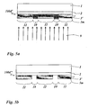
- a multilayer body 100 is shown in which a functional layer 2, a replication layer 3, a structured first layer 3m of aluminum and two differently colored, transparent photoresist layers 12a, 12b are arranged in register with the first layer 3m on a carrier foil 1.
- the functional layer 2 is a layer which primarily serves to increase the mechanical and chemical stability of the multilayer body, but which can also be formed in a known manner to produce optical effects, it also being possible to provide the layer of several partial layers train. It may also be a layer which is formed from wax or which is formed as a release layer. However, it can also be provided to dispense with this layer and to arrange the replication layer 3 directly on the carrier film 1. It can further be provided to form the carrier film 1 itself as a replication layer.
- the multilayer body 100 can be a section of a transfer film, for example a hot stamping foil, which can be applied to a substrate by means of an adhesive layer (not shown here).
- the adhesive layer may be a hotmelt adhesive which melts upon thermal exposure and permanently bonds the multilayer body to the surface of the substrate.
- the carrier film 1 may be formed as a mechanically and thermally stable film made of PET.
- first regions 4 with diffractive relief structures and second regions, the planar regions 6 are present.
- the first layer 3m arranged on the replication layer 3 has demetallized areas 10d, which are arranged congruently with the first areas 4. In the regions 10d, the multilayer body 100 appears transparent or partially transparent.
- Fig. 2 to 8 now show the manufacturing stages of the multi-layer body 100. Same elements as in Fig. 1 are designated with the same positions.
- Fig. 2 shows a multi-layer body 100a, in which on the carrier film 1, the functional layer 2 and the replication layer 3 are arranged.
- the replication layer 3 is superficially structured by known methods.
- a thermoplastic replication varnish is applied by printing, spraying or laking, and a relief structure is molded into the replication varnish by means of a heated stamp or a heated replicating roller.
- the replication layer 3 can also be a UV-curable replication lacquer, which is structured, for example, by a replication roller.
- the structuring can also be produced by UV irradiation through an exposure mask. That way the areas can be 4 and 6 may be molded into the replication layer 3. In the region 4, it may by the optically active areas of a hologram or a Kinegram ® -Sicherheitsmerkmals act, for example.
- Fig. 3 now shows a multi-layer body 100b, which consists of the multi-layer body 100a in Fig. 2 is formed by the first layer 3m is applied to the replication layer 3 with uniform area density relative to the plane spanned by the replication layer 3, for example by sputtering.
- the first layer 3m has a layer thickness of several 10 nm in this exemplary embodiment.
- the layer thickness of the first layer 3m may preferably be chosen so that the regions 4 and 6 have a low transmission, for example between 10% and 0.001%, ie an optical density between 1 and 5, preferably between 1.5 and 3.
- the optical Density of the first layer 3m, ie the negative decadic logarithm of the transmission, is therefore in the ranges 4 and 6 between 1 and 3.
- it can be provided to form the first layer 3m with an optical density between 1.5 and 2.5.
- the areas 4 and 6 therefore appear opaque to the eye of the observer.
- the first layer 3m in a layer thickness at which the first layer 3m when applied to a planar surface, ie as in the regions 6, is substantially opaque and has an optical density of greater than 2.
- Investigations have shown that the change in the effective optical thickness of the first layer 3m caused by the diffractive relief structure is approximately proportional to the vapor-deposited layer thickness and thus is approximately proportional to the optical density. Since the optical density represents the negative logarithm of the transmission, the transmission difference between the regions 4 and 6 is increased disproportionately by increasing the surface area of material of the first layer 3m.
- the optical densities of the first layer 3m in the regions 4 and 6 are different in that they are reduced in the regions 4 compared to the regions 6. This is due to the surface enlargement in the regions 4 because of the non-zero depth-to-widths Ratio of the structural elements and thereby reduced thickness of the first layer 3m.
- the dimensionless depth-to-width ratio as well as the spatial frequency are characteristic features for the surface enlargement of preferably periodic structures. Such a structure forms “mountains” and “valleys” in a periodic sequence. Depth is here the distance between "mountain” and “valley”, as width the distance between two "mountains”.
- optical density reduction When forming areas with reduced optical density, it is important to know the individual parameters in their dependencies and to choose appropriate.
- the degree of optical density reduction can be vary depending on the ground, the lighting, etc.
- An important role is played by the absorption of light in the first layer. For example, chromium and copper may reflect much less.
- silver and gold have a high maximum reflectance R Max and require a relatively small depth to width ratio of a relief structure to reduce the optical density of the first layer the above example for the formation of transparency.
- aluminum also has a high maximum reflectance R Max , but requires a higher depth-to-width ratio of the relief structure.
- it may be provided to form the first layer of silver or gold. But it can also be provided to form the first layer of other metals, metal alloys or functional layer materials.
- Table 2 now shows the calculation results obtained from strict diffraction calculations for relief structures formed as linear, sinusoidal gratings with a grid spacing of 350 nm with different depth-to-width ratios.
- the degree of transparency or the reflectance of the metal layer is wavelength-dependent. This effect is especially good for TEpolarized light.
- the degree of transparency or transmission decreases when the angle of incidence of the light differs from the normal angle of incidence, i. the degree of transparency decreases when the light is not incident vertically.
- the first layer 3m can be made transparent or less opaque than in the specular areas 6 only in a limited incidence cone of the light. It can therefore be provided that the first layer 3m is formed opaque with oblique illumination, whereby this effect is also useful for the selective formation of further partially formed layers.
- the change in the optical density is also influenced by the spatial frequency of the relief structure. It has further been shown that a change in the transmission behavior of a first layer applied to a relief structure can be achieved if the product of spatial frequency and relief depth in a first region of the relief structure is greater than the product of spatial frequency and relief depth in a second region of the relief structure ,
- the first relief structure is a relief structure with a stochastic profile, for example a matt structure, correlation length, roughness depth and statistical distribution of the profile can be typical parameters which influence the transmission.
- Fig. 4 shows a multi-layer body 100c formed from the in Fig. 3 This may be an organic layer, which is applied in liquid form by conventional coating methods, such as gravure printing. It can also be provided that the photosensitive layer 8 is vapor-deposited or laminated as a dry film.
- the photosensitive layer 8 may be, for example, a positive photoresist such as AZ 1512, or AZ P4620 from Clariant or S1822 from Shipley, act, which in a surface density of 0.1 g / m 2 to 50g / m 2 first layer 3m is applied.
- the layer thickness depends on the desired resolution and the process. For example, lift-off processes require thicker layers with a layer thickness> 1 ⁇ m, corresponding to a surface density of approx. 1 g / m 2 .
- Preferred basis weights are in the range of 0.2 g / m 2 to 10 g / m 2 .
- an order is provided here over the entire area. However, an order may also be provided in partial areas, for example in areas which are arranged outside the above-mentioned areas 4 and 6. These may be areas that need only be relatively coarsely registered in the register for design, such as decorative pictorial representations, such as those shown in FIG. Random patterns or patterns formed from repeated images or texts.
- Fig. 5 now shows a multilayer body 100d, which by the exposure of the multi-layer body 100c in Fig. 4 is formed through the carrier film 1 therethrough.
- UV light 9 may be provided for exposure. Since, as described above, the regions 4 of the first layer 3m provided with diffractive structures having a depth-to-width ratio greater than zero have a lower optical density than the reflecting regions 6 of the first layer 3m, the UV Irradiation in the photosensitive layer 8 generates more exposed areas 10, which differ from less exposed areas 11 in their chemical properties.
- Wavelength and polarization of the light as well as the angle of incidence of the light are illumination parameters that allow to highlight and selectively process relief structures.
- Regions 10 and 11 may differ, for example, in their solubility in solvents.
- the photosensitive layer 8 can be "developed” after exposure to UV light, as described hereinafter Fig. 6 is shown. In the "development” of the photosensitive layer 8, the removal of areas 10 or 11 is achieved in the photosensitive layer 8.
- a depth-to-width ratio> 0.3 is usually provided in the regions 4 for forming a transparency visible to the human eye, it has surprisingly been found that the depth-to-width ratio sufficient for the development of the photosensitive layer 8 is sufficient. Ratio can be much smaller. It is also not necessary to make the first layer 3m so thin that the regions 4 appear transparent when viewed visually. The vapor-deposited carrier film can therefore be made opaque be, because the reduced transparency can be compensated by an increased exposure dose of the photosensitive layer 8. It is further to be considered that the exposure of the photosensitive layer 8 is typically provided in the near UV region, so that the visual viewing impression is not critical for the evaluation of the optical density.
- a modified embodiment is shown in the multi-layer body 100d 'in Fig. 5a is the in Fig. 5 shown photosensitive layer 8 is not provided. Instead, a replication layer 3 'is provided, which is a photosensitive washcoat layer colored with a thermochromic substance.
- the multilayer body 100d ' is exposed from below through the first layer 3m, whereby in the more exposed areas 10 the replication layer 3' is changed so that it can be washed out.
- Fig. 5b shows now a multi-layer body 100d "which results from the multi-layer body 100d 'after the washing process.”
- the first layer 3m has been simultaneously removed during the washing process with the replication layer 3'
- the structured replication layer 3 ' forms a first partially formed thermochromic Functional layer, the first layer 3m forms in the perfect register to a first further partially formed layer of aluminum.
- Fig. 6 shows the "unwrapped" multilayer body 100e formed from the multilayer body 100d by the action of a solvent applied on the surface of the exposed photosensitive layer 8.
- regions 10e are now formed in which the photosensitive layer 8 is removed. These are the areas 10e around the in Fig. 3 described regions 4 with a depth-to-width ratio greater than zero of the structural elements.
- the photosensitive layer 8 is obtained, because it is the in Fig. 3 described areas 6, in which the structural elements have a depth-to-width ratio equal to zero.
- a transparent positive photoresist colored with blue color pigment is used as the photosensitive layer 8, a partially formed transparent blue functional layer forms in the register for the relief structure.
- the photosensitive layer 8 is thus formed of a positive photoresist.
- the exposed areas are soluble in the developer.
- the unexposed areas are soluble in the developer, as described below in US Pat Fig. 9 to 12 illustrated embodiment.
- the first layer 3m is removed in the regions 10e which are not protected from the attack of the etchant by the developed photosensitive layer 8 as an etching mask.
- the etchant may be, for example, an acid or alkali. In this way, they are also in Fig. 1 formed regions 10d formed.
- the structured photosensitive layer 8 forms the first partially formed transparent blue functional layer, the first layer 3m, after the etching in perfect register, forms a first further partially formed layer of aluminum.
- the first layer 3m can be structured in register without additional technological effort.
- no complex precautions are to be taken, such as during application an etching mask by mask exposure or pressure.
- tolerances> 0.2 mm are common.
- tolerances in the ⁇ m range up to the nm range are possible with the method according to the invention, ie tolerances which are determined only by the replication method chosen for structuring the replication layer and the origination.
- the first layer 3m may be provided to form the first layer 3m as a sequence of different metals and to use the differences in the physical and / or chemical properties of the metallic sublayers.
- it may be provided to deposit aluminum as the first metallic sub-layer, which has a high reflection and therefore makes it possible to clearly emerge from the carrier side when the multilayer body is viewed.
- Chromium may be deposited as the second metallic sublayer, which has a high chemical resistance to various etchants. The etching of the first layer 3m can now be provided in two stages.
- Such multilayer systems allow greater flexibility in the selection of photoresist, etchant, and first layer materials used in the fabrication process.
- Fig. 8 shows the optional option, after the in Fig. 7 illustrated production step communiquérakeln a layer 8a of transparent, luminescent pigments containing ink in the first regions 10d.
- Fig. 8 is a Multilayer body 100g, formed from the carrier film 1, the functional layer 2, the replication layer 3, the structured first layer 3m of aluminum as a first further partially formed layer, the structured transparent blue photosensitive layer 8 as a first partially formed functional layer and partially formed further layer 8a of transparent luminescent ink as a second partially shaped functional layer.
- a second embodiment of a multi-layer body 100e ' is shown in which, instead of the photosensitive layer 8 of positive photoresist (according to FIG Figures 5 . 6 . 6 and 8th ) a photosensitive layer 8 of negative photoresist was used.
- a multilayer body 100e ' has areas 10e' in which the unexposed photosensitive layer 8 has been removed by development.
- the areas 10e ' are opaque areas of the first layer 3m.
- regions 11 ' the exposed photosensitive layer 8 is not removed; these are more transmissive regions of the first layer 3m, ie regions with a lower optical density than the regions 10e'.
- Fig. 10 is a multi-layer body 100f 'shown by removing the first layer 3m by an etching process from the multi-layer body 100e' ( Fig. 9 ) is formed.
- the developed photosensitive layer 8 is provided as an etching mask, which in the areas 10e '( Fig. 9 ), so that the etchant there can decompose the first layer 3m. In this way, regions 10d 'are formed which no longer have a first layer 3m.
- the partially shaped layer 8 can be used as an opaque, black-colored lacquer layer be formed and form the partially shaped functional layer, while the partially formed first layer 3m forms the further layer.
- a thin-layer sequence having color effects can be formed, for example, from three thin layers with a high-low-high-index profile For example, it appears less conspicuous in comparison with metallic reflective layers, which is advantageous, for example, when forming patterns on passports or ID cards, for example, the patterns may appear to the viewer as transparent green or red.
- Fig. 12 now shows a multi-layer body 100f "'formed from the multi-layer body 100f" ( Fig. 11 ) after removal of the residual photosensitive layer 8.
- This may be a conventional "lift-off” process.
- the dielectric layer 3p applied thereto in the previous step is removed again.
- adjacent areas with the dielectric layer 3p and the first layer 3m of aluminum are formed on the multilayer body 100f '", which differ from each other, for example, in their optical refractive index and / or their electrical conductivity.
- a transparent, UV-curable liquid crystal can be applied as a virtually negative photoresist and exposed through the carrier layer 1.
- the less exposed portions of the photoresist layer are above the partially formed first layer 3m and are removed.
- etchant may be provided which does not attack the dielectric layer 3p applied in the other regions. However, it can also be provided to leave the etchant active only until the first layer 3m is no longer recognizable from the visual impression.
- Fig. 13 now shows a multi-layer body 100 ', which consists of the multi-layer body 100f "' ( Fig. 12 ) by adding the in Fig. 1 illustrated photoresist layers 12a, 12b is formed.
- the multilayer body 100 ' is like that in FIG Fig. 1 shown multilayer body 100 has been prepared by using the same replication layer 3. It is thus possible with the method according to the invention to produce differently configured multilayer bodies starting from a uniform layout.
- the method according to the invention can be continued without loss of quality in order to structure further layers in register.
- further optical effects such as total reflection, polarization and spectral transmittance of the previously applied layers to form regions of different optical density in order to form register-accurate exposure masks.
- Fig. 14 shows in a schematic sectional view of an enlarged section of a layer structure according to FIG. 3 ,
- the replication layer 3 has a first relief structure 5h with a high depth-to-width ratio> 0.3 in the area 5 and no relief structure or a flat area in the area 6.
- Arrows 3s indicate the application direction of the first layer 3m, which is applied here by sputtering.
- the first layer 3m is formed in the planar region 6n with the nominal thickness t 0 and formed in the region of the first relief structure 5h with the thickness t, which is smaller than the nominal thickness t 0 .
- the thickness t a is to be understood as an average value, since the thickness t is formed as a function of the angle of inclination of the surface of the first relief structure 5 h relative to the horizontal. This angle of inclination can be mathematically described by the first derivation of the function of the first relief structure 5h.
- the first layer 3m with the nominal thickness t 0 is deposited, if the amount of the inclination angle is greater than zero, the first layer 3m with the thickness t is deposited, that is nominal with a smaller thickness than the Thickness t 0 .
- Fig. 15 a shows in cross-section a carrier layer 1 made of PET, at least one functional layer 2 and a replication layer 3.
- a first kinematic relief structure is formed in the replication layer 3.
- the replication layer 3 is then completely coated with a first layer 3m made of silver, wherein different transmissive regions are formed in the first layer 3m in the register to the regions C and D.
- FIG. 15 (B) is on the layer composite according to Figure 15 (A) applied over the entire surface of a positive photoresist layer 12 and exposed through the support layer 1 therethrough. The more exposed or generally exposed areas C of the photoresist layer 12 are removed and the underlying first layer 3m is exposed in the area of the relief structure.
- the first layer 3m is removed in the regions C by etching, wherein the patterned photoresist layer 12 serves as an etching mask. After etching, only the patterned first layer 3m is present between the photoresist layer 12 and the replication layer.
- a dielectric reflection layer R of ZnS high refractive index or a thin film reflection layer stack with View angle-dependent interference color effect evaporated on the entire surface.
- the photoresist layer 12 may optionally be removed beforehand.
- FIG. 15 (F) There is now a multi-layer body 100k which comprises a carrier layer 1, a functional layer 2, a replication layer 3, in the first region C a partially formed functional layer in the form of the patterned red photoresist layer 12 'and a further partially formed layer in the form of the dielectric structured reflection layer R in the register to the photoresist layer 12 ', adjacent to a reflecting surface of silver formed by the partially formed first layer 3m in the planar second regions D.
- Figure 15 (G) shows a multilayer body 100k ', which according to a method according to the FIGS. 15 (A) to 15 (F) is formed, in the top view.
- a kinematic design element D exhibiting a pumping effect upon tilting was formed of a plurality of fine lines having a line width of 20 ⁇ m each.
- the lines themselves correspond to the first areas C with relief structure, while the areas between the lines correspond to the second areas D without relief structure.
- the lines thus show the kinematic effect due to the relief structure and the dielectric layer R and are also deposited with red color due to the photoresist layer 12 '.
- FIGS. 16 (A) to (C) show a further embodiment of the first method in sectional view.
- Figure 16 (A) shows a carrier layer 1 made of PET, a functional layer 2 and a replication layer 3, in which in the first regions C a relief structure was imprinted. In the second regions D, there is no relief structure, the replication layer 3 is flat here. Thereupon, a first layer 3m of gold is sputtered over the entire surface and opaque, with a higher transmission for UV radiation in the first regions C than in the regions D.
- a multilayer body 100m is present, which has a carrier layer 1, a functional layer 2, a replication layer 3, a partially formed functional layer in the form of a blue photoresist layer 12 and in perfect register a further partially formed layer in the form of the first layer 3m of gold , Will the multi-layer body Viewed 100 m from the side of the carrier layer 1, the first region C shows a golden line pattern superposed with a diffractive relief structure which produces an optically variable effect, in particular a holographic effect. Seen from the other side, the multi-layer body 100m shows a completely different appearance. Thus, the observer only sees a filigree opaque blue line pattern from the side of the photoresist layer 12 in the areas C. The golden line pattern is perfectly covered with it and therefore not visible. In areas D, the multi-layer body 100m is transparent.
- FIGS. 17 (A) to 17 (H) show the sequence of a complex first method in the sectional view.
- Figure 17 (A) shows a carrier layer 1, a functional layer 2 and a replication layer 3, in which three different relief structures were imprinted.
- a first relief structure was formed in regions A
- a second relief structure was formed in regions B
- a third kinematic relief structure was formed in regions C
- no relief structure was formed in region D.
- the first and the second relief structure are high-frequency lattice structures with different aspect ratios.
- the replication layer 3 according to Figure 17 (B) a first layer 3m of aluminum over the entire surface and opaque sputtered, resulting in the areas A higher transmission for UV radiation than in the areas B, in the areas B gives a higher transimission for UV radiation than in the areas C and areas C gives a higher transmission for UV radiation than in the areas D.
- a positive photoresist layer 12 is applied over the entire surface and exposed through the first layer 3 m through, wherein the areas A with the first relief structure are exposed the most and can be removed thereafter.
- Figure 17 (D) shows the photoresist layer 12 after patterning and after removal of the first layer 3m in the regions A by etching, the patterned photoresist 12 serving as an etching mask.
- the first layer 3m is thus only in the areas B, C and D.
- FIG. 17 (E) shows the layer structure at this stage after patterning of the negative photoresist layer 12 '.
- the exposed first layer 3m is now removed in areas B by etching.
- the result shows Figure 17 (H) ,
- a multilayer body 100n with a carrier layer 1, a functional layer 2, a Replication layer 3, a partially shaped blue functional layer in the form of the negative photoresist layer 12 ', another partially shaped layer in the form of the first layer 3m, which acts on the one hand as a mirror surface in the areas D and on the other hand with the kinematic effect in the area C superimposed.
- the further positive photoresist layer 12 is optionally removed and an adhesive layer is applied over the whole area, but if a colored positive photoresist layer 12" is used, it can also remain on the multilayer body.
- FIGS. 18 (A) to 18 (H) show in a sectional view schematically another first method for producing a filigree print pattern of two different colors in perfect register with each other.
- Figure 18 (A) shows a carrier layer 1, a functional layer 2 and a replication layer 3, in which two different relief structures were imprinted.
- a first relief structure was formed in the regions A, in the regions B a second relief structure was formed, while in the region D no relief structure was formed.
- the first and the second relief structure are high-frequency lattice structures with different aspect ratios.
- a first layer 3m made of aluminum is sputtered over the entire surface and opaque, resulting in a higher transmission for UV radiation in areas A than in areas B and in areas B gives a higher transmission for üv-Sirahlung than in the areas D.
- the positive photoresist layer 12 is completely removed and the first layer 3m is also completely removed by etching.
- a red-colored further negative photoresist layer 12 "' is then applied over the entire surface and exposed through the carrier layer 1, wherein hardening takes place in areas B. In the remaining areas, the red-colored further negative photoresist layer 12 '"is removed Figure 18 (G) ,
- FIG. 18 (H) where a multilayer body 100p is formed with a carrier layer 1, a functional layer 2, a partially formed functional layer in the form of the blue negative photoresist layer 12 'and a further partially formed layer in the form of the further red negative photoresist layer 12'' Blue layer 12 ', 12 "' are positioned in perfect register with each other.
- FIG. 18 (K) shows one according to a method according to the FIGS. 18 (A) to (H) formed multilayer body 100p 'in plan view.
- Blue lines formed from the negative photoresist layer 12 'and red lines formed from the further photoresist layer 12 "', which together form a colored filigree security design element in front of a transparent background, are indicated by a dashed line, an elliptical area being indicated.
- the virtual dash-dot line intersects a colored line of the design element, the color changes from red to blue, and the line is just continued without any offset.
- "Such design elements are extremely difficult to imitate. Such a register-accurate arrangement of different colors along a line has hitherto not been achieved with known methods, but design elements produced by the method according to the invention can also have adjacent color lines or intersecting color lines.
- Figure 18 (M) shows another according to a method according to the FIGS. 18 (A) to (H) Blue lines formed from the negative photoresist layer 12 'and red lines formed from the further photoresist layer 12 "', which together form a colored round security design element in front of a transparent background, are recognizable.
- the extension of the red lines shows a cross shape. In all the places of the circumference of the cross, the color within the course of the line changes directly from red to blue, the line being continued without any offset.
- Such design elements are also extremely difficult to imitate.
- such a security design element may be formed instead of the blue lines with a reflective metal layer, instead of the red lines with a luminescent layer or liquid crystal layer, etc., as well as many others.
- a different color impression can be generated by the front and the back of the multilayer body on such a security element.
- FIG. 19 shows a further sectional view through a multi-layer body 100r according to the invention.
- a carrier layer 1 and a replication layer 3 into which a first relief structure is introduced in first regions A.
- a second area B In the second areas B, on the other hand, there is no relief structure.
- a green printing ink was doctored in, which forms a structured first layer 3m ", which here is shown in exaggerated thickness.
- a transparent spacer layer 2 ' is formed and a red one on this colored positive photoresist layer 12 applied over the entire surface.
- the photoresist layer 12 is exposed through the carrier layer 1 and the first layer 3m ", which functions as an exposure mask, followed by removal of the photoresist layer 12 in the regions B.
- the result is a partially formed functional layer in the form of the green ink a further partially formed layer is exactly deposited in the form of the red structured photoresist layer 12. Due to the spacer layer 2 ', there are also optical overlay effects such as viewing angle-dependent moiré effects or local shadowing effects.
- a red-colored positive photoresist layer 12 is applied over the entire surface.
- the photoresist layer 12 is exposed through the carrier layer 1 and the first layer 3m ", which functions as an exposure mask, followed by removal of the photoresist layer 12 in the regions B.
- the result is a partially formed functional layer in the form of the green ink a further partially formed layer in the form of the red patterned photoresist layer 12 is exactly deposited.
- an adhesive layer 2 may be provided.
- FIGS. 20 (A) to (C) show in a sectional view schematically another first method. It is in accordance with Figure 20 (A) a carrier layer 1, a functional layer 2 and a Repiizier Anlagen 3 are provided, in which in first areas A a relief structure is introduced, while second areas D remain flat. On top of this, a first layer 3m of aluminum is sputtered over the whole area, which is transparent in the areas A and already opaque in the areas D.
- a yellow-colored transparent negative photoresist layer 12 is applied over the entire surface and exposed through the support layer 1 therethrough. Subsequently, the unexposed areas of the photoresist layer 12, ie in the areas D, are removed and the first layer 3m is exposed there.
- the multilayer body 100s has a carrier layer 1, a functional layer 2, a replication layer 3, a yellow photoresist layer 12 as a partially formed functional layer and, in the perfect register, a blue photoresist layer 12 'as a further partially formed layer in front of a transparent background.
- the transparent first layer 3m which is still present in the areas A, allows, when the multilayer body 100s is viewed from the side of the carrier layer 1, to recognize the relief structure without itself having a color effect.
- FIG. 21 shows a further multilayer body according to the invention, which was formed by the first method, with a carrier layer 1, a replication layer 3, a structured first layer 3m of aluminum, a transparent spacer layer 2 'and two differently colored photoresist layers 12, 12'.
- a transparent adhesive layer 2 is provided.
- FIGS. 22 (A) to 23 (B) show sectional views of security documents produced by the first method.
- Figure 22 (A) 1 shows a transparent identification card 1 'on which a transparent multi-layer body 100t has been bonded by means of the adhesive layer 2 "It is a transparent protective lacquer layer in the form of a functional layer 2, a replicate layer 3 of transparent lacquer with a first relief structure, a partially shaped first layer 3m in the form of an opaque aluminum layer, a further partially formed layer in the form of a transparent dielectric reflection layer of ZnS, and a partially shaped functional layer 12 in the form of an opaque green printing ink
- the functional layer 12 is in perfect register with the further partially formed layers 3m, 3m '. and the first relief structure is formed in the replication layer 3.
- the viewer thus shows through the functional layer 2 a line-shaped holographic representation, which on the one hand is deposited with fine aluminum lines and on the other hand with a transparent ZnS layer and green color is deposited. Viewed from the other side, the viewer shows through the ID card 1 'through only a filigree green print of fine lines.
- Figure 22 (B) 1 shows a transparent identification card 1 'on which a transparent multi-layer body 100t' has been bonded by means of the adhesive layer 2
- It is a transparent protective lacquer layer in the form of a functional layer 2, a replication layer 3 of transparent lacquer with a first relief structure, a partially shaped first layer 3m in the form of an opaque aluminum layer, a further partially formed layer in the form of a transparent dielectric reflection layer of ZnS, and a partially shaped functional layer 12 in the form of an opaque green printing ink
- the functional layer 12 is in perfect register with the further partially formed layers 3m, 3m
- the viewer is thus presented with a filigree green printed image of fine lines through the functional layer 2. Seen from the other side, the viewer sees through the identification card 1 'a linear line Holographic representation, which is deposited on the one hand with fine aluminum lines and on the other hand deposited with a transparent ZnS layer and green color.
- FIG. 23 (A) shows a transparent ID card 1 ', on which a transparent multi-layer body 100t "was glued by means of a transparent adhesive layer 2". It is a transparent protective lacquer layer in the form of a functional layer 2, a replicate layer 3 of transparent lacquer with a first relief structure, a partially shaped first layer 3m in the form of an opaque aluminum layer, the adhesive layer 2 ", which acts as a spacer layer here, another partially shaped A layer in the form of a transparent red photoresist layer 12 and a partially formed functional layer 12 'in the form of an opaque green printing ink The red photoresist layer 12 is seen partly coincident with the partially formed first layer 3m and partially offset relative to the plane of the ID card 1' The partially formed Functional layer 12 'is offset from the first layer 3m.
- the observer thus shows through the functional layer 2 through a filigree decorative image of fine green, red and metallic lines, the metallic lines show a holographic effect due to the first relief structure.
- the viewer also shows through the ID card 1 'through a delicate decor image of fine green, red and metallic lines, the metallic lines show a holographic effect due to the first relief structure.
- some of the metallic lines are overlaid by the transparent red photoresist layer 12. If the multi-layer body 100t "by a forger detached from the ID card 1 'to manipulate personal data on the surface of the ID card 1' remain the red and the green layer 12, 12 'on the ID card 1', while the other layers 2 ", 3m, 3, 2 detach.
- the detached layer stack After manipulating the data, the detached layer stack must again be applied to the ID card 1 'in such a way that the filigree decor image results. Due to the fine lines, this is almost hopeless and deviations from the original situation remain recognizable.
- the ID card 1 ' is protected by the multi-layer body 100t "particularly effective against counterfeiting attempts.
- FIG. 23 (B) shows a transparent ID card 1 ', on which a transparent multi-layer body 100t "' was glued by means of a transparent adhesive layer 2". It is a transparent protective lacquer layer in the form of a functional layer 2, a replication layer 3 of transparent lacquer with a first relief structure, a partially shaped first layer 3m as a functional layer in the form of a transparent red photoresist layer 12, the adhesive layer 2 ", which acts as a spacer layer, and another partially formed layer in the form of an opaque green Photoresist layer 12 'present.
- the red photoresist layer 12 is formed perpendicular to the plane of the ID card 1 'congruent to the first relief structure and partially congruent with the partially formed green photoresist layer 12' arranged.
- the viewer thus shows through the functional layer 2 through a delicate decor image of fine transparent red and opaque black lines.
- the viewer shows through the ID card 1 'through a delicate decor image of fine opaque green and transparent red lines.
- the detached layer stack After manipulating the data, the detached layer stack must again be applied to the ID card 1 'in such a way that the filigree decor image results. Due to the fine lines, this is almost hopeless and deviations from the original situation remain recognizable. Identity card 1 'is also particularly effectively protected from counterfeiting attempts by multilayer body 100t "'.
- FIGS. 24 (A) to (E) show in a sectional view schematically a second method for producing a filigree print pattern of two different colors in perfect register with each other.
- Figure 24 (A) shows a transparent support layer 1 made of PET, on one side of a red-colored negative photoresist layer 12 has been applied over the entire surface.
- the negative photoresist layer 12 is then pattern-exposed through a mask 200 having radiation-transmissive openings 200a (the arrows indicate the direction of irradiation). After removal of the mask, the unexposed areas of the photoresist layer 12 are removed, while the exposed areas remain on the carrier layer 1 and form a red line pattern.
- Figure 24 (B) shows a transparent support layer 1 made of PET, on one side of a red-colored negative photoresist layer 12 has been applied over the entire surface.
- the negative photoresist layer 12 is then pattern-exposed through a mask 200 having radiation-transmissive openings 200a (the arrows indicate the direction of irradiation). After removal of the mask, the unexposed areas of the photoresist layer 12 are removed, while the exposed areas remain on the carrier layer 1 and form a red line pattern.
- Figure 24 (D) shows a security document formed with the thus formed 'multi-layer body, in which the formed multi-layer body 100v is shown glued to a transparent ID card 1'.
- the multi-layer body 100v comprises the transparent carrier layer 1, the red photoresist layer 12 functioning as a partially formed functional layer, in perfect registration the green photoresist layer 12 'present as a further partially formed layer and a transparent adhesive layer 2 " seen from a filigree red line pattern and from the ID card 1 'from a filigree green line pattern.
- Figure 24 (E) shows a security document, which is formed with the inclusive spacer layer formed multilayer body and at which the formed multi-layer body 100v 'is shown glued to a transparent ID card 1'.
- the multilayer body 100v ' comprises the transparent carrier layer 1, the red photoresist layer 12 acting as a partially formed functional layer, the transparent spacer layer 2' and in perfect register with the red photoresist layer 12 the green photoresist layer 12 'present as a further partially formed layer and a transparent adhesive layer 2 ".
- the security document shows a viewer from the carrier layer 1 from a filigree red line pattern and viewed from the ID card 1 'from a filigree green line pattern, depending on the thickness of the spacer layer 2' when tilting the security document, the other color and / or optical Show overlay effects.
Claims (15)
- Procédé servant à fabriquer un corps multicouche (100v) avec au moins une couche fonctionnelle partiellement formée dans le registre, par rapport à une autre couche partiellement formée, sachant qu'une première couche se présentant sous la forme d'une première couche de peinture de résine photosensible (12) est formée sur une couche de support (1) et est partiellement éclairée, que la première couche éclairée est développée et structurée, et qu'immédiatement après la couche fonctionnelle partiellement formée au moins au nombre de une et/ou l'autre couche partiellement formée, sont formées en utilisant la première couche structurée comme une couche de masque,
caractérisé en ce que
la couche fonctionnelle partiellement formée au moins au nombre de une ou l'autre couche partiellement formée au moins au nombre de une sont formées en ce qu'on applique une deuxième couche de peinture de résine photosensible (12') positive ou négative mélangée avec un colorant, en ce que la deuxième couche de peinture de résine photosensible (12') est éclairée à travers la première couche structurée, et en ce qu'une structuration de la deuxième couche de peinture de résine photosensible (12') éclairée est effectuée. - Procédé selon la revendication 1,
caractérisé en ce que
la première ou la deuxième couche de peinture de résine photosensible (12, 12') constituent la couche fonctionnelle partiellement formée au moins au nombre de une. - Procédé selon l'une quelconque des revendications 1 ou 2,
caractérisé en ce que
la couche de support (1) est immédiatement après réalisée partiellement en diffusant un colorant sous la forme d'une couche fonctionnelle partiellement formée ou sous la forme d'une autre couche partiellement formée, sachant qu'au moins la première et/ou la deuxième couche de peinture de résine photosensible (12, 12') font office de barrière de diffusion. - Procédé selon l'une quelconque des revendications 1 à 3,
caractérisé en ce que
un matériau est introduit par raclage dans des zones dégagées de la couche de support (1), lesquelles sont, vu de manière perpendiculaire par rapport au plan de la couche de support (1), entourées par une couche fonctionnelle partiellement formée ou par une autre couche partiellement formée, et en ce qu'au moins une autre couche fonctionnelle partiellement formée ou une autre couche partiellement formée sont formées. - Procédé selon l'une quelconque des revendications 1 à 4,
caractérisé en ce que
l'autre couche partiellement formée au moins au nombre de une est formée par la première couche (3m) et/ou au moins par une couche de peinture de résine photosensible (12, 12', 12", 12"') colorée positive ou négative et/ou par au moins une couche à variation optique présentant un effet optique différent selon l'angle de vue et/ou par au moins une couche réfléchissante métallique et/ou par au moins une couche réfléchissante (3m') diélectrique. - Procédé selon l'une quelconque des revendications 1 à 5,
caractérisé en ce que
la première couche (3m) structurée est supprimée au moins en partie et est remplacée par la couche fonctionnelle partiellement formée au moins au nombre de une et/ou par l'autre couche partiellement formée au moins au nombre de une. - Procédé selon l'une quelconque des revendications 1 à 6,
caractérisé en ce que
la couche fonctionnelle partiellement formée au moins au nombre de une est, vu de manière perpendiculaire par rapport au plan de la couche de support (1), disposée de manière à alterner ou à une distance homogène par rapport à au moins une autre couche partiellement formée. - Procédé selon l'une quelconque des revendications 1 à 7,
caractérisé en ce que
au moins une première couche d'espacement (2') transparente est disposée entre la couche fonctionnelle partiellement formée au moins au nombre de une et l'autre couche partiellement formée au moins au nombre de une, en ce qu'au moins une deuxième couche d'espacement transparente est disposée entre au moins deux autres couches partiellement formées, et en ce que la première et/ou la deuxième couche d'espacement sont réalisées localement avec au moins deux épaisseurs de couche différentes. - Corps multicouche, obtenu selon la revendication 1 ou selon la revendication 1, en lien avec l'une quelconque des revendications associées 2 à 8, comprenant au moins une couche fonctionnelle partiellement formée dans le registre par rapport au moins à une autre couche partiellement formée, sachant qu'une première couche se présentant sous la forme d'une première couche de peinture de résine photosensible (12) est structurée sur une couche de support (1) de manière à présenter une forme de motif, et en ce que la couche fonctionnelle partiellement formée au moins au nombre de une et/ou l'autre couche partiellement formée au moins au nombre de une sont réalisées en utilisant la première couche structurée en tant qu'une couche de masque,
caractérisé en ce que
la couche fonctionnelle partiellement formée au moins au nombre de une et/ou l'autre couche partiellement formée au moins au nombre de une est une deuxième couche de peinture de résine photosensible (12') positive ou négative mélangée à un colorant. - Corps multicouche selon la revendication 9, caractérisé en ce que
la couche fonctionnelle partiellement formée au moins au nombre de une et l'autre couche partiellement formée au moins au nombre de une se complètent mutuellement pour former une représentation décorative et/ou géométrique informative, alphanumérique, imagée, graphique ou colorée figurative. - Corps multicouche selon l'une quelconque des revendications 9 ou 10,
caractérisé en ce que
au moins la couche fonctionnelle partiellement formée au moins au nombre de une et/ou au moins l'autre couche partiellement formée au moins au nombre de une sont réalisées sous la forme au moins d'une ligne présentant une largeur de ligne comprise dans la plage < 50 µm, en particulier comprise dans la plage allant de 0,5 à 10 µm, et/ou sont réalisées sous la forme au moins d'un pixel présentant un diamètre de pixel compris dans la plage < 50 µm, en particulier compris dans la plage allant de 0,5 à 10 µm. - Corps multicouche selon l'une quelconque des revendications 9 à 11,
caractérisé en ce que
la couche fonctionnelle partiellement formée au moins au nombre de une est une couche contenant un cristal liquide ou est formée par un empilement de couches réfléchissantes à couches minces présentant un effet de couleurs par interférence dépendant de l'angle de vue, et en ce que l'autre couche partiellement formée au moins au nombre de une est la deuxième couche de peinture de résine photosensible, ou inversement. - Corps multicouche selon l'une quelconque des revendications 9 à 11,
caractérisé en ce que
la couche fonctionnelle partiellement formée au moins au nombre de une est la première couche de peinture de résine photosensible, et en ce que l'autre couche partiellement formée au moins au nombre de une est la deuxième couche de peinture de résine photosensible mélangée à un colorant, sachant que la première et la deuxième couche de peinture de résine photosensible sont colorées de manière différente. - Corps multicouche selon l'une quelconque des revendications 9 à 13,
caractérisé en ce que
la couche fonctionnelle partiellement formée au moins au nombre de une et l'autre couche partiellement formée au moins au nombre de une sont réalisées de manière à présenter une forme linéaire respectivement de telle manière que les lignes s'enchevêtrent les unes dans les autres sans décalage latéral. - Corps multicouche selon l'une quelconque des revendications 9 à 14,
caractérisé en ce que
une première couche d'espacement (2') transparente est réalisée entre la couche fonctionnelle partiellement formée au moins au nombre de une et l'autre couche partiellement formée au moins au nombre de une, en ce qu'une deuxième couche d'espacement transparente est réalisée entre au moins deux autres couches partiellement formées, et en ce que la couche fonctionnelle partiellement formée au moins au nombre de une et l'autre couche partiellement formée au moins au nombre de une sont réalisées de telle manière qu'apparaît au moins un effet optique de superposition, dépendant éventuellement de l'angle de vue.
Priority Applications (1)
| Application Number | Priority Date | Filing Date | Title |
|---|---|---|---|
| PL07786028T PL2049345T3 (pl) | 2006-08-09 | 2007-07-12 | Sposób wytwarzania korpusu wielowarstwowego oraz korpus wielowarstwowy |
Applications Claiming Priority (3)
| Application Number | Priority Date | Filing Date | Title |
|---|---|---|---|
| DE102006037431A DE102006037431A1 (de) | 2006-08-09 | 2006-08-09 | Verfahren zur Herstellung eines Mehrschichtkörpers sowie Mehrschichtkörper |
| DE102007002163 | 2007-01-15 | ||
| PCT/EP2007/006196 WO2008017362A2 (fr) | 2006-08-09 | 2007-07-12 | Procédé de fabrication d'un corps multicouche et corps multicouche |
Publications (2)
| Publication Number | Publication Date |
|---|---|
| EP2049345A2 EP2049345A2 (fr) | 2009-04-22 |
| EP2049345B1 true EP2049345B1 (fr) | 2013-06-19 |
Family
ID=39184699
Family Applications (1)
| Application Number | Title | Priority Date | Filing Date |
|---|---|---|---|
| EP07786028.6A Active EP2049345B1 (fr) | 2006-08-09 | 2007-07-12 | Procédé de fabrication d'un corps multicouche et corps multicouche |
Country Status (10)
| Country | Link |
|---|---|
| US (1) | US8367277B2 (fr) |
| EP (1) | EP2049345B1 (fr) |
| JP (1) | JP5124575B2 (fr) |
| KR (1) | KR101488539B1 (fr) |
| CN (1) | CN101516634B (fr) |
| CA (1) | CA2660231C (fr) |
| DE (1) | DE102006037431A1 (fr) |
| PL (1) | PL2049345T3 (fr) |
| UA (2) | UA97809C2 (fr) |
| WO (1) | WO2008017362A2 (fr) |
Cited By (5)
| Publication number | Priority date | Publication date | Assignee | Title |
|---|---|---|---|---|
| WO2016192858A1 (fr) | 2015-06-05 | 2016-12-08 | Giesecke & Devrient Gmbh | Procédé de fabrication d'un dispositif électronique et dispositif électronique obtenu au moyen dudit procédé |
| DE102015007233A1 (de) | 2015-06-05 | 2016-12-08 | Giesecke & Devrient Gmbh | Verfahren zum Herstellen eines Sicherheitselements, daraus erhältliches Sicherheitselement, Sicherheitspapier und Wertdokument |
| DE102015008971A1 (de) | 2015-07-10 | 2017-01-12 | Giesecke & Devrient Gmbh | Sicherheitselement und Datenträger |
| EP3275685B1 (fr) | 2016-07-25 | 2019-09-18 | Giesecke+Devrient Currency Technology GmbH | Papier de sécurité et document de valeur |
| WO2022174982A1 (fr) | 2021-02-19 | 2022-08-25 | Giesecke+Devrient Currency Technology Gmbh | Procédé de production d'un élément de sécurité comprenant des éléments de micro-imagerie |
Families Citing this family (79)
| Publication number | Priority date | Publication date | Assignee | Title |
|---|---|---|---|---|
| DE102005006277B4 (de) * | 2005-02-10 | 2007-09-20 | Ovd Kinegram Ag | Verfahren zur Herstellung eines Mehrschichtkörpers |
| DE102008005019B4 (de) * | 2008-01-17 | 2010-08-05 | Ovd Kinegram Ag | Folienelement sowie die Verwendung dieses Folienelements |
| US7920297B2 (en) * | 2008-02-18 | 2011-04-05 | Vistaprint Technologies Limited | System and method for printing using variable-density white ink under-printed layer |
| DE102008013073B4 (de) * | 2008-03-06 | 2011-02-03 | Leonhard Kurz Stiftung & Co. Kg | Verfahren zur Herstellung eines Folienelements und Folienelement |
| CA2656506A1 (fr) * | 2009-02-27 | 2010-08-27 | Bank Of Canada | Dispositif de verification des caracteristiques de securite |
| DE102009031386A1 (de) | 2009-07-01 | 2011-01-05 | Giesecke & Devrient Gmbh | Sicherheitselement und Herstellungsverfahren dafür |
| DE102009033762A1 (de) * | 2009-07-17 | 2011-01-27 | Leonhard Kurz Stiftung & Co. Kg | Verfahren zur Herstellung eines Mehrschichtkörpers sowie Mehrschichtkörper |
| DE102009052538A1 (de) | 2009-11-11 | 2011-05-12 | Giesecke & Devrient Gmbh | Herstellung eines mit gefärbten Mikrovertiefungen versehenen Sicherheitselementes |
| GB201003136D0 (en) | 2010-02-24 | 2010-04-14 | Rue De Int Ltd | Optically variable security device comprising a coloured cast cured hologram |
| CN106842394A (zh) * | 2010-06-25 | 2017-06-13 | 安德鲁·理查德·帕克 | 光学效应结构 |
| KR20120025156A (ko) * | 2010-09-07 | 2012-03-15 | 삼성전자주식회사 | 사출물의 외관 표면 처리 방법 |
| JP5594043B2 (ja) * | 2010-10-08 | 2014-09-24 | 凸版印刷株式会社 | 偽造防止構造体、及び偽造防止媒体 |
| US8797602B2 (en) * | 2011-03-23 | 2014-08-05 | Xerox Corporation | UV and IR specialty imaging methods and systems |
| US9064654B2 (en) | 2012-03-02 | 2015-06-23 | Microsoft Technology Licensing, Llc | Method of manufacturing an input device |
| US9706089B2 (en) | 2012-03-02 | 2017-07-11 | Microsoft Technology Licensing, Llc | Shifted lens camera for mobile computing devices |
| US9460029B2 (en) | 2012-03-02 | 2016-10-04 | Microsoft Technology Licensing, Llc | Pressure sensitive keys |
| US9870066B2 (en) | 2012-03-02 | 2018-01-16 | Microsoft Technology Licensing, Llc | Method of manufacturing an input device |
| US9075566B2 (en) | 2012-03-02 | 2015-07-07 | Microsoft Technoogy Licensing, LLC | Flexible hinge spine |
| US20130300590A1 (en) | 2012-05-14 | 2013-11-14 | Paul Henry Dietz | Audio Feedback |
| US8654030B1 (en) | 2012-10-16 | 2014-02-18 | Microsoft Corporation | Antenna placement |
| WO2014059618A1 (fr) * | 2012-10-17 | 2014-04-24 | Microsoft Corporation | Formation de graphique par ablation de matériau |
| EP2722191B1 (fr) * | 2012-10-18 | 2015-05-06 | Bundesdruckerei GmbH | Carte d'identité avec fonction physique inclonable |
| JP6476863B2 (ja) * | 2012-11-19 | 2019-03-06 | 凸版印刷株式会社 | 偽造防止構造体及びその製造方法 |
| US11907791B2 (en) * | 2013-01-18 | 2024-02-20 | Amatech Group Lijited | Smart cards with metal layer(s) and methods of manufacture |
| GB201301788D0 (en) * | 2013-02-01 | 2013-03-20 | Rue De Int Ltd | Security devices and methods of manufacture thereof |
| GB201301790D0 (en) * | 2013-02-01 | 2013-03-20 | Rue De Int Ltd | Security devices and methods of manufacture thereof |
| DE102013108666A1 (de) | 2013-08-09 | 2015-03-05 | Leonhard Kurz Stiftung & Co. Kg | Verfahren zur Herstellung eines Mehrschichtkörpers sowie Mehrschichtkörper |
| GB201316348D0 (en) * | 2013-09-13 | 2013-10-30 | Andrews & Wykeham Ltd | Security laminate/foil |
| CN104647934B (zh) * | 2013-11-21 | 2016-10-05 | 中钞特种防伪科技有限公司 | 一种光学防伪元件及其制作方法 |
| DE102013113283A1 (de) * | 2013-11-29 | 2015-06-03 | Leonhard Kurz Stiftung & Co. Kg | Mehrschichtkörper und Verfahren zu dessen Herstellung |
| DE102013021964A1 (de) * | 2013-12-20 | 2015-06-25 | Giesecke & Devrient Gmbh | Sicherheitsdokument sowie Verfahren zum Herstellen eines Sicherheitsdokuments |
| FR3020309B1 (fr) | 2014-04-29 | 2016-05-27 | Hologram Ind | Composant optique de securite a effet reflectif, fabrication d'un tel composant et document securise equipe d'un tel composant |
| CN105015216B (zh) * | 2014-04-29 | 2017-06-16 | 中钞特种防伪科技有限公司 | 一种光学防伪元件及制备光学防伪元件的方法 |
| DE102014106340B4 (de) * | 2014-05-07 | 2021-05-12 | Ovd Kinegram Ag | Mehrschichtkörper und Verfahren zu dessen Herstellung sowie Sicherheitsdokument |
| WO2015179639A1 (fr) * | 2014-05-22 | 2015-11-26 | Composecure, Llc | Cartes de transaction et d'identité ayant une certaine texture et une certaine coloration |
| EP2955029B1 (fr) * | 2014-06-13 | 2018-01-31 | Agfa-Gevaert | Matériaux pouvant être marqués au laser et documents |
| AU2015287440B2 (en) * | 2014-07-07 | 2020-04-23 | Security Fibres Uk Limited | Improvements in and relating to security documents |
| DE102014118365A1 (de) | 2014-12-10 | 2016-06-16 | Leonhard Kurz Stiftung & Co. Kg | Absorptionsmedium, Transferfolie, Sicherheitselement und Verfahren zum Individualisieren eines Sicherheitselements |
| AT516688A1 (de) * | 2014-12-15 | 2016-07-15 | Hueck Folien Gmbh | Sicherheitselement mit Farbkippeffekt und fluoreszierenden Merkmalen, Verfahren zu dessen Herstellung und dessen Verwendung |
| DE102015100280A1 (de) * | 2015-01-09 | 2016-07-14 | Ovd Kinegram Ag | Verfahren zur Herstellung von Sicherheitselementen sowie Sicherheitselemente |
| DE102015100520A1 (de) * | 2015-01-14 | 2016-07-28 | Leonhard Kurz Stiftung & Co. Kg | Mehrschichtkörper und Verfahren zu dessen Herstellung |
| FR3031697B1 (fr) * | 2015-01-16 | 2020-12-18 | Hologram Ind | Composant optique de securite. |
| WO2016125488A1 (fr) | 2015-02-03 | 2016-08-11 | 凸版印刷株式会社 | Support d'information optique |
| CA3151575A1 (fr) * | 2015-03-05 | 2016-09-09 | Magic Leap, Inc. | Fabrication amelioree pour systemes et composants de realite virtuelle et augmentee |
| DE102015104416A1 (de) * | 2015-03-24 | 2016-09-29 | Leonhard Kurz Stiftung & Co. Kg | Mehrschichtkörper und Verfahren zu dessen Herstellung |
| DE102015105285A1 (de) * | 2015-04-08 | 2016-10-13 | Kurz Typofol Gmbh | Verfahren zur Herstellung eines Dokuments sowie ein Dokument |
| DE102015106800B4 (de) * | 2015-04-30 | 2021-12-30 | Leonhard Kurz Stiftung & Co. Kg | Verfahren zum Herstellen eines Mehrschichtkörpers |
| US10036125B2 (en) | 2015-05-11 | 2018-07-31 | Nanotech Security Corp. | Security device |
| EP3306362B1 (fr) | 2015-06-02 | 2021-11-03 | Toppan Printing Co., Ltd. | Stratifié et son procédé de fabrication |
| WO2016206760A1 (fr) * | 2015-06-26 | 2016-12-29 | Fedrigoni Spa | Élément de sécurité ayant un motif et un effet holographique à double face |
| GB201513096D0 (en) | 2015-07-24 | 2015-09-09 | Rue De Int Ltd | Diffractive security device and method of manufacturing thereof |
| GB2545387A (en) | 2015-07-24 | 2017-06-21 | De La Rue Int Ltd | Security device and method of manufacturing thereof |
| CN105549213A (zh) * | 2016-03-10 | 2016-05-04 | 成都亚波长微纳科技研究院 | 二维平面仿真立体图案实现方法 |
| GB2549724B (en) * | 2016-04-26 | 2019-12-11 | De La Rue Int Ltd | Security devices and methods of manufacturing image patterns for security devices |
| EP3470896B1 (fr) | 2016-06-13 | 2021-02-17 | Dai Nippon Printing Co., Ltd. | Film de guidage de lumière, structure de prévention de falsification et article de prévention de falsification |
| US9861883B1 (en) | 2016-06-17 | 2018-01-09 | Mohawk Fine Papers Inc. | Secure substrate for scratch-off products |
| GB2551555B (en) * | 2016-06-22 | 2018-09-26 | De La Rue Int Ltd | Methods of manufacturing an image pattern for a security device |
| EP3576956A1 (fr) * | 2017-02-02 | 2019-12-11 | Fedrigoni S.p.A. | Double élément de sécurité métallique présentant un motif transparent |
| KR102648211B1 (ko) * | 2017-03-06 | 2024-03-14 | 쓰리엠 이노베이티브 프로퍼티즈 컴파니 | 고 콘트라스트 광학 필름 및 이를 포함하는 장치 |
| DE102017106721A1 (de) * | 2017-03-29 | 2018-10-04 | Leonhard Kurz Stiftung & Co. Kg | Verfahren zum Herstellen einer Mehrschichtfolie und eine Mehrschichtfolie sowie ein Sicherheitselement und ein Sicherheitsdokument |
| DE102017004037B4 (de) * | 2017-04-26 | 2019-06-27 | Mühlbauer Gmbh & Co. Kg | Sicherheitseinlage mit einer Vertiefung für ein Ausweisdokument und Verfahren zur Herstellung einer Sicherheitseinlage mit einer Vertiefung für ein Ausweisdokument |
| CN108873118B (zh) | 2017-05-16 | 2020-06-26 | 昇印光电(昆山)股份有限公司 | 光学元件、手机盖板及用于制备该光学元件的模具 |
| AT520011B1 (de) * | 2017-05-16 | 2019-10-15 | Hueck Folien Gmbh | Verfahren zur Herstellung eines Sicherheitselements sowie nach diesem Verfahren hergestelltes Sicherheitselement und dessen Verwendung |
| DE102017004784A1 (de) * | 2017-05-18 | 2018-11-22 | Giesecke+Devrient Currency Technology Gmbh | Verfahren zum Herstellen eines Sicherheitselements mit einem metallisierten Reliefbereich und zugehöriges Sicherheitselement |
| CN110691997B (zh) | 2017-05-22 | 2021-11-26 | 凸版印刷株式会社 | 信息记录体及个人证件 |
| DE102017006507A1 (de) * | 2017-07-10 | 2019-01-10 | Giesecke+Devrient Currency Technology Gmbh | Strukturelement |
| FR3089234B1 (fr) | 2018-11-29 | 2021-07-30 | Oberthur Fiduciaire Sas | Procédé de dépôt sous vide d’un revêtement sur la face frontale d'un support, support et document de sécurité correspondant |
| CN111746171B (zh) * | 2019-03-29 | 2021-06-15 | 中钞特种防伪科技有限公司 | 光学防伪元件及其制作方法 |
| CN111890817B (zh) * | 2019-05-05 | 2022-03-22 | 中钞特种防伪科技有限公司 | 多层镀层光学防伪元件及其制作方法 |
| CN112572014B (zh) * | 2019-09-30 | 2022-05-27 | 中钞特种防伪科技有限公司 | 光学防伪元件及防伪产品 |
| AT523393B1 (de) * | 2020-04-06 | 2021-08-15 | Hueck Folien Gmbh | Verfahren zur Herstellung eines Sicherheitselements mit einer farbigen Mikrostruktur |
| CN111487702B (zh) * | 2020-05-12 | 2021-02-12 | 深圳大学 | 轻金属膜粘附重金属胶体的光栅制作工艺 |
| DE102020005932A1 (de) | 2020-09-28 | 2022-03-31 | Giesecke+Devrient Currency Technology Gmbh | Optisch variables Sicherheitselement mit reflektivem Flächenbereich |
| CN112185968B (zh) * | 2020-09-30 | 2021-09-24 | 长江存储科技有限责任公司 | 一种半导体器件 |
| RU208267U1 (ru) * | 2021-07-01 | 2021-12-13 | Олег Умарович Айбазов | Банковская карта |
| DE102021003605A1 (de) | 2021-07-13 | 2023-01-19 | Giesecke+Devrient Mobile Security Gmbh | Ausweisdokument |
| DE102021124407A1 (de) | 2021-09-21 | 2023-03-23 | Leonhard Kurz Stiftung & Co. Kg | Thermochromes Sicherheitselement und Verfahren zur Herstellung eines thermochromen Sicherheitselements |
| WO2023148511A1 (fr) * | 2022-02-07 | 2023-08-10 | Sun Chemical Corporation | Réserve de démétallisation à base d'eau |
| CN114669979A (zh) * | 2022-05-30 | 2022-06-28 | 昆明理工大学 | 一种表面带花纹的铜银合金的制备方法 |
Family Cites Families (25)
| Publication number | Priority date | Publication date | Assignee | Title |
|---|---|---|---|---|
| US4094575A (en) * | 1976-04-30 | 1978-06-13 | Minnesota Mining And Manufacturing Company | Holographic article and process for making same |
| US4353952A (en) * | 1979-09-28 | 1982-10-12 | Hewlett-Packard Company | Transparent digitizer platen |
| GB2136352B (en) | 1982-12-03 | 1986-09-10 | Hollusions Limited | Hologram devices and methods of manufacture |
| JPS6079331A (ja) * | 1983-10-07 | 1985-05-07 | Citizen Watch Co Ltd | カラ−液晶表示装置の製造方法 |
| GB2189800B (en) | 1986-04-07 | 1990-03-14 | Michael Anthony West | Marking of articles |
| WO1989009989A1 (fr) * | 1988-04-12 | 1989-10-19 | Dia Nippon Insatsu Kabushiki Kaisha | Support d'enregistrement optique et procede de fabrication |
| US4971894A (en) | 1989-02-13 | 1990-11-20 | International Business Machines Corporation | Method and structure for preventing wet etchant penetration at the interface between a resist mask and an underlying metal layer |
| DE59204591D1 (de) | 1991-10-14 | 1996-01-18 | Landis & Gyr Tech Innovat | Sicherheitselement. |
| US5538753A (en) * | 1991-10-14 | 1996-07-23 | Landis & Gyr Betriebs Ag | Security element |
| JPH0679331A (ja) | 1992-08-31 | 1994-03-22 | Sumitomo Metal Ind Ltd | 熱間圧延における潤滑方法 |
| US5538757A (en) | 1993-04-30 | 1996-07-23 | Medical Materials Corporation | Method of making thermoplastic composite material |
| DE69632863T2 (de) * | 1995-08-01 | 2004-11-18 | Boris Iliich Belousov | Banddatenträger, verfahren und vorrichtung zum herstellen desselben |
| JPH10100573A (ja) | 1996-09-30 | 1998-04-21 | Toppan Printing Co Ltd | 偽造防止用紙及び偽造防止印刷物 |
| JPH1158581A (ja) | 1997-08-25 | 1999-03-02 | Toppan Printing Co Ltd | 偽造防止用積層材料 |
| US6761959B1 (en) | 1999-07-08 | 2004-07-13 | Flex Products, Inc. | Diffractive surfaces with color shifting backgrounds |
| DE10129939B4 (de) * | 2001-06-20 | 2006-06-22 | Ovd Kinegram Ag | Optisch variables Flächenmuster |
| WO2003052025A1 (fr) | 2001-12-18 | 2003-06-26 | Nanosolutions Gmbh | Liquide et procede d'impression de securite utilisant des nanoparticules |
| ES2279944T3 (es) * | 2002-05-14 | 2007-09-01 | LEONHARD KURZ GMBH & CO. KG | Elemento opticamente variable con serie de capas de pelicula delgada. |
| DE10318157A1 (de) * | 2003-04-17 | 2004-11-11 | Leonhard Kurz Gmbh & Co. Kg | Folie und optisches Sicherungselement |
| DE10318103A1 (de) * | 2003-04-22 | 2004-11-11 | Giesecke & Devrient Gmbh | Sicherheitselement für Sicherheitspapiere und Wertdokumente |
| DE10328760B4 (de) * | 2003-06-25 | 2007-05-24 | Ovd Kinegram Ag | Optisches Sicherheitselement |
| DE10333704B4 (de) * | 2003-07-23 | 2009-12-17 | Ovd Kinegram Ag | Sicherheitselement zur RF-Identifikation |
| DE102004016596B4 (de) | 2004-04-03 | 2006-07-27 | Ovd Kinegram Ag | Sicherheitselement in Form eines mehrschichtigen Folienkörpers und Verfahren zur Herstellung eines Sicherheitselements |
| DE102005006231B4 (de) * | 2005-02-10 | 2007-09-20 | Ovd Kinegram Ag | Verfahren zur Herstellung eines Mehrschichtkörpers |
| DE102005006277B4 (de) | 2005-02-10 | 2007-09-20 | Ovd Kinegram Ag | Verfahren zur Herstellung eines Mehrschichtkörpers |
-
2006
- 2006-08-09 DE DE102006037431A patent/DE102006037431A1/de not_active Ceased
-
2007
- 2007-07-12 KR KR1020097004924A patent/KR101488539B1/ko active IP Right Grant
- 2007-07-12 WO PCT/EP2007/006196 patent/WO2008017362A2/fr active Application Filing
- 2007-07-12 UA UAA200902037A patent/UA97809C2/ru unknown
- 2007-07-12 JP JP2009523166A patent/JP5124575B2/ja active Active
- 2007-07-12 UA UAA201110571A patent/UA103367C2/ru unknown
- 2007-07-12 CA CA2660231A patent/CA2660231C/fr active Active
- 2007-07-12 EP EP07786028.6A patent/EP2049345B1/fr active Active
- 2007-07-12 PL PL07786028T patent/PL2049345T3/pl unknown
- 2007-07-12 US US12/310,035 patent/US8367277B2/en active Active
- 2007-07-12 CN CN2007800346864A patent/CN101516634B/zh active Active
Cited By (10)
| Publication number | Priority date | Publication date | Assignee | Title |
|---|---|---|---|---|
| WO2016192858A1 (fr) | 2015-06-05 | 2016-12-08 | Giesecke & Devrient Gmbh | Procédé de fabrication d'un dispositif électronique et dispositif électronique obtenu au moyen dudit procédé |
| DE102015007233A1 (de) | 2015-06-05 | 2016-12-08 | Giesecke & Devrient Gmbh | Verfahren zum Herstellen eines Sicherheitselements, daraus erhältliches Sicherheitselement, Sicherheitspapier und Wertdokument |
| DE102015007238A1 (de) | 2015-06-05 | 2016-12-08 | Giesecke & Devrient Gmbh | Verfahren zum Herstellen einer optoelektronischen Vorrichtung und daraus erhältliche optoelektronische Vorrichtung |
| WO2016192854A1 (fr) | 2015-06-05 | 2016-12-08 | Giesecke & Devrient Gmbh | Procédé de fabrication d'un élément de sécurité, élément de sécurité obtenu selon ledit procédé, papier sécurisé et document de valeur |
| DE102015007238B4 (de) * | 2015-06-05 | 2017-06-22 | Giesecke & Devrient Gmbh | Verfahren zum Herstellen einer optoelektronischen Vorrichtung |
| DE102015008971A1 (de) | 2015-07-10 | 2017-01-12 | Giesecke & Devrient Gmbh | Sicherheitselement und Datenträger |
| EP3275685B1 (fr) | 2016-07-25 | 2019-09-18 | Giesecke+Devrient Currency Technology GmbH | Papier de sécurité et document de valeur |
| EP3275685B2 (fr) † | 2016-07-25 | 2023-07-19 | Giesecke+Devrient Currency Technology GmbH | Papier de sécurité, élément de sécurité et document de valeur |
| WO2022174982A1 (fr) | 2021-02-19 | 2022-08-25 | Giesecke+Devrient Currency Technology Gmbh | Procédé de production d'un élément de sécurité comprenant des éléments de micro-imagerie |
| DE102021000879A1 (de) | 2021-02-19 | 2022-08-25 | Giesecke+Devrient Currency Technology Gmbh | Verfahren zur Herstellung eines Sicherheitselements mit Mikroabbildungselementen |
Also Published As
| Publication number | Publication date |
|---|---|
| EP2049345A2 (fr) | 2009-04-22 |
| WO2008017362A3 (fr) | 2008-05-29 |
| US8367277B2 (en) | 2013-02-05 |
| KR20090052345A (ko) | 2009-05-25 |
| WO2008017362A2 (fr) | 2008-02-14 |
| CA2660231C (fr) | 2015-10-27 |
| DE102006037431A1 (de) | 2008-04-17 |
| PL2049345T3 (pl) | 2013-11-29 |
| JP5124575B2 (ja) | 2013-01-23 |
| CN101516634B (zh) | 2011-02-09 |
| US20090317595A1 (en) | 2009-12-24 |
| UA97809C2 (ru) | 2012-03-26 |
| KR101488539B1 (ko) | 2015-02-03 |
| CN101516634A (zh) | 2009-08-26 |
| JP2010500186A (ja) | 2010-01-07 |
| UA103367C2 (ru) | 2013-10-10 |
| CA2660231A1 (fr) | 2008-02-14 |
Similar Documents
| Publication | Publication Date | Title |
|---|---|---|
| EP2049345B1 (fr) | Procédé de fabrication d'un corps multicouche et corps multicouche | |
| EP1851066B1 (fr) | Fabrication d'un corps multicouche | |
| EP1846253B1 (fr) | Procede de production d'un corps multicouche et corps multicouche correspondant | |
| EP2454100B1 (fr) | Procédé de fabrication d'un corps multicouche et corps multicouche | |
| EP2310211B1 (fr) | Élément de sécurité et son procédé de fabrication | |
| EP2860041B1 (fr) | Procédé de fabrication d'un corps multicouches et corps multicouches | |
| EP3013598B1 (fr) | Procédé de fabrication d'un corps multicouche et corps multicouche | |
| EP3752371A2 (fr) | Élément de sécurité et procédé de fabrication d'un élément de sécurité | |
| WO2015169895A1 (fr) | Élément multicouche et procédé pour le fabriquer | |
| EP1972463A2 (fr) | Elément de sécurité | |
| WO2020011392A1 (fr) | Élément de sécurité optiquement variable à zone de surface réfléchissante | |
| WO2015079017A1 (fr) | Corps multicouche et procédé pour sa production | |
| DE102007005416B4 (de) | Prägefolie und damit gebildeter Sicherheitsaufkleber | |
| EP1599344B1 (fr) | Element de securite | |
| DE102009010770A1 (de) | Verbessertes Verfahren zur Herstellung einer optisch variablen Sicherheitsvorrichtung | |
| RU2415026C2 (ru) | Способ изготовления многослойного тела и многослойное тело | |
| WO2020245308A1 (fr) | Élément de sécurité de vérification | |
| EP3486092A1 (fr) | Procédé de fabrication d'un élément de sécurité |
Legal Events
| Date | Code | Title | Description |
|---|---|---|---|
| PUAI | Public reference made under article 153(3) epc to a published international application that has entered the european phase |
Free format text: ORIGINAL CODE: 0009012 |
|
| 17P | Request for examination filed |
Effective date: 20090225 |
|
| AK | Designated contracting states |
Kind code of ref document: A2 Designated state(s): AT BE BG CH CY CZ DE DK EE ES FI FR GB GR HU IE IS IT LI LT LU LV MC MT NL PL PT RO SE SI SK TR |
|
| AX | Request for extension of the european patent |
Extension state: AL BA HR MK RS |
|
| RIN1 | Information on inventor provided before grant (corrected) |
Inventor name: BREHM, LUDWIG Inventor name: SEITZ, MATHIAS Inventor name: HANSEN, ACHIM Inventor name: STAUB, RENE Inventor name: WILD, HEINRICH |
|
| DAX | Request for extension of the european patent (deleted) | ||
| GRAP | Despatch of communication of intention to grant a patent |
Free format text: ORIGINAL CODE: EPIDOSNIGR1 |
|
| GRAS | Grant fee paid |
Free format text: ORIGINAL CODE: EPIDOSNIGR3 |
|
| GRAA | (expected) grant |
Free format text: ORIGINAL CODE: 0009210 |
|
| AK | Designated contracting states |
Kind code of ref document: B1 Designated state(s): AT BE BG CH CY CZ DE DK EE ES FI FR GB GR HU IE IS IT LI LT LU LV MC MT NL PL PT RO SE SI SK TR |
|
| REG | Reference to a national code |
Ref country code: GB Ref legal event code: FG4D Free format text: NOT ENGLISH |
|
| REG | Reference to a national code |
Ref country code: CH Ref legal event code: EP |
|
| REG | Reference to a national code |
Ref country code: CH Ref legal event code: NV Representative=s name: FIAMMENGHI-FIAMMENGHI, CH Ref country code: AT Ref legal event code: REF Ref document number: 617426 Country of ref document: AT Kind code of ref document: T Effective date: 20130715 |
|
| REG | Reference to a national code |
Ref country code: IE Ref legal event code: FG4D Free format text: LANGUAGE OF EP DOCUMENT: GERMAN |
|
| REG | Reference to a national code |
Ref country code: DE Ref legal event code: R096 Ref document number: 502007011928 Country of ref document: DE Effective date: 20130814 |
|
| REG | Reference to a national code |
Ref country code: NL Ref legal event code: T3 |
|
| PG25 | Lapsed in a contracting state [announced via postgrant information from national office to epo] |
Ref country code: SE Free format text: LAPSE BECAUSE OF FAILURE TO SUBMIT A TRANSLATION OF THE DESCRIPTION OR TO PAY THE FEE WITHIN THE PRESCRIBED TIME-LIMIT Effective date: 20130619 Ref country code: GR Free format text: LAPSE BECAUSE OF FAILURE TO SUBMIT A TRANSLATION OF THE DESCRIPTION OR TO PAY THE FEE WITHIN THE PRESCRIBED TIME-LIMIT Effective date: 20130920 Ref country code: SI Free format text: LAPSE BECAUSE OF FAILURE TO SUBMIT A TRANSLATION OF THE DESCRIPTION OR TO PAY THE FEE WITHIN THE PRESCRIBED TIME-LIMIT Effective date: 20130619 Ref country code: LT Free format text: LAPSE BECAUSE OF FAILURE TO SUBMIT A TRANSLATION OF THE DESCRIPTION OR TO PAY THE FEE WITHIN THE PRESCRIBED TIME-LIMIT Effective date: 20130619 |
|
| REG | Reference to a national code |
Ref country code: ES Ref legal event code: FG2A Ref document number: 2428086 Country of ref document: ES Kind code of ref document: T3 Effective date: 20131106 |
|
| REG | Reference to a national code |
Ref country code: LT Ref legal event code: MG4D |
|
| PG25 | Lapsed in a contracting state [announced via postgrant information from national office to epo] |
Ref country code: BG Free format text: LAPSE BECAUSE OF FAILURE TO SUBMIT A TRANSLATION OF THE DESCRIPTION OR TO PAY THE FEE WITHIN THE PRESCRIBED TIME-LIMIT Effective date: 20130919 |
|
| REG | Reference to a national code |
Ref country code: PL Ref legal event code: T3 |
|
| PG25 | Lapsed in a contracting state [announced via postgrant information from national office to epo] |
Ref country code: LV Free format text: LAPSE BECAUSE OF FAILURE TO SUBMIT A TRANSLATION OF THE DESCRIPTION OR TO PAY THE FEE WITHIN THE PRESCRIBED TIME-LIMIT Effective date: 20130619 |
|
| BERE | Be: lapsed |
Owner name: OVD KINEGRAM A.G. Effective date: 20130731 |
|
| PG25 | Lapsed in a contracting state [announced via postgrant information from national office to epo] |
Ref country code: IS Free format text: LAPSE BECAUSE OF FAILURE TO SUBMIT A TRANSLATION OF THE DESCRIPTION OR TO PAY THE FEE WITHIN THE PRESCRIBED TIME-LIMIT Effective date: 20131019 Ref country code: CY Free format text: LAPSE BECAUSE OF FAILURE TO SUBMIT A TRANSLATION OF THE DESCRIPTION OR TO PAY THE FEE WITHIN THE PRESCRIBED TIME-LIMIT Effective date: 20130731 Ref country code: PT Free format text: LAPSE BECAUSE OF FAILURE TO SUBMIT A TRANSLATION OF THE DESCRIPTION OR TO PAY THE FEE WITHIN THE PRESCRIBED TIME-LIMIT Effective date: 20131021 Ref country code: EE Free format text: LAPSE BECAUSE OF FAILURE TO SUBMIT A TRANSLATION OF THE DESCRIPTION OR TO PAY THE FEE WITHIN THE PRESCRIBED TIME-LIMIT Effective date: 20130619 Ref country code: SK Free format text: LAPSE BECAUSE OF FAILURE TO SUBMIT A TRANSLATION OF THE DESCRIPTION OR TO PAY THE FEE WITHIN THE PRESCRIBED TIME-LIMIT Effective date: 20130619 |
|
| PG25 | Lapsed in a contracting state [announced via postgrant information from national office to epo] |
Ref country code: RO Free format text: LAPSE BECAUSE OF FAILURE TO SUBMIT A TRANSLATION OF THE DESCRIPTION OR TO PAY THE FEE WITHIN THE PRESCRIBED TIME-LIMIT Effective date: 20130619 |
|
| PG25 | Lapsed in a contracting state [announced via postgrant information from national office to epo] |
Ref country code: MC Free format text: LAPSE BECAUSE OF FAILURE TO SUBMIT A TRANSLATION OF THE DESCRIPTION OR TO PAY THE FEE WITHIN THE PRESCRIBED TIME-LIMIT Effective date: 20130619 Ref country code: CY Free format text: LAPSE BECAUSE OF FAILURE TO SUBMIT A TRANSLATION OF THE DESCRIPTION OR TO PAY THE FEE WITHIN THE PRESCRIBED TIME-LIMIT Effective date: 20130619 |
|
| REG | Reference to a national code |
Ref country code: IE Ref legal event code: MM4A |
|
| PLBE | No opposition filed within time limit |
Free format text: ORIGINAL CODE: 0009261 |
|
| STAA | Information on the status of an ep patent application or granted ep patent |
Free format text: STATUS: NO OPPOSITION FILED WITHIN TIME LIMIT |
|
| PG25 | Lapsed in a contracting state [announced via postgrant information from national office to epo] |
Ref country code: DK Free format text: LAPSE BECAUSE OF FAILURE TO SUBMIT A TRANSLATION OF THE DESCRIPTION OR TO PAY THE FEE WITHIN THE PRESCRIBED TIME-LIMIT Effective date: 20130619 Ref country code: BE Free format text: LAPSE BECAUSE OF NON-PAYMENT OF DUE FEES Effective date: 20130731 |
|
| 26N | No opposition filed |
Effective date: 20140320 |
|
| REG | Reference to a national code |
Ref country code: DE Ref legal event code: R097 Ref document number: 502007011928 Country of ref document: DE Effective date: 20140320 |
|
| PG25 | Lapsed in a contracting state [announced via postgrant information from national office to epo] |
Ref country code: IE Free format text: LAPSE BECAUSE OF NON-PAYMENT OF DUE FEES Effective date: 20130712 |
|
| PG25 | Lapsed in a contracting state [announced via postgrant information from national office to epo] |
Ref country code: MT Free format text: LAPSE BECAUSE OF FAILURE TO SUBMIT A TRANSLATION OF THE DESCRIPTION OR TO PAY THE FEE WITHIN THE PRESCRIBED TIME-LIMIT Effective date: 20130619 |
|
| PG25 | Lapsed in a contracting state [announced via postgrant information from national office to epo] |
Ref country code: HU Free format text: LAPSE BECAUSE OF FAILURE TO SUBMIT A TRANSLATION OF THE DESCRIPTION OR TO PAY THE FEE WITHIN THE PRESCRIBED TIME-LIMIT; INVALID AB INITIO Effective date: 20070712 Ref country code: LU Free format text: LAPSE BECAUSE OF NON-PAYMENT OF DUE FEES Effective date: 20130712 |
|
| REG | Reference to a national code |
Ref country code: FR Ref legal event code: PLFP Year of fee payment: 10 |
|
| REG | Reference to a national code |
Ref country code: FR Ref legal event code: PLFP Year of fee payment: 11 |
|
| REG | Reference to a national code |
Ref country code: FR Ref legal event code: PLFP Year of fee payment: 12 |
|
| PGFP | Annual fee paid to national office [announced via postgrant information from national office to epo] |
Ref country code: PL Payment date: 20190509 Year of fee payment: 13 |
|
| PGFP | Annual fee paid to national office [announced via postgrant information from national office to epo] |
Ref country code: NL Payment date: 20190722 Year of fee payment: 13 |
|
| PGFP | Annual fee paid to national office [announced via postgrant information from national office to epo] |
Ref country code: FI Payment date: 20190719 Year of fee payment: 13 Ref country code: ES Payment date: 20190822 Year of fee payment: 13 Ref country code: TR Payment date: 20190702 Year of fee payment: 13 Ref country code: IT Payment date: 20190723 Year of fee payment: 13 |
|
| PGFP | Annual fee paid to national office [announced via postgrant information from national office to epo] |
Ref country code: CH Payment date: 20190725 Year of fee payment: 13 |
|
| REG | Reference to a national code |
Ref country code: FI Ref legal event code: MAE |
|
| REG | Reference to a national code |
Ref country code: CH Ref legal event code: PL |
|
| REG | Reference to a national code |
Ref country code: NL Ref legal event code: MM Effective date: 20200801 |
|
| PG25 | Lapsed in a contracting state [announced via postgrant information from national office to epo] |
Ref country code: FI Free format text: LAPSE BECAUSE OF NON-PAYMENT OF DUE FEES Effective date: 20200712 Ref country code: NL Free format text: LAPSE BECAUSE OF NON-PAYMENT OF DUE FEES Effective date: 20200801 Ref country code: LI Free format text: LAPSE BECAUSE OF NON-PAYMENT OF DUE FEES Effective date: 20200731 Ref country code: CH Free format text: LAPSE BECAUSE OF NON-PAYMENT OF DUE FEES Effective date: 20200731 |
|
| PG25 | Lapsed in a contracting state [announced via postgrant information from national office to epo] |
Ref country code: IT Free format text: LAPSE BECAUSE OF NON-PAYMENT OF DUE FEES Effective date: 20200712 |
|
| REG | Reference to a national code |
Ref country code: ES Ref legal event code: FD2A Effective date: 20211228 |
|
| PG25 | Lapsed in a contracting state [announced via postgrant information from national office to epo] |
Ref country code: ES Free format text: LAPSE BECAUSE OF NON-PAYMENT OF DUE FEES Effective date: 20200713 |
|
| PG25 | Lapsed in a contracting state [announced via postgrant information from national office to epo] |
Ref country code: TR Free format text: LAPSE BECAUSE OF NON-PAYMENT OF DUE FEES Effective date: 20200712 |
|
| PG25 | Lapsed in a contracting state [announced via postgrant information from national office to epo] |
Ref country code: PL Free format text: LAPSE BECAUSE OF NON-PAYMENT OF DUE FEES Effective date: 20200712 |
|
| PGFP | Annual fee paid to national office [announced via postgrant information from national office to epo] |
Ref country code: AT Payment date: 20220718 Year of fee payment: 16 |
|
| PGFP | Annual fee paid to national office [announced via postgrant information from national office to epo] |
Ref country code: GB Payment date: 20230724 Year of fee payment: 17 Ref country code: CZ Payment date: 20230707 Year of fee payment: 17 |
|
| PGFP | Annual fee paid to national office [announced via postgrant information from national office to epo] |
Ref country code: FR Payment date: 20230720 Year of fee payment: 17 Ref country code: DE Payment date: 20230713 Year of fee payment: 17 |
|
| REG | Reference to a national code |
Ref country code: AT Ref legal event code: MM01 Ref document number: 617426 Country of ref document: AT Kind code of ref document: T Effective date: 20230712 |
|
| PG25 | Lapsed in a contracting state [announced via postgrant information from national office to epo] |
Ref country code: AT Free format text: LAPSE BECAUSE OF NON-PAYMENT OF DUE FEES Effective date: 20230712 |
|
| PG25 | Lapsed in a contracting state [announced via postgrant information from national office to epo] |
Ref country code: AT Free format text: LAPSE BECAUSE OF NON-PAYMENT OF DUE FEES Effective date: 20230712 |