EP2022899B1 - Double-arm working machine - Google Patents
Double-arm working machine Download PDFInfo
- Publication number
- EP2022899B1 EP2022899B1 EP07706600.9A EP07706600A EP2022899B1 EP 2022899 B1 EP2022899 B1 EP 2022899B1 EP 07706600 A EP07706600 A EP 07706600A EP 2022899 B1 EP2022899 B1 EP 2022899B1
- Authority
- EP
- European Patent Office
- Prior art keywords
- work
- interference
- work fronts
- fronts
- swing
- Prior art date
- Legal status (The legal status is an assumption and is not a legal conclusion. Google has not performed a legal analysis and makes no representation as to the accuracy of the status listed.)
- Not-in-force
Links
Images


Classifications
-
- E—FIXED CONSTRUCTIONS
- E02—HYDRAULIC ENGINEERING; FOUNDATIONS; SOIL SHIFTING
- E02F—DREDGING; SOIL-SHIFTING
- E02F3/00—Dredgers; Soil-shifting machines
- E02F3/04—Dredgers; Soil-shifting machines mechanically-driven
- E02F3/28—Dredgers; Soil-shifting machines mechanically-driven with digging tools mounted on a dipper- or bucket-arm, i.e. there is either one arm or a pair of arms, e.g. dippers, buckets
- E02F3/36—Component parts
- E02F3/38—Cantilever beams, i.e. booms;, e.g. manufacturing processes, forms, geometry or materials used for booms; Dipper-arms, e.g. manufacturing processes, forms, geometry or materials used for dipper-arms; Bucket-arms
- E02F3/382—Connections to the frame; Supports for booms or arms
- E02F3/384—Connections to the frame; Supports for booms or arms the boom being pivotable relative to the frame about a vertical axis
-
- B—PERFORMING OPERATIONS; TRANSPORTING
- B25—HAND TOOLS; PORTABLE POWER-DRIVEN TOOLS; MANIPULATORS
- B25J—MANIPULATORS; CHAMBERS PROVIDED WITH MANIPULATION DEVICES
- B25J9/00—Programme-controlled manipulators
- B25J9/0084—Programme-controlled manipulators comprising a plurality of manipulators
- B25J9/0087—Dual arms
-
- E—FIXED CONSTRUCTIONS
- E02—HYDRAULIC ENGINEERING; FOUNDATIONS; SOIL SHIFTING
- E02F—DREDGING; SOIL-SHIFTING
- E02F9/00—Component parts of dredgers or soil-shifting machines, not restricted to one of the kinds covered by groups E02F3/00 - E02F7/00
- E02F9/20—Drives; Control devices
- E02F9/2004—Control mechanisms, e.g. control levers
-
- E—FIXED CONSTRUCTIONS
- E02—HYDRAULIC ENGINEERING; FOUNDATIONS; SOIL SHIFTING
- E02F—DREDGING; SOIL-SHIFTING
- E02F9/00—Component parts of dredgers or soil-shifting machines, not restricted to one of the kinds covered by groups E02F3/00 - E02F7/00
- E02F9/20—Drives; Control devices
- E02F9/2025—Particular purposes of control systems not otherwise provided for
- E02F9/2033—Limiting the movement of frames or implements, e.g. to avoid collision between implements and the cabin
-
- E—FIXED CONSTRUCTIONS
- E02—HYDRAULIC ENGINEERING; FOUNDATIONS; SOIL SHIFTING
- E02F—DREDGING; SOIL-SHIFTING
- E02F9/00—Component parts of dredgers or soil-shifting machines, not restricted to one of the kinds covered by groups E02F3/00 - E02F7/00
- E02F9/24—Safety devices, e.g. for preventing overload
-
- G—PHYSICS
- G05—CONTROLLING; REGULATING
- G05B—CONTROL OR REGULATING SYSTEMS IN GENERAL; FUNCTIONAL ELEMENTS OF SUCH SYSTEMS; MONITORING OR TESTING ARRANGEMENTS FOR SUCH SYSTEMS OR ELEMENTS
- G05B2219/00—Program-control systems
- G05B2219/30—Nc systems
- G05B2219/39—Robotics, robotics to robotics hand
- G05B2219/39083—Robot interference, between two robot arms
-
- G—PHYSICS
- G05—CONTROLLING; REGULATING
- G05B—CONTROL OR REGULATING SYSTEMS IN GENERAL; FUNCTIONAL ELEMENTS OF SUCH SYSTEMS; MONITORING OR TESTING ARRANGEMENTS FOR SUCH SYSTEMS OR ELEMENTS
- G05B2219/00—Program-control systems
- G05B2219/30—Nc systems
- G05B2219/43—Speed, acceleration, deceleration control ADC
- G05B2219/43202—If collision danger, speed is low, slow motion
-
- G—PHYSICS
- G05—CONTROLLING; REGULATING
- G05B—CONTROL OR REGULATING SYSTEMS IN GENERAL; FUNCTIONAL ELEMENTS OF SUCH SYSTEMS; MONITORING OR TESTING ARRANGEMENTS FOR SUCH SYSTEMS OR ELEMENTS
- G05B2219/00—Program-control systems
- G05B2219/30—Nc systems
- G05B2219/45—Nc applications
- G05B2219/45012—Excavator
Definitions
- the present invention relates generally to working machines used for structure dismantling work, waste dismantling work, road work, construction work, civil engineering work, and the like. More particularly, the invention concerns a double-arm working machine having two multi-articulated work fronts.
- General hydraulic excavators are constructed so that the multi-articulated type of work front that includes a boom and an arm is coupled to an upper bodywork so as to look up and down and so that the arm has a vertically swayable bucket at its distal end.
- a breaker, a crusher, a grapple, or the like may be mounted to construct a working machine intended for structure dismantling work, waste dismantling work, civil engineering/construction work, and/or the like.
- This kind of working machine typically has one work front.
- working machines with two work fronts have been proposed in recent years.
- double-arm working machines are advantageous over conventional single-arm working machines in terms of operational stability and efficiency (refer to, for example, Patent Document 1 for further details of the conventional single-arm working machines).
- a twin arm work machine is provided with the first work machine, in which a revolving superstructure is revolvably mounted on a travel vehicle body and a work arm constituted of a boom and an arm is erectably supported on the revolving super structure, a second work machine arranged adjacent to the first work machine and having nearly the same structure, a connection body connecting the travel vehicle body of the first work machine and the travel vehicle body of the second work machine together and an operation section having the operation levers of the work machines.
- the work machines are provided for construction work having two work arms with a connection structure conducting to work arms individually and concurrently detecting interference conditions.
- the present invention has been made in consideration of the above, and an object of the invention is to provide a double-arm working machine capable of preventing damage to both left and right work fronts thereof due to interference between the left and right work fronts.
- a double-arm working machine including: a lower travel structure with a travel device; an upper bodywork provided at an upper section of the lower travel structure and having an operator cabin; left and right swing posts provided on front left and right sides of the upper bodywork such that the swing posts each swing in both leftward and rightward directions; left and right work fronts provided on the left and right swing posts such that the work fronts each sway vertically; and operating devices that give operational instructions to the swing posts and the work fronts.
- the above working machine further includes angle sensors that sense swinging angles of the left and right swing posts, and interference prevention controllers that generate output signals to swing the swing posts, pursuant to differential angles between the left and right work fronts that have been calculated from sensor signals sent from the angle sensors, and to command signals from the operating devices.
- the interference prevention controllers are constructed such that: the controllers define, as an interference danger area, a differential angle range in which the left and right work fronts are likely to come into contact with each other; the controllers define, as a semi-interference danger area, a differential angle area adjacent to the interference danger area and in which the left and right work fronts, although kept free from contact under a stopped state thereof, are liable to come into contact when operated to make relative approaches; and when the differential angles between the left and right work fronts, calculated from the angle sensor signals, are in the semi-interference danger area and the work fronts are operated to make relative approaches, the controllers output a signal to reduce the swinging speed of either swing post.
- the present invention provides, as a second aspect thereof, a double-arm working machine including: a lower travel structure with a travel device; an upper bodywork provided at an upper section of the lower travel structure and having an operator cabin; left and right swing posts provided on front left and right sides of the upper bodywork such that the swing posts each swing in both leftward and rightward directions; left and right work fronts provided on the left and right swing posts such that the work fronts each sway vertically; and operating devices that give operational instructions to the swing posts and the work fronts.
- the above working machine further includes angle sensors that sense swinging angles of the left swing post and the right swing post, angle sensors that sense vertical pivoting angles of the left work front and the right work front, and interference prevention controllers that generate output signals to swing the swing posts, pursuant to differential angles between both work fronts that have been calculated from sensor signals sent from each of the two kinds of angle sensors, to postures of the work fronts, and to command signals from the operating devices.
- the interference prevention controllers are constructed such that: the controllers define, as an interference danger area, the differential angle range in which the left work front and the right work front are likely to come into contact with each other, depending on the shortest distance between any two reference points of all reference points provided on the left work front and the right work front; the controllers define, as a semi-interference danger area, an area adjacent to the interference danger area and in which both work fronts, although kept free from contact under a stopped state thereof, are liable to come into contact when operated to make relative approaches; and when the shortest distance between both work fronts, calculated from the angle sensor signals, are in the semi-interference danger area and the work fronts are operated to make relative approaches, the controllers output a signal to reduce the swinging speed of either swing post.
- a third aspect of the present invention is that in the first or second aspect thereof, the interference prevention controllers are constructed such that when a positional relationship between both work fronts, calculated from the sensor signals sent from the angle sensors, exists in the semi-interference danger area and the work fronts are operated to make relative approaches, the controllers increase slowdown rates of the work fronts continuously or stepwise as the work fronts move closer to each other.
- a fourth aspect of the present invention is that in any one of the first to third aspects thereof, the interference prevention controllers are constructed such that when a positional relationship between both work fronts, calculated from the sensor signals sent from the angle sensors, exists in the semi-interference danger area and an operating signal associated with an approaching direction of either of the work fronts is input from either of the operating devices, the controllers avoid interference between the work fronts by stopping the approaching operation of either work front.
- a fifth aspect of the present invention is that in any one of the first to third aspects thereof, the interference prevention controllers are constructed such that when a positional relationship between both work fronts, calculated from the sensor signals sent from the angle sensors, exists in the semi-interference danger area and an operating signal associated with an approaching direction of either of the work fronts is input from either of the operating devices, the controllers avoid interference between the work fronts by changing the operating direction of either work front.
- damage to the left work front and the right work front can be prevented since relative speeds at which the work fronts approach each other can be reduced in the semi-interference danger area.
- Fig. 1 is a side view that shows external appearance of a double-arm working machine according to a first embodiment of the present invention.
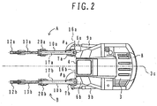
- Fig. 2 is a plan view of the double-arm working machine.
- Upper, lower, left, and right sections of the machine in Fig. 2 are referred to as the right, left, front, and rear, respectively, of the machine in the description given below.
- vertical and horizontal directions of the machine in Fig. 2 are referred to as lateral and longitudinal directions, respectively, of the machine in the description given below.
- the double-arm working machine of the present embodiment is constructed to include an upper swing structure 3 pivotally installed on a lower travel structure 2 which has a travel device 1, and an operator cabin 4 installed almost centrally in a longitudinal direction of the upper swing structure 3.
- the upper swing structure 3 has, across a centerline 3c thereof, a first bracket 6a at a forward right corner of the cabin 4, and a second bracket 6b at a forward left corner of the cabin.
- a power unit 8 with built-in elements such as an engine and pump is disposed in a lateral and rear partition of the cabin 4, inside the upper swing structure 3.
- a swing type of first work front A is installed on the first bracket 6a.
- the first work front A has: a swing post 7a installed on the first bracket 6 so as to be laterally swayable about a vertical axis of the bracket; a boom 10a installed on the swing post 7a so as to be swayable vertically; an arm 12a installed on the boom 10a so as to be swayable vertically; a grapple 20a installed as a first working attachment on the arm 12a so as to be pivotable vertically; a swaying cylinder 9a coupled to the swing post 7a and the upper swing structure 3 in order to sway the swing post 7a laterally about a vertical axis of the cylinder; a boom cylinder 11a (not shown; see the following description of a boom cylinder 11b of a second work front B) that is coupled to the swing post 7a and the boom 10a in order to sway the boom 10a vertically: an arm cylinder 13a coupled to the boom 10a and the arm 12a in
- the grapple 20a is arbitrarily replaceable with other working attachments such as a bucket, breaker, and crusher.
- a second work front B is installed on the front right side of the upper swing structure 3.
- the second work front B essentially of the same configuration as that of the first work front A, is constructed to be left/right symmetric with respect to the first work front A.
- Members of the second work front B that function the same as those of the first work front A are each denoted with a suffix "b", instead of "a" in the reference numbers and symbols assigned to the first work front A, and description of such members is omitted herein.
- Fig. 3 is a perspective view that shows operating devices provided in the present embodiment.
- Fig. 4 is a plan view of the operating devices.
- the cabin 4 internally has an operator's seat 49 and operating devices 50a, 50b on the left and right sides of the operator's seat 49.
- the operating device 50a is for operating the first work front A
- the operating device 50b is for operating the second work front B.
- the operating device 50a includes: a control arm bracket 51a provided on the right side of the operator's seat 49; a control arm 52a installed on the control arm bracket 51a so as to be laterally swayable about a swaying central axis 73a, the control arm 52a being provided to specify lateral swaying of the swing post 7a; a control lever 54a installed horizontally on a distal end portion of the control arm 52a so as to be pivotable vertically and longitudinally, the control lever 54a being provided to specify operation of the boom 10a and the arm 12a; an attachment-turning lever 55a installed on a peripheral section of the control lever 54a so as to be pivotable about an axial center of the control lever 54a, the attachment-turning lever 55a being provided to specify pivotal movement of the grapple 20a; and an attachment control switch 56a installed at the distal end of the control lever 54a in order to specify a start/stop of the grapple 20a.
- the operating device 50a also includes: a control arm position change sensor 57a provided in the control arm bracket 51a in order to sense a variation in a swaying position of the control arm 52a and generate a signal; a control lever vertical position change sensor 581a provided on the control arm 52a in order to sense a variation in a vertical operating position of the control lever 54a and generate a signal; a control lever longitudinal position change sensor 582a provided on the control arm 52a in order to sense a variation in a longitudinal operating position of the control lever 54a and generate a signal; a turning lever position change sensor 59a provided in the control lever 54a in order to sense a variation in a rotating position of the attachment-turning lever 55a and generate a signal; and a control switch position change sensor 60a provided in the attachment-turning lever 55a in order to sense a variation in a position of the attachment control switch 56a and generate a signal.
- a control arm position change sensor 57a provided in the control arm bracket 51a in order to sense a variation
- the operating device 50b provided at the left side of the operator's seat is essentially the same as the operating device 50a in configuration, and is constructed to be almost left/right symmetric with respect to the operating device 50a.
- Members of the operating device 50b that function the same as those of the operating device 50a are each denoted with a suffix "b", instead of "a" in the reference numbers and symbols assigned to the operating device 50a, and description of such members is omitted herein.
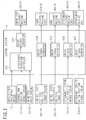
- Fig. 5 is a functional block diagram of control units for the work front A, B. Reference symbols enclosed in parentheses in Fig. 5 denote the associated constituent elements of the second work front B or of its operating device 50b.
- the control units shown in Fig. 5 can be broadly classified into: input units composed of the above operating device's position change sensors, the work front's angle sensors (described later herein), and other elements; a control system 61 which, after receiving an input signal from the input units and then conducting required computations, generates and outputs a driving signal; and output units composed of driving units (described later) which, after receiving an output signal from the input units, operate an associated driving unit of the work front.
- the input units of the control system 61 include an interference preventing switch 110 provided at an appropriate position inside the cabin 4 in order to select whether interference prevention is to be made operative or inoperative.
- the output units of the control system 61 also include: a swing post driving unit 62a, 62b that drives a swing post cylinder 9a, 9b adapted to sway the swing post 7a, 7b laterally; a boom cylinder driving unit 63a, 63b that drives a boom cylinder 11a, 11b adapted to sway the boom 10a, 10b vertically; an arm cylinder driving unit 64a, 64b that drives an arm cylinder 13a, 13b adapted to sway the arm 12a, 12b vertically; an attachment cylinder driving unit 65a, 65b that drives an attachment cylinder 15a, 15b adapted to pivotally move the grapple 20a, 20b; and an attachment driving unit 66a, 66b that activates a drive (not shown) that is adapted for gripping with the grapple 20a, 20b.
- a swing post driving unit 62a, 62b that drives a swing post cylinder 9a, 9b adapted to sway the swing post 7a, 7b later
- the control system 61 has: an interference prevention controller 61F which, on the basis of signals from the control arm position change sensor 57a, 57b and from the swing post angle sensor 67a, 67b, conducts interference prevention control according to a particular difference in angle between the left swing post 7a and the right swing post 7b; a driving signal generator 61A which, on the basis of an output signal from the interference prevention controller 61F, generates a driving signal to be addressed to the swing post cylinder driving unit 62a, 62b; a driving signal generator 61B which, on the basis of a signal from the control lever vertical position change sensor 581a, 581b, generates a driving signal to be addressed to the boom cylinder driving unit 63a, 63b; a driving signal generator 61C which, on the basis of a signal from the control lever lateral position change sensor 582a, 582b, generates a driving signal to be addressed to the arm cylinder driving unit 64a, 64b; a driving signal generator 61D which, on the
- Fig. 6 is a diagram that shows operating directions of an operating device.
- Fig. 7 is a diagram that shows the operating directions of the work front that are associated with the operating directions of the operating device. Operating directions of the second work front B are shown in parentheses in each figure, and description of these operating directions is omitted herein.
- the operator When an operator actuates the first work front A and the second work front B by operating the operating devices 50a, 50b, respectively, the operator sits on the operator's seat 49, rests the elbow of the right arm on an elbow support 77a of an arm rest 53a located on the control arm 52a, grips the attachment-turning lever 55a, and puts the thumb onto the attachment control switch 56a.
- the operator also rests the elbow of the left arm on an elbow support 77b of an arm rest 53b located on the control arm 52b, grips the attachment-turning lever 55b, and puts, for example, the thumb onto the attachment control switch 56b.
- the control lever vertical position change sensor 581a, 581b will transmit an appropriate sensor signal to the driving signal generator 61B within the control system 61.
- the driving signal generator 61B that has received the sensor signal will transmit a driving signal to the boom cylinder driving unit 63a, 63b.
- the boom cylinder driving unit 63a, 63b that has received the driving signal will change length of the boom cylinder 11a, 11b.
- the boom 10a, 10b will then sway (turn vertically as denoted by Y in Fig. 7 ) in the same direction as a turning direction of the control lever 54a, 54b.
- a swaying speed of the boom 10a, 10b will be held in a relationship of monotonic increase (e.g., a proportional relationship) with respect to a variation in a position of the control lever 54a, 54b, and the swaying speed of the boom 10a, 10b will be controlled according to the particular change in the position of the control lever 54a, 54b.
- monotonic increase e.g., a proportional relationship
- a swaying speed of the arm 12a, 12b is held in a relationship of monotonic increase (e.g., a proportional relationship) with respect to a variation in a position of the control lever 54a, 54b, and the swaying speed of the arm 12a, 12b will be controlled according to the particular change in the position of the control lever 54a, 54b.
- monotonic increase e.g., a proportional relationship
- the attachment-turning lever 55a, 55b causes the attachment-turning lever position change sensor 59a, 59b to transmit an appropriate sensor signal to the driving signal generator 61D within the control system 61.
- the driving signal generator 61D that has received the sensor signal transmits a driving signal to the attachment cylinder driving unit 65a, 65b.
- the attachment cylinder driving unit 65a, 65b that has received the driving signal changes length of the attachment cylinder 15a, 15b.
- the grapple 20a, 20b then turns (as denoted by Z in Fig. 7 ) in the same direction as the turning direction of the attachment-turning lever 55a, 55b.
- a turning speed of the grapple 20a, 20b at this time is held in a relationship of monotonic increase (e.g., a proportional relationship) with respect to a variation in a position of the attachment-turning lever 55a, 55b, and the turning speed of the grapple 20a, 20b will be controlled according to the particular change in the position of the attachment-turning lever 55a, 55b.
- monotonic increase e.g., a proportional relationship
- the attachment control switch 56a, 56b causes the attachment control switch position change sensor 60a, 60b to transmit an appropriate sensor signal to the driving signal generator 61E within the control system 61.
- the driving signal generator 61E that has received the sensor signal transmits a driving signal to the attachment driving unit 66a, 66b.
- the attachment driving unit 66a, 66b that has received the driving signal drives claws of the grapple 20a, 20b to open or close the claws.
- An opening or closing speed of the grapple 20a, 20b at this time is held in a relationship of monotonic increase (e.g., a proportional relationship) with respect to a variation in a position of the attachment control switch 56a, 56b, and a driving speed of the attachment will be controlled according to the particular change in the position of the attachment control switch 56a, 56b.
- monotonic increase e.g., a proportional relationship
- the grapple 20a, 20b can be replaced with other attachments.
- operation of the mounted attachment is specified from the attachment control switch 56a, 56b.
- operation of the breaker is turned on/off by operating the attachment control switch 56a, 56b.
- the control arm position change sensor 57a, 57b and the swing post angle sensor 67a, 67b will transmit an appropriate sensor signal to the interference prevention controller 61F (described later) within the control system 61.
- the interference prevention controller 61F that has received the sensor signal will compute a command signal that incorporates prevention of interference between the work fronts A, B and transmit this signal to the driving signal generator 61A.
- the driving signal generator 61A will transmit a driving signal to the swing post cylinder driving unit 62a, 62b.
- the swing post cylinder driving unit 62a, 62b that has received the driving signal will change length of the swing post cylinder 9a, 9b.
- the swing post 7a, 7b will then be swayed (see W, Fig. 7 ) in the same direction as that in which the control arm 52a, 52b changes in position.
- a swaying speed of the swing post 7a, 7b will be held in a relationship of monotonic increase (e.g., a proportional relationship) with respect to a variation in a position of the control arm 52a, 52b, and the swaying speed of the swing post 7a, 7b will be controlled according to the particular change in the position of the control arm 52a, 52b.
- monotonic increase e.g., a proportional relationship
- an angle of the right swing post 7a is taken as ⁇ a (>0), and an angle of the left swing post 7b, as ⁇ b (>0).
- a differential between the above two angles is taken as ⁇ c ( ⁇ b- ⁇ a).
- the angles ⁇ a, ⁇ b can be defined in the same manner for the left swing post 7a and the right swing post 7b.
- angles formed by centerlines 17a, 17b of the respective work fronts A, B with respect to reference lines 16a, 16b each extending from a turning center of the associated swing post 7a, 7b, towards the right side thereof, are defined as the angles ⁇ a, ⁇ b.
- the reference lines 16a, 16b are parallel to each other.
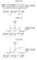
- Fig. 8 is a conceptual diagram that represents a relationship between work front differential angle ⁇ c and interference/non-interference.
- a method of determining the threshold value ⁇ c1 is not limited. However, if the assigned threshold value is, for example, the largest usable safety value, when the work fronts A and B are both extended to their maximum horizontal operating length for a maximum swinging radius, a differential angle at which the work fronts A, B are liable to come into contact on an extension of the centerline 3c of the upper swing structure 3, or an angle greater than this differential angle may be determined as the threshold value ⁇ c1.
- the threshold value ⁇ c1 thus determined is previously stored within the interference prevention controller 61F, and the area of ⁇ c ⁇ c1 that is a differential angle range in which the work fronts A, B are liable to come into contact is defined as an interference danger area N.
- an area of ⁇ > ⁇ c1 is an area in which, even when the work fronts A, B are present in an area that does not permit the work fronts A, B to interfere for their structural reasons while in a stopped state, the work fronts A, B are difficult to stop abruptly, if the work fronts, even during operation in a non-interference area, are operated to make relative approaches near the interference danger area, both work fronts are liable to enter the interference danger area and interfere, depending on operating speed.
- a threshold value ⁇ c2 (> ⁇ c1) that has been assigned with the possible interference taken into account is previously stored within the interference prevention controller 61F, and the area of ⁇ c1 ⁇ c ⁇ c2 that is the assigned differential angle range contiguous to the interference danger area is defined as a semi-interference danger area.
- An area of ⁇ c > ⁇ c2 is defined as a normal area in which the interference between the work fronts A, B is unlikely, regardless of their operating states.
- Fig. 9 is a diagram showing an example of a relationship between an interference prevention controller output signal level and left/right work front differential angle obtained during work front swinging for relative approaching.
- a horizontal axis denotes the differential angle ⁇ c and a vertical axis denotes the output signal.
- This output signal is already made dimensionless through division by an input signal.
- the output signal value becomes 1 and an original output signal value that has been calculated from the input signal is output intact.
- the output signal value becomes ⁇ (0 ⁇ 1) and the original output signal value that has been calculated from the input signal is subtracted through a multiplication by a certain ⁇ value before being output.
- the differential angle ⁇ c between the work fronts A, B exists in the interference danger area N, the output signal value becomes 0 and the output signal specifying a swinging stop for the work fronts A, B is output.
- the interference prevention controller 61F directly transmits the output signal to the driving signal generator 61A without subtracting the output signal value that has been computed using the input signal received from the control arm position change sensor 57a, 57b.
- the interference prevention controller 61F subtracts the output signal value that has been computed using the input signal received from the control arm position change sensor 57a, 57b, and then transmits the output signal to the driving signal generator 61A.
- the interference prevention controller 61F directly transmits the output signal to the driving signal generator 61A without subtracting the output signal value that has been computed using the input signal received from the control arm position change sensor 57a, 57b.
- the interference prevention controller 61F When the differential angle ⁇ c between both swing posts 7a, 7b already exists in the interference danger area N and the input signal from the control arm position change sensor 57a, 57b is a signal that moves the work fronts A, B further away from the semi-interference danger area M, that is, a signal that commands the work fronts A, B to move closer to each other, the interference prevention controller 61F generates the output signal for stopping the swing operation of the work fronts A, B, and transmits the output signal to the driving signal generator 61A.
- the interference prevention controller 61F directly transmits the output signal to the driving signal generator 61A without subtracting the output signal value that has been computed using the input signal received from the control arm position change sensor 57a, 57b.
- the above-described interference prevention control by the interference prevention controller 61F is turned on/off by the input signal from the interference preventing switch 110. That is to say, when the input signal from the interference preventing switch 110 is on, the interference prevention controller 61F makes the interference prevention control effective, and as described above, changes a gain of the output signal to the driving signal generator 61A according to area. Conversely, when the input signal from the interference preventing switch 110 is off, the interference prevention controller 61F makes the interference prevention control ineffective, and directly transmits the output signal to the driving signal generator 61A without subtracting the output signal value that has been computed using the input signal. That is to say, the output signal in Fig. 9 is set to take a value of 1 at all times for each area.
- the machine since the machine has the left work front A and the right work front B, it is possible, for example, during an automobile dismantling operation, to fix a bodywork of the automobile by operating the first work front A, and remove parts of the automobile by operating the second work front B.
- the structure can be destroyed with one work front while gripping the structure with the other work front.
- this section can be supported using the work fronts A, B to prevent falling or dropping, without lifting the section by means of a crane or the like, and the dismantling operation can be performed efficiently with a minimum manpower requirement.
- providing the semi-interference danger area M and assigning the work fronts A, B such a positional relationship that causes the work fronts to approach each other in the semi-interference danger area M makes it possible to reduce a relative operating speed of the work fronts A, B before the work fronts A, B move into the interference danger area N the and hence to prevent the work fronts from being damaged or destroyed by interference.
- a signal level of the output signal which the interference prevention controller 61F transmits when the relationship in position between the work fronts A, B exists in the semi-interference danger area is not limited to/by the aspect shown in Fig. 9 (i.e., reduction ratio " ⁇ " is fixed), and this reduction ratio may be lowered stepwise or any one of the aspects described as examples below may be employed.
- Fig. 10 is a diagram showing another example of a relationship between the interference prevention controller output signal level and left/right work front differential angle obtained during work front swinging for relative approaching.
- the horizontal and vertical axes shown in Fig. 10 denote the same as in Fig. 9 .
- the output signal in the semi-interference danger area M is set to continuously decrease from 1 to 0 (zero) as the signal approaches the interference danger area N, and particularly in the present example, the above relationship is defined by a nonlinear curve free of a discontinuous point.
- the relationship in position between the work fronts A, B approaches the interference danger area N the relative speed at which one work front approaches the other work front will be suppressed, so the swing post cylinder 9a, 9b can be stopped more gently than in the example of Fig. 9 .
- the relationship between the differential angle ⁇ c and the output signal is defined using a nonlinear curve free of a discontinuous point, to stop the swing operation of the work fronts A, B more smoothly and more gently.
- Fig. 11 is a diagram showing yet another example of a relationship between the interference prevention controller output signal level and left/right work front differential angle obtained during work front swinging for relative approaching.
- the horizontal and vertical axes shown in Fig. 11 denote the same as in Fig. 9 .
- the output signal in the semi-interference danger area M is also set to continuously decrease from 1 to 0 (zero) as the signal approaches the interference danger area N.
- the above relationship is defined by a linear curve having a definite gradient, and a connection point with respect to the output signal in the normal area L/interference danger area N is discontinuous.
- Figs. 12 to 14 are diagrams that show further examples of a relationship between the interference prevention controller output signal level and left/right work front differential angle obtained during work front swinging for relative approaching.
- a horizontal axis denotes the differential angle ⁇ c, as in Fig. 9
- a vertical axis denotes an upper-limit value of the output signal.
- the output signal that has been calculated according to the particular input signal level in the semi-interference danger area M is multiplied by a coefficient to reduce the swinging speed, whereas, in the examples of Figs. 12-14 , an upper-limit value of the swinging speed is set to be as shown in either figure, and the swinging speed of the work front A, B in the semi-interference danger area M is limited and reduced. How great the manipulated variable is, the output signal is controlled to stay within the upper limit. Essentially the same advantageous effects as obtained in the examples of Figs. 9-11 can be obtained by using the above method.
- the interference danger area N and the semi-interference danger area M have been defined for the swinging differential angle ⁇ c and the swing operation of the work front A, B has been controlled on the basis only of the differential angle ⁇ c.
- the interference danger area N, the semi-interference danger area M, and the normal area L are defined considering a posture (e.g., a vertical position) of the work front A, B in addition to the differential angle ⁇ c, and operation associated with vertical swaying of the work fronts A, B, as well as the swing operation thereof, is appropriately controlled to prevent interference between both work fronts.
- the operation associated with vertical swaying of the work fronts A, B refers to the sway operation of the booms 10a, 10b, arms 12a, 12b, and grapples 20a, 20b.
- Postures of the booms 10a, 10b, arms 12a, 12b, and grapples 20a, 20b are calculated from turning angles of the booms 10a, 10b with respect to the swing posts 7a, 7b, turning angles of the arms 12a, 12b with respect to the booms 10a, 10b, and turning angles of the grapples 20a, 20b with respect to the arms 12a, 21b.
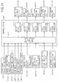
- Fig. 15 is a functional block diagram of the control system for the work front A, B in the double-arm working machine according to the second embodiment.
- input units of the control system 61A in the present embodiment include: boom angle sensors 68a, 68b that sense the turning angles of the booms 10a, 10b with respect to the swing posts 7a, 7b, arm angle sensors 69a, 69b that sense the turning angles of the arms 12a, 12b with respect to the booms 10a, 10b, and attachment angle sensors 70a, 70b that sense the turning angles of the grapples 20a, 20b with respect to the arms 12a, 12b.
- Signals from the position change sensors 57a, 57b, 581a, 581b, 582a, 582b, 59a, 59b of the operating devices 50a, 50b, signals from the angle sensors 67a, 67b, 68a, 68b, 69a, 69b, 70a, 70b of the work fronts A, B, and signals from the interference preventing switch 110 are input to an interference prevention controller 61FA provided within the control system 61A.
- the interference prevention controller 61FA computes the relationship in position between the work fronts A, B (i.e., the differential angle ⁇ c and the postures), and prevents interference between the work fronts A, B by considering the swinging angles and postures thereof (the prevention of the interference will be described in detail later herein).
- Output signals to the driving signal generators 61A to 61E are computed from respective input signals by the interference prevention controller 61FA, and output to the associated driving signal generators.
- Fig. 16 is a side view that shows external appearance of the double-arm working machine according to the second embodiment of the present invention.
- Fig. 17 is a plan view of the double-arm working machine.
- step 1 as illustrated by way of example in Figs. 16 and 17 , the quantities and positions of interference prevention reference points 120 to become the basis for interference prevention control are set for the work fronts A, B (i.e., the booms 10a, 10b, the arms 12a, 12b, and the grapples 20a, 20b). Alternatively, these values may be preset.
- the quantities of interference prevention reference points 120 on the work fronts A and B are set as “m” and "n”, respectively.
- the interference danger radius Ri or Rj here refers to a radius at which the work fronts A, B are liable to come into contact with each other if the interference danger radius of one work front interferes with that of the other work front.
- the work fronts A, B assume such a state that the work fronts are surrounded by a tubular virtual space formed by linking the virtual spheres of the radii Ri, Rj with the interference prevention reference points 120i, 120j as the respective centers.
- the range of such a 3D-like work front positional relationship that makes the tubular virtual space interfere with the similar virtual space of the other work front becomes the interference danger area N.
- the interference danger area N assumes such a state that the area N is surrounded by another tubular virtual space formed by linking the virtual spheres of the radii Ri, Rj with the interference prevention reference points 120i, 120j as the respective centers.
- the range of such a three-dimensional work front positional relationship that makes the tubular virtual space interfere with the similar virtual space of the other work front becomes the semi-interference danger area M. That is to say, the semi-interference danger area M is adjacent to and surrounds the interference danger area N.
- a fundamental coordinate system 130 is provided on the upper swing structure 3.
- a point intersecting with a lower face of the upper swing structure 3, on a swing centerline 3a thereof, is set as an origin 130a of the fundamental coordinate system.
- coordinate axes are taken with the fundamental coordinate system origin 130a as an origin of the axes. That is to say, an X-axis is taken in a rightward direction of the upper swing structure 3, a Y-axis in a forward direction, and a Z-axis in an upward direction.
- position coordinates of all interference prevention reference points 120i, 120j in the fundamental coordinate system 130 are calculated from the sensor signals sent from the angle sensors 67a, 67b, 68a, 68b, 69a, 69b, 70a, 70b of the work fronts A, B.
- the calculated position coordinates of each interference prevention reference point 120i for the first work front A, in the fundamental coordinate system 130 are defined as Pi (xi, yi, zi), and the calculated position coordinates of each interference prevention reference point 120j for the second work front B, as Pj (xj, yj, zj).
- Distances "sij" from all interference prevention reference points 120i on the first work front A to all interference prevention reference points 120j on the second work front B where front-to-front contact is likely to occur are calculated from the above-defined position coordinates Pi, Pj. The calculations are conducted for each interference prevention reference point 120i.
- ⁇ (xi - xj) 2 + (yi - yj) 2 + (zi - zj) 2 ⁇ 1/2 ".
- the interference prevention reference points 120i, 120j at which a differential obtained as "Sij - (Ri + Rj)" by subtracting a sum total (Ri + Rj) of interference danger radii from the reference point - reference point distance "Sij” becomes a minimum are extracted and the distance "Sij" between the two associated reference points is expressed as the shortest distance "Sm” between reference points.
- Fig. 18 is a conceptual diagram that shows a relationship between the shortest distance from one reference point on the left/right work front to another reference point, and left/right work front interference/non-interference.
- the above-described normal area L, semi-interference danger area M, and interference danger area N that have been defined as in Fig. 18 are stored within the interference prevention controller 61F.
- the area in which the distance between the two extracted interference prevention reference points, 120i, 120j, namely, the shortest distance "Sm" between reference points becomes equal to or smaller than the sum total (Ri+Rj) of the interference danger radii, that is, the area in which "Sm ⁇ (Ri + Rj)" holds is defined as an interference danger area N.
- the area in which the shortest distance "Sm” between reference points becomes greater than the sum total (Ri + Rj) of the interference danger radii and equal to or smaller than a sum total (RQi + RQj) of semi-interference danger radii that is, the area in which "(Ri + Rj) ⁇ Sm ⁇ (RQi + RQj)" holds is defined as the semi-interference danger area M.
- the area in which the shortest distance "Sm” between reference points becomes greater than the sum total (RQi + RQj) of the semi-interference danger radii, that is, the area in which "Sm > (RQi + RQj)" holds is defined as a normal area L.
- Step 5 Output signal generation based on interference area discrimination>
- Fig. 19 is a diagram showing an example of a relationship between the output signal level of the interference prevention controller 61FA and shortest distance "Sm" from one reference point to another, obtained for the left/right work front during swinging thereof for relative approaching.
- a horizontal axis denotes the shortest distance "Sm” from one reference point to another, and a vertical axis denotes the output signal. This output signal is already made dimensionless.
- Fig. 19 is a diagram showing an example of a relationship between the output signal level of the interference prevention controller 61FA and shortest distance "Sm" from one reference point to another, obtained for the left/right work front during swinging thereof for relative approaching.
- a horizontal axis denotes the shortest distance "Sm” from one reference point to another
- a vertical axis denotes the output signal. This output signal is already made dimensionless.
- the interference prevention controller 61FA directly transmits the output signal to the associated driving signal generator without subtracting the output signal value that has been computed using the input signals sent from the position change sensors 57a, 57b, 581a, 581b, 582a, 582b, 59a, 59b, 60a, 60b of the operating device 50a, 50b.
- the interference prevention controller 61FA subtracts the output signal value that has been computed using the input signals obtained from the position change sensors 57a, 57b, 581a, 581b, 582a, 582b, 59a, 59b, 60a, 60b, and transmits the output signal to the associated driving signal generator.
- the interference prevention controller 61FA directly transmits the output signal to the associated driving signal generator without subtracting the output signal value that has been computed using the input signals obtained from the position change sensors 57a, 57b, 581a, 581b, 582a, 582b, 59a, 59b, 60a, 60b.
- the interference prevention controller 61FA When the shortest distance "Sm" between reference points on the work front A, B lies in the interference danger area N and the input signal from the position change sensor 57a, 57b, 581a, 581b, 582a, 582b, 59a, 59b, 60a, 60b is the signal that reduces the shortest distance "Sm", that is, the signal that makes the work fronts A, B approach each other, the interference prevention controller 61FA generates output signals that stop the operation of the work fronts A, B and outputs the generated signals to the associated driving signal generators. In this case, of all output signals to each associated driving signal generator, only an operation-stopping signal containing a directional component which makes the work fronts A, B approach each other may be generated and output.
- the interference prevention controller 61FA directly transmits the output signal to the associated driving signal generator without subtracting the output signal value that has been computed using the input signals obtained from the position change sensors 57a, 57b, 581a, 581b, 582a, 582b, 59a, 59b, 60a, 60b.
- the interference prevention controller 61FA in the present embodiment so that whether to make interference prevention control effective or ineffective can be selected using the input signal obtained from the interference preventing control 110 provided in the cabin 4. It is also possible to adopt the construction that allows selection of the interference prevention control function in the first embodiment or the interference prevention control function in the present (second) embodiment, not only on/off selection of interference prevention control.
- this control function prevents the occurrence of the inconvenience that in spite of the work fronts A, B being unlikely to come into contact, two-dimensional judgment on interference/non-interference slows down (or stops) the operation of the work front A, B.
- the signal level of the output signal which the interference prevention controller 61FA transmits when the relationship in position between the work fronts A, B exists in the semi-interference danger area M is not limited to/by the aspect shown in Fig. 9 (i.e., reduction ratio " ⁇ " is fixed), and this reduction ratio may be lowered stepwise or any one of the aspects described as examples below may be employed.
- Fig. 20 is a diagram showing another example of a relationship between the interference prevention controller 61FA output signal level and shortest distance from one reference point to another, obtained for the left/right work front during swinging thereof for relative approaching.
- the horizontal and vertical axes shown in Fig. 20 denote the same as in Fig. 19 .
- the output signal in the semi-interference danger area M is set to continuously decrease from 1 to 0 (zero) as the signal approaches the interference danger area N, and particularly in the present example, the above relationship is defined by a nonlinear curve free of a discontinuous point.
- the relationship in position between the work fronts A, B approaches the interference danger area N the relative speed at which one work front approaches the other work front will be suppressed, so the swing post cylinder 9a, 9b can be stopped more gently than in the example of Fig. 19 .
- the relationship between the shortest distance "Sm" and the output signal is defined using a nonlinear curve free of a discontinuous point, to stop the swing operation of the work fronts A, B more smoothly and more gently.
- Fig. 21 is a diagram showing yet another example of a relationship between the interference prevention controller 61FA output signal level and shortest distance from one reference point to another, obtained during left/right work front swinging for relative approaching.
- the horizontal and vertical axes shown in Fig. 21 denote the same as in Fig. 19 .
- the output signal in the semi-interference danger area M is also set to continuously decrease from 1 to 0 (zero) as the signal approaches the interference danger area N.
- the above relationship is defined by a linear curve having a definite gradient, and a connection point with respect to the output signal in the normal area L/interference danger area N is discontinuous.
- Figs. 22 to 24 are diagrams that show further examples of a relationship between the interference prevention controller 61FA output signal level and shortest distance from one reference point to another, obtained during work front swinging for relative approaching.
- a horizontal axis denotes the shortest distance "Sm" between reference points, as in Fig. 19
- a vertical axis denotes an upper-limit value of the output signal.
- the output signal that has been calculated according to the particular input signal level in the semi-interference danger area M is multiplied by a coefficient to reduce the operating speed, whereas, in the examples of Figs. 22-24 , an upper-limit value of the operating speed is set to be as shown in either figure, and the operating speed of the work front A, B in the semi-interference danger area M is limited and reduced. How great the manipulated variable is, the output signal is controlled to stay within the upper limit. Essentially the same advantageous effects as obtained in the examples of Figs. 19-21 can be obtained by using the above method.
- both work fronts are stopped if interference between the work fronts in the interference danger area N is still likely.
- the interference may be avoidable by changing the operating direction(s) of one or both of the work fronts. For example, if the work fronts A, B interfere during swinging, the interference can be avoided by assigning (or increasing) an operating speed of a directional (vertical) component orthogonal to the operating direction, and shifting vertically the positional relationship between the work fronts A, B.
- the interference can, of course, be avoided by assigning (or increasing) a swinging speed which moves the work fronts A, B away from each other, and shifting laterally the positional relationship between the work fronts A, B.
Applications Claiming Priority (2)
| Application Number | Priority Date | Filing Date | Title |
|---|---|---|---|
| JP2006151455A JP4823767B2 (ja) | 2006-05-31 | 2006-05-31 | 双腕作業機械 |
| PCT/JP2007/050253 WO2007138755A1 (ja) | 2006-05-31 | 2007-01-11 | 双腕作業機械 |
Publications (3)
| Publication Number | Publication Date |
|---|---|
| EP2022899A1 EP2022899A1 (en) | 2009-02-11 |
| EP2022899A4 EP2022899A4 (en) | 2015-12-02 |
| EP2022899B1 true EP2022899B1 (en) | 2017-07-12 |
Family
ID=38778282
Family Applications (1)
| Application Number | Title | Priority Date | Filing Date |
|---|---|---|---|
| EP07706600.9A Not-in-force EP2022899B1 (en) | 2006-05-31 | 2007-01-11 | Double-arm working machine |
Country Status (4)
| Country | Link |
|---|---|
| US (1) | US8137047B2 (ja) |
| EP (1) | EP2022899B1 (ja) |
| JP (1) | JP4823767B2 (ja) |
| WO (1) | WO2007138755A1 (ja) |
Families Citing this family (19)
| Publication number | Priority date | Publication date | Assignee | Title |
|---|---|---|---|---|
| EP2116670B1 (en) * | 2008-01-07 | 2013-11-06 | Hitachi Construction Machinery Co., Ltd | Double arm type work machine |
| JP2009197439A (ja) * | 2008-02-20 | 2009-09-03 | Caterpillar Japan Ltd | 作業機械における干渉防止制御装置 |
| DE102009037880B4 (de) * | 2009-08-18 | 2021-12-30 | Robert Bosch Gmbh | Mobile Arbeitsmaschine mit einer Regelvorrichtung mit einem Arbeitsarm und Verfahren zur Arbeitspunktregelung eines Arbeitsarms einer mobilen Arbeitsmaschine |
| JP2012006132A (ja) * | 2010-06-28 | 2012-01-12 | Hitachi Constr Mach Co Ltd | 双腕作業機械 |
| JP5410373B2 (ja) * | 2010-07-02 | 2014-02-05 | 日立建機株式会社 | 双腕型作業機械 |
| US20120315120A1 (en) * | 2011-06-08 | 2012-12-13 | Hyder Jarrod | Work machine |
| JP5488549B2 (ja) * | 2011-08-16 | 2014-05-14 | 株式会社安川電機 | ロボット制御システムおよびロボット制御方法 |
| US9580885B2 (en) * | 2011-10-19 | 2017-02-28 | Sumitomo Heavy Industries, Ltd. | Swing operating machine and method of controlling swing operating machine |
| US9458602B2 (en) * | 2012-02-15 | 2016-10-04 | Hitachi Construction Machinery Co., Ltd. | Dual-arm work machine |
| CN102773853B (zh) * | 2012-07-10 | 2014-12-24 | 北京航空航天大学 | 面向双臂工程机械的属具位置操控及自避碰监控方法 |
| CN102808431B (zh) * | 2012-08-21 | 2015-05-20 | 长安大学 | 双挖臂挖掘机 |
| JP5969444B2 (ja) * | 2013-09-18 | 2016-08-17 | 日立建機株式会社 | 作業機械の操作装置 |
| JP6511387B2 (ja) * | 2015-11-25 | 2019-05-15 | 日立建機株式会社 | 建設機械の制御装置 |
| KR101825659B1 (ko) * | 2016-06-09 | 2018-02-05 | (주)케이엔알시스템 | 내부유로를 포함하는 재난 복구용 유압기계의 암 |
| KR101785341B1 (ko) * | 2016-06-15 | 2017-10-17 | 한국생산기술연구원 | 재난 구조용 유압기계의 포터블 어태치먼트 |
| JP6962743B2 (ja) * | 2017-08-23 | 2021-11-05 | 大成建設株式会社 | 作業車両用旋回制御システム |
| CN112218595A (zh) | 2018-05-18 | 2021-01-12 | 奥瑞斯健康公司 | 用于机器人使能的远程操作的系统的控制器 |
| JP2020148074A (ja) * | 2019-03-15 | 2020-09-17 | ヤンマーパワーテクノロジー株式会社 | 作業機械の接触防止装置 |
| JP7090859B1 (ja) * | 2022-05-13 | 2022-06-27 | 株式会社Tmt | 作業車両 |
Family Cites Families (6)
| Publication number | Priority date | Publication date | Assignee | Title |
|---|---|---|---|---|
| JPS6352991A (ja) * | 1986-08-20 | 1988-03-07 | トキコ株式会社 | 工業用ロボツト |
| WO1998030759A1 (fr) * | 1997-01-07 | 1998-07-16 | Hitachi Construction Machinery Co., Ltd. | Dispositif de prevention des heurts pour excavatrice hydraulique a fleche a deux bras |
| JPH11181815A (ja) * | 1997-12-19 | 1999-07-06 | Hitachi Constr Mach Co Ltd | 作業機械 |
| JP3314064B2 (ja) * | 1999-12-17 | 2002-08-12 | 株式会社タカハシワークス | 保護装置付ツインアーム作業機 |
| JP4369329B2 (ja) * | 2004-08-31 | 2009-11-18 | 日立建機株式会社 | 作業機械 |
| DE102006042370A1 (de) * | 2006-09-08 | 2008-03-27 | Deere & Company, Moline | Ladegerät |
-
2006
- 2006-05-31 JP JP2006151455A patent/JP4823767B2/ja not_active Expired - Fee Related
-
2007
- 2007-01-11 US US11/909,782 patent/US8137047B2/en not_active Expired - Fee Related
- 2007-01-11 WO PCT/JP2007/050253 patent/WO2007138755A1/ja active Application Filing
- 2007-01-11 EP EP07706600.9A patent/EP2022899B1/en not_active Not-in-force
Also Published As
| Publication number | Publication date |
|---|---|
| JP4823767B2 (ja) | 2011-11-24 |
| EP2022899A4 (en) | 2015-12-02 |
| US20100183416A1 (en) | 2010-07-22 |
| WO2007138755A1 (ja) | 2007-12-06 |
| US8137047B2 (en) | 2012-03-20 |
| EP2022899A1 (en) | 2009-02-11 |
| JP2007319962A (ja) | 2007-12-13 |
Similar Documents
| Publication | Publication Date | Title |
|---|---|---|
| EP2022899B1 (en) | Double-arm working machine | |
| JP4841671B2 (ja) | 双腕作業機械 | |
| JP7216074B2 (ja) | ショベル | |
| KR102601073B1 (ko) | 작업 기계 | |
| CN112384663A (zh) | 挖土机 | |
| WO2020166241A1 (ja) | 監視装置及び建設機械 | |
| JP4369329B2 (ja) | 作業機械 | |
| JP7217691B2 (ja) | 建設機械 | |
| JP6539630B2 (ja) | 超小旋回型油圧ショベル | |
| JP3692228B2 (ja) | 干渉防止機能付き建設作業機械 | |
| JP2005248502A (ja) | 作業機の干渉防止装置 | |
| JP3357120B2 (ja) | 作業機の干渉防止装置 | |
| JP4473057B2 (ja) | 建設機械の干渉防止装置 | |
| JP3310776B2 (ja) | 作業機の干渉防止装置 | |
| WO2023149104A1 (ja) | 作業機械および作業機械の制御方法 | |
| JP2002068671A (ja) | 油圧ショベルのクレーンフック格納検出装置の配線構造 | |
| JP7397235B2 (ja) | 作業機械 | |
| JPH07109750A (ja) | 作業機の干渉防止装置 | |
| JP4716925B2 (ja) | オフセット式油圧ショベルの干渉防止装置 | |
| JPH06136783A (ja) | 建設機械の作業範囲制御方法 | |
| JP5015068B2 (ja) | オフセット式作業機 | |
| JPH08291531A (ja) | 建設機械の作業機干渉防止装置 | |
| JP2001123473A (ja) | 建設機械の作業機制御装置 | |
| JP2793953B2 (ja) | 油圧ショベルのフロント制御装置 | |
| JPH101980A (ja) | 油圧ショベルのフロント制御装置 |
Legal Events
| Date | Code | Title | Description |
|---|---|---|---|
| PUAI | Public reference made under article 153(3) epc to a published international application that has entered the european phase |
Free format text: ORIGINAL CODE: 0009012 |
|
| 17P | Request for examination filed |
Effective date: 20080331 |
|
| AK | Designated contracting states |
Kind code of ref document: A1 Designated state(s): AT BE BG CH CY CZ DE DK EE ES FI FR GB GR HU IE IS IT LI LT LU LV MC NL PL PT RO SE SI SK TR |
|
| AX | Request for extension of the european patent |
Extension state: AL BA HR MK RS |
|
| DAX | Request for extension of the european patent (deleted) | ||
| RA4 | Supplementary search report drawn up and despatched (corrected) |
Effective date: 20151030 |
|
| RIC1 | Information provided on ipc code assigned before grant |
Ipc: E02F 9/20 20060101ALI20151026BHEP Ipc: E02F 3/38 20060101ALI20151026BHEP Ipc: B25J 9/00 20060101ALI20151026BHEP Ipc: E02F 9/24 20060101ALI20151026BHEP Ipc: E02F 3/36 20060101AFI20151026BHEP Ipc: E02F 3/96 20060101ALI20151026BHEP |
|
| 17Q | First examination report despatched |
Effective date: 20151119 |
|
| RIC1 | Information provided on ipc code assigned before grant |
Ipc: E02F 9/24 20060101ALI20161222BHEP Ipc: B25J 9/00 20060101ALI20161222BHEP Ipc: E02F 3/96 20060101ALI20161222BHEP Ipc: E02F 3/36 20060101AFI20161222BHEP Ipc: E02F 9/20 20060101ALI20161222BHEP Ipc: E02F 3/38 20060101ALI20161222BHEP |
|
| GRAP | Despatch of communication of intention to grant a patent |
Free format text: ORIGINAL CODE: EPIDOSNIGR1 |
|
| STAA | Information on the status of an ep patent application or granted ep patent |
Free format text: STATUS: GRANT OF PATENT IS INTENDED |
|
| INTG | Intention to grant announced |
Effective date: 20170127 |
|
| GRAS | Grant fee paid |
Free format text: ORIGINAL CODE: EPIDOSNIGR3 |
|
| GRAA | (expected) grant |
Free format text: ORIGINAL CODE: 0009210 |
|
| STAA | Information on the status of an ep patent application or granted ep patent |
Free format text: STATUS: THE PATENT HAS BEEN GRANTED |
|
| AK | Designated contracting states |
Kind code of ref document: B1 Designated state(s): AT BE BG CH CY CZ DE DK EE ES FI FR GB GR HU IE IS IT LI LT LU LV MC NL PL PT RO SE SI SK TR |
|
| REG | Reference to a national code |
Ref country code: GB Ref legal event code: FG4D |
|
| REG | Reference to a national code |
Ref country code: CH Ref legal event code: EP |
|
| REG | Reference to a national code |
Ref country code: AT Ref legal event code: REF Ref document number: 908458 Country of ref document: AT Kind code of ref document: T Effective date: 20170715 |
|
| REG | Reference to a national code |
Ref country code: IE Ref legal event code: FG4D |
|
| REG | Reference to a national code |
Ref country code: DE Ref legal event code: R096 Ref document number: 602007051601 Country of ref document: DE |
|
| REG | Reference to a national code |
Ref country code: SE Ref legal event code: TRGR |
|
| REG | Reference to a national code |
Ref country code: NL Ref legal event code: MP Effective date: 20170712 |
|
| REG | Reference to a national code |
Ref country code: LT Ref legal event code: MG4D |
|
| REG | Reference to a national code |
Ref country code: AT Ref legal event code: MK05 Ref document number: 908458 Country of ref document: AT Kind code of ref document: T Effective date: 20170712 |
|
| PG25 | Lapsed in a contracting state [announced via postgrant information from national office to epo] |
Ref country code: FI Free format text: LAPSE BECAUSE OF FAILURE TO SUBMIT A TRANSLATION OF THE DESCRIPTION OR TO PAY THE FEE WITHIN THE PRESCRIBED TIME-LIMIT Effective date: 20170712 Ref country code: AT Free format text: LAPSE BECAUSE OF FAILURE TO SUBMIT A TRANSLATION OF THE DESCRIPTION OR TO PAY THE FEE WITHIN THE PRESCRIBED TIME-LIMIT Effective date: 20170712 Ref country code: LT Free format text: LAPSE BECAUSE OF FAILURE TO SUBMIT A TRANSLATION OF THE DESCRIPTION OR TO PAY THE FEE WITHIN THE PRESCRIBED TIME-LIMIT Effective date: 20170712 Ref country code: NL Free format text: LAPSE BECAUSE OF FAILURE TO SUBMIT A TRANSLATION OF THE DESCRIPTION OR TO PAY THE FEE WITHIN THE PRESCRIBED TIME-LIMIT Effective date: 20170712 |
|
| PG25 | Lapsed in a contracting state [announced via postgrant information from national office to epo] |
Ref country code: LV Free format text: LAPSE BECAUSE OF FAILURE TO SUBMIT A TRANSLATION OF THE DESCRIPTION OR TO PAY THE FEE WITHIN THE PRESCRIBED TIME-LIMIT Effective date: 20170712 Ref country code: GR Free format text: LAPSE BECAUSE OF FAILURE TO SUBMIT A TRANSLATION OF THE DESCRIPTION OR TO PAY THE FEE WITHIN THE PRESCRIBED TIME-LIMIT Effective date: 20171013 Ref country code: PL Free format text: LAPSE BECAUSE OF FAILURE TO SUBMIT A TRANSLATION OF THE DESCRIPTION OR TO PAY THE FEE WITHIN THE PRESCRIBED TIME-LIMIT Effective date: 20170712 Ref country code: IS Free format text: LAPSE BECAUSE OF FAILURE TO SUBMIT A TRANSLATION OF THE DESCRIPTION OR TO PAY THE FEE WITHIN THE PRESCRIBED TIME-LIMIT Effective date: 20171112 Ref country code: ES Free format text: LAPSE BECAUSE OF FAILURE TO SUBMIT A TRANSLATION OF THE DESCRIPTION OR TO PAY THE FEE WITHIN THE PRESCRIBED TIME-LIMIT Effective date: 20170712 Ref country code: BG Free format text: LAPSE BECAUSE OF FAILURE TO SUBMIT A TRANSLATION OF THE DESCRIPTION OR TO PAY THE FEE WITHIN THE PRESCRIBED TIME-LIMIT Effective date: 20171012 |
|
| REG | Reference to a national code |
Ref country code: DE Ref legal event code: R097 Ref document number: 602007051601 Country of ref document: DE |
|
| PG25 | Lapsed in a contracting state [announced via postgrant information from national office to epo] |
Ref country code: RO Free format text: LAPSE BECAUSE OF FAILURE TO SUBMIT A TRANSLATION OF THE DESCRIPTION OR TO PAY THE FEE WITHIN THE PRESCRIBED TIME-LIMIT Effective date: 20170712 Ref country code: CZ Free format text: LAPSE BECAUSE OF FAILURE TO SUBMIT A TRANSLATION OF THE DESCRIPTION OR TO PAY THE FEE WITHIN THE PRESCRIBED TIME-LIMIT Effective date: 20170712 Ref country code: DK Free format text: LAPSE BECAUSE OF FAILURE TO SUBMIT A TRANSLATION OF THE DESCRIPTION OR TO PAY THE FEE WITHIN THE PRESCRIBED TIME-LIMIT Effective date: 20170712 |
|
| PLBE | No opposition filed within time limit |
Free format text: ORIGINAL CODE: 0009261 |
|
| STAA | Information on the status of an ep patent application or granted ep patent |
Free format text: STATUS: NO OPPOSITION FILED WITHIN TIME LIMIT |
|
| PG25 | Lapsed in a contracting state [announced via postgrant information from national office to epo] |
Ref country code: IT Free format text: LAPSE BECAUSE OF FAILURE TO SUBMIT A TRANSLATION OF THE DESCRIPTION OR TO PAY THE FEE WITHIN THE PRESCRIBED TIME-LIMIT Effective date: 20170712 Ref country code: SK Free format text: LAPSE BECAUSE OF FAILURE TO SUBMIT A TRANSLATION OF THE DESCRIPTION OR TO PAY THE FEE WITHIN THE PRESCRIBED TIME-LIMIT Effective date: 20170712 Ref country code: EE Free format text: LAPSE BECAUSE OF FAILURE TO SUBMIT A TRANSLATION OF THE DESCRIPTION OR TO PAY THE FEE WITHIN THE PRESCRIBED TIME-LIMIT Effective date: 20170712 |
|
| 26N | No opposition filed |
Effective date: 20180413 |
|
| PG25 | Lapsed in a contracting state [announced via postgrant information from national office to epo] |
Ref country code: SI Free format text: LAPSE BECAUSE OF FAILURE TO SUBMIT A TRANSLATION OF THE DESCRIPTION OR TO PAY THE FEE WITHIN THE PRESCRIBED TIME-LIMIT Effective date: 20170712 |
|
| REG | Reference to a national code |
Ref country code: CH Ref legal event code: PL |
|
| PG25 | Lapsed in a contracting state [announced via postgrant information from national office to epo] |
Ref country code: FR Free format text: LAPSE BECAUSE OF NON-PAYMENT OF DUE FEES Effective date: 20180131 Ref country code: LU Free format text: LAPSE BECAUSE OF NON-PAYMENT OF DUE FEES Effective date: 20180111 |
|
| REG | Reference to a national code |
Ref country code: IE Ref legal event code: MM4A |
|
| REG | Reference to a national code |
Ref country code: FR Ref legal event code: ST Effective date: 20180928 |
|
| REG | Reference to a national code |
Ref country code: BE Ref legal event code: MM Effective date: 20180131 |
|
| PG25 | Lapsed in a contracting state [announced via postgrant information from national office to epo] |
Ref country code: LI Free format text: LAPSE BECAUSE OF NON-PAYMENT OF DUE FEES Effective date: 20180131 Ref country code: CH Free format text: LAPSE BECAUSE OF NON-PAYMENT OF DUE FEES Effective date: 20180131 Ref country code: BE Free format text: LAPSE BECAUSE OF NON-PAYMENT OF DUE FEES Effective date: 20180131 |
|
| PG25 | Lapsed in a contracting state [announced via postgrant information from national office to epo] |
Ref country code: IE Free format text: LAPSE BECAUSE OF NON-PAYMENT OF DUE FEES Effective date: 20180111 |
|
| PG25 | Lapsed in a contracting state [announced via postgrant information from national office to epo] |
Ref country code: MC Free format text: LAPSE BECAUSE OF FAILURE TO SUBMIT A TRANSLATION OF THE DESCRIPTION OR TO PAY THE FEE WITHIN THE PRESCRIBED TIME-LIMIT Effective date: 20170712 |
|
| PG25 | Lapsed in a contracting state [announced via postgrant information from national office to epo] |
Ref country code: TR Free format text: LAPSE BECAUSE OF FAILURE TO SUBMIT A TRANSLATION OF THE DESCRIPTION OR TO PAY THE FEE WITHIN THE PRESCRIBED TIME-LIMIT Effective date: 20170712 |
|
| PG25 | Lapsed in a contracting state [announced via postgrant information from national office to epo] |
Ref country code: HU Free format text: LAPSE BECAUSE OF FAILURE TO SUBMIT A TRANSLATION OF THE DESCRIPTION OR TO PAY THE FEE WITHIN THE PRESCRIBED TIME-LIMIT; INVALID AB INITIO Effective date: 20070111 Ref country code: PT Free format text: LAPSE BECAUSE OF FAILURE TO SUBMIT A TRANSLATION OF THE DESCRIPTION OR TO PAY THE FEE WITHIN THE PRESCRIBED TIME-LIMIT Effective date: 20170712 |
|
| PG25 | Lapsed in a contracting state [announced via postgrant information from national office to epo] |
Ref country code: CY Free format text: LAPSE BECAUSE OF FAILURE TO SUBMIT A TRANSLATION OF THE DESCRIPTION OR TO PAY THE FEE WITHIN THE PRESCRIBED TIME-LIMIT Effective date: 20170712 |
|
| PGFP | Annual fee paid to national office [announced via postgrant information from national office to epo] |
Ref country code: SE Payment date: 20211210 Year of fee payment: 16 Ref country code: GB Payment date: 20211206 Year of fee payment: 16 |
|
| PGFP | Annual fee paid to national office [announced via postgrant information from national office to epo] |
Ref country code: DE Payment date: 20211130 Year of fee payment: 16 |
|
| REG | Reference to a national code |
Ref country code: DE Ref legal event code: R119 Ref document number: 602007051601 Country of ref document: DE |
|
| REG | Reference to a national code |
Ref country code: SE Ref legal event code: EUG |
|
| GBPC | Gb: european patent ceased through non-payment of renewal fee |
Effective date: 20230111 |
|
| PG25 | Lapsed in a contracting state [announced via postgrant information from national office to epo] |
Ref country code: SE Free format text: LAPSE BECAUSE OF NON-PAYMENT OF DUE FEES Effective date: 20230112 Ref country code: GB Free format text: LAPSE BECAUSE OF NON-PAYMENT OF DUE FEES Effective date: 20230111 Ref country code: DE Free format text: LAPSE BECAUSE OF NON-PAYMENT OF DUE FEES Effective date: 20230801 |