EP2003248A9 - Verfahren zum entfernen von asphaltbelag, system zum entfernen von asphaltbelag, elektromagnetische induktionsspuleneinheit, vorrichtung zum entfernen von asphaltbelag und verfahren zum ablösen von asphaltbelag - Google Patents
Verfahren zum entfernen von asphaltbelag, system zum entfernen von asphaltbelag, elektromagnetische induktionsspuleneinheit, vorrichtung zum entfernen von asphaltbelag und verfahren zum ablösen von asphaltbelag Download PDFInfo
- Publication number
- EP2003248A9 EP2003248A9 EP07736969A EP07736969A EP2003248A9 EP 2003248 A9 EP2003248 A9 EP 2003248A9 EP 07736969 A EP07736969 A EP 07736969A EP 07736969 A EP07736969 A EP 07736969A EP 2003248 A9 EP2003248 A9 EP 2003248A9
- Authority
- EP
- European Patent Office
- Prior art keywords
- asphalt pavement
- asphalt
- steel plate
- segmental
- electromagnetic induction
- Prior art date
- Legal status (The legal status is an assumption and is not a legal conclusion. Google has not performed a legal analysis and makes no representation as to the accuracy of the status listed.)
- Withdrawn
Links
- 239000010426 asphalt Substances 0.000 title claims abstract description 837
- 230000005674 electromagnetic induction Effects 0.000 title claims abstract description 196
- 238000000034 method Methods 0.000 title claims description 103
- 229910000831 Steel Inorganic materials 0.000 claims abstract description 326
- 239000010959 steel Substances 0.000 claims abstract description 326
- 238000010438 heat treatment Methods 0.000 claims description 69
- 238000000605 extraction Methods 0.000 claims description 54
- 210000000078 claw Anatomy 0.000 claims description 47
- 238000012546 transfer Methods 0.000 claims description 33
- 238000005259 measurement Methods 0.000 claims description 30
- 239000012634 fragment Substances 0.000 claims description 17
- 239000000284 extract Substances 0.000 claims description 16
- 238000002844 melting Methods 0.000 claims description 14
- 230000008018 melting Effects 0.000 claims description 13
- 238000005452 bending Methods 0.000 claims description 6
- 239000000155 melt Substances 0.000 claims description 2
- RYGMFSIKBFXOCR-UHFFFAOYSA-N Copper Chemical compound [Cu] RYGMFSIKBFXOCR-UHFFFAOYSA-N 0.000 abstract 1
- 229910052802 copper Inorganic materials 0.000 abstract 1
- 239000010949 copper Substances 0.000 abstract 1
- 239000000203 mixture Substances 0.000 description 24
- 238000010586 diagram Methods 0.000 description 23
- 230000008569 process Effects 0.000 description 21
- 239000004809 Teflon Substances 0.000 description 18
- 229920006362 Teflon® Polymers 0.000 description 18
- 230000000694 effects Effects 0.000 description 17
- 239000011248 coating agent Substances 0.000 description 16
- 238000000576 coating method Methods 0.000 description 16
- XEEYBQQBJWHFJM-UHFFFAOYSA-N Iron Chemical compound [Fe] XEEYBQQBJWHFJM-UHFFFAOYSA-N 0.000 description 14
- 239000011384 asphalt concrete Substances 0.000 description 14
- 239000000463 material Substances 0.000 description 14
- 238000012360 testing method Methods 0.000 description 11
- 229910000859 α-Fe Inorganic materials 0.000 description 9
- 230000033001 locomotion Effects 0.000 description 8
- 230000006870 function Effects 0.000 description 7
- 229910052742 iron Inorganic materials 0.000 description 7
- 239000002184 metal Substances 0.000 description 7
- 229910052751 metal Inorganic materials 0.000 description 7
- 239000007787 solid Substances 0.000 description 7
- 238000003780 insertion Methods 0.000 description 6
- 230000037431 insertion Effects 0.000 description 6
- 239000003921 oil Substances 0.000 description 6
- 230000002093 peripheral effect Effects 0.000 description 5
- 238000000926 separation method Methods 0.000 description 5
- XLYOFNOQVPJJNP-UHFFFAOYSA-N water Substances O XLYOFNOQVPJJNP-UHFFFAOYSA-N 0.000 description 5
- 239000004020 conductor Substances 0.000 description 4
- 239000010410 layer Substances 0.000 description 4
- 230000007774 longterm Effects 0.000 description 4
- 229920005989 resin Polymers 0.000 description 4
- 239000011347 resin Substances 0.000 description 4
- 230000000712 assembly Effects 0.000 description 3
- 238000000429 assembly Methods 0.000 description 3
- 238000001816 cooling Methods 0.000 description 3
- 230000004907 flux Effects 0.000 description 3
- 230000006698 induction Effects 0.000 description 3
- 238000009434 installation Methods 0.000 description 3
- 230000007246 mechanism Effects 0.000 description 3
- -1 modified fluororesin Polymers 0.000 description 3
- 239000004576 sand Substances 0.000 description 3
- 239000004677 Nylon Substances 0.000 description 2
- 239000004734 Polyphenylene sulfide Substances 0.000 description 2
- 239000003990 capacitor Substances 0.000 description 2
- 230000008859 change Effects 0.000 description 2
- 238000009413 insulation Methods 0.000 description 2
- 230000004048 modification Effects 0.000 description 2
- 238000012986 modification Methods 0.000 description 2
- 229920001778 nylon Polymers 0.000 description 2
- 229920000069 polyphenylene sulfide Polymers 0.000 description 2
- 230000002787 reinforcement Effects 0.000 description 2
- 230000008439 repair process Effects 0.000 description 2
- 230000004044 response Effects 0.000 description 2
- 238000006748 scratching Methods 0.000 description 2
- 230000002393 scratching effect Effects 0.000 description 2
- 239000004094 surface-active agent Substances 0.000 description 2
- 238000012549 training Methods 0.000 description 2
- 229920000049 Carbon (fiber) Polymers 0.000 description 1
- 229920005177 Duracon® POM Polymers 0.000 description 1
- 239000004698 Polyethylene Substances 0.000 description 1
- BZHJMEDXRYGGRV-UHFFFAOYSA-N Vinyl chloride Chemical compound ClC=C BZHJMEDXRYGGRV-UHFFFAOYSA-N 0.000 description 1
- 229920006231 aramid fiber Polymers 0.000 description 1
- 230000008901 benefit Effects 0.000 description 1
- 230000015572 biosynthetic process Effects 0.000 description 1
- 239000007767 bonding agent Substances 0.000 description 1
- 239000004917 carbon fiber Substances 0.000 description 1
- 230000015556 catabolic process Effects 0.000 description 1
- 238000006243 chemical reaction Methods 0.000 description 1
- 238000002485 combustion reaction Methods 0.000 description 1
- 239000002131 composite material Substances 0.000 description 1
- 230000007423 decrease Effects 0.000 description 1
- 238000006731 degradation reaction Methods 0.000 description 1
- 229910003460 diamond Inorganic materials 0.000 description 1
- 239000010432 diamond Substances 0.000 description 1
- 238000006073 displacement reaction Methods 0.000 description 1
- 230000005611 electricity Effects 0.000 description 1
- 229920006351 engineering plastic Polymers 0.000 description 1
- 239000000835 fiber Substances 0.000 description 1
- 238000013467 fragmentation Methods 0.000 description 1
- 238000006062 fragmentation reaction Methods 0.000 description 1
- 239000003365 glass fiber Substances 0.000 description 1
- 230000000977 initiatory effect Effects 0.000 description 1
- 229910052500 inorganic mineral Inorganic materials 0.000 description 1
- 238000010030 laminating Methods 0.000 description 1
- 238000012423 maintenance Methods 0.000 description 1
- VNWKTOKETHGBQD-UHFFFAOYSA-N methane Chemical compound C VNWKTOKETHGBQD-UHFFFAOYSA-N 0.000 description 1
- 239000011707 mineral Substances 0.000 description 1
- 230000000737 periodic effect Effects 0.000 description 1
- 239000010773 plant oil Substances 0.000 description 1
- 229920000573 polyethylene Polymers 0.000 description 1
- 229920001721 polyimide Polymers 0.000 description 1
- 239000009719 polyimide resin Substances 0.000 description 1
- 238000003825 pressing Methods 0.000 description 1
- 230000009467 reduction Effects 0.000 description 1
- 238000010008 shearing Methods 0.000 description 1
- 239000002904 solvent Substances 0.000 description 1
- 239000008400 supply water Substances 0.000 description 1
- 229920003002 synthetic resin Polymers 0.000 description 1
- 239000000057 synthetic resin Substances 0.000 description 1
- 238000004065 wastewater treatment Methods 0.000 description 1
- 239000003021 water soluble solvent Substances 0.000 description 1
Images










Classifications
-
- E—FIXED CONSTRUCTIONS
- E01—CONSTRUCTION OF ROADS, RAILWAYS, OR BRIDGES
- E01C—CONSTRUCTION OF, OR SURFACES FOR, ROADS, SPORTS GROUNDS, OR THE LIKE; MACHINES OR AUXILIARY TOOLS FOR CONSTRUCTION OR REPAIR
- E01C23/00—Auxiliary devices or arrangements for constructing, repairing, reconditioning, or taking-up road or like surfaces
- E01C23/06—Devices or arrangements for working the finished surface; Devices for repairing or reconditioning the surface of damaged paving; Recycling in place or on the road
- E01C23/12—Devices or arrangements for working the finished surface; Devices for repairing or reconditioning the surface of damaged paving; Recycling in place or on the road for taking-up, tearing-up, or full-depth breaking-up paving, e.g. sett extractor
-
- E—FIXED CONSTRUCTIONS
- E01—CONSTRUCTION OF ROADS, RAILWAYS, OR BRIDGES
- E01C—CONSTRUCTION OF, OR SURFACES FOR, ROADS, SPORTS GROUNDS, OR THE LIKE; MACHINES OR AUXILIARY TOOLS FOR CONSTRUCTION OR REPAIR
- E01C23/00—Auxiliary devices or arrangements for constructing, repairing, reconditioning, or taking-up road or like surfaces
- E01C23/06—Devices or arrangements for working the finished surface; Devices for repairing or reconditioning the surface of damaged paving; Recycling in place or on the road
- E01C23/09—Devices or arrangements for working the finished surface; Devices for repairing or reconditioning the surface of damaged paving; Recycling in place or on the road for forming cuts, grooves, or recesses, e.g. for making joints or channels for markings, for cutting-out sections to be removed; for cleaning, treating, or filling cuts, grooves, recesses, or fissures; for trimming paving edges
-
- E—FIXED CONSTRUCTIONS
- E01—CONSTRUCTION OF ROADS, RAILWAYS, OR BRIDGES
- E01C—CONSTRUCTION OF, OR SURFACES FOR, ROADS, SPORTS GROUNDS, OR THE LIKE; MACHINES OR AUXILIARY TOOLS FOR CONSTRUCTION OR REPAIR
- E01C23/00—Auxiliary devices or arrangements for constructing, repairing, reconditioning, or taking-up road or like surfaces
- E01C23/06—Devices or arrangements for working the finished surface; Devices for repairing or reconditioning the surface of damaged paving; Recycling in place or on the road
- E01C23/09—Devices or arrangements for working the finished surface; Devices for repairing or reconditioning the surface of damaged paving; Recycling in place or on the road for forming cuts, grooves, or recesses, e.g. for making joints or channels for markings, for cutting-out sections to be removed; for cleaning, treating, or filling cuts, grooves, recesses, or fissures; for trimming paving edges
- E01C23/0906—Devices or arrangements for working the finished surface; Devices for repairing or reconditioning the surface of damaged paving; Recycling in place or on the road for forming cuts, grooves, or recesses, e.g. for making joints or channels for markings, for cutting-out sections to be removed; for cleaning, treating, or filling cuts, grooves, recesses, or fissures; for trimming paving edges for forming, opening-out, cleaning, drying or heating cuts, grooves, recesses or, excluding forming, cracks, e.g. cleaning by sand-blasting or air-jet ; for trimming paving edges
- E01C23/0926—Devices or arrangements for working the finished surface; Devices for repairing or reconditioning the surface of damaged paving; Recycling in place or on the road for forming cuts, grooves, or recesses, e.g. for making joints or channels for markings, for cutting-out sections to be removed; for cleaning, treating, or filling cuts, grooves, recesses, or fissures; for trimming paving edges for forming, opening-out, cleaning, drying or heating cuts, grooves, recesses or, excluding forming, cracks, e.g. cleaning by sand-blasting or air-jet ; for trimming paving edges with power-driven tools, e.g. vibrated, percussive cutters
- E01C23/0933—Devices or arrangements for working the finished surface; Devices for repairing or reconditioning the surface of damaged paving; Recycling in place or on the road for forming cuts, grooves, or recesses, e.g. for making joints or channels for markings, for cutting-out sections to be removed; for cleaning, treating, or filling cuts, grooves, recesses, or fissures; for trimming paving edges for forming, opening-out, cleaning, drying or heating cuts, grooves, recesses or, excluding forming, cracks, e.g. cleaning by sand-blasting or air-jet ; for trimming paving edges with power-driven tools, e.g. vibrated, percussive cutters rotary, e.g. circular-saw joint cutters
-
- E—FIXED CONSTRUCTIONS
- E01—CONSTRUCTION OF ROADS, RAILWAYS, OR BRIDGES
- E01C—CONSTRUCTION OF, OR SURFACES FOR, ROADS, SPORTS GROUNDS, OR THE LIKE; MACHINES OR AUXILIARY TOOLS FOR CONSTRUCTION OR REPAIR
- E01C23/00—Auxiliary devices or arrangements for constructing, repairing, reconditioning, or taking-up road or like surfaces
- E01C23/06—Devices or arrangements for working the finished surface; Devices for repairing or reconditioning the surface of damaged paving; Recycling in place or on the road
- E01C23/12—Devices or arrangements for working the finished surface; Devices for repairing or reconditioning the surface of damaged paving; Recycling in place or on the road for taking-up, tearing-up, or full-depth breaking-up paving, e.g. sett extractor
- E01C23/121—Devices or arrangements for working the finished surface; Devices for repairing or reconditioning the surface of damaged paving; Recycling in place or on the road for taking-up, tearing-up, or full-depth breaking-up paving, e.g. sett extractor with non-powered tools, e.g. rippers
-
- E—FIXED CONSTRUCTIONS
- E01—CONSTRUCTION OF ROADS, RAILWAYS, OR BRIDGES
- E01C—CONSTRUCTION OF, OR SURFACES FOR, ROADS, SPORTS GROUNDS, OR THE LIKE; MACHINES OR AUXILIARY TOOLS FOR CONSTRUCTION OR REPAIR
- E01C23/00—Auxiliary devices or arrangements for constructing, repairing, reconditioning, or taking-up road or like surfaces
- E01C23/14—Auxiliary devices or arrangements for constructing, repairing, reconditioning, or taking-up road or like surfaces for heating or drying foundation, paving, or materials thereon, e.g. paint
Definitions
- the present invention relates to a method for peeling off asphalt pavement using a high-frequency electromagnetic induction coil.
- the technique disclosed in the Patent Document 1 is designed to heat up and soften the entire asphalt layer 206, which leads to a need for a large amount of electric power.
- the entirely softened asphalt layer 206 is hard to handle during removal thereof, and difficult to perform a loading operation.
- an additional operation such as a cleanup operation, is required due to spilling and scattering of aggregates, sand and others in the asphalt layer 206.
- a hot peeling apparatus 210 disclosed in the following Patent Document 2 is designed to generate an alternating magnetic field from an electromagnetic induction coil 212 supplied with a high-frequency electric power, in such a manner that an eddy current is produced in a surface of a metal plate 214 to cause self-heating of the metal plate 214, so as to allow a film 216 on the metal plate 214 to be heated and peeled off.
- a layer having a thickness of about 0.1 to 5.0 mm, such as the film 216 is warped upwardly and naturally peeled off by heating, whereas a thick layer, such as an asphalt pavement, is hardly peeled off only by heating. Even if an asphalt pavement is entirely softened by supplying a large amount of high-frequency electric power to the electromagnetic induction coil 212, the asphalt pavement after being peeled off is hard to handle as with the Patent Document 1, and the metal plate 214 is likely to be excessively heated to cause thermal degradation.
- an induction heating apparatus 230 disclosed in the following Patent Document 3, when an alternating current is supplied to an electromagnetic induction coil 222 provided inside a manhole frame 220, an alternating magnetic flux is generated to pass through the inside of the manhole frame 220 via a flange 224 serving as a flux path member. An induction current generated by the alternating magnetic flux flows along the manhole frame 220, and thereby the manhole frame 220 is heated by Joule heat. Then, gussasphalt 228 is fluidized by the heat, so that a gap formed between an outer peripheral surface of the manhole frame 220 and an existing pavement 226 is filled with the gussasphalt 228.
- the present invention provided an asphalt pavement removing method for allowing an asphalt pavement provided on a steel plate to be peeled off from the steel plate and removed in the form of an asphalt block having a given size.
- the asphalt pavement removing method comprises a softened-layer forming step of subjecting the steel plate to electromagnetic induction heating to form, in the asphalt pavement, a softened layer having a lower surface in contact with the steel plate, an extraction step of peeling off the softened layer formed in the softened-layer forming step, from the steel plate in contact with the softened layer, and fragmenting and extracting the asphalt pavement in the form of the asphalt block, and a moving step of moving the asphalt block extracted in the extraction step.
- an asphalt pavement is provided on a steel plate.
- a softened layer having a lower surface in contact with the steel plate is formed in the asphalt pavement.
- the softened layer is formed by subjecting the steel plate to electromagnetic induction heating.
- the softened layer formed in the asphalt pavement is peeled off from the steel plate in contact with the softened layer, and the asphalt pavement is fragmented and extracted in the form of an asphalt block.
- the asphalt block extracted in the extraction step is moved.
- the asphalt pavement provided on the steel plate is peeled off from the steel plate, and removed in the form of an asphalt block having a given size.
- the softened layer formed in the asphalt pavement allows the asphalt pavement to be easily peeled off from the steel plate, and therefore the asphalt pavement can be fragmented without generating large vibration and noise as in the chipping technique.
- the remaining portion of the asphalt pavement other than the softened layer is in a solid state.
- the asphalt pavement can be fragmented and extracted in the form of the asphalt block. This makes it possible to facilitate an asphalt-block extracting operation to achieve enhanced operation efficiency.
- An object to be subjected to electromagnetic induction heating is the steel plate, and therefore the heating can be efficiently performed.
- an amount of heat to be applied can be set at a value for forming the softened layer only in the vicinity of the steel plate.
- the asphalt pavement can be fragmented and extracted in the form on the asphalt block, with a relatively small amount of electric power.
- a temperature of the softened layer is set at 55°C or more.
- the temperature of the softened layer is set at 55°C or more. This makes it possible to form, in the asphalt pavement, a softened layer having a viscosity suitable for allowing the asphalt pavement to be peeled off from the steel plate.
- the asphalt pavement removing method further includes a first-cut-line forming step of forming, in the asphalt pavement, one or more first cut lines which segment a width of the asphalt pavement into two or more segmental widths and each of which has a depth failing to reach the steel plate or an appendage provided on the steel plate, wherein the asphalt block is extracted as a plate-shaped rectangular block.
- the one or more first cut lines segmenting a width of the asphalt pavement into two or more segmental widths are formed in the asphalt pavement.
- Each of the one or more first cut lines is formed to have a depth failing to reach the steel plate or an appendage provided on the steel plate.
- the asphalt block is extracted as a plate-shaped rectangular block.
- the asphalt block can be extracted as a plate-shaped rectangular block to allow an operation of loading a truck or other transportation means to be efficiently performed. Further, in an operation of clamping the asphalt block from respective sides of opposite side surfaces thereof by a clamping device, the clamping can be reliably performed.
- each of the one or more first cut lines formed in the asphalt pavement has a depth failing to reach the steel plate or the appendage provided on the steel plate. This makes it possible to prevent the steel plate or the appendage provided on the steel plate from being scratched.
- the segmental asphalt pavement can be easily peeled off from the steel plate and fragmented, because a lower layer of the segmental asphalt pavement is formed as a softened layer and thereby reduced in strength.
- the asphalt pavement removing method further includes a second-cut-line forming step of forming, in the asphalt pavement, a plurality of second cut lines each of which intersects the one or more first cut lines, and has a depth failing to reach the steel plate or the appendage provided on the steel plate.
- the plurality of second cut lines each of which intersects the one or more first cut lines is formed in the segmental asphalt pavement.
- Each of the second cut lines is formed to have a depth failing to reach the steel plate or the appendage provided on the steel plate.
- the asphalt block can be extracted as a plate-shaped rectangular block having a given size.
- each of the second cut lines formed in the segmental asphalt pavement has a depth failing to reach the steel plate or the appendage provided on the steel plate. This makes it possible to prevent the steel plate or the appendage provided on the steel plate from being scratched.
- the segmental asphalt pavement can be easily peeled off from the steel plate and fragmented, because a lower layer of the segmental asphalt pavement is formed as a softened layer and thereby reduced in strength.
- the extraction step is the step of lifting up the segmental asphalt pavement, or pulling the segmental asphalt pavement in a trailing direction, while holding the segmental asphalt pavement by holding means, so as to fragment and extract the segmental asphalt pavement in the form of the asphalt block.
- the segmental asphalt pavement is fragmented by lifting up the segmental asphalt pavement, or pulling the segmental asphalt pavement in a trailing direction, while holding the segmental asphalt pavement by holding means. Then, the segmental asphalt pavement is extracted in the form of the asphalt block.
- segmental asphalt pavement can be peeled off from the steel plate, and fragmented and extracted in the form of the plate-shaped rectangular block, in a simple manner.
- the extraction step is the step of bringing a presser member into contact with the segmental asphalt pavement while arranging the presser member to extend in a direction intersecting the one or more first cut lines, and bending the segmental asphalt pavement while holding the segmental asphalt pavement by holding means, so as to fragment and extract the segmental asphalt pavement in the form of the asphalt block.
- the presser member is brought into contact with the segmental asphalt pavement while being arranged to extend in a direction intersecting the one or more first cut lines. Then, the segmental asphalt pavement is bent while being held by holding means, and fragmented and extracted in the form of the asphalt block.
- segmental asphalt pavement can be peeled off from the steel plate, and fragmented and extracted in the form of the plate-shaped rectangular block, in a simple manner.
- segmental asphalt pavement can be easily bent, because a lower layer of the segmental asphalt pavement is formed as a softened layer and thereby reduced in strength.
- the extraction step is the step of bending the segmental asphalt pavement while holding the segmental asphalt pavement by holding means, so as to fragment and extract the segmental asphalt pavement in the form of the asphalt block.
- the segmental asphalt pavement is fragmented by bending the segmental asphalt pavement while holding the segmental asphalt pavement by holding means. Then, the segmental asphalt pavement is extracted in the form of the asphalt block.
- segmental asphalt pavement can be peeled off from the steel plate, and fragmented and extracted in the form of the plate-shaped rectangular block, in a simple manner.
- the second cut lines formed in the segmental asphalt pavement allow the segmental asphalt pavement to be more easily bent.
- the holding means is an upper/lower-surface clamping device operable to clamp the segmental asphalt pavement from respective sides of upper and lower surfaces thereof, wherein the upper/lower-surface clamping device includes a peeling member adapted to be inserted between the steel plate and the softened layer or inserted into the softened layer.
- the holding means is an upper/lower-surface clamping device operable to clamp the segmental asphalt pavement from respective sides of upper and lower surfaces thereof.
- the upper/lower-surface clamping device includes a peeling member adapted to be inserted between the steel plate and the softened layer or inserted into the softened layer.
- the holding means may be a suction device operable to suckingly hold the segmental asphalt pavement.
- the suction device operable to suckingly hold the segmental asphalt pavement is employed as holding means, so that the segmental asphalt pavement can be held within a shorter period of time as compared with a clamping device. This makes it possible to increase a speed of the asphalt-pavement removing operation.
- the holding means may be a side-surface clamping device operable to clamp the segmental asphalt pavement from respective sides of opposite side surfaces thereof each defined by the second cut line.
- the side-surface clamping device operable to clamp the segmental asphalt pavement from respective sides of opposite side surfaces thereof each defined by the second cut line is employed as the holding means, so that the segmental asphalt pavement can be reliably held.
- the holding means may be a gripping device having a claw member adapted to grip a surface of the segmental asphalt pavement.
- the gripping device having a claw member adapted to grip a surface of the segmental asphalt pavement is employed as the holding means, so that so that the segmental asphalt pavement can be held within a shorter period of time as compared with a clamping device. This makes it possible to increase a speed of the asphalt-pavement removing operation.
- the asphalt pavement removing method further includes a measurement step of measuring a thickness of the asphalt pavement, wherein at least one of each of the one or more first cut lines and each of the second cut lines is formed based on a thickness of the asphalt pavement measured in the measurement step to have a depth less than the measured thickness of the asphalt pavement.
- a thickness of the asphalt pavement is measured in the measurement step. Then, at least one of each of the one or more first cut lines and each of the second cut lines is formed to have a depth less than the thickness of the asphalt pavement measured in the measurement step.
- the asphalt pavement removing method further includes a transfer step of transferring the asphalt block extracted in the extraction step, to one or more of three positions on leading, lateral and trailing sides relative to a position where the asphalt block is extracted.
- the asphalt block extracted in the extraction step is transferred to one or more of three positions on leading, lateral and trailing sides relative to a position where the asphalt block is extracted.
- the asphalt block extracted in the extraction step can be removed to one or more of three positions on leading, lateral and trailing sides relative to a position where the asphalt block is extracted.
- a truck or other transportation means to be loaded with the asphalt block can be transferred on the un-removed asphalt pavement without causing any trouble with traveling thereof.
- an operation of changing the truck or other transport means does not disturb the operation of extracting the asphalt pavement. This makes it possible to achieve enhanced operation efficiency and enhanced safety.
- the present invention provides an asphalt pavement removing system for allowing an asphalt pavement provided on a steel plate to be peeled off from the steel plate and removed in the form of an asphalt block having a given size.
- the asphalt pavement removing system comprises a softened-layer forming device operable to subject the steel plate to electromagnetic induction heating to form, in the asphalt pavement, a softened layer having a lower surface in contact with the steel plate, an extraction device operable to peel off the softened layer formed by the softened-layer forming device, from the steel plate in contact with the softened layer, and fragment and extract the asphalt pavement in the form of the asphalt block, and a transfer device operable to transfer the asphalt block extracted by the extraction device, to one or more of a plurality of positions on leading, lateral and trailing sides relative to a position where the asphalt block is extracted.
- the asphalt pavement removing system is provided with the softened-layer forming device, the extraction device and the transfer device, and adapted to peel off an asphalt pavement provided on a steel plate, from the steel plate and remove the peeled asphalt pavement in the form of an asphalt block having a given size.
- the softened-layer forming device is operable to subject the steel plate to electromagnetic induction heating. Through this operation, a softened layer having a lower surface in contact with the steel plate is formed in the asphalt pavement
- the extraction device is operable to peel off the softened layer formed by the softened-layer forming device, from the steel plate in contact with the softened layer, and fragment and extract the asphalt pavement in the form of the asphalt block.
- the transfer device is operable to transfer the asphalt block extracted by the extraction device, to one or more of a plurality of positions on leading, lateral and trailing sides relative to a position where the asphalt block is extracted.
- the softened layer formed in the asphalt pavement allows the asphalt pavement to be easily peeled off from the steel plate, and therefore the asphalt pavement can be fragmented without generating large vibration and noise as in the chipping technique.
- the remaining portion of the asphalt pavement other than the softened layer is in a solid state.
- the asphalt pavement can be fragmented and extracted in the form of the asphalt block. This makes it possible to facilitate an asphalt-block extracting operation to achieve enhanced operation efficiency.
- An object to be subjected to electromagnetic induction heating is the steel plate, and therefore the heating can be efficiently performed.
- an amount of heat to be applied can be set at a value for forming the softened layer only in the vicinity of the steel plate.
- the asphalt pavement can be fragmented and extracted in the form on the asphalt block, with a relatively small amount of electric power.
- the asphalt pavement removing system further includes a first-cut-line forming device operable to form, in the asphalt pavement, one or more first cut lines which segment a width of the asphalt pavement into two or more segmental widths and each of which has a depth failing to reach the steel plate or an appendage provided on the steel plate, wherein the asphalt block is extracted as a plate-shaped rectangular block.
- the first-cut-line forming device is operable to form, in the asphalt pavement, the one or more first cut lines segmenting a width of the asphalt pavement widthwise into two or more partial widths.
- Each of the one or more first cut lines is formed to have a depth failing to reach the steel plate or an appendage provided on the steel plate.
- the asphalt block is extracted as a plate-shaped rectangular block.
- the asphalt block can be extracted as a plate-shaped rectangular block to allow an operation of loading a truck or other transportation means to be efficiently performed. Further, in an operation of clamping the asphalt block from respective sides of opposite side surfaces thereof by a clamping device, the clamping can be reliably performed.
- each of the one or more first cut lines formed in the asphalt pavement has a depth failing to reach the steel plate or the appendage provided on the steel plate. This makes it possible to prevent the steel plate or the appendage provided on the steel plate from being scratched.
- the segmental asphalt pavement can be easily peeled off from the steel plate and fragmented, because a lower layer of the segmental asphalt pavement is formed as a softened layer and thereby reduced in strength.
- the asphalt pavement removing system further includes a second-cut-line forming device operable to form, in the segmental asphalt pavement, a plurality of second cut lines each of which intersects the one or more first cut lines, and has a depth failing to reach the steel plate or the appendage provided on the steel plate.
- the second-cut-line forming device is operable to form, in the segmental asphalt pavement, the plurality of second cut lines each of which intersects the one or more first cut lines.
- Each of the second cut lines is formed to have a depth failing to reach the steel plate or the appendage provided on the steel plate.
- the asphalt block can be extracted as a plate-shaped rectangular block having a given size.
- each of the second cut lines formed in the segmental asphalt pavement has a depth failing to reach the steel plate or the appendage provided on the steel plate. This makes it possible to prevent the steel plate or the appendage provided on the steel plate from being scratched.
- the segmental asphalt pavement can be easily peeled off from the steel plate and fragmented, because a lower layer of the segmental asphalt pavement is formed as a softened layer and thereby reduced in strength.
- the asphalt pavement removing system further includes a measurement device operable to measure a thickness of the asphalt pavement, wherein at least one of each of the one or more first cut lines and each of the second cut lines is formed based on a thickness of the asphalt pavement measured by the measurement device to have a depth less than the measured thickness of the asphalt pavement.
- the measurement device is operable to measure a thickness of the asphalt pavement. Then, at least one of each of the one or more first cut lines and each of the second cut lines is formed to have a depth less than the thickness of the asphalt pavement measured by the measurement device.
- the present invention provides an electromagnetic induction coil unit for use in an asphalt pavement removing system for allowing an asphalt pavement provided on a steel plate to be peeled off from the steel plate and removed in the form of an asphalt block having a given size, wherein the electromagnetic induction coil unit is operable to subject the steel plate to electromagnetic induction heating to form, in the asphalt pavement, a softened layer having a lower surface in contact with the steel plate.
- the electromagnetic induction coil unit comprises a first coil group consisting of a plurality of electromagnetic induction coils located on a leading side of a progress direction of the operation of the asphalt pavement removing system and arranged in side-by-side relation to each other in a direction intersecting the progress direction, a second coil group consisting of a plurality of electromagnetic induction coils located on a trailing side relative to the first group of electromagnetic induction coils in the progress direction and arranged in side-by-side relation to each other in a direction intersecting the progress direction, and a frame member adapted to allow the first and second coil groups to be fixed thereto, wherein the first coil group is disposed in the frame member in offset relation to the second coil group, in such a manner that a center of each of the electromagnetic induction coils in the first coil group is located between respective centers of adjacent ones of the electromagnetic induction coils in the second coil group.
- the electromagnetic induction coil unit in a state after an asphalt pavement provided on a steel plate is peeled off from the steel plate, and removed in the form of an asphalt block having a given size by an asphalt pavement removing system, is operable to subject the steel plate to electromagnetic induction heating to form, in the asphalt pavement, a softened layer having a lower surface in contact with the steel plate.
- the electromagnetic induction coil unit comprises the first coil group consisting of a plurality of electromagnetic induction coils arranged in side-by-side relation to each other, the second coil group consisting of a plurality of electromagnetic induction coils arranged in side-by-side relation to each other, and the frame member adapted to allow the first and second coil groups to be fixed thereto.
- the first coil group consists of a plurality of electromagnetic induction coils located on a leading side of a progress direction of the operation of the asphalt pavement removing system and arranged in side-by-side relation to each other in a direction intersecting the progress direction.
- the second coil group consists of a plurality of electromagnetic induction coils located on an opposite side relative to the first coil group with respect to the progress direction and arranged in side-by-side relation to each other in a direction intersecting the progress direction,
- the first coil group is disposed in the frame member in offset relation to the second coil group, in such a manner that a center of each of the electromagnetic induction coils in the first coil group is located between respective centers of adjacent ones of the electromagnetic induction coils in the second coil group.
- the electromagnetic induction coils in each of the first and second coil groups are arranged in side-by-side relation to each other. This makes it possible to heat the entire surface of a portion of the steel plate located directly below the electromagnetic induction coil unit.
- an eddy current is not sufficiently produced in a portion of the steel plate located directly below a center of an electromagnetic induction coil, and thereby heating at this portion goes down.
- first coil group is disposed in the frame member in offset relation to the second coil group, in such a manner that a center of each of the electromagnetic induction coils in the first coil group is located between respective centers of adjacent ones of the electromagnetic induction coils in the second coil group, portions of the steel plate which have not been able to be sufficiently heated by the electromagnetic induction coils in the first coil group can be subsequently heated by the electromagnetic induction coils in the second coil group located on the trailing side relative to the first coil group, so that the entire surface of the steel plate can be evenly heated.
- the number of the electromagnetic induction coils in the first coil group is two or more, and the number of the electromagnetic induction coils in the second coil group is greater than that of the electromagnetic induction coils in the first coil group by one.
- the number of the electromagnetic induction coils in the first coil group is two or more, and the number of the electromagnetic induction coils in the second coil group is greater than that of the electromagnetic induction coils in the first coil group by one.
- the first coil group is disposed in the frame member in offset relation to the second coil group, in such a manner that a center of each of the electromagnetic induction coils in the first coil group is located between respective centers of adjacent ones of the electromagnetic induction coils in the first coil group.
- the number of the electromagnetic induction coils in the second coil group located on the trailing side of the progress direction is greater than that of the electromagnetic induction coils in the first coil group located on the leading side of the progress direction. This makes it possible to strongly heat a larger area of the steel plate until just before the asphalt pavement is peeled off from the steel plate.
- the present invention provides an asphalt pavement removing apparatus for allowing an asphalt pavement provided on a steel plate to be peeled off from the steel plate and removed in the form of an asphalt block having a given size.
- the asphalt pavement removing apparatus comprises a softened-layer forming device operable to subject the steel plate to electromagnetic induction heating to form in the asphalt pavement a softened layer having a lower surface in contact with the steel plate, an extraction device operable to peel off the softened layer formed by the softened-layer forming device, from the steel plate in contact with the softened layer, and fragment and extract the asphalt pavement in the form of the asphalt block, a transfer device operable to transfer the asphalt block extracted by the extraction device, to one or more of a plurality of positions on leading, lateral and trailing sides relative to a position where the asphalt block is extracted, and a movable body mounting thereon the softened-layer forming device, the extraction device and the transfer device.
- the softened-layer forming device, the extraction device and the transfer device are mounted on the movable body. These devices are operable to peel off an asphalt pavement provided on a steel plate, from the steel plate and remove the peeled asphalt pavement in the form of an asphalt block having a given size.
- the softened-layer forming device is operable to subject the steel plate to electromagnetic induction heating. Through this operation, a softened layer having a lower surface in contact with the steel plate is formed in the asphalt pavement
- the extraction device is operable to peel off the softened layer formed by the softened-layer forming device, from the steel plate in contact with the softened layer, and fragment and extract the asphalt pavement in the form of the asphalt block.
- the transfer device is operable to transfer the asphalt block extracted by the extraction device, to one or more of a plurality of positions on leading, lateral and trailing sides relative to a position where the asphalt block is extracted.
- the softened layer formed in the asphalt pavement allows the asphalt pavement to be easily peeled off from the steel plate, and therefore the asphalt pavement can be fragmented without generating large vibration and noise as in the chipping technique.
- the remaining portion of the asphalt pavement other than the softened layer is in a solid state.
- the asphalt pavement can be fragmented and extracted in the form of the asphalt block. This makes it possible to facilitate an asphalt-block extracting operation to achieve enhanced operation efficiency.
- An object to be subjected to electromagnetic induction heating is the steel plate, and therefore the heating can be efficiently performed.
- an amount of heat to be applied can be set at a value for forming the softened layer only in the vicinity of the steel plate.
- the asphalt pavement can be fragmented and extracted in the form on the asphalt block, with a relatively small amount of electric power.
- the softened-layer forming device, the extraction device and the transfer device can be mounted on the movable body to quickly set these devices and initiate the asphalt-pavement removing operation.
- the present invention provides an asphalt pavement peeling method for peeling off an asphalt pavement provided on a steel plate.
- the asphalt pavement peeling method comprises a segmenting step of forming a cut line in the asphalt pavement to segment the asphalt pavement by a given width, a melting step of supplying a high-frequency electric power to an electromagnetic induction coil positioned above the segmental asphalt pavement, so as to heat the steel plate to melt a lower surface of the segmental asphalt pavement, and a peeling step of inserting, into a melted layer of the lower surface of the segmental asphalt pavement, a wedge-shaped thermally-conductive peeling member having a peeling layer formed on an upper surface thereof to prevent a melt in the lower surface of the segmental asphalt pavement from being bonded thereonto.
- a cut line is formed in the asphalt pavement provided on the steel plate to segment the asphalt pavement by a given width. Further, an electromagnetic induction coil is positioned above the segmental asphalt pavement.
- the wedge-shaped peeling member is inserted into a melted layer of the lower surface of the segmental asphalt pavement to peel off the segmental asphalt pavement from the steel plate.
- the melted layer is locally heated for a relatively short period of time, and therefore the entire amount of heat is relatively small.
- the peeling member has the peeling layer formed on an upper surface thereof.
- An object to be subjected to electromagnetic induction heating is the steel plate, and therefore the heating can be efficiently performed.
- an amount of heat to be applied can be set at a value for forming the softened layer only in the vicinity of the steel plate.
- the segmental asphalt pavement can be peeled off with a relatively small amount of electric power.
- the peeled asphalt pavement is not entirely softened, and the lower surface of the segmental asphalt pavement is also cooled down to a temperature causing no re-bonding, within a relatively short period of time, by coming into contact with the upper surface of the peeling member.
- the peeling layer can prevent the segmental asphalt pavement from being bonded onto the peeling member.
- the peeled asphalt pavement can be handled in the form of a block to facilitate the asphalt-pavement removing operation and other operation to achieve enhanced operation efficiency.
- the peeling layer comprises a fluororesin.
- the peeling member in addition to the same effects as those of the invention set forth in the appended claim 21, can be used for a relatively long period of time by taking advantage of wear resistance and heat resistance of the fluororesin employed in the peeling layer.
- the peeling layer may comprise an oil.
- the present invention provides an asphalt pavement peeling method for peeling off an asphalt pavement provided on a steel plate.
- the asphalt pavement peeling method comprises a segmenting step of forming a cut line in the asphalt pavement to segment the asphalt pavement by a given width, a melting step of supplying a high-frequency electric power to an electromagnetic induction coil positioned above the segmental asphalt pavement, so as to heat the steel plate to melt a lower surface of the segmental asphalt pavement, a peeling step of inserting a wedge-shaped thermally-conductive peeling member into a melted layer of the lower surface of the segmental asphalt pavement, and a separating step of separating the peeled asphalt pavement bonded onto the peeling member, from the peeling member, using separating means provided in the peeling member.
- a cut line is formed in the asphalt pavement provided on the steel plate to segment the asphalt pavement by a given width. Further, an electromagnetic induction coil is positioned above the segmental asphalt pavement.
- the wedge-shaped peeling member is inserted into a melted layer of the lower surface of the segmental asphalt pavement to peel off the segmental asphalt pavement from the steel plate.
- the melted layer is locally heated for a relatively short period of time, and therefore the entire amount of heat is relatively small.
- the thermally-conductive peeling member it will be cooled down to a temperature causing no re-bonding, within a relatively short period of time.
- the lower surface of the peeled asphalt pavement is bonded onto the peeling member.
- the bonded asphalt pavement is separated from the peeling member by the separating means.
- An object to be subjected to electromagnetic induction heating is the steel plate, and therefore the heating can be efficiently performed.
- an amount of heat to be applied can be set at a value for forming the softened layer only in the vicinity of the steel plate.
- the segmental asphalt pavement can be peeled off with a relatively small amount of electric power.
- the peeled asphalt pavement is not entirely softened, and the lower surface of the segmental asphalt pavement is also cooled down to a temperature causing no re-bonding, within a relatively short period of time, by coming into contact with the upper surface of the peeling member.
- the peeled asphalt pavement can be handled in the form of a block to facilitate the asphalt-pavement removing operation and other operation to achieve enhanced operation efficiency.
- the bonding of the peeled asphalt pavement onto the peeling member and the separation of the bonded asphalt pavement from the peeling member can be controlled to prevent drop-off of the peeled asphalt pavement from the peeling member during the asphalt-pavement removing operation and other operation.
- the separating means is heating means operable to heat an upper surface of the peeling member.
- the upper surface of the peeling member is heated by the heating means to re-melt the lower surface of the peeled asphalt pavement bonded onto the peeling member. This makes it possible to lower a bonding force between the peeling member and the lower surface of the peeled asphalt pavement so as to separate the bonded asphalt pavement from the peeling member.
- the separating means may be push-out means provided on an upper surface of the peeling member.
- the peeled asphalt pavement bonded onto the peeling member can be pushed out by the push-out means provided on the upper surface of the peeling member to separate the bonded asphalt pavement from the peeling member.
- the same effects as those of the invention set forth in the appended claim 24 can be obtained without re-melting the lower surface of the peeled asphalt pavement.
- the present invention having the above features allows an asphalt pavement to be peeled off efficiently with a relatively small amount of electric power without generating large vibration and noise, and handled in the form of a block.
- the present invention will be shown as an example where the present invention is applied to an asphalt pavement provided on a steel plate deck of a bridge, the present invention is not limited thereto, but may be applied to any other structures where an asphalt pavement is provided on a steel plate capable of producing an eddy current using an electromagnetic induction coil.
- the embodiment of the present invention will show an asphalt pavement 22 formed by laminating a gussasphalt layer 14 and an asphalt concrete layer 16, the present invention may be applied to any other asphalt pavements with various structures each having a lower surface meltable by an electromagnetic induction coil.
- the embodiment of the present invention will show a steel plate having a thickness of 12 mm, the present invention may be applied to any other steel plates having various thicknesses.
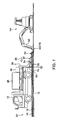
- a 10-ton capacity dump truck 18 is driven onto the asphalt concrete layer 16.
- a forward traveling direction of the dump truck 18 corresponds to a peeling direction 20 of the asphalt pavement 22.
- the present invention is intended to peel off the asphalt pavement 22 from the steel plate 12 and extract the peeled asphalt pavement 22 in the form of an asphalt block 24, wherein the peeling direction 20, and a horizontal direction orthogonal to the peeling direction, will hereinafter be referred to respectively as “longitudinal direction” and “lateral direction”. Further, as shown in FIG. 7(C) , a longitudinal length of the asphalt block 24, and a lateral length of the asphalt block 24, will hereinafter be referred to respectively as “asphalt block length L 1 " and "asphalt block width L 2 ".
- a cut line 72 is pre-formed in the asphalt pavement 22 using a cutting blade (not shown) to segment the asphalt pavement 22 by a given asphalt block width L 2 .
- a cutting blade (not shown) to segment the asphalt pavement 22 by a given asphalt block width L 2 .
- one lane of a road has a width of about 3,500 mm.
- the asphalt block width L 2 and the asphalt block length L 1 may be set, respectively, in the range of 1,000 to 1,800 mm and in the range of 600 to 1,200 mm, and the cut line 72 may be formed to segment the asphalt pavement 22 into two or three parts.
- FIG. 7(A) shows one example where the asphalt pavement 22 is segmented into three lanes 30A, 30B, 30C.
- the cut line 72 to be formed using the cutting blade is not required to have a depth reaching the steel plate 12, but it may have a depth which is about 80% of a thickness of the asphalt pavement 22. This makes it possible to prevent the steel plate 12 from being scratched.
- the cutting blade may be any type as long as it can form the cut line 72 in the asphalt pavement 22. For example, a disc saw having rotary saw teeth, or a pressing/cutting blade adapted to cut into an asphalt pavement while melting asphalt, may be used.
- a coil unit 32 is placed on an upper surface of the asphalt concrete layer 16 at a position on the trailing side relative to the dump truck 18.
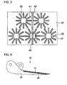
- three electromagnetic induction coils 36 are provided in a trailing region inside a box-shaped frame member 34 made of FRP, and arranged in side-by-side relation to each other at even intervals in the lateral direction, and two electromagnetic induction coils 36 are provided in a leading region inside the box-shaped frame member 34, and arranged in side-by-side relation to each other in the lateral direction while being offset relative to the arrangement of the trailing-side electromagnetic induction coils 36 by a distance approximately equal to one-half of a width of one of the trailing-side electromagnetic induction coils 36.
- each of the electromagnetic induction coils 36 is fixed onto a bottom plate 34A of the frame member 34.
- the bottom plate 34A of the frame member 34 also serves as a cover member for the electromagnetic induction coils 36 to prevent damage of the electromagnetic induction coils 36 during use.
- a holding member for five assemblies of a ferrite member 38 and the electromagnetic induction coil 36 may be provided on a lower surface of a horizontal plate bridged between opposed inner walls of the frame member 24 to allow the respective assemblies of the ferrite member 38 and the electromagnetic induction coil 36 to be fixed thereto.
- the ferrite member 38 is placed on an upper surface of the electromagnetic induction coil 36 in a radial pattern relative to a center of the electromagnetic induction coil 36.
- the ferrite member in the first embodiment is formed and arranged to partially cover the upper surface of the electromagnetic induction coil 36, it may be formed and arranged to partially cover at least one of the upper surface, an inner peripheral surface and an outer peripheral surface of the electromagnetic induction coil 36, or may be formed and arranged to entirely cover at least one of the upper surface, the inner peripheral surface and the outer peripheral surface of the electromagnetic induction coil 36.
- the frame member 34 has a board 40 formed to have a thickness approximately equal to that of the ferrite member 38 and provided at a vertically intermediate position thereof to extend approximately in a horizontal direction, as shown in a top plan view thereof in FIG. 3 .
- the board 40 is formed with five groups of cutouts 41 for restricting a horizontal displacement of the respective ferrite members 38.
- a lower surface of each of the electromagnetic induction coils 36 is disposed in adjacent relation to the upper surface of the asphalt concrete layer 16 as close as possible to reduce a distance between an upper surface of the steel plate 12 and the lower surface of the electromagnetic induction coil 36.
- a distance H between the upper surface of the steel plate 12 and the lower surface of the electromagnetic induction coil 36 is set at 100 mm. That is, a gap of 25 mm exists between the upper surface of the asphalt concrete layer 16 and the lower surface of the electromagnetic induction coil 36.
- the frame member 34 has a detachable top plate 34B made of FRP. This makes it possible to prevent an operator or the like from touching the electromagnetic induction coils 36 when they are is in a high-temperature state, and promote heat release to an outside of the frame member 34.
- the top plate 34B can be detached to facilitate a maintenance operation for the electromagnetic induction coils 36.
- the coil unit 32 is adapted to allow a plurality of the coil units 32 to be connected to each other in the lateral direction.
- the frame member 34 may be made of any other suitable material having thermal insulation properties and capable of ensuring sufficient stiffness as a box-shaped body to install the assemblies of the ferrite member 38 and the electromagnetic induction coil 36, such as a synthetic resin panel material.
- the stiffness of the frame member 34 is further increased using a plurality of reinforcements 43, 45.
- the top plate 34B of the frame member 34B is made of a material having thermal insulation properties and high thermal conductivity. In FIG. 2(B) , the top plate 34A, the board 40 and the reinforcements 43, 45 are omitted for convenience of explanation.
- a high-frequency power generating unit 46 for supplying a high-frequency power to the electromagnetic induction coils 36 via an electric cable 58, and a power generator 48 serving as a power source of the high-frequency power generating unit 46, are mounted on a loading platform of the dump truck 18.
- a supporting column 50 is fixed to an rear end of the loading platform of the dump truck 18 to protrude downwardly, and a connection portion 52 provided in the vicinity of a lower end of the supporting column 50 is coupled to a connection portion 54 provided on a leading side of the coil unit 32, through a pulling wire 56.
- a small turning-type backhoe 64 having an arm 62 and a ripper 60 attached to a distal end of the arm 62 to serve as a peeling member is driven onto the steel plate 12 at a position on the trailing side relative to the coil unit 32.
- the ripper 60 comprises a wedge-shaped thermally-conductive base member 66, and a sharp-pointed claw member 68 made of iron and attached onto an upper surface of the base member 66 in a replaceable manner. Further, a Teflon (TM) coating 70 is formed on an upper surface of the claw member 68.
- the ripper 60 is formed to have a lateral width less than the asphalt block width L 2 .
- the wedge-shaped thermally-conductive base member 66 may be made of a material which allows heat of a lower surface of the asphalt pavement 22 in a melted state to be released through the base member 66, and has strength and durability necessary for an operation of peeling off the asphalt pavement 22.
- the base member 66 is made of a steel material.
- the Teflon (TM) coating 70 has wear resistance and heat resistance, and therefore can ensure long-term use of the ripper 60. Further, the claw member 68 is replaceable. Thus, even if a tip of the claw member 68 is rounded off due to a long-term peeling operation, or the Teflon (TM) coating 70 is peeled off, the claw member 68 can be replaced with new one. Alternatively, the claw member 68 may be detached to re-shape the tip or re-form a new Teflon (TM) coating 70, and reused.
- the cut line 22 is formed in the asphalt pavement 22 using the cutting blade to segment the asphalt pavement 22 by the asphalt block width L 2 .
- the asphalt pavement 22 is segmented into three lanes 30A, 30B, 30C.
- the coil unit 32 is placed on each of two zones B, C of the segmental asphalt pavements 22 to be initially peeled off.
- the coil unit 32 is provided in a member of two, wherein the two coil units 32 are connected to each other in the lateral direction, and pulled by the dump truck 18 provided in a number of one.
- a lower surface of the gussasphalt layer 14 in contact with the heated steel plate 12 is melted to form a melted layer 74 therein.
- the high-frequency power to be supplied to the electromagnetic induction coils 36 is adjusted to allow the steel plate 12 to be heated up to a temperature causing melting of only the lower surface of the gussasphalt layer 14.
- the lower surface of the gussasphalt layer 14 is not adequately peeled off. If the temperature of the steel plate 12 is excessively greater than a melting point of the lower surface of the gussasphalt layer 14, the segmental asphalt pavement 22 is entirely softened to preclude handling in the form of a block, and the steel plate is likely to be deformed.
- Gussasphalt is generally melted at about 80°C.
- the high-frequency power is preferably supplied to the electromagnetic induction coils 36 to allow the steel plate 12 to be heated up to a temperature slightly greater than 80°C.
- the dump truck 18 In conjunction with initiation of the heating, the dump truck 18 is moved in the forward traveling direction to pull each of the coil units 32 so as to gradually move the coil unit 32 in the peeling direction 20.
- a moving speed of the coil unit 32 is appropriately determined depending on a heating capability of the coil unit 32 and a desired speed of the peeling operation.
- the electromagnetic induction coils 36 are arranged in side-by-side relation to each other at even intervals in the lateral direction.
- a surface of the steel plate 12 corresponding to the zones B, C can be entirely heated.
- the leading-side two electromagnetic induction coils 36 are arranged in side-by-side relation to each other in the lateral direction while being offset relative to the arrangement of the trailing-side electromagnetic induction coils 36 by a distance approximately equal to one-half of a width of one of the trailing-side electromagnetic induction coils 36.
- portions of the steel plate 12 which have not been able to be sufficiently heated by the leading-side two electromagnetic induction coils 36 can be subsequently heated by the trailing-side electromagnetic induction coils 36, so that the surface of the steel plate 12 corresponding to the zones B, C can be evenly heated.
- each of the electromagnetic induction coils 36 is covered by the ferrite member 38.
- a magnetic circuit resistance around the electromagnetic induction coil 36 can be reduced to allow an eddy current to be efficiently produced in the steel plate 12.
- the ripper 60 is inserted into the melted layer 74 of the lower surface of the gussasphalt layer 14 in the zone B to peel off the segmental asphalt pavement 22 from the steel plate 12.
- the melted layer 74 is locally heated for a relatively short period of time, and therefore the entire amount of heat is relatively small.
- the thermally-conductive ripper 60 it will be is cooled down to a temperature causing no re-bonding (in gussasphalt, the temperature is generally about 70°C), within a relatively short period of time.
- the ripper 60 has the Teflon (TM) coating 70 formed on the upper surface thereof.
- anti-drop-off means such as a device adapted to clamp the asphalt block 24 from respective sides of upper and lower surfaces thereof, is provided in view of operation efficiency and safety.
- the asphalt block 24 is slowly dropped onto and temporarily stored on an upper surface of the lane 30C.
- the temporarily-stored asphalt block 24 is loaded into a dump truck or other transportation means using a loading machine which is provided separately. This loading operation is continuously performed in conjunction with the peeling operation.
- the ripper 60 is inserted into the melted layer 74 of a lower surface of the gussasphalt layer 14 in the zone C heated by the electromagnetic induction coils 36 located above the lane 30B, to peel off the segmental asphalt pavement 22 from the steel plate 12. Then, the aforementioned process in FIGS. 5(A) to 5(C) is repeated to alternately peel off the two segmental asphalt pavements 22 in the lanes 30A, 30B. Specifically, as shown in FIGS.
- An object to be heated by the electromagnetic induction coils 36 is the steel plate 12, and therefore the heating can be efficiently performed.
- an amount of heat to be applied can be set at a value for melting only the lower surface of the gussasphalt layer 14.
- the asphalt pavement 22 can be peeled with a relatively small amount of electric power.
- the peeled asphalt pavement 22 is not entirely softened, and the lower surface of the gussasphalt layer 14 is also cooled down to a temperature causing no re-bonding, within a relatively short period of time, by coming into contact with the upper surface of the ripper 60.
- the Teflon (TM) coating 70 can prevent the lower surface of the gussasphalt layer 14 from being bonded onto the ripper 60 during temperature reduction of the lower surface.
- the peeled asphalt pavement 22 can be handled in the form of the asphalt block 24 to facilitate the asphalt-pavement removing operation and other operation to achieve enhanced operation efficiency.
- the asphalt block 24 is temporarily stored on the upper surface of the asphalt pavement strip 30C.
- the asphalt block 24 may be temporarily stored in a position on the trailing side relative to the backhoe 64 by turning the arm 62 of the backhoe 64 180 degrees.
- the Teflon (TM) coating 70 is employed as a peeling layer to be formed on the upper surface of the claw member 68.
- the peeling layer may be made of any other suitable material capable of preventing the lower surface of the gussasphalt layer 14 from being bonded onto the ripper 60, such as polyimide resin, polyphenylene sulfide (PPS), modified fluororesin, nylon, polyethylene, vinyl chloride, Teflon (TM) resin, or engineering plastic, e.g., Duracon (TM) or MC nylon, or may be a composite material sheet comprising the above resin and fiber, such as glass fiber, carbon fiber or aramid fiber.
- the above resin has wear resistance and heat resistance, and therefor can ensure long-term use of the ripper 60.
- a melting temperature of gussasphalt is about 80°C.
- heat resistance a material resistant to a temperature of up to about 120°C may be used. It is more preferable to use Teflon (TM) excellent in wear resistance and heat resistance.
- an oil such as light oil or NEPPARAN (TM)
- NEPPARAN is an anti-bonding agent against asphalt mixtures, and can exhibit higher debondability than that of light oil.
- NEPPARAN-W comprises a mineral resin, a surfactant and clean water
- NEPPARAN-ECO-W comprises a plant oil, a surfactant, a water-soluble solvent, an oil-soluble solvent and clean water.
- the ripper 60 may be formed in a comb-like configuration to more reliably prevent bonding of the melted lower surface of the gussasphalt layer 14 onto the ripper 60.
- the second embodiment is based on a system in which the Teflon (TM) coating 70 is not formed on the upper surface of the claw member 68 attached onto the upper surface of the base member 66 of the ripper 60 in the first embodiment.
- TM Teflon
- a ripper 76 comprises a wedge-shaped thermally-conductive base member 66 made of a steel material, and a sharp-pointed claw member 68 made of iron and attached onto an upper surface of the base member 66 in a replaceable manner.
- the ripper 76 is formed to have a lateral width less than the asphalt block width L 2 .
- the claw member 68 is replaceable. Thus, even if a tip of the claw member 68 is rounded off due to a long-term peeling operation, the claw member 68 can be replaced with new one. Alternatively, the claw member 68 may be detached to re-shape the tip, and reused.
- a heater 78 serving as separating means is incorporated into the base member 66.
- the heater 78 is adapted to instantaneously heat the claw member 68 in response to an electric power supplied from an electric double-layer capacitor.
- an asphalt pavement 22 is peeled off from a steel plate 12, and extracted, according the process in FIGS. 5(A) to 5(C) , in the same manner as that in the first embodiment. However, when a temperature of a lower surface of an asphalt block 24 is lowered in the state illustrated in FIG. 5(C) , the lower surface of the asphalt block 24 is bonded onto the ripper 76.
- the claw member 68 is instantaneously heated by the heater 78 to reduce a bonding force between the lower surface of the asphalt block 24 and an upper surface of the claw member 68, and separate the asphalt block 24 from the ripper 76.
- the asphalt block 24 is temporarily stored, for example, on a square timber or a sheet having a surface subjected to a treatment for preventing bonding of melted asphalt.
- the second embodiment can obtain approximately the same effects as those in the first embodiment.
- the bonding of the asphalt block 24 onto the ripper 76 and the separation of the asphalt block 24 from the ripper 76 can be controlled to prevent drop-off of the asphalt block 24 from the ripper 76 during the asphalt-pavement removing operation and other operation.
- the claw member 68 is heated using the heater 78 to separate the asphalt block 24 from the ripper 76.
- any other suitable heating means capable of reducing the bonding force between the lower surface of the asphalt block 24 and the upper surface of the claw member 68 may be used.
- the electric double-layer capacitor used as a power source makes it possible to instantaneously heat the claw member 68 so as to quickly complete the separation.
- the separation may be achieved by mechanically pushing out the asphalt block 24 using a piezoelectric device provided on the upper surface of the claw member 68, or a push-out mechanism comprising a hydraulic jack or an electric motor.
- the piezoelectric device is excellent in operational response and energy efficiency. If a push-out stroke is insufficient, the piezoelectric device may be used in a multiple structure.
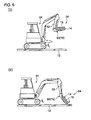
- the second embodiment is based on a system in which the same peeling member as the ripper 60 in the first embodiment is provided at a leading end of a self-propelled carriage 80.
- the same element or component as that in the first embodiment is defined by the common reference numeral or code, and its description will be omitted on a case-by-case basis.
- a carriage 80 having a chevron-shaped low-gradient upper surface is driven onto a steel plate 12.
- the carriage 80 is provided with a caterpillar (TM) 84 powered by electricity or an internal combustion engine.
- the caterpillar (TM) 84 is made of rubber to sufficiently obtain a reaction force in a horizontal direction during an after-mentioned operation of inserting a ripper 82 into a melted layer 74.
- the ripper 82 is provided at a leading end of the carriage 80.
- the ripper 82 comprises a base member 86, a claw member 88 and a Teflon (TM) coating 90 each made of the same material as that of the ripper 60 in the first embodiment, wherein a lateral width of the ripper 82 is set to be less than the asphalt block width L 2 .
- TM Teflon
- a tip of the ripper 82 can be moved in an upward-downward direction by stretching and retracting motions of a hydraulic cylinder 96. This allows the ripper 82 to be inserted into an adequate position of the melted layer 74. In addition, the tip of the ripper 82 can be set at a lifted position during a traveling operation other than a peeling operation, to prevent the ripper 82 from hindering traveling of the carriage 80.
- the carriage 80 includes a belt conveyer 92 which is disposed to extend along the chevron-shaped upper surface thereof, and adapted to be moved in a direction indicated by the arrow 94 so as to transfer an asphalt block 24 in a rightward direction in FIG. 9 .
- one coil unit 32 is placed on a zone B of a segmental asphalt pavement 22 to be firstly peeled off, and pulled by one dump truck 18. That is, the peeling operation is performed on a strip-by-strip basis.
- the ripper 60 When the lower surface of the gussasphalt layer 14 comes into contact with an upper surface of the thermally-conductive ripper 82, it will be is cooled down to a temperature causing no re-bonding (in gussasphalt, the temperature is generally about 70°C), within a relatively short period of time. Further, the ripper 60 has the Teflon (TM) coating 90 formed on the upper surface thereof. Thus, when a temperature of a lower surface of the gussasphalt layer 14 is lowered, the lower surface of the gussasphalt layer 14 is not bonded onto the ripper 82.
- TM Teflon
- the peeled asphalt pavement 22 is moved obliquely upwardly along the gradient of the upper surface of the ripper 82.
- an upper surface of the peeled asphalt pavement 22 is bent in a region directly above the tip of the ripper 82 to create a crack at a position around the tip of the ripper 82.
- the extracted asphalt blocks 24 are transferred in the rightward direction by the belt conveyer 92, and sequentially placed on the steel plate 12 at a position on a trailing side relative to the carriage 80.
- Each of the upper surface of the carriage 80 and the belt conveyer 92 has a gentle falling gradient, and therefore each of the extracted asphalt blocks 24 can be gently placed on the steel plate 12
- the third embodiment can obtain approximately the same effects as those in the first embodiment.
- the asphalt blocks 22 are temporality stored on the steel plate 12 at the position on the trailing side relative to the carriage 80, as shown in FIG. 9 .
- an operation of loading the asphalt blocks 24 into a dump truck or other transportation means can be performed after completion of the peeling operation.
- the carriage 80 may be provided for each of three asphalt pavement strips 30A, 30B, 30C to simultaneously perform the peeling operation therefor.
- the peeled asphalt pavement 22 is fragmented by pulling it in the direction indicated by the arrow 98, using the belt conveyer 92.
- the peeled asphalt pavement 22 may be fragmented by lifting the tip of the ripper 82 upwardly, as shown in FIG. 10 .
- Each of the carriage 80 and the ripper 82 may be designed to variously change a lateral width thereof so as to cope with various asphalt block widths L 2 .
- the traveling of the carriage 80 based on the caterpillar (TM) 84 may be manually manipulated using a control box provided in the carriage 80, or may be remotely manipulated. Further, the carriage 80 may be a wheelie type, wherein the carriage 80 may be pulled by the dump truck 18.
- the fourth embodiment is based on a system in which the cutting blade, the coil unit 32 and the ripper 60 in the first embodiment are integrally provided in a single vehicle.
- the same element or component as that in the first embodiment is defined by the common reference numeral or code, and its description will be omitted on a case-by-case basis.
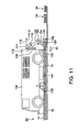
- a van-type vehicle 100 is driven onto an asphalt concrete layer 16 of an asphalt pavement 22 provided on a steel plate 12.
- the vehicle 100 is equipped with a high-frequency power generating unit 46 and a power generator 48.
- the vehicle 100 has a disc saw-type cutting blade 102 provided at a center thereof and adapted to form a cut line 72 in the asphalt pavement 22.
- the cutting blade 102 is provided in a lower portion of a vehicle body of the vehicle 100, and adapted to be moved in an upward-downward direction so as to adjust a depth of the cut line 72.
- the vehicle 100 also has a coil unit 104 fixed to a lower surface of a chassis thereof at a position on a trailing side relative to the cutting blade 102.
- the coil unit 104 is the same as that the coil unit 32 in the first embodiment, except that the coil unit 104 is devoid of the wheels 44.
- the vehicle 100 further has a cutting blade 106 provided at a rear end of the vehicle body to protrude downwardly in such a manner that a tip of the cutting blade 106 is located in adjacent relation to an upper surface of the asphalt concrete layer 16.
- the vehicle 100 further has a support member 108 provided on an upper side of the rear end the vehicle body to protrude from the vehicle body in a trailing direction, and adapted to be moved in an upward-downward direction indicated by the arrows 112, 114.
- the support member 108 is also adapted to be stretched and retracted in a leading-trailing direction indicated by the arrows 116, 118 to allow a pin 110 provided at a trailing end of the support member 108 to be moved in the leading-trailing direction
- An upper end of an arm member 120 is rotatably connected to the trailing end of the support member 108 through the pin 110.
- the arm member 120 is adapted to be swingably moved in directions indicated by the arrows 122, 124 by a driving unit (not shown).
- a ripper 126 is attached to a lower end of the arm member 120.
- the ripper 126 comprises a wedge-shaped thermally-conductive base member 128 made of a steel material, a claw member 68 made of iron and attached onto an upper surface of the base member 128, and a Teflon (TM) coating 70 formed on an upper surface of the claw member 68.
- the ripper 60 is formed to have a lateral width less than the asphalt block width L 2 , as with the ripper 60 in the first embodiment.
- the ripper 126 is formed to have a lateral width less than the asphalt block width L 2 .
- the claw member 68 is attached to the arm member 120 in such a manner that a tip thereof is oriented toward the vehicle body. Thus, according to the swing movement in the direction indicated by the allow 122, the ripper 126 can be inserted into a melted layer of a lower surface of a gussasphalt layer 14.
- the cut line 72 is formed in the asphalt pavement 22 to segment the asphalt pavement 22 by the asphalt block width L 2 .
- the arm is swingably moved in the direction indicated by the arrow 120 to insert the ripper 126 into the melted layer 74 so as to peel off the segmental asphalt pavement 22 from the steel plate 12.
- An adjustment of an insertion position in an upward-downward direction is performed by moving the support member 108 in the upward-downward direction.
- the support member 108 is stretched in the direction indicated by the arrow 118 to move the ripper 126 in a training direction while maintaining the ripper 126 in a posture for lifting up the asphalt block 24.
- the arm 120 is swingably moved in the direction indicated by the arrow 124 to gently place the asphalt block 24 on the steel plate 12.
- the fourth embodiment can obtain approximately the same effects as those in the first embodiment.
- all the devices or components can be integrated together, as shown in FIG. 11 , to achieve excellent mobility.
- the ripper 126 is designed to have the same structure as that of the ripper 60 in the first embodiment.
- the ripper 126 may be designed to have the same structure as that of the ripper 76 in the second embodiment.
- each of the base members 66, 86, 128 of the rippers 60, 76, 82, 126 is formed as a thermally-conductive member.
- Each of the base members may be made of a material having higher thermal conductivity.
- a cooling fin or a cooling fan may be provided on the side of a back surface of the ripper to quickly cool the melted lower surface of the asphalt block 24 so as to increase a speed of the peeling operation
- the claw member (68, 88) is made of iron.
- any other suitable material which has heat resistance, thermal conductivity, and hardness capable of preventing the tip of the claw member from being rounded, may be used.
- the ripper (60, 76, 82, 126) is formed in a wedge shape.
- any other suitable shape having at least a sharp tip may be used.
- a ripper 130 having a cutting blade shape only in a tip portion although a body has an even thickness may be used.
- the ripper may be designed to vibrate the tip of the claw member (68, 88). In this case, vibration in an upward-downward direction is likely to cause damage of the steel plate or generation of noise.
- the ripper is preferably designed to vibrate the tip in a horizontal direction.
- An inclination of the upper surface of the ripper may be increased to facilitate creation of a crack in the segmental asphalt pavement 22 when the ripper is inserted into the melted layer 74. Further, in the operation of fragmenting the peeled asphalt pavement 22, a wedge-shaped cutting blade may be pressed from above, or a cut line may be pre-formed by the cutting blade.
- Specifications (e.g., a sectional diameter of a conductor of the coil, a diameter of the coil and the number of turns in the coil) of the electromagnetic induction coil 36 may be determined depending on a thickness of a target asphalt pavement (a distance between the upper surface of the steel plate 12 and the lower surface of the electromagnetic induction coil 36) and a melting temperature of a lower surface of the target asphalt pavement.
- a sectional diameter of a conductor of the coil, a diameter of the coil and/or the number of turns in the coil may be increased to provide enhanced heating capability of the electromagnetic induction coil 36 relative to the steel plate 12.
- a litz wire may be used as the coil conductor, or a device for cooling the electromagnetic induction coil 36 may be provided, to provide enhanced heating capability.
- a mechanism for adjusting an installation height of the electromagnetic induction coil 36 may be provided in the coil unit (32, 104). In this case, the installation height of the electromagnetic induction coil 36 can be changed to adjust the heating capability relative to the steel plate 12.
- the coil unit 32 is pulled by the dump truck 18.
- the coil unit 32 is pulled using any type of vehicle other than the dump truck.
- the coil unit 32 may be designed as a self-propelled type, or the coil unit 32 may be attached to a lower surface of a chassis of the dump truck 18.
- a device for reciprocatingly moving the electromagnetic induction coil 36 within the coil unit (32, 104) in the lateral direction on a periodic basis may be provided, and the number of electromagnetic induction coils 36 may be reduced. This makes it possible to cope with various asphalt block widths L 2 in an easy manner.
- the two coil units 32 are connected to each other in the lateral direction to allow the two zones B, C of the segmental asphalt pavements 22 to be simultaneously heated.
- the two coil units 32 may be connected in offset relation to each other in the peeling direction 20 to pull the two coil units 32 by the dump truck 18 in such a manner as to move the coil unit 32 for the zone B in a leading manner relative to the coil unit 32 for the zone C.
- the ripper 60, 76
- a combination of the dump truck 18 and the coil unit 32 may be arranged on each of the lanes 30A, 30B in such a manner as to pull the coil unit 32 by the corresponding dump truck 18.
- the width of the ripper (60, 76, 82, 126) is set to be less than the asphalt block width L 2 .
- the width of the ripper is variable.
- the present invention is not limited thereto, but may be applied to any other suitable type of vehicle having a turnable arm allowing the ripper (60, 76) to be attached thereto.
- a gussasphalt layer 14 having a thickness of 35 mm and an asphalt concrete layer 16 having a thickness of 40 mm, which are made up of an asphalt pavement 22, are laminated on a steel plate 12 serving as an upper member of a steel plate deck of a bridge and having a thickness of 12 mm, in this order, to form an asphalt pavement 22, as with the first embodiment.
- a 10-ton capacity dump truck 254 serving as a transportation vehicle is driven onto the asphalt concrete layer 16. Specifically, the dump truck 254 is arranged on a leading side relative to a position for extracting an after-mentioned asphalt block 256, in a forward traveling direction of the dump truck 254.
- the forward traveling direction of the dump truck 254 corresponds to a progress direction 252 of an operation of the asphalt pavement removing system 250.
- a horizontal direction orthogonal to the progress direction 252 will hereinafter be referred to as "road width direction”.
- a length of an asphalt block 256 to be extracted as a plate-shaped rectangular block, in the progress direction 252, and a length of the asphalt block 256 in the road width direction will hereinafter be referred to respectively as “asphalt block length S 1 " and "asphalt block width S 2 ".
- a first cut line 258 parallel to the progress direction 252 is formed in the asphalt pavement 22 using a cutting blade 262 of a cut-line forming device as a first cut-line forming device to segment the asphalt pavement 22 by a given width (asphalt block width S 2 ).
- the cut-line forming device 260 is disposed on a leading side relative to a caterpillar (TM)-type traveling carriage 264 placed on the asphalt pavement 22 at a position on a training side relative to the dump truck 254
- TM caterpillar
- a rail member 268 is hung from a distal end of a support member 266 protruding from a front end of the traveling carriage 264.
- the rail member 268 is disposed to extend in the road width direction.
- a movable member 270 is provided in such as manner as to be moved along the rail member 268.
- An arm member 272 is disposed to penetrate through the movable member 270, and adapted to be selectively moved toward leading and trailing sides of the progress direction by a driving unit (not shown).
- the cut-line forming device 260 and a measurement device 274 operable to measuring a thickness of the asphalt pavement 22 are fixed to opposite ends of the arm member 272, respectively.
- the measurement device 274 is disposed on the leading side of the progress direction 252, and the cut-line forming device 260 is disposed on the trailing side of the progress direction 252. That is, in conjunction with the movement of the arm member 272 toward the leading or trailing sides, the measurement device 274 and the cut-line forming device 260 are simultaneously moved toward the leading or trailing sides.
- the measurement device 274 is adapted to be moved in an upward-downward direction so as to adjust a height position thereof.
- the cut-line forming device 260 is adapted to be moved in an upward-downward direction so as to adjust a cut depth of the cutting blade 262 thereof.
- the arm member 272 is firstly moved relative to the movable member 270 toward the trailing side of the progress direction 252 to allow the cut-line forming device 260 to reach a trailingmost position relative to the movable member 270.
- the cut-line forming device 260 is moved to an upper position where the cutting blade 262 is not in contact with the asphalt pavement 22.
- FIG. 18(A) shows a state after the first cut line 258 has already formed to a position directly below the cut-line forming device 260
- the cut-line forming device 260 is moved downwardly while rotating the cutting blade 262 thereof, so that the asphalt pavement 22 is cut by the cutting blade 262 to form the first cut line 258.
- the height position of the cut-line forming device 260 is adjusted based on a thickness of the asphalt pavement 22 measured by the measurement device 274.
- the arm member 272 is moved relative to the movable member 270 toward the leading side of the given direction 252 while continuing the cutting of the asphalt pavement 22 by the cutting blade 262, to form the first cut line in a leading region of the asphalt pavement 22.
- the height position of the cut-line forming device 260 is continuously adjusted based on a thickness of the asphalt pavement 22 measured by the measurement device 274, in such a manner as to allow the first cut line 258 formed using the cutting blade 262 to have a depth which approximates to a distance to the steel plate 12 or an appendage provided on the steel plate 12 as close as possible and fails to reach the steel plate 12 or the appendage.
- the cut-line forming device 260 is moved to reach a leadingmost position relative to the movable member 270.
- the measurement device 274 may be any type capable of sensing metal and measure a distance to the metal.
- An electromagnetic induction-type measurement device is suitable as the measurement device 274.
- an electromagnetic wave-type measurement device there is a concern about false measurement due to reflection of an electromagnetic wave at a position, such as a position of drainage pavement containing water, causing a rapid change in permittivity.
- the electromagnetic induction-type measurement device based on sensing of metal can prevent such false measurement.
- the depth of the first cut line 258 formed using the cutting blade 262 is set at a value which approximates to a distance to the steel plate 12 or an appendage provided on the steel plate 12 as close as possible and fails to reach the steel plate 12 or the appendage.
- the depth of the first cut line 258 may be set at a value which fails to reach the steel plate 12 or an appendage provided on the steel plate 12.
- an after-mentioned operation of fragmenting and extracting the segmental asphalt pavement 22 in the form of an asphalt block 256 is more facilitated by setting the depth of the first cut line 258 at a value which approximates to a distance to the steel plate 12 or an appendage provided on the steel plate 12 as close as possible.
- the first cut line 258 may be formed to have a constant depth from an upper surface of the asphalt pavement 22.
- the constant depth is set based on a position slightly shallower than a depth reaching a head of a bolt 278 located at the shallowest position
- the first cut line 258 is preferably formed to leave the segmental asphalt pavement 22 by a thickness of about 20 mm from an upper surface of the steel plate 12.
- the cut-line forming device 260 may be any type capable of forming the first cut line 258 in the asphalt pavement 22.
- a pushing and cutting blade may be used as well as the cutting blade 262, such as a diamond cutter.
- one lane of a road has a width of about 3,500 mm.
- the asphalt block width L 2 and the asphalt block length L 1 may be set, respectively, in the range of 1,000 to 1,800 mm and in the range of 600 to 1,200 mm, and the first cut line 258 may be formed to segment the asphalt pavement 22 into two or three parts.
- FIG. 17(A) shows one example where the asphalt pavement 22 is segmented into three parts.
- the number and arrangement of cut-line forming devices 260 may be determined depending on the number of first cut lines 258 (the number of division of the asphalt pavement 22 in the road width direction).
- the same coil unit 32 as that in the first embodiment is placed on an upper surface of the asphalt concrete layer 16 at a position on the trailing side relative the traveling carriage 264.
- the coil unit 32 serves as an electromagnetic induction coil unit as a softened-layer forming device.
- the coil unit 32 is operable to subject the steel plate 12 to electromagnetic induction heating so as to form, in the asphalt pavement 22, a softened layer having a lower in contact with the steel plate 12.
- the coil unit 32 comprises a first coil group consisting of two electromagnetic induction coils 36 arranged in side-by-side relation to each other, a second coil group consisting of three electromagnetic induction coils 36 arranged in side-by-side relation to each other, and a frame member 34 adapted to allow the first and second coil groups to be fixed thereto.
- the electromagnetic induction coils 36 in the first coil group are disposed on the leading side of the progress direction 252 (in FIG. 2(B) , the peeling direction 20) and arranged in side-by-side relation to each other in a direction intersecting the progress direction 252.
- the electromagnetic induction coils 36 in the second coil group are disposed on the opposite side relative to the first coil group with respect to the progress direction 252 and arranged in side-by-side relation to each other in a direction intersecting the progress direction 252.
- the first coil group is disposed in the frame member 34 in offset relation to the second coil group, in such a manner that a center of each of the electromagnetic induction coils 36 in the first coil group is located between respective centers of adjacent ones of electromagnetic induction coils 36 in the second coil groups.
- the electromagnetic induction coils 36 in each of the first and second coil groups are arranged in side-by-side relation to each other. This makes it possible to heat the entire surface of a portion of the steel plate 12 located directly below the coil unit 32.
- the first coil group is disposed in the frame member 34 in offset relation to the second coil group, in such a manner that a center of each of the electromagnetic induction coils 36 in the first coil group is located between respective centers of adjacent ones of the electromagnetic induction coils 36 in the second coil group.
- portions of the steel plate 12 which have not been able to be sufficiently heated by the electromagnetic induction coils 36 in the first coil group can be subsequently heated by the electromagnetic induction coils 36 in the second coil group located on the trailing side relative to the first coil group, so that the entire surface of the steel plate 12 can be evenly heated.
- the number of the electromagnetic induction coils 36 in the second coil group located on the trailing side of the progress direction 252 is greater than that of the electromagnetic induction coils 36 in the first coil group located on the leading side of the progress direction 252. This makes it possible to strongly heat a larger area of the steel plate 12 until just before the asphalt pavement 22 is peeled off from the steel plate 12.
- a lower surface of each of the electromagnetic induction coils 36 is disposed in adjacent relation to the upper surface of the asphalt concrete layer 16 as close as possible to reduce a distance between the upper surface of the steel plate 12 or an appendage provided on the steel plate 12 and the lower surface of the electromagnetic induction coil 36.
- a distance H between the upper surface of the steel plate 12 and the lower surface of the electromagnetic induction coil 36 is set at 100 mm. That is, a gap of 25 mm exists between the upper surface of the asphalt concrete layer 16 and the lower surface of the electromagnetic induction coil 36.
- a high-frequency power generating unit 46 for supplying a high-frequency power to the electromagnetic induction coils 36 via an electric cable 58, and a power generator 48 serving as a power source of the high-frequency power generating unit 46, are mounted on a loading platform of the traveling carriage 264.
- Two belt conveyers 280A, 280B serving as a transfer device are disposed above the traveling carriage 264 and on the respective leading and trailing sides of the progress direction 252, and arranged in side-by-side relation to each other.
- the belt conveyers 280A, 280B are operable to transfer an extracted asphalt block 256 in a direction from a rear end to a front end of the traveling carriage 264, and load the asphalt block 256 into a loading platform of the dump truck 254. That is, the belt conveyers 280A, 280B serving as the transfer device are disposed above the coil unit 32 and the cut-line forming device 260 to transfer an extracted asphalt block 256 to a position on the leading side relative to a position R where the asphalt block 256 is extracted.
- An upper end of an actuator 282 having a lower end rotatably fixed to the front end of the traveling carriage 264 is rotatably fixed to an approximately center of a leading-side one 280A of the two belt conveyers 280A, 280B. According to stretching and retracting motions of the actuator 282, a leading portion of the belt conveyer 280A is moved in an upward-downward direction, and toward the leading and trailing sides of the progress direction to allow the asphalt block 256 to be transferred to a given position of the loading platform of the dump truck 254.
- a supporting column 284 is fixed to an rear end of the loading platform of the dump truck 18 to protrude downwardly, and a connection portion 286 provided in the vicinity of a lower end of the supporting column 284 is coupled to a connection portion 54 provided on a leading side of the coil unit 32, through a pulling wire 56.
- the clamping member 290 has a cutting blade 298 provided on a distal end thereof.
- a combination of the upper/lower-surface clamping device 292 and the backhoe 64 makes up an extraction device.
- the ripper 288 comprises a wedge-shaped thermally-conductive base member 66, a sharp-pointed claw member 68 made of iron and attached onto an upper surface of the base member 66 in a replaceable manner, and a Teflon (TM) coating 70 formed on an upper surface of the claw member 68.
- a width of the ripper 60 in the road width direction is set to be less than the asphalt block width L 2 .
- An upper portion of a support plate 294 is rotatably fixed to a distal end of the arm 62 of the backhoe 64.
- the ripper 288 has a base end fixed to a lower portion of the support plate 294.
- the clamping member has a base end rotatably fixed to an approximately central portion of the support plate 294.
- An upper end of an actuator 296 rotatably fixed to an approximately central region of an upper surface of the clamping member 290 is rotatably fixed to the upper portion of the support plate 294.
- the clamping member 290 can be opened and closed according to stretching and retracting motions of the actuator 296, in such a manner as to clamp upper and lower surfaces of an asphalt block 256 between the ripper 288 and the clamping member 290, and form a cut line in the asphalt pavement 22 by the cutting blade 298. That is, a combination of the actuator 296 and the clamping member 290 provided with the cutting blade 298 makes up a second-cut-line forming device.
- the asphalt pavement removing system 250 illustrated in FIG. 16 comprises the cut-line forming device 260, the coil unit 32 serving as a softened-layer forming device, the extraction device made up of the upper/lower-surface clamping device 292 and the backhoe 64, the belt conveyers 280A, 280B serving as a transfer device, and the dump truck 254 serving as a transportation vehicle.
- first cut line 258 parallel to the progress direction 252 are firstly formed in the asphalt pavement 22 using the cutting blade 262 of the cut-line forming device 260 as a first cut-line forming device, to segment a width of the asphalt pavement 22 into three segmental widths (three asphalt block widths S 2 ).
- the asphalt pavement 22 is segmented into three lanes 300A, 300B, 300C (the lanes 300A, 300B, 300C are arranged in a left-to-right direction when viewed in the progress direction). If respective outer edges of the lanes 300A, 300C have already been cut off, it is not necessary to form the first cut lines 258 for defining the outer edges of the lanes 300A, 300C.
- Each of the first cut lines 258 are formed through the process illustrated in FIG. 18 . Specifically, a thickness of the asphalt pavement 22 is measured using the measurement device 274 (measurement step), and the first cut line 258 is formed to have a depth less than the measured thickness of the asphalt pavement 22. Thus, the first cut line 258 has a depth which approximates to a distance to the steel plate 12 or an appendage provided on the steel plate 12 as close as possible and fails to reach the steel plate 12 or an appendage.
- the two coil units 32 connected to each other in the road width direction are placed on the segmental asphalt pavements 22 to be firstly fragmented. Both the coil units are pulled by the traveling carriage 264.
- a softened layer 302 having a lower layer in contact with the steel plate 12 heated by the electromagnetic induction heating is formed in the gussasphalt layer 14 (softened-layer forming step).
- a thickness of the softened layer 302 is appropriately determined depending properties and the thickness of the asphalt pavement 22, and the high-frequency power to be supplied to the electromagnetic induction coils 36 is adjusted to allow the softened layer 302 to have the determined thickness.
- the softened layer 302 may be formed only in the gussasphalt layer 14, or may be formed in both the gussasphalt layer 14 and the asphalt concrete layer 16. That is, the point is to form a softened layer 302 having a lower layer in contact with the steel plate 12.
- the high-frequency power to be supplied to the electromagnetic induction coils 36 may be adjusted in such a manner that a temperature of a softened layer formed in the asphalt pavement 22 is set at 55°C or more. This makes it possible to allow the softened layer 302 formed in the asphalt pavement 22 to have a viscosity suitable for peeling the asphalt pavement 22 from the steel plate 22, and a thickness of about 10 mm or more.
- the high-frequency power to be supplied to the electromagnetic induction coils 36 may be adjusted in such a manner that a temperature of a softened layer formed in the asphalt pavement 22 may be set at 80°C or more for the hot asphalt mixture, and at 96°C. or more for the hard asphalt mixture, so as to facilitate peel-off of the asphalt pavement 22 from the steel plate 12.
- the softened layer 302 is formed to extend upwardly from the upper surface of the steel plate 12 by a thickness of about 16 mm or less, and therefore most of the asphalt pavement is in a solid state.
- the segmental asphalt pavements can be fragmented and extracted in the form of an asphalt block.
- the traveling carriage 264 is moved forwardly to pull the coil units 32 so as to move the coil units 32 in the given direction by the asphalt block width S 2 .
- the heating is continuously performed while moving the coil units 32 in the progress direction 252, so that portions of the steel plate 14 which have not been able to be sufficiently heated by the electromagnetic induction coils 36 in the leading-side first coil group can be subsequently heated by the electromagnetic induction coils 36 in the trailing-side second coil group.
- the entire surface of the steel plate 12 can be evenly heated to more reliably form the softened layer 302 in each of the segmental asphalt pavements 22.
- the ripper 288 serving as a peeling member is inserted between the steel plate 302, and the softened layer formed in the gussasphalt layer 14 of the lane 300A.
- the ripper 288 may be inserted into a region of the softened layer 302 adjacent to the upper surface of the steel plate 12.
- the insertion of the ripper 288 is performed by moving the backhoe 64 forwardly or operating the arm 62.
- a mechanism for moving the ripper 288 in the leading-trailing direction may be provided in the upper/lower surface clamping device 292 to perform the insertion.
- the actuator 296 is stretched to close the clamping member 290 so as to clamp the segmental asphalt pavement 22 from the side of upper and lower surfaces thereof, using the ripper 288 and the clamping member 290.
- the cutting blade 298 provided on the distal end of the clamping member 290 presses and cuts the segmental asphalt pavement to form a second cut line intersecting the first cut line 258 (second-cut-line forming step).
- the second cut line is formed to have a depth which approximates to a distance to the steel plate 12 or an appendage provided on the steel plate 12 as close as possible and fails to reach the steel plate 12 or an appendage.
- the depth of the second cut line may be set at a value which fails to reach the steel plate 12 or an appendage provided on the steel plate 12.
- an after-mentioned operation of fragmenting and extracting the segmental asphalt pavement 22 in the form of an asphalt block 256 is more facilitated by setting the depth of the first cut line 258 at a value which approximates to a distance to the steel plate 12 or an appendage provided on the steel plate 12 as close as possible.
- the second cut line is preferably formed to extend up to a position slightly shallower than a depth reaching a head of a bolt 278 (see FIG. 18(A) ) located at the shallowest position.
- the second cut line is preferably formed to leave the segmental asphalt pavement 22 by a thickness of about 20 mm from the upper surface of the steel plate 12.
- the segmental asphalt pavement 22 has the second cut line formed by the cutting blade 298 provided on the distal end of the clamping member 290.
- the extracted asphalt block 256 is formed as a plate-shaped rectangular block.
- the asphalt block 256 unloaded onto the belt conveyer 280B in the moving step after being extracted in the extraction step is transferred in the direction from the rear end to the front end of the traveling carriage 264 by the belt conveyers 280A, 280B, and loaded into the loading platform of the dump truck 254 (transfer step). That is, an asphalt block 256 extracted in the extraction step is transferred to a position on the leading side relative to the position R where the asphalt block 256 is extracted.
- the segmental asphalt pavement 22 provided on the steel plate 12 in the lane 300A is peeled off from the steel plate 12, and removed in the form of the asphalt block 256 having a given size.
- an asphalt block 256 is removed from each of the remaining segmental asphalt pavements in the lanes 300B, 300C.
- the extraction step is performed plural times in each of the lanes 300A, 300B, 300C.
- a plurality of the second cut lines will be formed in each of the segmental asphalt pavements in the three lanes.
- FIG. 17(D) shows a state when an asphalt block 256 fragmented and extracted from the segmental asphalt pavement in the lane 300B is unloaded onto the belt conveyer 280B
- FIG. 17(E) shows a state when an asphalt block 256 fragmented and extracted from the segmental asphalt pavement in the lane 300C is unloaded onto the belt conveyer 280B.
- FIGS. 17(A) to 17(E) are repeated to remove the entire asphalt pavement 22 provided on the steel plate 12.
- the softened layer 302 formed in the segmental asphalt pavement 22 by the coil unit 32 makes it easy to peel off the segmental asphalt pavement 22 from the steel plate 12.
- the segmental asphalt pavement 22 can be fragmented without generating large vibration and noise as in the chipping technique.
- segmental asphalt pavement 22 is in a solid state.
- segmental asphalt pavement 22 can be fragmented and extracted in the form of the asphalt block 256. This makes it possible to facilitate the operation of extracting the asphalt block 256, to achieve enhanced operation efficiency.
- the asphalt block 256 can be extracted as a plate-shaped rectangular block having a given size. This makes it possible to efficiently load the asphalt block 256 into the dump truck 254 or other transportation vehicle.
- Each of the first and second cut lines is formed to have a depth failing to reach the steel plate 12 or an appendage provided on the steel plate 12. This makes it possible to prevent the steel plate 12 or the appendage provided on the steel plate 12 from being scratched.
- An object to be heated by the coil unit 32 is the steel plate 12, and therefore the heating can be efficiently performed.
- an amount of heat to be applied can be set at a value for forming the softened layer 202 in the vicinity of the steel plate 12.
- the segmental asphalt pavement 22 can be fragmented and extracted in the form of the asphalt block with a relatively small amount of electric power.
- the segmental asphalt pavement 22 is fragmented by clamping the segmental asphalt pavement 22 using the upper/lower-surface clamping device 292, and lifting the segmental asphalt pavement 22 upwardly.
- the segmental asphalt pavement 22 can be fragmented and extracted in the form of the asphalt block, i.e., the plate-shaped rectangular block, in a simple manner using a simple apparatus.
- the upper/lower-surface clamping device adapted to clamp the segmental asphalt pavement 22 from the side of the upper and lower surfaces thereof allows the segmental asphalt pavement 22 to be reliably held.
- the segmental asphalt pavement 22 can be easily peeled off from the steel plate 12 and fragmented, because a lower layer of the segmental asphalt pavement 22 is formed as a softened layer and thereby reduced in strength.
- the dump truck 254 can be arranged on the un-removed asphalt pavement to eliminate a concern about traveling thereof.
- the dump truck 254 is positioned on the leading side relative to the position R where the segmental asphalt pavement is fragmented. Thus, an operation of changing the dump truck 254 does not disturb the operation of extracting the segmental asphalt pavement 22. This makes it possible to achieve enhanced operation efficiency and enhanced safety.
- the cut-line forming device 260, the softened-layer forming device (coil unit 32), the extraction device (the upper/lower-surface clamping device 292 and the backhoe 64), the transport device (the belt conveyers 280A, 280B) and the transportation vehicle (the dump truck 254) are arranged in conformity to an operation sequence, so that the series of operations can be smoothly performed.
- the fifth embodiment has shown an example where the segmental asphalt pavement 22 is fragmented by lifting the upper/lower-surface clamping device 292 upwardly while holding the segmental asphalt pavement 22.
- a technique as shown in FIG. 20 may be employed.
- the upper/lower-surface clamping device 292 holding the segmental asphalt pavement 22 is pulled in a trailing direction. In this manner, the segmental asphalt pavement 22 is segmented and extracted in the form of the asphalt block 256.
- the second cut lines to be formed in the segmental asphalt pavement 22 is formed by the cutting blade 298 provided on the distal end of the clamping member 290 of the upper/lower-surface clamping device 292.
- the second cut lines may be formed by a technique as shown in FIG. 21 .
- an after-mentioned cut-line forming device 260 serves as the second cut-line forming device.
- the second cut line is formed in the segmental asphalt pavement 22 by a cut-line forming device 260 which is provided on the trailing side relative to the traveling carriage 264 in such a manner to form a cut line intersecting the progress direction.
- a height position of the cut-line forming device 260 is adjusted based on a value measured by the measurement device 274 as shown in FIG. 18 , in such a manner that the second cut line has a depth which approximates to a distance to the steel plate 12 or an appendage provided on the steel plate 12 as close as possible and fails to reach the steel plate 12 or an appendage.
- An asphalt pavement removing method, an asphalt pavement removing system and an electromagnetic induction coil unit, according to a sixth embodiment of the present invention, and a function and effect thereof, will be described below.
- the sixth embodiment is based on a system in which the cutting blade 298 provided on the distal end of the clamping member 290 in the fifth embodiment is substituted with a presser member, and the segmental asphalt pavement 22 is bent and fragmented.
- the same element or component as that in the fifth embodiment is defined by the common reference numeral or code, and its description will be omitted on a case-by-case basis.
- a presser member 304 is provided on a distal end of a clamping member 290 of an upper/lower-surface clamping device 292.
- the presser member 304 is an iron plate having a wedge-shaped cross-section, and arranged to extend along the road width direction of the clamping member 290.
- the sixth embodiment is different from the fifth embodiment in the process of extracting the segmental asphalt pavement 22 as shown in FIG. 19 .
- a ripper 288 is inserted between a steel plate 12 and a lower surface of a gussasphalt layer 14 of a lane A. In this operation, the ripper 288 may be inserted into a region of the softened layer 302 adjacent to an upper surface of the steel plate 12.
- an actuator 296 is stretched to close the clamping member 290 so as to clamp the segmental asphalt pavement 22 from the side of upper and lower surfaces thereof, using a ripper 288 and the clamping member 290.
- the wedge-shaped presser member 304 is brought into contact with the segmental asphalt pavement 22 in such a manner that a tip edge thereof intersects first cut lines 258 at a given lengthwise position of the segmental asphalt pavement 22.
- an upper/lower surface clamping device 292 holding the segmental asphalt pavement 22 is lifted upwardly in such a manner as to bend the segmental asphalt pavement 22 around the tip edge of the wedge-shaped presser member 304.
- the segmental asphalt pavement 22 is fragmented and extracted as an asphalt block 256, as shown in FIG. 22(C) (extraction step).
- a folding line is formed in a given position of the asphalt block 256 (the segmental asphalt pavement 22?) by the presser member 304 provided on the distal end of the clamping member 290.
- the extracted asphalt block 256 is formed as a plate-shaped rectangular block.
- the asphalt block 256 is further lifted upwardly, and unloaded onto a belt conveyer 280B provided above a traveling carriage 264 (moving step).
- the sixth embodiment can obtain substantially the same effects as those in the fifth embodiment.
- the segmental asphalt pavement 22 is bendingly lifted while being clamped by the upper/lower-surface clamping device 292.
- the segmental asphalt pavement 22 can be peeled off from the steel plate 12, and fragmented and extracted in the form of the asphalt block 256, in a simple manner using a simple apparatus.
- the need for forming the second cut lines in the segmental asphalt pavement can be eliminated. This makes it possible to prevent the steel plate 12 or an appendage provided on the steel plate 12 from being scratched due to the cut-line forming operation.
- the segmental asphalt pavement 22 can be easily bent, because the lower layer thereof is reduced in strength due to the softened layer formed therein.
- the sixth embodiment has shown an example where the member made of iron and formed to have a wedge-shaped cross-section is used as the pressure member 304.
- any other suitable member having a hardness and configuration capable of forming a folding line in the segmental asphalt pavement 22 may be used.
- the presser member may be formed in a configuration capable of being brought into contact with only a part of the entire length of the segmental asphalt pavement 22 in the road width direction at a given position thereof, instead of a configuration capable of being brought into contact with the entire length of the segmental asphalt pavement 22 in the road width direction.
- Each of the first cut line 528 and the second cut line to be formed in the asphalt pavement 22 in the fifth and sixth embodiments may be formed using an assembly of a plurality of cutting blades 306A, 306B, 306C which are superimposed on each other in such a manner that a diameter of the assembly gradually decreases in an outward direction, as shown in FIG. 23 .
- a wedge-shaped cut line can be formed. This makes it possible to facilitate the formation of the cut line and the fragmentation of the segmental asphalt pavement 22 (i.e., the segmental asphalt pavement 22 can be easily fragmented by lifting it upwardly or by pulling it in the trailing direction).
- the sixth embodiment has shown an example where the segmental asphalt pavement 22 is bent around the tip edge of the wedge-shaped presser member 304.
- the segmental asphalt pavement 22 may be bent under a condition that the second cut line has already been formed at a given lengthwise position to extend in a direction intersecting the first cut lines 258. In this case, the segmental asphalt pavement 22 can be more easily bent.
- the second cut line is formed to have a depth which approximates to a distance to the steel plate 12 or an appendage provided on the steel plate 12 as close as possible and fails to reach the steel plate 12 or an appendage.
- the depth of the second cut line is set at a value greater than one-half of a thickness of the asphalt pavement 22.
- FIG. 24 shows a state when the segmental asphalt pavement 22 is lifted upwardly while being clamped by the upper/lower-surface clamping device 292, to fragment the segmental asphalt pavement 22, after forming the wedge-shaped second cut line 318 by the technique illustrated in FIG. 23 .
- segmental asphalt pavement 22 can be peeled from the steel plate 12, and fragmented and extracted in the form of a plate-shaped rectangular block in a simple manner using a simple apparatus.
- the depth of the second cut line formed in the segmental asphalt pavement 22 is set at a value failing to reach the steel plate 12 or the appendage provided on the steel plate 12. This makes it possible to prevent the steel plate 12 or the appendage provided on the steel plate 12 from being scratched.
- the fifth and sixth embodiments have shown an example where the upper/lower-surface clamping device 292 is employed as the holding means.
- a suction device 308 and a gripping device 310 may be used.
- the suction device 308 illustrated in FIG. 25 is adapted to suck an upper surface of the segmental asphalt pavement 22 formed with the second cut lines to hold the segmental asphalt pavement 22. Then, the suction device 308 is moved upwardly to lift the segmental asphalt pavement 22 upwardly so as to fragment and extract the segmental asphalt pavement 22 in the form of the asphalt block 256.
- the gripping device 310 illustrated in FIG. 26 is provided with a claw member 314, and adapted to grip the surface of the segmental asphalt pavement 22 formed with the second cut lines by the claw member 314. Then, the gripping device 310 is moved upwardly to lift the segmental asphalt pavement 22 upwardly so as to fragment and extract the segmental asphalt pavement 22 in the form of the asphalt block 256.
- a side-surface clamping device 312 as shown in FIG. 27 may be employed as the holding means.
- the side-surface clamping device 312 is adapted to clamp the segmental asphalt pavement 22 formed with the second cut lines 320, from the side of opposed side surfaces of the segmental asphalt pavement 22, by a clamping claw 316. Then, the side-surface clamping device 312 is moved upwardly to lift the segmental asphalt pavement 22 upwardly so as to fragment and extract the segmental asphalt pavement 22 in the form of the asphalt block 256.
- the extracted asphalt block 256 is a rectangular block.
- the seconds cut lines 320 in FIGS. 25 to 27 may be formed in the same manner as that based on the cutting blade 298 provided on the distal end of the clamping member 290 of the upper/lower-surface clamping device 292 or the cut-line forming device 260 illustrated in FIGS. 21 and 23 .
- FIGS. 25 to 27 show one example where in a state after the second cut lines 320 in segmental asphalt pavement 22, the segmental asphalt pavement 22 held by the suction device 308, the gripping device 310 or the side-surface clamping device 312, is lifted upwardly to fragment the segmental asphalt pavement 22.
- the segmental asphalt pavement 22 held by the suction device 308, the gripping device 310 or the side-surface clamping device 312 may be pulled in the trailing direction, or bent, to obtain the same functions/effects as those in the fifth and sixth embodiments.
- a lower surface of the segmental asphalt pavement 22 (melted layer 302) is preferably melted.
- the fifth and sixth embodiments have shown an example where the two coil units connected to each other in the road width direction is placed on the segmental asphalt pavements 22.
- two or more coil units may be connected to each other, or all the target segmental asphalt pavements may be covered by one coil unit.
- one coil unit having a length in the road width direction less than that of the target segmental asphalt pavements may be reciprocatingly moved in the road width direction.
- Specifications e.g., a sectional diameter of a conductor of the coil, a diameter of the coil and the number of turns in the coil
- a configuration of the electromagnetic induction coil 36, and an arrangement and the number of the electromagnetic induction coils 36 may be determined depending on a distance between the upper surface of the steel plate 12 and the lower surface of the electromagnetic induction coil 36, and a heating capability required for forming the softened layer in the asphalt pavement.
- the heating of the steel plate 12 using the coil unit 32 may be intermittently performed as in the fifth and sixth embodiment, or may be continuously performed while moving the coil unit 32 in the progress direction 252.
- portions of the steel plate 12 which have not been able to be sufficiently heated by the leading-side electromagnetic induction coils 36 in the first coil group can be subsequently heated by the trailing-side electromagnetic induction coils 36 in the second coil group, so that the entire surface of the steel plate 12 can be evenly heated.
- the number of the electromagnetic induction coils 36 in the first coil group is two, and the number of the electromagnetic induction coils 36 in the second coil group is three.
- the electromagnetic induction coil 36 may be disposed in any number to obtain the same effects as those in the first to sixth embodiments.
- the number of the electromagnetic induction coils in the first coil group is two or more, and the number of the electromagnetic induction coils in the second coil group is greater than that of the electromagnetic induction coils in the first coil group by one.
- the first to sixth embodiments have shown an example where the dump truck 254 is employed as a transportation vehicle.
- any other suitable type of vehicle capable of taking in and transferring the asphalt blocks 256.
- the asphalt block 256 may be transferred to one or more of three positions on leading, lateral and trailing sides relative to the position R where the segmental asphalt block 22 is extracted.
- the fifth and sixth embodiments have shown an example where the belt conveyers 280A, 280B are employed as a transfer device.
- any other suitable transfer device capable of transferring the extracted asphalt block 256 to a loading platform of the dump truck 254 may be used.
- the extracted asphalt block 256 may be temporarily stored around the backhoe 256, and then removed separately.
- the extraction device is not limited thereto, but the holding means may be combined with any other suitable apparatus equipped with a turnable arm capable of allowing the holding means to be attached thereto.
- the fifth embodiment has shown an example where the first cut lines 258 are formed, and then the softened layer 302 is formed, whereafter the second cut lines are formed.
- the operation sequence may be changed.
- the operation sequence may be configured such that the first cut lines 258 are formed, and then the second cut lines are formed, whereafter the softened layer 303 is formed in the segmental asphalt pavement 22, or the softened layer 303 is formed in the segmental asphalt pavement 22, and then the first cut lines 258 are formed, whereafter the second cut lines are formed.
- the Teflon (TM) coating 70 serving as the peeling layer is formed on the upper surface of the claw member 68 of the ripper 288.
- any other suitable material capable of preventing bonding of the lower surface of the softened asphalt pavement onto the upper surface of the claw member 68 may be used. If there is not any risk of bonding of the lower surface of the softened asphalt pavement onto the upper surface of the claw member 68, it is not necessary to form the peeling layer on the upper surface of the claw member 68.
- an oil such as light oil or NEPPARAN (TM)
- TM NEPPARAN
- sand or the like may be spread onto the upper surface of the claw member 68, instead of the Teflon (TM) coating 70.
- the heater 78 or the piezoelectric device serving as the separation means may be incorporated into the base member 66 or provided on the upper surface of the claw member 68.
- the ripper 288 is formed in a wedge shape.
- the ripper 288 may have any other suitable shape having a sharp-pointed portion at least at a tip thereof.
- the ripper 288 may be designed to vibrate the tip of the claw member 68. In this case, vibration in an upward-downward direction is likely to cause damage of the steel plate or generation of noise. Thus, the ripper is preferably designed to vibrate the tip in a horizontal direction.
- a width of each of the ripper 288 and the clamping member 290 in the road width direction is set to be less than the asphalt block width S 2 .
- the width is variable.
- the ripper 288 may be formed in a comb-like configuration to more reliably prevent the soften layer 302 formed in the segmental asphalt pavement 22 from being bonded onto the ripper 288.
- An asphalt-pavement removing apparatus (not shown) having a single movable body mounting thereto the cut-line forming device, the softened-layer forming device, the extraction device and the transfer device, as shown in the fifth and sixth embodiments, may be developed.
- an operation of installing and removing the devices can be quickly performed to achieve high mobility.
- FIGS. 28 and 29 are a result of a heating test on an asphalt pavement (test sample 326) as shown in FIG. 30 .
- Each of the asphalt base layer 324 and the asphalt upper layer 328 is made of a hot asphalt mixture using modified asphalt (hereinafter referred to as "hot asphalt mixture") which has a softening point of 67.5°C.
- the steel plate 322 has a two-dimensional size of 90 cm x 180 cm
- the asphalt base layer 324 is provided to fully cover an upper surface of the steel plate 322.
- the asphalt upper layer 328 is provided to fully cover an upper surface of the asphalt base layer 324. That is, each of the asphalt base layer 324 and the asphalt upper layer 328 also has a two-dimensional size of 90 cm x 180 cm.
- An electromagnetic induction coil 330 is placed on an approximately central region of an upper surface of the asphalt upper layer 328 to heat the steel plate 322 by means of electromagnetic induction.
- thermocouples 332, 334, 336, 338, 340 each serving as a temperature sensor are installed in the asphalt base layer 324 and the asphalt upper layer 328 at a position immediately below an approximately center of the electromagnetic induction coil 330, and arranged along an upward direction from the upper surface in this order, so that a temperature of an installation position of each of the thermocouples is measured .
- thermocouple 332 is installed on the upper surface of the steel plate 322, and distances between the upper surface of the steel plate 322 and respective ones of the thermocouples 334, 336, 338, 340 are 9.5 mm, 19 mm, 38 mm and 76 mm. That is, the thermocouple 338 is installed on the upper surface of the asphalt base layer 324, and the thermocouple 340 is installed on the upper surface of the asphalt upper layer 328.
- FIGS. 28(A) to 28(D) and FIGS. 29(E) to 29(I) show a relationship between a temperature (horizontal axis) and a depth of the asphalt base layer 324 and the asphalt upper layer 328 (vertical axis), which is measured by the thermocouples 332, 334, 336, 338, 340.
- the points 332A, 334A, 336A, 338A, 340A in FIGS. 28(A) to 28(D) and FIGS. 29(E) to 29(I) correspond to respective measured values of the thermocouples 332, 334, 336, 338, 340.
- FIGS. 28(A) to 28(D) show respective values measured when an elapsed time from start of heating by the electromagnetic induction coil 330 is 15 (s), 30 (s), 60 (s) and 90 (s), and FIGS. 29(E) to 29(I) show respective values measured when the elapsed time from start of heating by the electromagnetic induction coil 330 is 120 (s), 150 (s), 210 (s), 270 (s) and 360 (s).
- the thickness of the asphalt pavement is 76 mm, as described above.
- FIG. 29(H) and (I) showing a state after further continuing the heating a position having a temperature of 55°C becomes shallower along with a heating time. That is, the thickness of the softened layer is increased to 10 mm or more.
- the softened layer has a softness which allows the asphalt pavement to be adequately peeled off from the steel plate, through the method according to each of the first to sixth embodiments of the present invention. Specifically, it is able to form a softened layer having a softness which allows the asphalt pavement to be peeled off from the steel plate even at a temperature of a softening point (67.5°C) or less.
- a temperature at a position on an upward side relative to the upper surface of the steel plate 322 by about 10 mm is about 55°C.
- a softened layer 302 having a viscosity suitable for peeling off the asphalt pavement 22 from the steel plate 12 and a thickness of about 10 mm or more can be formed in the asphalt pavement 22 by setting a temperature of asphalt at 55°C or more.
- a temperature of the upper surface of the steel plate 322 becomes higher along with an increase in the heating time by the electromagnetic induction coil 330.
- the asphalt pavement can be fragmented and extracted in the form of an asphalt block, specifically a plate-shaped rectangular block.
- each of the asphalt base layer 324 and the asphalt upper layer 328 was made of a hot asphalt mixture having a softening point of 67.5°C. Even when the asphalt base layer 324 is made of a hard asphalt mixture using gussasphalt (hereinafter referred to as "hard asphalt mixture", and the asphalt upper layer 328 is made of a hot asphalt mixture, a tendency of thermal conduction is substantially the same.
- the hot asphalt mixture has a softening point ranging from 55 to 75°C
- the hard asphalt mixture has a softening point ranging from 50 to 65°C.
- a softened layer having a viscosity suitable for peeling off an asphalt pavement from a steel plate can be formed in the asphalt pavement by adjusting a high-frequency power to be supplied an electromagnetic induction coil in such a manner that a temperature of the softened layer to be formed in the asphalt pavement is set at 55°C or more.
- a temperature of a softened layer is preferably set at 55°C or more while forming the softened layer at a thickness of 10 mm or more.
- a softened layer having a viscosity suitable for peeling off an asphalt pavement from a steel plate can be formed in the asphalt pavement by adjusting a high-frequency power to be supplied to an electromagnetic induction coil in such a manner that a temperature of the softened layer to be formed in the asphalt pavement is set at 55°C or more.
- a high-frequency power to be supplied to the electromagnetic induction coils 36 is adjusted in such a manner that a temperature of a softened layer to be formed in the asphalt pavement 22 is set at 80°C or more for the hot asphalt mixture and at 96°C or more for the hard asphalt mixture, so that a melted layer can be formed in a lower surface of the softened layer to facilitate peel-off of the asphalt pavement 22 from the steel plate 12.
Landscapes
- Engineering & Computer Science (AREA)
- Architecture (AREA)
- Civil Engineering (AREA)
- Structural Engineering (AREA)
- Mining & Mineral Resources (AREA)
- Road Repair (AREA)
Applications Claiming Priority (2)
| Application Number | Priority Date | Filing Date | Title |
|---|---|---|---|
| JP2006092423 | 2006-03-29 | ||
| PCT/JP2007/000312 WO2007111025A1 (ja) | 2006-03-29 | 2007-03-28 | アスファルト舗装体撤去方法、アスファルト舗装体撤去システム、電磁誘導コイルユニット、アスファルト舗装体撤去装置、及びアスファルト舗装体の剥離方法 |
Publications (3)
| Publication Number | Publication Date |
|---|---|
| EP2003248A2 EP2003248A2 (de) | 2008-12-17 |
| EP2003248A9 true EP2003248A9 (de) | 2009-04-15 |
| EP2003248A4 EP2003248A4 (de) | 2012-12-19 |
Family
ID=38540960
Family Applications (1)
| Application Number | Title | Priority Date | Filing Date |
|---|---|---|---|
| EP07736969A Withdrawn EP2003248A4 (de) | 2006-03-29 | 2007-03-28 | Verfahren zum entfernen von asphaltbelag, system zum entfernen von asphaltbelag, elektromagnetische induktionsspuleneinheit, vorrichtung zum entfernen von asphaltbelag und verfahren zum ablösen von asphaltbelag |
Country Status (8)
| Country | Link |
|---|---|
| US (1) | US8834063B2 (de) |
| EP (1) | EP2003248A4 (de) |
| JP (1) | JP4330639B2 (de) |
| KR (1) | KR101093658B1 (de) |
| CN (1) | CN101415886B (de) |
| AU (1) | AU2007230512B2 (de) |
| CA (1) | CA2647593C (de) |
| WO (1) | WO2007111025A1 (de) |
Families Citing this family (36)
| Publication number | Priority date | Publication date | Assignee | Title |
|---|---|---|---|---|
| JP4649373B2 (ja) * | 2006-06-20 | 2011-03-09 | 大成ロテック株式会社 | 舗装体の撤去方法及びこれに用いる研削機 |
| FR2924225B1 (fr) * | 2007-11-27 | 2016-12-09 | Genoptics | Biopuces fonctionnalisees pour le couplage spr-ms |
| JP5073540B2 (ja) * | 2008-03-14 | 2012-11-14 | ボンドテック株式会社 | 位置決め装置 |
| US8556536B2 (en) | 2009-01-02 | 2013-10-15 | Heatwurx, Inc. | Asphalt repair system and method |
| US8562247B2 (en) | 2009-01-02 | 2013-10-22 | Heatwurx, Inc. | Asphalt repair system and method |
| JP5173901B2 (ja) * | 2009-03-13 | 2013-04-03 | 三菱電機株式会社 | 非接触受給電装置 |
| US8801325B1 (en) | 2013-02-26 | 2014-08-12 | Heatwurx, Inc. | System and method for controlling an asphalt repair apparatus |
| US9416499B2 (en) | 2009-12-31 | 2016-08-16 | Heatwurx, Inc. | System and method for sensing and managing pothole location and pothole characteristics |
| CN102979032A (zh) * | 2012-12-27 | 2013-03-20 | 南京英达公路养护车制造有限公司 | 起撬收集沥青路面旧料的方法 |
| CN103205923B (zh) * | 2013-04-07 | 2016-06-01 | 中铁四局集团有限公司 | 一种桥面铺装混凝土快速、微震破除方法 |
| USD700633S1 (en) | 2013-07-26 | 2014-03-04 | Heatwurx, Inc. | Asphalt repair device |
| CN105484136B (zh) * | 2014-12-05 | 2018-02-13 | 核工业志诚建设工程总公司 | 公路废旧沥青剔除再生施工一体装置及其施工方法 |
| JP6208199B2 (ja) * | 2015-11-04 | 2017-10-04 | グリーンアーム株式会社 | 道路構造体、該道路構造体に用いられる耐腐食性導電シート、及びアスファルト層剥離方法 |
| JP5946948B1 (ja) * | 2015-12-07 | 2016-07-06 | 阪神高速技術株式会社 | 鋼床版及び鋼床版のコンクリート層の撤去方法 |
| JP6550017B2 (ja) * | 2016-06-30 | 2019-07-24 | 大成ロテック株式会社 | コンクリート層撤去方法 |
| CN106290449A (zh) * | 2016-08-03 | 2017-01-04 | 山西省交通科学研究院 | 一种模拟沥青路面感应慢速加热自愈合的试验装置及方法 |
| CN106245542A (zh) * | 2016-08-24 | 2016-12-21 | 北京中交桥宇科技有限公司 | 快速凿除桥面混凝土施工工艺 |
| CN108532404B (zh) * | 2016-11-21 | 2020-12-08 | 云南煜升建设工程有限公司 | 自贴合道路修补用沥青模块的使用方法 |
| USD845354S1 (en) * | 2017-03-22 | 2019-04-09 | Cams S.R.L. | Shredding and sifting machine |
| JP7084594B2 (ja) * | 2017-08-21 | 2022-06-15 | ベルテクス株式会社 | 鋼床版における基層の除去方法 |
| CN108103918A (zh) * | 2017-11-27 | 2018-06-01 | 广东和立土木工程有限公司 | 一种剥离钢筋混凝土桥面的施工方法 |
| CN108867295A (zh) * | 2018-06-08 | 2018-11-23 | 湘潭大学 | 一种可调宽度沥青混凝土路面分层切割回收机 |
| CN109024187B (zh) * | 2018-10-11 | 2020-09-01 | 徐州徐工养护机械有限公司 | 一种电加热沥青输送喷洒系统及其稀浆封层车 |
| JP6824331B2 (ja) * | 2019-05-30 | 2021-02-03 | 阪神高速技術株式会社 | 鋼床版にコンクリートを被覆する方法 |
| CN112323602B (zh) * | 2020-10-27 | 2022-06-14 | 合肥工业大学 | 感应加热与微波加热的沥青铺面多功能热铣刨施工方法 |
| CN112326463B (zh) * | 2020-10-27 | 2024-07-05 | 合肥工业大学 | 用于确定钢桥面感应加热铣刨最佳温度的实验方法 |
| CN112323652B (zh) * | 2020-10-27 | 2022-09-13 | 合肥工业大学 | 基于感应加热的钢桥面铺装层坑槽修复方法 |
| CN112323603B (zh) * | 2020-10-27 | 2022-02-01 | 合肥工业大学 | 基于电磁加热与微波加热的沥青功能铺面自愈合施工方法 |
| CN112359693A (zh) * | 2020-10-30 | 2021-02-12 | 张国彦 | 道路路面修补装置及其补强方法 |
| JP2021014786A (ja) * | 2020-11-19 | 2021-02-12 | 阪神高速技術株式会社 | 鋼床版にコンクリートを被覆する方法 |
| US11566384B2 (en) | 2021-04-22 | 2023-01-31 | Ivan Elfimov | Asphalt paving and stripping system and method using hydrophobic microwave absorbing material |
| US11732424B2 (en) | 2021-04-22 | 2023-08-22 | Ivan Elfimov | Asphalt pavement processing system and method using hydrophobic microwave absorbing material |
| JP7837769B2 (ja) * | 2022-03-25 | 2026-03-31 | 大成ロテック株式会社 | 移動式防護フェンス及び舗装版の撤去工法 |
| CN116026711B (zh) * | 2023-03-30 | 2023-06-20 | 江苏腾达工程检测有限公司 | 一种沥青路面剪切疲劳度检测设备 |
| JP7557654B1 (ja) | 2024-07-22 | 2024-09-27 | 阪神高速技術株式会社 | アスファルト舗装体の撤去方法 |
| CN119121744B (zh) * | 2024-10-29 | 2025-03-18 | 中交一公局第五工程有限公司 | 一种可移动式沥青混凝土接料平台及其使用方法 |
Family Cites Families (29)
| Publication number | Priority date | Publication date | Assignee | Title |
|---|---|---|---|---|
| US1325610A (en) * | 1919-12-23 | Mining system | ||
| US640464A (en) * | 1899-03-28 | 1900-01-02 | William J Gillett | Sheet-pavement softener. |
| US910922A (en) * | 1905-08-14 | 1909-01-26 | Barber Asphalt Paving Co | Process of removing asphalt pavement. |
| US2388461A (en) * | 1944-07-04 | 1945-11-06 | Henry E Baker | Paving stripping apparatus |
| US2673395A (en) * | 1949-07-05 | 1954-03-30 | Lawrence E Spotswood | Heated scraping tool |
| US2706321A (en) * | 1952-06-28 | 1955-04-19 | Harold W Herr | Pipe joint runner |
| US2996111A (en) * | 1958-12-15 | 1961-08-15 | Augustus P Mocerino | Material handling device |
| DE1898473U (de) * | 1964-05-21 | 1964-08-13 | Karl Walter Bell | Vorrichtung zur abtragung und erneuerung von strassendecken aus teersplitt. |
| US3542435A (en) * | 1967-10-27 | 1970-11-24 | George E Herrmann | Curb and gutter section extractor |
| US3601448A (en) * | 1969-04-21 | 1971-08-24 | Gas Dev Corp | Method for fracturing concrete and other materials with microwave energy |
| US3592509A (en) * | 1969-12-05 | 1971-07-13 | Vernon R Soderlund | Continuous pavement cutter |
| US3807886A (en) * | 1971-03-30 | 1974-04-30 | Cutler Repaving Ass | Method for heating asphalt concrete roadways and the like |
| US3822956A (en) * | 1972-04-15 | 1974-07-09 | Wirtgen Reinhard | Machine for cutting or stripping pavement |
| GB2039519B (en) * | 1978-12-28 | 1983-10-12 | Nihon Sanka Kogyo Kk | Fusing agent |
| JPH0637083Y2 (ja) * | 1984-09-10 | 1994-09-28 | 株式会社エスケ− | 舗装アスファルト剥離掘削用バケット |
| JP2598942B2 (ja) | 1988-01-31 | 1997-04-09 | 株式会社エポ | 道路占用物周囲の舗設工法並びにその舗設工法の実施に使用する道路占用物の誘導加熱装置及び舗装材付き道路占用物 |
| US4927003A (en) * | 1989-06-02 | 1990-05-22 | Martin Engineering Company | Heated conveyor belt cleaner |
| JP3187443B2 (ja) | 1991-02-21 | 2001-07-11 | 東邦石油株式会社 | 金属表面被膜の加熱剥離装置 |
| US5664907A (en) * | 1995-06-30 | 1997-09-09 | Betsinger; Thomas R. | Apparatus and method for removing and pulverizing steel reinforced pavement |
| US5961730A (en) * | 1997-10-30 | 1999-10-05 | Morton International, Inc. | Method of asphalt removal from surfaces |
| DE19827577C1 (de) * | 1998-06-20 | 1999-10-28 | Abg Allg Baumaschinen Gmbh | Einbaubohle für einen Straßenfertiger |
| JP2000303408A (ja) * | 1999-04-23 | 2000-10-31 | Tokyo Denshi Kk | アスファルト路面の剥離方法 |
| DE19940732B4 (de) * | 1999-08-27 | 2009-07-09 | Starkstrom-Anlagen-Gesellschaft Mbh | Verfahren zum Entfernen von auf Stahlgittermasten von Hochspannungsfreileitungen befindlichen Farbbeschichtungen |
| US6401637B1 (en) * | 2001-01-08 | 2002-06-11 | Harold Earl Haller | Microwave energy applicator |
| FI109304B (fi) * | 2001-01-15 | 2002-06-28 | Metso Paper Automation Oy | Menetelmä ja laite telan lämmittämiseksi |
| JP2004011406A (ja) | 2002-06-07 | 2004-01-15 | Hidemi Yoshizawa | 再生アスファルト移動プラント工法 |
| JP4087208B2 (ja) | 2002-10-03 | 2008-05-21 | 株式会社Nippoコーポレーション | 路上再生方法 |
| WO2006059401A1 (ja) * | 2004-12-03 | 2006-06-08 | Green Arm Co., Ltd. | 舗装のアスファルト混合物層を路上で連続的に再生する方法およびそのための自走車両システム |
| JP2007146459A (ja) | 2005-11-28 | 2007-06-14 | Taisei Rotec Corp | 橋面アスファルト舗装誘導加熱装置 |
-
2007
- 2007-03-13 JP JP2007064217A patent/JP4330639B2/ja active Active
- 2007-03-28 EP EP07736969A patent/EP2003248A4/de not_active Withdrawn
- 2007-03-28 US US12/225,698 patent/US8834063B2/en active Active
- 2007-03-28 WO PCT/JP2007/000312 patent/WO2007111025A1/ja not_active Ceased
- 2007-03-28 AU AU2007230512A patent/AU2007230512B2/en not_active Ceased
- 2007-03-28 CA CA2647593A patent/CA2647593C/en not_active Expired - Fee Related
- 2007-03-28 KR KR1020087026528A patent/KR101093658B1/ko not_active Expired - Fee Related
- 2007-03-28 CN CN2007800118923A patent/CN101415886B/zh not_active Expired - Fee Related
Also Published As
| Publication number | Publication date |
|---|---|
| CN101415886A (zh) | 2009-04-22 |
| US20090297268A1 (en) | 2009-12-03 |
| AU2007230512B2 (en) | 2013-07-04 |
| CA2647593C (en) | 2014-05-13 |
| KR101093658B1 (ko) | 2011-12-15 |
| KR20090005344A (ko) | 2009-01-13 |
| CN101415886B (zh) | 2011-06-15 |
| EP2003248A2 (de) | 2008-12-17 |
| JP2007291839A (ja) | 2007-11-08 |
| EP2003248A4 (de) | 2012-12-19 |
| JP4330639B2 (ja) | 2009-09-16 |
| CA2647593A1 (en) | 2007-10-04 |
| AU2007230512A1 (en) | 2007-10-04 |
| US8834063B2 (en) | 2014-09-16 |
| WO2007111025A1 (ja) | 2007-10-04 |
Similar Documents
| Publication | Publication Date | Title |
|---|---|---|
| CA2647593C (en) | Method for removing asphalt pavement, system for removing asphalt pavement, electromagnetic induction coil unit, apparatus for removing asphalt pavement, and method for peeling off asphalt pavement | |
| CN105625151B (zh) | 公路废旧沥青剔除再生施工一体装置及其施工方法 | |
| CA1117342A (en) | Microwave method and apparatus for heating pavements | |
| ITUD20100206A1 (it) | "banco di stesa con sistema di riscaldamento a induzione" | |
| KR100784031B1 (ko) | 미끄럼방지용 다짐롤러 장치 | |
| CN115030000B (zh) | 一种基于公路废旧沥青剔除再生施工装置 | |
| JP3222742B2 (ja) | 走行用履帯の切断装置 | |
| JP2007146459A (ja) | 橋面アスファルト舗装誘導加熱装置 | |
| JPH07117742A (ja) | ゴムクローラ廃棄処理方法およびその装置 | |
| JP3561073B2 (ja) | 走行用履帯の廃棄処理装置 | |
| US12612746B2 (en) | Method of repairing bitumen surfaces and device for carrying out this method | |
| JP2000303408A (ja) | アスファルト路面の剥離方法 | |
| JP4102609B2 (ja) | アスファルト切断方法及びアスファルト切断装置 | |
| JPH10447A (ja) | 走行用履帯の廃棄処理装置 | |
| JP2004230860A (ja) | タイヤ補強鋼線の除去方法及びその装置 | |
| SU998667A1 (ru) | Способ разработки трудноотдел емых от массива материалов и устройство дл его осуществлени | |
| JPH09225443A (ja) | 走行用履帯の廃棄処理装置 | |
| JPH0929216A (ja) | 走行用履帯の芯金分離方法および芯金分離装置 | |
| CN116837679A (zh) | 一种沥青路面面层横向裂缝处理装置及其施工方法 | |
| GB2362671A (en) | Thoroughfare marking removal | |
| JPH09299920A (ja) | 走行用履帯の廃棄処理装置 | |
| JPS62253801A (ja) | 路面の目地用シ−リング材除去方法及び装置 | |
| JP2007002625A (ja) | アスファルト舗装の改修方法および改修装置 | |
| JPH10159072A (ja) | トンネルのインバート改修工法 | |
| JP2004060333A (ja) | 橋梁のジョイント切断撤去方法 |
Legal Events
| Date | Code | Title | Description |
|---|---|---|---|
| PUAI | Public reference made under article 153(3) epc to a published international application that has entered the european phase |
Free format text: ORIGINAL CODE: 0009012 |
|
| 17P | Request for examination filed |
Effective date: 20081029 |
|
| AK | Designated contracting states |
Kind code of ref document: A2 Designated state(s): AT BE BG CH CY CZ DE DK EE ES FI FR GB GR HU IE IS IT LI LT LU LV MC MT NL PL PT RO SE SI SK TR |
|
| PUAB | Information related to the publication of an a document modified or deleted |
Free format text: ORIGINAL CODE: 0009199EPPU |
|
| DAX | Request for extension of the european patent (deleted) | ||
| A4 | Supplementary search report drawn up and despatched |
Effective date: 20121121 |
|
| RIC1 | Information provided on ipc code assigned before grant |
Ipc: E01C 23/12 20060101AFI20121115BHEP Ipc: E01C 23/14 20060101ALI20121115BHEP Ipc: E01C 23/09 20060101ALI20121115BHEP |
|
| GRAP | Despatch of communication of intention to grant a patent |
Free format text: ORIGINAL CODE: EPIDOSNIGR1 |
|
| INTG | Intention to grant announced |
Effective date: 20131220 |
|
| STAA | Information on the status of an ep patent application or granted ep patent |
Free format text: STATUS: THE APPLICATION IS DEEMED TO BE WITHDRAWN |
|
| 18D | Application deemed to be withdrawn |
Effective date: 20140423 |