EP1983129B1 - Stütze für ein Raumtragwerk sowie Verbindungsanordnung für eine Geländereinrichtung und Verfahren zum Befestigen einer Geländereinrichtung an einer Stütze - Google Patents
Stütze für ein Raumtragwerk sowie Verbindungsanordnung für eine Geländereinrichtung und Verfahren zum Befestigen einer Geländereinrichtung an einer Stütze Download PDFInfo
- Publication number
- EP1983129B1 EP1983129B1 EP08005771A EP08005771A EP1983129B1 EP 1983129 B1 EP1983129 B1 EP 1983129B1 EP 08005771 A EP08005771 A EP 08005771A EP 08005771 A EP08005771 A EP 08005771A EP 1983129 B1 EP1983129 B1 EP 1983129B1
- Authority
- EP
- European Patent Office
- Prior art keywords
- support
- locking
- railing
- rest
- setting
- Prior art date
- Legal status (The legal status is an assumption and is not a legal conclusion. Google has not performed a legal analysis and makes no representation as to the accuracy of the status listed.)
- Active
Links
Images


Classifications
-
- E—FIXED CONSTRUCTIONS
- E04—BUILDING
- E04G—SCAFFOLDING; FORMS; SHUTTERING; BUILDING IMPLEMENTS OR AIDS, OR THEIR USE; HANDLING BUILDING MATERIALS ON THE SITE; REPAIRING, BREAKING-UP OR OTHER WORK ON EXISTING BUILDINGS
- E04G1/00—Scaffolds primarily resting on the ground
- E04G1/14—Comprising essentially pre-assembled two-dimensional [2D] frame-like elements, e.g. of rods in L- or H-shape, with or without bracing
-
- E—FIXED CONSTRUCTIONS
- E04—BUILDING
- E04G—SCAFFOLDING; FORMS; SHUTTERING; BUILDING IMPLEMENTS OR AIDS, OR THEIR USE; HANDLING BUILDING MATERIALS ON THE SITE; REPAIRING, BREAKING-UP OR OTHER WORK ON EXISTING BUILDINGS
- E04G7/00—Connections between parts of the scaffold
- E04G7/02—Connections between parts of the scaffold with separate coupling elements
- E04G7/06—Stiff scaffolding clamps for connecting scaffold members of common shape
- E04G7/22—Stiff scaffolding clamps for connecting scaffold members of common shape for scaffold members in end-to-side relation
-
- E—FIXED CONSTRUCTIONS
- E04—BUILDING
- E04G—SCAFFOLDING; FORMS; SHUTTERING; BUILDING IMPLEMENTS OR AIDS, OR THEIR USE; HANDLING BUILDING MATERIALS ON THE SITE; REPAIRING, BREAKING-UP OR OTHER WORK ON EXISTING BUILDINGS
- E04G5/00—Component parts or accessories for scaffolds
- E04G5/14—Railings
-
- E—FIXED CONSTRUCTIONS
- E04—BUILDING
- E04G—SCAFFOLDING; FORMS; SHUTTERING; BUILDING IMPLEMENTS OR AIDS, OR THEIR USE; HANDLING BUILDING MATERIALS ON THE SITE; REPAIRING, BREAKING-UP OR OTHER WORK ON EXISTING BUILDINGS
- E04G7/00—Connections between parts of the scaffold
- E04G7/30—Scaffolding bars or members with non-detachably fixed coupling elements
- E04G7/302—Scaffolding bars or members with non-detachably fixed coupling elements for connecting crossing or intersecting bars or members
- E04G7/306—Scaffolding bars or members with non-detachably fixed coupling elements for connecting crossing or intersecting bars or members the added coupling elements are fixed at several bars or members to connect
- E04G7/307—Scaffolding bars or members with non-detachably fixed coupling elements for connecting crossing or intersecting bars or members the added coupling elements are fixed at several bars or members to connect with tying means for connecting the bars or members
-
- Y—GENERAL TAGGING OF NEW TECHNOLOGICAL DEVELOPMENTS; GENERAL TAGGING OF CROSS-SECTIONAL TECHNOLOGIES SPANNING OVER SEVERAL SECTIONS OF THE IPC; TECHNICAL SUBJECTS COVERED BY FORMER USPC CROSS-REFERENCE ART COLLECTIONS [XRACs] AND DIGESTS
- Y10—TECHNICAL SUBJECTS COVERED BY FORMER USPC
- Y10T—TECHNICAL SUBJECTS COVERED BY FORMER US CLASSIFICATION
- Y10T29/00—Metal working
- Y10T29/49—Method of mechanical manufacture
- Y10T29/49826—Assembling or joining
- Y10T29/49947—Assembling or joining by applying separate fastener
-
- Y—GENERAL TAGGING OF NEW TECHNOLOGICAL DEVELOPMENTS; GENERAL TAGGING OF CROSS-SECTIONAL TECHNOLOGIES SPANNING OVER SEVERAL SECTIONS OF THE IPC; TECHNICAL SUBJECTS COVERED BY FORMER USPC CROSS-REFERENCE ART COLLECTIONS [XRACs] AND DIGESTS
- Y10—TECHNICAL SUBJECTS COVERED BY FORMER USPC
- Y10T—TECHNICAL SUBJECTS COVERED BY FORMER US CLASSIFICATION
- Y10T403/00—Joints and connections
- Y10T403/30—Laterally related members connected by latch means, e.g., scaffold connectors
Definitions
- the invention relates to a support for a space structure with a fastening device for securing a railing device to the support and a connection arrangement for a railing device comprising at least one support for a space structure and a railing device, which is fastened by means of a fastening device to the support and further relates a method for securing a railing device by means of a fastening device to a support for a space structure.
- a particularly simple fastening construction is for example from CH-A-439 679 known.
- This relates to a scaffolding with vertical support frame, the vertical support tubes are provided with U-shaped Einsteckösen, in which are bent at right angles bent down insertion ends of handrails of railing frame. These railing frames are not secured against lifting upwards, which is not tolerable under safety aspects.
- Another banister attachment is from the FR-A-25 16 141 known.
- scaffolding frames are provided with vertical stems to which transverse bolts extending away are attached. These have at their free ends upwardly projecting cams, so that these bolts form a kind of hook.
- the ends of a double railing or a railing frame are mounted, the upper two end tabs are provided for this purpose with downwardly open receiving openings, which form a kind of contrast hooks.
- the lower two end tabs are provided with elongated holes extending in the vertical direction, of which a slot with a pivotable about a horizontal axis trigger guard against removal in the direction of the bolt of the associated hook one of the scaffolding posts is securable. These railings are also not secured against lifting up.
- the FR-A-25 16 141 also discloses L-shaped longitudinal bars which be used for connecting and attaching two adjacent scaffolding frame on which L-shaped supports are supported, which are designed with a crossbar on which can be supported in an intermediate position between the cross members of adjacent scaffolding frame scaffolding planks made of wood.
- These L-longitudinal bars have at their L-leg two vertically spaced end legs and at their perpendicular from the L-leg extending away the other end a third end leg.
- This third end leg has a downwardly open hook which can be hung on an upwardly open hook bolt of the stems one of the frames.
- the third end leg also has a hook-shaped swivel bracket, which is pivotable about a transverse axis and which pivots under hooks on the hook bolt third end leg by gravity under the hook bolt and in this way allows a vertical lift-off at this end of the L-longitudinal bar.
- this swivel bar is attached to the end of the L-longitudinal bar pivot bracket, an increased risk of injury when handling the L-longitudinal bar.
- a first main group concerns constructions in which the cross-country facilities are positively locked by clamping forces secured against lifting from the brackets of the supports.
- this U-shaped wedge boxes are attached to the vertical scaffolding tube stands with their thighs, in which perpendicular bent down tabs of railings are inserted and fixed there by means of a wedge. This must be hammered in order to achieve a pressing of a tab of a railing against the tube stand or two hinged in the same wedge box tabs of two railings against each other and against the tube stand, thus the handrail or against vertical lifting upwards to fix.
- the wedges To dismantle the framework, the wedges must be knocked out with a suitable tool, so that the construction and dismantling of such scaffolding is comparatively complicated only by means of a tool.
- Such constructions are for example from the DE-A-27 57 189 , of the DE-A-38 32 480 , of the DE-A-31 08 020 , of the DE-A-198 27 284 and the DE-U-20 2004 007 550 known as the "Layher Flash Scaffold System".
- the wedge boxes can also be releasably connectable to the scaffold stems, such as in the WO 02/066765 A2 disclosed.
- a second major group of railing attachment constructions relates to such solutions in which the railings are purely positively connected to the scaffolding posts.
- transverse bolts projecting transversely to their longitudinal axes are fastened to the vertical framework supports for this purpose, on which the railings provided with matching through holes are attached.
- the first subgroup can be divided into two further groups:
- cylinder bolts which have at their free ends a vertical slot in which a Kippteredlasche is pivotally mounted about a horizontal transverse axis.
- the Kippuxlaschen To attach a railing to the scaffold stems the Kippstattlaschen must be transferred to a threading the provided with matching through holes railing tabs on the cylinder bolt enabling unlocking. After threading and attaching the perforated railing tabs the respective Kippstattlasche must be converted back into a vertical locking position, which is basically achieved by gravity supported by itself.
- a second group of the first subgroup of the second main group relates to similar constructions, which are therefore based on the same basic principle, namely to attach to scaffolding posts transversely projecting bolts on which are fitted with matching through holes railings.
- these constructions such as those from the DE-A-196 33 092 or the EP-A-1 262 611
- the inner contour of the through holes of the railing and the outer contour of these receiving bolts are designed coordinated so that an attachment of the railing on the bolts only obliquely from below, ie from the underlying scaffold layer, is possible by the railing in an angle of less than 90 degrees to the longitudinal axis of the scaffold stems from below is placed on the bolt. Subsequently, by pivoting the railing upwards into a horizontal use or installation position at the same time a positive locking of the railing is achieved relative to the scaffold post also in the direction of the longitudinal axis of the Aufsteckbolzen. Horizontal attachment of railings from the same scaffold level is not possible with these designs.
- DD 90 210 A Another construction relating to a railing attachment, which can be assigned to a second subgroup of the second main group, in which the railings are also purely positively connected to the scaffolding stems, is from the DD 90 210 A known.
- a tab is welded to a pipe stem, profiled to form a receptacle for vertical Gelanderelfn L-shaped and bent upwards and is open at the top.
- this is provided with a vertical slot.
- Through this vertical slot protrudes a nose of a pivotable about a horizontal pivot axis case-latch, which is rotatably mounted on a horizontal bolt.
- the bolt is welded by bridging the vertical slot of the L-strap.
- the case latch To remove the two railing strips or possibly only one of the railing strips, the case latch must be pivoted by hand about its pivot axis upwards in a removal of the respective railing vertical upward enabling release position, whereupon the respective railing vertically upwards from the can be lifted out by the L-strap formedatomicrry.
- a further object of the invention is to provide a support with a fastening device and a connection arrangement which enables advantageous possibilities for installation and removal of a railing device both from the same stand position and from below as leading railing.
- the invention relates to a support made of metal, in particular a vertical handle, for a scaffold, a podium, a staircase or the like space frame, with a fastening device for securing at least one railing device, in particular a single or double railing, preferably a baluster, on the support
- the fastening device comprises a support for the railing device, wherein the support is permanently affixed to the support, preferably by welding, the support being a support element extending in a first direction transversely, preferably perpendicular, to the longitudinal axis of the support with a horizontal position in the position of use of the support surface for vertical support of the railing device, wherein the fastening device further strigwe a fixed, preferably captive, connected to the support, preferably with a or as a pivot axis about a nockable locking lever designed, locking element having a locking surface for positive, preferably clamping force-free, locking the railing device against vertical removal thereof in the position of use of the support upwards in
- the holder has a fully or completely or substantially fully closed or enclosed passage opening for inserting an end of the at least one railing device, in particular of the or a baluster, having, at a transverse distance to the support, preferably in parallel is limited to the longitudinal axis of the support, in particular in the use position up, extending, preferably integrally connected to the support element, support member of the bracket for laterally supporting a support member of the railing device is not only a simple and inexpensive production, but also a particularly stable design allows the holder, whereby the locking element is particularly stable and secure fastened and storable.
- a through-opening which is "completely or wholly or essentially completely closed or enclosed” can be understood to be a through-opening which is bounded by wall parts which have one or more openings which completely or completely or essentially surrounds the entire through-opening form enclosing bodies.
- a support in particular vertical handle, made of metal for a scaffold, a podium, a staircase or the like space structure, be provided with a fastening device for securing at least one railing device, in particular a single or double railing, preferably a baluster on the support, wherein the fastening device comprises a holder for the railing device, wherein the holder to the support permanently, preferably by welding, attached is, and wherein the holder has a in a first direction transversely, preferably perpendicular, to the longitudinal axis of the support extending away therefrom support element with a horizontal position in the position of use of the support support surface for vertically supporting the railing device, wherein the fastening device further a fixed, preferably Captive, connected to the support, preferably designed with one or as a locking lever, locking element with a locking surface for the positive, preferably clamping force-free, locking the railing device gege n vertical removal of the same in the position of use of the support upwards in
- a particularly simple or easy and secure locking and a particularly simple or easy unlocking or unlocking can be done by an operator.
- the locking element can, preferably with the aid of a fastening means containing the pivot axis, in particular a rivet or a pin or pin, in particular a, preferably slotted, dowel pin or a grooved pin, on the support or on the holder, preferably on the support element, or not the holder or not on a part of the holder containing the receiving element of the holder or not on one or the support element of the holder for laterally supporting a support part of the railing device, but on the support or on another part of the support, preferably on a separate, preferably permanently, in particular by welding, preferably spaced from the holder, fastened to the support, fastening body be attached.
- a fastening means containing the pivot axis in particular a rivet or a pin or pin, in particular a, preferably slotted, dowel pin or a grooved pin
- a support in particular a vertical handle, made of metal for a scaffold, a podium, a staircase or the like
- a space frame provided with a fastening device for securing at least one railing device, in particular a single or double railing, preferably a baluster, on the support
- the fastening device comprises a holder for the railing device, wherein the holder on the support permanently, preferably by welding , And wherein the holder has a in a first direction transversely, preferably perpendicular, to the longitudinal axis of the support extending away therefrom support member having a horizontal position in the position of use of the support support surface for vertically supporting the railing device
- the fastening device further comprises a fixed , preferably captive, with the support connected, preferably designed with one or as a locking lever, locking element with a locking surface for the positive, preferably clamping force-free, locking the terrain direction against vertical removal of the same in the position of use of the support upwards in a locking position, wherein the locking element is pivotable about a pivot axis from an unlocking position, preferably manually, in the locking position, and vice
- the pivot axis extends transversely, preferably perpendicular to the longitudinal axis of the support or transversely, preferably perpendicularly, to the first direction.
- pivot axis extends transversely, preferably perpendicular to the longitudinal axis of the support and also transversely, preferably perpendicularly, to the first direction.
- the holder is designed with a in the position of use of the support upwardly open receiving profile for receiving a support member of the railing device, with a in a transverse distance to the support, preferably parallel to the longitudinal axis of the support, in particular in its position of use upwardly extending, preferably integrally connected to the support member and attached thereto, support member of the bracket for laterally supporting the support member of the railing device is formed, wherein between the support member and the support a through hole for receiving the support member of the railing device is formed.
- the receiving profile is designed as a half U, C, or V-profile or as a J-profile or as a U, C, or V-profile.
- the opening edge of the passage opening in the position of use of the support spans a vertical opening plane.
- the passage opening in the position of use of the support is designed as a vertical, in the direction of, preferably parallel to, the longitudinal axis of the support extending receiving slot.
- the holder with or as a bracket preferably made a flat material is designed, which has a through opening for receiving a support part of the railing device or limited.
- bracket extends in the direction of, preferably parallel to, the longitudinal axis of the support.
- the holder is a stamped, cast or forged part made of metal.
- the locking element or the locking lever by means of a pivot axis containing fastening means, preferably a rivet, on the support or on the holder, preferably on the support element, is fixed.
- the locking element is designed as or with a manually operable or to be actuated, preferably made of plastic or metal, locking lever.
- the locking lever has an actuating part which, in the locking position protrudes beyond the in use position of the support lower edge of the bracket. This allows a particularly simple opening or unlocking of the locking lever by hand, especially with a finger of the hand of an operator.
- the locking lever has a, extending from the pivot axis, preferably perpendicular, preferably elongated, operating part. This may have a length which is larger, in particular much larger, than the width of the actuating part or of the locking lever as a whole. In particular, this and optionally in conjunction with a conspicuous coloring of the locking lever, it is clear whether the locking lever is in its locking position and thus whether the hinged there railing device is actually secured or not.
- the locking lever has a, preferably transversely, in particular perpendicular, extending to the pivot axis, longitudinal slot in which in the locking position, a portion of the vertical support member of the holder is added. In this way, the protrusion over the support and also the risk of injury in the locked position is minimized.
- the locking lever and the holder are designed coordinated with one another such that the locking lever in the locking position on the holder or on a fastened to it Counter-body is releasably latched again, so that the locking lever is pivotable only by applying an increased opening force of the locking position in an open position or in the unlocked position.
- the point from which the locking lever is in a secure locking position is made particularly clear to the operator, which is noticeable on the one hand in manual operation by a decrease in the closing force and on the other hand by a clearly audible noise when closing or locking the locking lever is.
- the locking element comprises a pressing body which engages or engages upon pivoting of the locking element from the unlocking position into the locking position with a counter body, the fixed, preferably permanently, on the support or on the holder, preferably at the support member is attached and / or is formed by a part of the support, wherein the Andschreib stresses and the mating body are designed coordinated so that when pivoting the locking element of the unlocking position in the locking position between the Andschreib stresses and the counter body an unintentional unlocking of Locking element obstructing pressure force is formed and / or that in the locking position between the Andschreib redesign and the counter body an inadvertent unlocking of the locking element obstructing pressure force is formed.
- the pressure body and / or the counter body is designed as an eccentric body or are.
- the pressure body is designed as an eccentric eccentric to the pivot axis arranged eccentric body.
- the counter-body is designed as a, preferably cylindrical, pin or bolt which is fixed, preferably non-detachable, to the support or to the holder, preferably to the support member.
- the locking lever has a latching recess, in which engages the latching on the support or on the holder, preferably on the support member, pin or bolt in the locking position.
- the locking lever during pivoting about its pivot axis, preferably upwards, from the closed or locked position into one or the opening or unlocking position only by a limited by a stop maximum opening angle is pivotable, which is smaller than 60 degrees, preferably less than or equal to about 45 degrees. As a result, the risk of people getting stuck on the locking lever in its opening or unlocking position can be reduced.
- the stop with a provided in the region of, preferably upper, end of the holder, preferably integrally connected to the holder nose is formed. This construction is particularly simple and inexpensive realized or produced.
- the locking lever in the, preferably limited by one or the stop maximum, opening or unlocking does not project into one or the insertion of an end of the at least one railing device through opening of the holder.
- the locking lever in the, preferably limited by a stop or the maximum, opening or unlocking the locking lever one or the insertion of an end of the at least one railing device through hole of the holder, the through hole or the opening cross-sectional area thereof is not covered or covered by the locking lever or parts thereof.
- the locking lever in the, preferably limited by one or the stop maximum, opening or unlocking position with one or the Andschreibharmharm on one or attached to the holder, preferably designed as a pin or pin, Opposes opposing body, so that a gravity-induced pivoting of the locking lever is prevented by its pivot axis down. In turn, this ensures that the passage opening of the holder remains free from the locking lever or parts thereof located in the unlocking or opening position.
- the invention further relates to a connection arrangement for a railing device, the at least one support, in particular according to one of claims 1 to 12, preferably a vertical stem, made of metal, for a scaffold, a podium, a staircase or the like space frame, with a fastening device for fastening a railing device, in particular a single or double railing, preferably a balustrade, on the support, and one, in particular designed as a single or double railing, preferably designed with a or as a railing railing, comprises railing device, which can be fastened by means of the fastening device to the support wherein the fastening device comprises a support for the railing device, wherein the holder to the support permanently, preferably by welding, attached is, wherein the holder has a in a first direction transversely, preferably perpendicular, to the longitudinal axis of the support extending away therefrom support member having a horizontal position in the use position of the support support surface for vertical support of the railing device, wherein the fast
- the fastening device and the railing device are designed coordinated so that the railing device, although the locking element is in the locked position, in the position of use of the support from below, in particular obliquely from below, be placed on the support surface of the support member of the bracket or can be suspended there, and starting from this position, can be pivoted upwards and into an installed position in which the railing device is secured against removal from the holder in any desired directions.
- the holder is designed with a in use position of the support upwardly open receiving profile for receiving a support part of the railing device, in which the support part of the railing device is at least partially received under support on the support surface of the support element, wherein the receiving profile with a in a transverse distance to the Support, preferably parallel to the longitudinal axis of the support, in particular in their position of use upwardly extending, preferably integrally formed with the support member and attached thereto support member for laterally supporting the support member of the railing device is formed, wherein between the support member and the support a through hole to Receiving the support member of the railing device is formed, which passes through the passage opening in the position of use of the support horizontally.
- the holder has a completely or essentially completely closed through opening for inserting one end of the at least one railing device, in particular of the railing bar, through which the end of the railing device or of the railing rod is inserted therethrough.
- the passage opening in the position of use of the support as a vertical, extending in the direction, preferably parallel to, the longitudinal axis of the support receiving slot is formed, in which the support part of the railing device, preferably the end of the railing device or the Railing rod, inserted or inserted through it.
- the receiving slot has a height which is greater than the width or the height of at least one end of the ends of the railing device or the railing rod.
- the passage opening has a width which is greater than the thickness or the width of the support part of the railing device. In a preferred embodiment it can be provided that the passage opening has a width which is greater than twice the thickness or width of the support part of the railing device. In this way, at least two railing devices can be placed with their support parts on one and the same holder or hung in one and the same bracket.
- the intended for resting on the support element of the holder ends of the, preferably designed as or with a railing rail, railing device are designed flattened.
- the railing device in the region of at least one end of their, preferably flattened, ends extending in the direction, preferably parallel to, the longitudinal axis of the end or of the railing rod, from the support part to rest on the support surface of the support element of the support has limited and outwardly open first recess, which is bounded by a first, preferably perpendicular, extending to the longitudinal axis of the end or of the railing rod, transversely, preferably perpendicularly, the first wall part, in particular a nose.
- a second recess to adjoin the first wall part or the nose in the region of the first recess, the recess extending in the direction, preferably parallel, to the longitudinal axis of the end or of the handrail bar relative to the first one Recess or its support surface recessed bearing surface of the support member and two, preferably parallel, a support surface distance to each other having support surfaces is limited, which extend transversely, preferably perpendicular, to the longitudinal axis of the end of the railing device or the balustrade, wherein the support surface distance is greater than that Width of the support element of the holder in the region of its support surface.
- Characterized a defined latching and support location of the railing device is defined on the support element of the holder and there are advantageous possibilities for a positive connection of these elements.
- the support surface distance is approximately 1.5 to 3 times the width of the support element in the region of the support surface.
- the length of the in the direction of the longitudinal axis of the end or of the railing rod extending first recess is greater than the measured in the same direction distance between the free end of the railing device or the balustrade associated support surface of the second recess and this free end of the railing device or the railing rod.
- the railing rod is designed including its ends as a straight rod, so without the ends would be bent and / or angled. This allows a particularly simple and cost-effective production and a particularly simple and space-saving storage of such a baluster.
- the distance between the support surface of the support element and the locking surface of the locking element in the locking position is greater than the, preferably largest, distance between the facing away from the free end of the railing device or the balustrade and the first recess defining surface the first wall portion or the nose and this free end of the railing device or the railing rod, in particular greater than the largest distance between the support surface facing away from the free end of the railing device or the railing rod and the second recess limiting and this free end of the railing device or the handrail bar.
- the railing device can also be placed or suspended in or in the support element at or in spite of the locking element located in its locking position from below, in particular from an underlying scaffold position and can then, without the locking element of his Locking position would have to be converted into an open or unlocked position, be pivoted upwards in its horizontal installation or use position, then in this installation or use position already readily secured in any direction attachment of the railing device to the support with positive Secured against vertical lifting is guaranteed upwards.
- the invention further relates to a scaffolding frame, in particular scaffold positioning frame, with at least one connection arrangement according to at least one of claims 13 to 18, wherein at least one support at least one transverse element, preferably captive, in particular permanently, for example by welding, is attached.
- the invention also relates to a scaffold, in particular scaffolding, preferably a facade scaffold, with at least four vertical supports, to which preferably at least one covering unit, in particular a scaffold floor, horizontal bar elements and / or at least one diagonal element for stiffening the scaffold, are attached, and with at least one connection arrangement according to at least one of claims 13 to 18 and / or with at least one scaffolding frame of the type described above.
- a scaffold in particular scaffolding, preferably a facade scaffold, with at least four vertical supports, to which preferably at least one covering unit, in particular a scaffold floor, horizontal bar elements and / or at least one diagonal element for stiffening the scaffold, are attached, and with at least one connection arrangement according to at least one of claims 13 to 18 and / or with at least one scaffolding frame of the type described above.
- the invention also relates to a method for fastening at least one railing device by means of a fastening device to a support for a scaffold, in particular a facade scaffold, a podium, a staircase or similar space frame, wherein the fastening device comprises a holder for the railing device, and wherein the holder the prop, in particular on a vertical stem, made of metal, in particular according to at least one of claims 1 to 12, preferably with the features of at least one of the characterizing parts of claims 1 to 12, preferably captive, in particular permanently, for example by welding, is attached, and wherein the holder a support element extending transversely in a first direction, preferably perpendicularly, to the longitudinal axis of the support away therefrom, with a horizontal supporting surface for vertical support of the support, in particular as a single or double railing, preferably with or as a railing bar, a part of the connection arrangement according to at least one of claims 13 to 18 forming, railing device, wherein on the support surface of the support element,
- the railing device or the railing rod first in the region of a bearing surface of the first recess of a first end of its or its ends on the support surface of the support member of the first support, preferably after at least one Claims 1 to 12, in particular with the features of at least one of the characterizing parts of claims 1 to 12, preferably in its position of use horizontally, is placed, wherein the locking element of the fastening device of the first support is in its unlocked position, and then the terrain device or the railing rod as long as in the direction of the holder of an adjacent second support, preferably according to at least one of claims 1 to 12, in particular with the features at least one of the characterizing parts of claims 1 to 12, is moved until the respective bearing surface of the respective second recess of the two ends of this railing device or this handrail bar on the respectively associated bearing surface of the respective support element of the respective holder to form a positive connection between the railing device and the two supports come to rest, and that subsequently the locking elements of the
- the invention further relates to a method for attaching at least one railing device by means of a fastening device to a support for a scaffold, in particular a facade scaffold, a podium, a staircase or similar space structure
- the fastening device comprises a holder for the railing device, and wherein the holder the support, in particular on a vertical stem, made of metal, in particular according to at least one of claims 1 to 12, preferably with the features of at least one of the characterizing parts of claims 1 to 12, preferably captive, in particular permanently, for example by welding, and wherein the holder is in a first direction transversely, preferably perpendicular, to the longitudinal axis of the support extending away therefrom support element with a horizontal position in the use position of the support surface for vertical support of, in particular as a single or Doppelge country, preferably with one or as a handrail designed, forms part of the connection arrangement according to at least one of claims 13 to 18 forming, railing device, wherein on the bearing surface of the support element, preferably in
- each mounting device comprises a mount for the railing device, and wherein the respective mount is permanently attached to a support of the metal supports, and wherein each mount has a support element extending away therefrom in a first direction transverse to the longitudinal axis of the support in the position of use of the respective support horizontal support surface for vertical supporting the, preferably designed with one or as a railing rail, railing device, wherein on the support surface of the respective support member, a support part in the area
- each fastening device is supported on a fixed, preferably captive, with the respective support connected, preferably designed as a locking lever, pivotable about a pivot axis locking element with a locking surface for positive, preferably clamping force, locking the railing device against vertical Removing the same, in the use
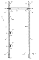
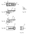
- FIG. 1 Scaffold 20 shown comprises two adjoining vertical scaffolding panels 23.1 and 23.2, each comprising four scaffolding layers or floors 20.1 to 22.4.
- the first framework field shown on the left is constructed from scaffolding positioning frame 21 according to the invention.
- Each scaffold positioning frame 21 consists of two supports 32.1 and 32.2 designed as vertical stems, which are connected to a transverse arm 35 permanently, here by welding, bending and torsion-resistant.
- the transverse arm 35 extends here perpendicular to the longitudinal axes 33 of the two supports 32.1 and 32.2 in the region of their respective upper ends 36.1 and 36.2, so that in the use position 34 downwardly open U- or H-shaped scaffolding frame 21; 21.1, 21.2 is formed.
- the embodiments shown are the scaffolding frame 21; 21.1, 21.2 each designed with a support 32.1 according to the invention, which is designed with a fastening device 38 according to the invention for attaching at least one inventive railing device 28, here in particular in the form of balusters 28.1, 28.2.
- a fastening device 38 for attaching at least one inventive railing device 28, here in particular in the form of balusters 28.1, 28.2.
- Each support 32.1 according to the invention here has two attachment devices 38 arranged in the position of use 34 of the support 32.1 at a vertical distance from each other for the connection of fall protection means in the form of Railing elements 28 on.
- each two substantially parallel railing rods 28.1, 28.2 attached to the fasteners 38 of the outer, respectively wall remote supports 32.1.
- the other or inner stems 32.2 of the frame rack 21 can be placed, for example, in the immediate vicinity of a wall, not shown, for example of a building, so that then on this side of the frame 20, as in FIG. 1 shown that fall protection means or off-road facilities 28 can be omitted.
- Each support 32; 32.1, 32.2; 32.4 of the lowermost scaffold layer or floor 22.1 is here attached to a so-called initial piece 27, which is usually designed with an upwardly pointing pipe socket.
- the inner diameter of this pipe socket is slightly larger than the outer diameter of the lower ends 37.1, 37.2 of the supports 32; 32.1, 32.2, 32.4, so that the supports 32; 32.1, 32.2, 32.4 can each be inserted into one of these pipe sockets of the starting pieces 27.
- the starting pieces 27 are usually provided with a spindle and a spindle nut screwed thereon, whereby a height or level adjustment of the supports 32; 32.1, 32.2; 32.4 can be achieved.
- Each start piece 27 here has a perforated disc 30, which is provided with openings.
- connection heads horizontal rod elements 24, 25, in particular longitudinal and cross bars bars, to the pipe socket. These connection points are also referred to as connection nodes 29, 29 '.
- rod elements usually longitudinal latch 24 and crossbar 25 are used.
- the longitudinal bars 24 and the cross bar 25 are in each case wedged in pairs to the pipe socket of the starting pieces 27 that two parallel longitudinal bars 24 and two perpendicular thereto, but with each other parallel cross bars 25, a stable rectangular base frame is constructed. Starting from this then built in a substantially horizontal plane base frame then the framework 20 is built up.
- the supports 32; 32.1, 32.2, 32.3, 32.4, 32.5 are usually designed as tubes.
- On or at the transverse arms 35; 35.1, 35.2 of the frame rack 21; 21.1, 21.2 can covering units, preferably in the form of scaffold floors 31, are attached, which are provided with running and / or work surfaces and which limit the respective floor or scaffold layer 22.1, 22.2, 22.3, 22.4 downwards and upwards horizontally.
- railing bars 28.1 and 28.2 provide a longitudinal fall protection protection, are here on the narrow lateral sides perpendicularly extending side railing 28.3 between the supports 32.1 and 32.2 of the scaffolding rack 21 according to the invention attached, as in FIG. 1 shown on the left outside.
- second framework field 23.2 is constructed with scaffolding elements of a modular framework of the so-called Layher Allround modular scaffold system.
- This comprises separate, designed as vertical stems support 32.4, which are provided in the longitudinal direction with a number of spaced in a same grid spacing perforated discs, here with four perforated discs.
- longitudinal latch 24 and Cross bar 25 and optionally not shown diagonal bar with the help of known wedge connecting heads 275 wedged.
- two of these stems 32.4 are connected in the region of their upper ends with a horizontal bar element 25, which is typically a round bar or an upwardly open U-profile bar.
- pad units in the form of scaffold floors 31 can be hung or suspended directly or preferably via hooks.
- the distance of the top hole 30 in the position of use of the respective handle 32.4 from the lower end thereof corresponds to the distance between the perforated disks 30 fixed to the supports 32.1 and 32.2 of the inventive scaffold setting frame 21 in the region of their upper ends 36.1, 36.2 from the lower ends 37.1, 37.2 thereof Supports 32.1, 32.2.
- a scaffold or a scaffold field 23.1 with the scaffold positioning frame 21 according to the invention; 21.1, 21.2 or with supports 32 according to the invention; 32.1, 32.2 is formed to connect seamlessly with a scaffold or a framework field 23.2 of a modular scaffolding, so that a step-free transition between the pad units or scaffolding floors 31 of the first frame field 23.1 with the pad units or scaffold floors 31 of the second frame field 23.2 is possible.
- the railing bars or railing bars 28.4 of the modular scaffolding forming the second scaffolding field 23.2 are directly in the region of the fastening devices 38 according to the invention of the supports 32 according to the invention; 32.1, 32.2 attached, for example by means of clampable perforated discs.
- the balusters 28.1, 28.2 of the first frame field 23.1 are arranged, for example, slightly above the balusters 28.4 of the second frame 23.2 of the modular frame, whereby this vertical distance is only so small that it neither the use nor the safety of a "combination frame" constructed in this way. impaired.
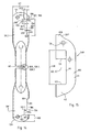
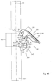
- FIG. 2 is a first embodiment of a scaffolding frame according to the invention 21.1 shown.
- This consists of two parallel and arranged in a plane supports 32.1, 32.2, which are formed and arranged in the position of use 34 as vertical stems.
- a perforated disc 30 which are designed in a known manner with breakthroughs for wedging provided with connecting heads with a wedge scaffolding elements.
- These perforated discs 30 here comprise the respective stem tube of the respective support 32.1, 32.2 in full circumference.
- the upper ends 36.1, 36.2 of the supports 32.1, 32.2 are each formed with a pipe connector 54.1, 54.2, whose outer diameter is slightly smaller than the inner diameter of the lower ends 37.1, 37.2 of the supports 32.1, 32.2. In this way, a plurality of such supports 32.1, 32.2 or positioning frame 21, as in FIG. 1 shown, put on each other.
- This cross arm 35.1 is formed here with a round tube, which is preferably connected at its two ends in one piece with wedge-shaped to the stem and pulley center tapered connecting heads 75.1 and 75.2. This connection heads or at least one of them is or are preferably produced by forming the round tube.
- This scaffold positioning frame 21.1 is formed with a vertical frame element 105.1, which is designed with the one support 32.1 and the thereto permanently, preferably by welding, fixed cross arm 35.1.
- European patent application no. 06021346.9 and German Utility Model Application No. 20 2006 015 586.4 be referenced, whose content is included in full at this point for the sake of simplicity, so that therefore the entire disclosure content of these two patent applications is also the subject of the invention described herein.
- FIG. 3 shows a second embodiment of a scaffolding frame according to the invention 21.2 shown. This differs from the one in FIG. 2 shown scaffolding frame 21.1 exclusively by the shape of the transverse arm and its detailed connection to the two supports 32.1 and 32.2, so that reference is made with respect to the remaining details to the above statements to the scaffolding frame 21.1 can be. Accordingly, in FIG. 3 the same elements with the same reference numerals as in FIG. 2 ,
- the cross arm 35.2 of in FIG. 3 shown scaffolding frame 21.2 is formed with an upwardly open U-profile tube or U-cross bar 35.2. This or this is connected at its two ends here in one piece with a pinch profile connection head 175.1, 175.2. These connection heads 175.1, 175.2 or at least one of them is or are preferably produced by forming the U-profile tube. Each of these connection heads 175.1 and 175.2 in turn has a horizontal Aufsteckschlitz, by means of which the respective connection head 175.1, 175.2 attached to the respective perforated disc 30 of the respective support 32.1, 32.2 and there again with both the perforated disc and with the stem to a bending and torsionally stiff, downwardly open U- or H-shaped frame rack 21.2 is welded.
- Each of the scaffolding frame 21 according to the invention; 21.1, 21.2 thus has at least one inventive support 32.1 made of metal, which is designed in particular as a vertical handle for a frame 20, in particular a facade scaffold, a podium, a staircase or the like space structure.
- the support 32.1 according to the invention has a fastening device 38 according to the invention for fastening at least one railing device 28, in particular a single or double railing, preferably a railing rod 28.1, 28.2 on the support 32.1.
- This fastening device 38 has a holder 40 for the railing device 28.
- the holder 40 is permanently connected here by welding to the support 32.1.
- the holder 40 has a transverse direction in a first direction 41, preferably perpendicular to the longitudinal axis 33 of the support 32.1 extending away from this support element 42 having a in use position 34 of the support 32.1 horizontal bearing surface 43 for vertical support of the railing device 28.
- the fastening device 38 also has a, preferably captive, connected to the support 32.1, here designed with one or as a locking lever 70, locking element 45 with a locking surface 46; 46.1, 46.2 for positive locking, preferably clamping force-free locking of the railing device 28 against vertical removal of the same in the use position 34 of the support 32.1 upwards in a locking position 47.
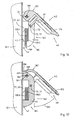
- the locking element 45 is pivotable about a pivot axis 50 from an opening or unlocking position 48 (FIG. FIGS. 4 and 5 ), preferably manually, into a locking position 47 (FIG. FIGS. 1 . 2 . 3 and 6 ), here in the use position 34 of the support 32.1 down, pivot.
- the locking surface 46 of the locking element 45 of the support surface 43 of the support member 42 is opposite.
- the locking surface 46 is arranged in the locking position 47 and in the use position 34 of the support 32.1 at a vertical distance 51 above the support surface 43 of the support element 42.
- the pivot axis 50 extends perpendicular to the longitudinal axis 33 of the support 32.1 and also perpendicular to the first direction 41, with which the support member 42 extends away from the support 32.1.
- the holder 40 has a completely closed passage opening 57 for insertion of an end 58.1, 58.2 of the at least one railing device 28, in particular of the railing rod 28.1, 28.2, which, at a transverse distance 59 to the support 32.1, here parallel to the longitudinal axis 33rd the support 32.1 in its position of use 34 upwardly extending, here integrally attached to the support member 42 support member 44 of the bracket 40 for laterally supporting the support member 56 of the railing device 28 is limited (see in particular FIGS. 4 to 6 ).
- the opening edge 61 of the passage opening 57 which here is formed with the U-shaped profile and designed as a bracket 65 holder 40 on the one hand and the outer surface of the support 32.1 on the other hand, clamped in the position of use 34 of the support 32 to a vertical opening plane, here the longitudinal axis 33 of the support 32.1 contains. Accordingly, the passage opening 57 in the position of use 34 of the support 32.1 here as a vertical, in the direction parallel to the longitudinal axis 33 of the support 32.1 extending receiving slot 63 designed.
- the holder 40 is designed with a bracket 65 made of flat material, which is a stamped part here, but which may also be designed in particular as a cast or forged part made of metal.
- This bracket 65 thus has the designed as a receiving slot 63 Through hole 57 for receiving the support member 56 of the railing device 28 on or limits this passage opening 57.
- the bracket 65 is arranged parallel to the longitudinal axis 33 of the support 32.1 and its legs are welded to the support 32.1.
- the locking element 45 is here designed with a manually operable locking lever 70 which is fixed here on the in use position 34 of the support 32.1 upper leg of the holder 40 by means of a here designed as a rivet 66 and the pivot axis 50 containing fastener.
- the locking lever 70 is preferably made of plastic.
- the locking lever 70 has a perpendicular to the pivot axis 50 extending longitudinal slot 71, in which in the locking position 47 of the locking lever 70, a majority of the vertical support member 44 of the holder 40 and the bracket 65 is added.
- the locking lever 70 consists of a pivoting and locking part 62 and an integrally connected thereto actuating part 60.
- the latter tapers concavely rounded towards its free end, in this way an advantageous attacking with a finger of a hand of an operator, for Purpose of a simple transfer of the locking lever 70 from its locking position 47 to reach up to its unlocking or in an open position 48.
- the articulation and locking part 62 of the locking lever 70 comprises an opening contained in the mounting position, the pivot axis 50, through which a part of the rivet 66 is inserted therethrough.
- the articulation and locking part 62nd further comprises a formed as an eccentric body 76 Andschreibharm 72 which engages upon pivoting of the locking lever 70 from the unlocked position 48 in the locking position 47 with a here formed as a cylindrical pin 77 counter body 73 engages or is engaged.
- the mating body 73 is fixed, preferably permanently, to the support member 44 so as to extend beyond both sides of the side surfaces of the bracket 65.
- the longitudinal axis 78 of the pin 77 is perpendicular to the longitudinal axis 33 of the support 32.1 and arranged parallel to the pivot axis 50.
- the longitudinal axis 78 of the pin 77 further extends perpendicular to the first direction 41, with which the support element 42 extends away from the support 32.1.
- the pressure body 72 of the locking lever 70 is designed as an eccentric to the pivot axis 50 arranged eccentric 76.
- the locking lever 70 in the region of its transition between the actuating part 60 and the articulation and locking part 62 has an outwardly adjoining the eccentric body 76 locking recess 79, in which the attached to the support member 44 of the holder 40 Pin 77 engages latching in the locking position 47.
- the invention also relates to a connection arrangement for a railing device 28, the at least one support 32.1 for a framework 20, in particular a facade scaffold, a podium, a staircase or the like space structure and one in particular designed as a single or double railing, preferably with one or as a railing rod 28.1, 28.2 designed railing device 28 includes, which is fastened by means of the fastening device 38 to the support 32.1.
- the locking surface 46 of the locking element 45 is in the locking position 47 of the support surface 43 of the support member 42 and the locking surface 46 is in the locking position 47 and in the use position 34 of the support 32.1 at a vertical distance 51 above the support surface 43 of the support member 42nd arranged, which is greater than the height 67 of resting on the support surface 43 of the support member 42 of the holder 40 support member 56 of the railing device 28.
- the invention also includes a connection arrangement 80 for a railing device 28, the at least one inventive support 32.1, in particular a vertical handle, made of metal, for a frame 20, in particular a facade scaffold, a podium, a staircase or the like space frame and at least one, especially as Single or double railing designed, preferably with or as a railing rod 28.1, 28.2 designed railing device 28 which is fastened by means of a fastening device 38 to the support 32.1, wherein the support 32.1 comprises a holder 40 for the railing device 28, wherein the holder 40th , Preferably captive, in particular permanently, for example by welding, is connected or attached to the support 32 and wherein the holder 40 in a first direction 41 transversely, preferably perpendicular to the longitudinal axis 33 of the support 32 away from the latter extending support member 42 with an i n use position 34 of the support 32.1 horizontal supporting surface 43 for vertical support of the railing device 28, on which a, preferably in the region of an end 58.1, 58.2
- the fastening device 38 and the railing device 28 are designed coordinated so that the railing device 28, although the locking element 45 is in the locking position 47, in the use position 34 of the support 32 from below, in particular obliquely from below, on the support surface 43 of Support member 42 of the holder 40 can be placed or can be hung there, and starting from this position can be pivoted upwards and into a mounting position 49, in which the railing device 28 is secured against removal from the holder 40 in any direction.
- the holder 40 has a fully closed passage opening 57 in the form of a receiving slot 63 for insertion of an end 58.1, 58.2 of the at least one railing device 28 and the railing rod 28.1, 28.2, through which the end 58.1, 58.2 of the railing device 28 and des Railing rod 28.1, 28.2 is inserted through (see. Figures 5 and 6 ).
- the passage opening 57 is, in the position of use 34 of the support 32, designed as a vertical parallel to the longitudinal axis 33 of the support 32 extending receiving slot 63, in which the support member 56 of the railing device 28, here the end 58.1, 58.2 a balancing rod 28.1, 28.2 or both railing rods 28.1, 28.2, inserted or pushed through ( Figures 5 and 6 ).
- the receiving slot 63 has a height 68 which is greater than the width or the height 67 of at least one end 58.1, 58.2 of the ends 58.1, 58.2 of the railing device 28 or of the railing rod 28.1, 28.2. Further, the passage opening 57 has a width 59 which is greater than the thickness or width 82 of the support member 56 of the railing device 28 and the railing rod 28.1, 28.2.
- the passage opening 57 has a width 59 which is slightly larger than twice the thickness or width 82 of the support member 56 of the railing device 28 or of the railing rod 28.1, 28.2, so that in the holder 40 so up to two such railing devices 28, 28 or railing rods 28.1, 28.2 can be suspended and locked by means of the locking lever 40.
- the railing device 28 has in the region of at least one end 58.1, 58.2, in this case in the region of its two flattened ends 58.1, 58.2, in each case one extending parallel to the longitudinal axis 83 of the end 58.1, 58.2 or the railing rod 28.1, 28.2, with the support part 56th for resting on the bearing surface 43 of the support element 42 of the holder 40 inwardly limited, and outwardly, respectively transversely or perpendicular to the longitudinal axis 83 of the railing device 28 open first recess 86.
- first wall portion 87 extending transversely, here approximately perpendicular to the longitudinal axis 83 of the end 58.1, 58.2 or the railing device 28, in this case the railing rod 28.1, 28.2, which here is delimited in the form of a hook-shaped nose 88.
- the first recess 86 is bounded in the direction of the longitudinal axis 83 by two spaced-apart wall parts 87 and 89.
- the wall portion 89 is concavely rounded (at 91) and the nose 88 limiting wall portion 87 is provided with an insertion 92nd designed.
- a second recess 94 adjoins the first wall part 87 or the nose 88. This is limited by a parallel here to the longitudinal axis 83 of the railing device 28 and the railing rod 28.1, 28.2 extending and recessed relative to the first recess 86 bearing surface 95 of the support member 56 and two, here parallel, a support surface spacing 98 to each other having support surfaces 97.1, 97.2 limited.
- These support surfaces 97.1, 97.2 here extend perpendicular to the longitudinal axis 83 of the end 58.1, 58.2 or the railing device 28 or the railing rod 28.1, 28.2.
- the support surface spacing 98 of these support surfaces 97.1, 97.2 is greater than the width 99 of the support element 42 of the support 40 in the region of the support surface 43 of the support element 42, so that the railing device 28, respectively the respective railing rod 28.1, 28.2, there with its second recess 94 positively can engage.
- the support surface distance 98 is preferably about 1.5 to 3 times the width 99 of the support element 42 in the region of the support surface 43, so that manufacturing and in particular installation tolerances can be compensated so that it is always ensured that the railing device 28 and the Railing rod 28.1, 28.2, in each case reliably and safely in the region of its or its two ends 58.1, 58.2 in each case a holder 40 of a support 32.1 according to the invention can be mounted in installation or use position 49.
- the length 93 of the first recess 86 extending in the direction of the longitudinal axis 83 of the end 58.1, 58.2 or of the railing rod 28.1, 28.2 is much larger than the first measured in the same direction distance 100 between the free end 101 of the respective end 58.1, 58.2 of the railing device 28 and the baluster 28.1, 28.2 associated support surface 97.2 of the second recess 94 and this free end 101 of the railing device 28 and the railing rod 28.1, 28.2.
- connection arrangement is also that the distance 51 between the support surface 43 of the support element 42 and the locking surface 46 of the locking element 45 in the locking position 47 is greater than the largest distance between the of the free end 101 of the railing device 28 and the railing bar 28.1, 28.2 pointing away and the first recess 86 delimiting surface 90 of the first wall portion 87 and the nose 88 and this free end 101 of the railing device 28 and the railing rod 28.1, 28.2, in particular greater than the largest distance 102 between the from the free end 101 of the railing device 28 and the railing rod 28.1, 28.2 pointing away and the second recess 94 limiting support surface 97.2 and this free end 101 of the railing device 28 and the railing rod 28.1, 28.2.
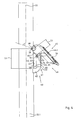
- a second embodiment of a support or fastening device according to the invention for fixing railing devices is with his or her parts in the FIGS. 11 to 18 illustrated.
- the same parts are denoted by the same reference numerals with respect to the previously discussed embodiments.
- the holder 140 and the bracket 165, the locking element 145 and the locking lever 170, the fixing means containing the pivot axis 50 66 and also the railing device 128; 128.1, 128.2 slightly differently designed than the previously described parts 40 and 65, 45 and 70, 166 and 28; 28.1, 28.2.
- the fastening means and / or the railing device can also be designed the same, as in the embodiments described above.
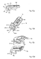
- FIGS. 12a to 12d and 13a to 13f The exact design of the locking lever 170 acting as a locking element 170 according to the second embodiment is particularly in the FIGS. 12a to 12d and 13a to 13f shown.
- This embodiment differs from that in particular in the FIGS. 7a to 7d and 8a to 8f shown in the first embodiment in that in the open position 48 the handle 32.1 facing region of the articulation and locking member 162 between the pivot axis 50 and the locking surface 46; 46.1, 46.2 a here approximately rectangular limited recess 210 is provided.
- the inner contour of this recess 210 corresponds to the inner contour of the passage opening 57 of the holder 140 in the region of its upper end. This leads into the in FIG.
- the shape or contour of the Andschreib stresses 172 is slightly changed in the locking lever 170 compared to the locking lever 70.
- the Andschreib stresses 177 is now designed such that it, as in FIG. 16 shown in the said or desired open position 48 abuts against the designed as a pin counter body 73. In this way, a gravity-induced (further) pivoting of the locking lever 170 is prevented in this open position 48 down.
- the Andschreibêt stresses 172 is no longer designed here as an eccentric body.
- the Andschreibharmharmharm 172 is designed in this embodiment with a convexly outwardly curving Andschreibwand which is separated from a slot 85 of the remaining rear part of the articulation and locking member 162.
- the Andschreib stresses 172 in the course of a deliberate manual pivoting of the locking lever 170 of the in the Figures 11 . 16 and 17 shown opening or unlocking position in the in FIG. 18 shown locking or locking position 47 are pressed back resiliently under exercise of a certain pivoting force so that it can pass through the acting as a counter-body 73 pin 77.
- this second embodiment further measures are provided in this second embodiment, by which it is ensured that the Locking lever 170, viewed from its closed or locking position 47, only by a certain maximum opening angle 265 about its pivot axis 50 can be pivoted upwards.
- this maximum opening angle 265 is less than about 60 degrees, in particular less than or equal to about 45 degrees (see in particular FIG. 17 ).
- this maximum opening angle 265 is less than about 60 degrees, in particular less than or equal to about 45 degrees (see in particular FIG. 17 ).
- the locking lever 170 has a stopper body 209 which extends horizontally between the separated by the longitudinal slot 71 bearing bodies 208.1 and 208.2. Furthermore, it is provided that the holder 140 has at its upper end a nose 206 which forms a stop 207 for the stop body 209 of the locking lever 170 or its outer surface facing away from the handle 32.1 ( FIG. 17 ).
- the stop 207 of the holder 140 and the stop member 209 of the locking lever 170 are designed coordinated so that the locking lever 170, as mentioned above, only about a certain maximum opening angle 265 about its pivot axis 50 can be pivoted upward, here about 45 degrees is.
- the locking lever 170 is no longer fastened and supported on the holder 140 with the aid of a rivet acting as a fastening means but now with the aid of a pin 166 which likewise functions as a fastening means, here preferably over its entire length, in particular slotted, preferably hollow or sleeve-shaped, clamping pin 166 is designed. This one is especially good in FIG. 18 to see.
- the clamping pin 166 is clamped non-positively on a receiving bore of the holder 140. On the clamping pin 166 thus clamped, the locking lever 170 is rotatably mounted about its pivot axis 50.
- the two bearing bodies 208.1 and 208.2 of the locking lever 170 each have a bearing bore or bore 211.1 and 211.2, whose inner diameter is slightly larger than the outer diameter of the clamping pin 166 in these areas.
- a clamping pin instead of a clamping pin, other pins or bolts may be provided, for example, a grooved pin. This can be provided centrally with a thickening, which is then clamped there when pressed into the bore of the holder 140 under press fit or will.
- Such construction are easier to manufacture compared to a fastening with a rivet and, if necessary, even released again and are also cheaper in the rest.
- a second embodiment of a railing device 128; 128.1, 128.2 is in particular in FIG. 14 illustrated.
- the handrail bar 128 shown there; 128.1, 128.2 is different from the one in FIG. 9 shown railing rod 28; 28.1, 28.2 substantially by a deeper and wider second recess 194. This therefore has a greater width or a larger support surface distance 198 and a greater depth 103.
- the in FIG. 9 shown railing rod 28; 28.1, 28.2 was the greater depth 103 of the second recess 194 of the baluster 128; 128.1, 128.2 achieved by the fact that the depth 204 of the Support surface 196 was reduced accordingly.
- the larger width or the larger support surface distance 198 was based on the in FIG.
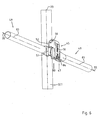
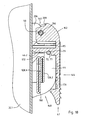
- FIG. 19 a further support according to the invention is shown, which comprises a pivotable locking lever 170 according to the second embodiment according to the invention fastening device according to a third Embodiment designed with a holder 240 according to a third embodiment.
- the holder 240 is according to FIG. 19 slotted (horizontal slot or gap 264), but still has a substantially fully enclosed or closed through opening 57 (receiving slot 63) for insertion of one end (58.1, 58.2) of the at least one railing device (28 or 128).
- the holder 240 is designed with its slot 264 so matched to the cross-country device that the inserted or in the through opening 57 or hinged railing device 28, 128 and then not through the slot 264 unhooked or pulled out of the holder 240 or can be removed when the locking element or the locking lever is in one or its opening or unlocking position.
- the slit 264 separates the non-slotted or uninterrupted shackle in the first and second embodiments into two parts, namely a lower element comprising the support element 42 and a lower support element 244.1 and an upper element comprising an upper support element 244.2 and a fastening body 192.
- the opposite ends of the support elements 244.1 and 244.2 have a width of the slot or gap 264 corresponding distance 243 from each other.
- the holder 240 is provided with a lower support member 244.1 containing lower receiving profile 242 for receiving and supporting the railing device 28; 128 designed.
- the receiving profile 242 is at its end delimiting the slot or slot 243 of the support element 244.1 technological end of the stem 32.1 permanently, preferably by welding, attached.
- the fastening body 192 which is connected in one piece to the other or upper support element 244.2, is also fixed permanently to the handle 32.1, preferably by welding, at its end pointing away from the end of the support element 244.2 delimiting the slot or gap 243.
- the locking lever 170 in contrast to the aforementioned embodiments of a holder 40, 140, now not on the receiving element 24 containing part of the holder 240 and not on a support element of the support elements 244.1, 244.2 of the holder 240, but at one or .,
- the invention also relates to a scaffolding frame, in particular a scaffolding frame 21; 21.1, 21.2, with at least one support 32.1 according to the invention and with at least one transverse arm 35; 35.1, 35.2, which is attached at least to the at least one support 32.1, preferably captive, in particular permanently, for example by welding.
- the invention further relates to a scaffolding frame, in particular a scaffolding frame 21; 21.1, 21.2, with at least one connecting arrangement 80 according to the invention, wherein at least one support 32.1 has at least one transverse arm 35; 35.1, 35.2, preferably captive, in particular permanently, for example by welding, is attached.
- the invention also relates to a scaffold 20, in particular a scaffolding, with at least four vertical supports 32; 32.1, 32.2; 32.4, 32.5, to which preferably at least one covering unit, in particular a scaffolding floor 31, horizontal bar elements 24, 25 and / or at least one diagonal element 26 for stiffening the framework 20, are mounted, and with at least one support 32.1, 32.3 according to the invention and / or with at least one connection arrangement 80 according to the invention and / or with at least one vertical frame element 105.1, 105.2 according to the invention and / or with at least one scaffolding frame according to the invention.
- the railing device 28 in particular the railing bars 28.1, 28.2, both from the same scaffolding level or floor 22.1 to 22.4 and also, if necessary, to provide a leading railing of one or the lower lying scaffold position or floor can be installed from or can.
- a method according to the invention for installing a railing device 28 from the same stand position can be defined as follows:
- a railing device 28, 128 on the brackets 40, 140, 240 of two adjacent columns 32.1, 32.3 can then be made such that the railing device 28, 128 and the railing rod 28.1, 28.2; 128.1, 128.2 first in the region of a support surface 96, 196 of the first recess 86, 186 of a first end 58.1 of its or its ends 58.1, 58.2 on the support surface 43 of the support element 42 of the holder 40, 140, 240 of a first support 32.1, 32.3, preferably in its position of use 34 horizontally, is placed, wherein the locking element 45, 145 of the fastening device 38 of the first support 32 is in its unlocked position 48, and that then the railing device 28, 128 and the railing rod 28.1, 28.2; 128.1, 128.2 so long in the direction of the holder 40, 140, 240 of the adjacent second support 32.1, 32.3, is moved until the respective support surface 95, 195 of the respective second recess 94
- the railing device 28, 128 is thus installed by being inserted on one side into the recess or first recess 86, 186 beyond the point of insertion defined by the second recess 94, 194, then threaded on the other side and finally retracted is until the railing device 28, 128 then at its two Einitatiyaken, respectively at its two second recesses 94, 194 on the support elements 42 of the Mounts 40, 140, 240 locked or snapped so that then the bearing surfaces 95, 195 of the two second recesses 94, 194 of the railing device 28, 128 on the bearing surfaces 43 of the support members 42 of the brackets 40, 140, 240 of the two adjacent columns 32.1 , 32.3; 32.1, 32.3.
- the invention also relates to a method for attaching at least one railing device 28, 128 by means of a fastening device 38 to a support 32 for a scaffold 20, a podium, a staircase or the like space frame, wherein the fastening device 38 is a holder 40, 140, 240 for the railing device 28, 128 comprises, and wherein the holder 40, 140, 240, preferably captive, in particular permanently, for example by welding, with the support 32, in particular with a support 32.1 according to the invention, preferably with a vertical stem, made of metal, is connected and the one in a first direction 41 transversely, preferably perpendicular, to the longitudinal axis 33 of the support 32 extending away therefrom support member 42 having a support surface 43 for vertical support of, in particular as a single or double railing, preferably with or as a railing rod 28.1,
- the invention also relates to a method for fastening at least one railing device 28, 128 by means of a fastening device 38 to a support 32 for a scaffold 20, a podium, a staircase or the like space frame, wherein the fastening device 38 is a holder 40, 140, 240 for the Railing device 28, 128 includes, and wherein the holder 40, 140, 240 preferably captive, in particular permanently, for example by welding, with the support 32, preferably with a support 32.1 according to the invention, in particular with a vertical stem, made of metal, and the a support element 42 which extends transversely, preferably perpendicularly, in a first direction 41 to the longitudinal axis 33 of the support 32 and has a support surface 43 for vertical support, in particular as a single or double railing, preferably with one or as a railing rod 28.1, 28.2; 128.1, 128.2, preferably a part of a connection arrangement, in particular a part of a connection arrangement 80 according to the invention, wherein
- the locking lever 70, 170 are normally open.
- the railing devices 28, 128 can then by lifting up and then by a lateral displacement relative to the brackets 40, 140, 240 of the adjacent columns 32.1, 32.3; 32.1, 32.3. But it is also possible, as in the structure described above as a leading railing, proceed only in the reverse order.
- supports 32.3 which are plugged here on the supports 32.1 of the scaffold rack 21.
- These supports 32.3 can, as in FIG. 1 shown to have a shorter, in particular about half as long, length as the supports 32.1. It is understood, however, that the supports of the uppermost scaffold layer or floor 22.4 may also have another, in particular a greater length, preferably a length corresponding to the length of the supports 32.1. It is further understood that for the construction of a scaffold also only or additionally separate inventive supports 32.1, 32.3 and / or from or with at least an inventive support 32.1, 32. 3 and at least one transverse arm 35 formed vertical frame members 105 can be used.
Landscapes
- Architecture (AREA)
- Engineering & Computer Science (AREA)
- Mechanical Engineering (AREA)
- Civil Engineering (AREA)
- Structural Engineering (AREA)
- Bridges Or Land Bridges (AREA)
- Refuge Islands, Traffic Blockers, Or Guard Fence (AREA)
- Mutual Connection Of Rods And Tubes (AREA)
- Steps, Ramps, And Handrails (AREA)
- Clamps And Clips (AREA)
- Ladders (AREA)
- Joining Of Building Structures In Genera (AREA)
- Orthopedics, Nursing, And Contraception (AREA)
- Building Environments (AREA)
- Catching Or Destruction (AREA)
Priority Applications (1)
| Application Number | Priority Date | Filing Date | Title |
|---|---|---|---|
| PL08005771T PL1983129T3 (pl) | 2007-04-18 | 2008-03-27 | Podpora dla przestrzennej konstrukcji nośnej oraz układ połączeniowy dla urządzenia poręczowego i sposób zamocowania urządzenia poręczowego na podporze |
Applications Claiming Priority (1)
| Application Number | Priority Date | Filing Date | Title |
|---|---|---|---|
| DE102007018314A DE102007018314A1 (de) | 2007-04-18 | 2007-04-18 | Stütze für ein Raumtragwerk sowie Verbindungsanordnung für eine Geländereinrichtung und Verfahren zum Befestigen einer Geländereinrichtung an einer Stütze |
Publications (3)
| Publication Number | Publication Date |
|---|---|
| EP1983129A2 EP1983129A2 (de) | 2008-10-22 |
| EP1983129A3 EP1983129A3 (de) | 2009-04-15 |
| EP1983129B1 true EP1983129B1 (de) | 2011-06-29 |
Family
ID=39620229
Family Applications (1)
| Application Number | Title | Priority Date | Filing Date |
|---|---|---|---|
| EP08005771A Active EP1983129B1 (de) | 2007-04-18 | 2008-03-27 | Stütze für ein Raumtragwerk sowie Verbindungsanordnung für eine Geländereinrichtung und Verfahren zum Befestigen einer Geländereinrichtung an einer Stütze |
Country Status (13)
| Country | Link |
|---|---|
| US (1) | US8931594B2 (pl) |
| EP (1) | EP1983129B1 (pl) |
| CN (2) | CN101680233B (pl) |
| AT (1) | ATE514825T1 (pl) |
| AU (1) | AU2008241165B2 (pl) |
| BR (1) | BRPI0810232B1 (pl) |
| DE (1) | DE102007018314A1 (pl) |
| ES (1) | ES2367823T3 (pl) |
| NZ (1) | NZ579781A (pl) |
| PL (1) | PL1983129T3 (pl) |
| RU (1) | RU2453668C2 (pl) |
| WO (1) | WO2008128500A2 (pl) |
| ZA (1) | ZA200906068B (pl) |
Families Citing this family (38)
| Publication number | Priority date | Publication date | Assignee | Title |
|---|---|---|---|---|
| EP2189592B1 (en) * | 2008-11-21 | 2014-12-24 | Haki AB | Locking device for modular scaffolding or similar |
| US9580147B2 (en) | 2011-09-16 | 2017-02-28 | Malibu Boats, Llc | Surf wake system for a watercraft |
| CN102677883B (zh) * | 2012-05-28 | 2014-07-30 | 开平市优赢金属制品有限公司 | 拓展工作台面的脚手架 |
| US8789335B2 (en) * | 2012-07-25 | 2014-07-29 | Tait Towers Manufacturing, LLC. | Portable structure |
| CN104662239A (zh) * | 2012-08-02 | 2015-05-27 | 福姆700私人有限公司 | 模板支撑元件 |
| US20140223745A1 (en) * | 2013-02-08 | 2014-08-14 | Davis Eberhart | Bolted Structural Connection Systems |
| US10570630B2 (en) * | 2013-05-14 | 2020-02-25 | Nicholas Mark SHAW | Suspended scaffolding structure and connector therefor |
| US9637931B2 (en) * | 2013-10-30 | 2017-05-02 | University Health Network | Connector apparatus |
| US9522421B2 (en) * | 2014-02-13 | 2016-12-20 | Norgren Automation Solutions, Llc | Bar mounted tool adaptor |
| US9556624B1 (en) * | 2014-06-27 | 2017-01-31 | Utility Service Co., Inc. | Scaffold system |
| CN104440109B (zh) * | 2014-11-25 | 2017-04-26 | 佛山市南海区西樵西岸高竹铝梯厂 | 一种铝梯生产装置 |
| CA2983294C (en) * | 2015-04-24 | 2022-07-19 | Deltak Manufacturing, Inc. | A lockable scaffold toeboard system |
| US10837230B1 (en) * | 2016-07-29 | 2020-11-17 | Johnny Curtis | Ladder hoop |
| CN106088563A (zh) * | 2016-08-30 | 2016-11-09 | 苏州银海机电科技有限公司 | 一种搭梯架 |
| US10407984B2 (en) * | 2016-11-16 | 2019-09-10 | The Boeing Company | Adjustable platform system |
| CA3066963A1 (en) * | 2017-05-09 | 2018-11-15 | At-Pac China Business Trust | Modified ledger and modular scaffold system with continuous work surface |
| JP6889630B2 (ja) * | 2017-08-01 | 2021-06-18 | 日鉄建材株式会社 | 階段開口部手摺および階段開口部手摺を組み込んでなる仮設足場 |
| CN108035617A (zh) * | 2017-12-26 | 2018-05-15 | 国网湖北省电力公司咸宁供电公司 | 一种施工围栏框架及施工围栏 |
| DE102018103897A1 (de) * | 2018-02-21 | 2019-08-22 | Wilhelm Layher Verwaltungs-Gmbh | Gerüst mit einer Aushebesicherungsvorrichtung und Verfahren zur Sicherung eines Gerüstbodens gegen Ausheben |
| DE102018203653A1 (de) * | 2018-03-12 | 2019-09-12 | Peri Gmbh | Gerüst mit Gerüstriegel und Gerüstelementen sowie ein Verfahren zum Aufbau eines Gerüsts |
| DE102018114244A1 (de) * | 2018-06-14 | 2019-12-19 | Wilhelm Layher Verwaltungs-Gmbh | Einzelner Gerüststiel |
| CN108868113B (zh) * | 2018-08-28 | 2024-06-28 | 广州云奇科技有限公司 | 盘扣式脚手架组合连接固定装置 |
| US10844888B2 (en) * | 2018-10-12 | 2020-11-24 | Titan Formwork Systems, Llc | Clamp for connecting ledger to shoring post |
| US11370508B1 (en) | 2019-04-05 | 2022-06-28 | Malibu Boats, Llc | Control system for water sports boat with foil displacement system |
| AU2020203296B2 (en) * | 2019-05-22 | 2025-11-27 | Voideck Ipco Limited | Improvements relating to void platforms |
| CN110630168B (zh) * | 2019-09-06 | 2024-07-02 | 苏州飞华铝制工业有限公司 | 一种具备锁定功能的可折叠支柱结构 |
| CH716838A1 (de) * | 2019-11-25 | 2021-05-31 | Vitra Patente Ag | Traverse, Traversensatz und Möbelbausatz. |
| CH716837A1 (de) * | 2019-11-25 | 2021-05-31 | Vitra Patente Ag | Windverband und Möbelbausatz. |
| DE102019133939A1 (de) | 2019-12-11 | 2021-06-17 | Wilhelm Layher Verwaltungs-Gmbh | Vorrichtung zum lösbaren befestigen wenigstens einer geländereinrichtung an einem gerüstelement |
| US11932356B1 (en) | 2020-08-24 | 2024-03-19 | Malibu Boats, Llc | Powered swim platform |
| DE102021101768A1 (de) | 2021-01-27 | 2022-07-28 | Wilhelm Layher Verwaltungs-Gmbh | Anordnung von gerüstbauteilen |
| US12172732B1 (en) | 2021-06-17 | 2024-12-24 | Brunswick Corporation | Swim platform assemblies for boats |
| DE102021133941A1 (de) | 2021-12-20 | 2023-06-22 | Wilhelm Layher Verwaltungs-Gmbh | Anordnung von gerüstbauteilen und verfahren zur montage einer derartigen anordnung |
| US20230203825A1 (en) * | 2021-12-29 | 2023-06-29 | Emsee Engineering Inc. | Method and system for forming scaffolding |
| CN114575672B (zh) * | 2022-05-06 | 2022-07-19 | 山东金宇信息科技集团有限公司 | 一种可变形的公路施工用围挡装置 |
| DE102022113064A1 (de) | 2022-05-24 | 2023-11-30 | Wilhelm Layher Verwaltungs-Gmbh | Geländerelement, baugerüst mit einem derartigen geländerelement und verfahren zur demontage eines derartigen geländerelements |
| US20240328176A1 (en) * | 2023-03-29 | 2024-10-03 | ScaffoldMart | Breakdown Safety Rail System for Scaffold |
| CN118728050A (zh) * | 2024-07-04 | 2024-10-01 | 中交一公局集团有限公司 | 支架组件及支架组件安装方法 |
Family Cites Families (79)
| Publication number | Priority date | Publication date | Assignee | Title |
|---|---|---|---|---|
| US427180A (en) * | 1890-05-06 | George s | ||
| DE90210C (pl) | ||||
| US2849258A (en) * | 1958-08-26 | Clamping connections for framework | ||
| US1351053A (en) * | 1919-10-15 | 1920-08-31 | John J Macklem | Sectional scaffold |
| US1359452A (en) * | 1920-02-19 | 1920-11-16 | Howard I Walker | Scaffold |
| US1890029A (en) * | 1930-11-05 | 1932-12-06 | Delfs John | Scaffold |
| US2665950A (en) * | 1947-09-15 | 1954-01-12 | Wallace J S Johnson | Portable scaffold unit |
| US2674476A (en) * | 1948-10-06 | 1954-04-06 | Automatic Devices Inc | Connecting device |
| US2561938A (en) * | 1949-06-28 | 1951-07-24 | Patent Scaffolding Co Inc | Attachment for holding cross braces to end frame scaffolding |
| US2708606A (en) * | 1950-03-25 | 1955-05-17 | Miller Stamping Company | Scaffolding structure |
| US2726902A (en) * | 1953-08-10 | 1955-12-13 | Patent Scaffolding Co Inc | Automatic locks for sectional scaffolding |
| US2845307A (en) * | 1954-04-19 | 1958-07-29 | Superior Scaffold Company | Detachable coupling for scaffold elements |
| US2814535A (en) * | 1955-11-08 | 1957-11-26 | Zigmund J Jagiel | Brace rod securing means for scaffold frames or the like |
| US2813759A (en) * | 1956-08-01 | 1957-11-19 | Braun Anton | Brace locking device |
| US2891820A (en) * | 1956-11-23 | 1959-06-23 | Automatic Devices Inc | Scaffold structure |
| US2941616A (en) * | 1957-02-15 | 1960-06-21 | Werner Co Inc R D | Stairway type scaffold |
| US2971786A (en) * | 1958-04-25 | 1961-02-14 | Tubular Structures Corp Of Ame | Brace bar securing means for prefabricated tubular structures |
| US3017208A (en) * | 1959-05-29 | 1962-01-16 | Bil Jax Inc | Brace lock for modular scaffolding |
| US3122385A (en) * | 1960-09-13 | 1964-02-25 | Ponteggi Tubolari Dalminc Inno | Scaffolding-brace lock |
| US3221837A (en) * | 1963-10-07 | 1965-12-07 | Up Right Inc | Scaffold with folding stairway |
| US3174779A (en) * | 1964-02-17 | 1965-03-23 | Waco Porter Corp | Connecting structure |
| US3302751A (en) * | 1965-01-25 | 1967-02-07 | Russell W Ahlberg | Scaffolding construction |
| US3360287A (en) * | 1965-06-03 | 1967-12-26 | Bil Jax Inc | Scaffolding |
| CH439679A (de) | 1966-08-27 | 1967-07-15 | Huwyler Rudolf | Baugerüst |
| US3454131A (en) * | 1968-01-26 | 1969-07-08 | Up Right Inc | Scaffold |
| US3551011A (en) * | 1969-04-28 | 1970-12-29 | David W Alley | Quick releasing cross-brace latch for knock-down scaffolding |
| US3565212A (en) * | 1969-11-14 | 1971-02-23 | Up Right Inc | Combination beam support and latch means for walk-through platform |
| DD90210A1 (de) * | 1971-06-29 | 1972-05-20 | Geländer zur Montage bzw. Demontage für den Gerüstbau | |
| US3807884A (en) * | 1971-11-08 | 1974-04-30 | Symons Corp | Releasable metal scaffolding connector |
| GB1396602A (en) * | 1972-05-12 | 1975-06-04 | Thomas Ltd Martin | Builders staging |
| US3752262A (en) * | 1972-06-01 | 1973-08-14 | B Helms | Scaffold guard rail assembly |
| US3751081A (en) * | 1972-06-23 | 1973-08-07 | Symons Corp | Three-piece clamp assembly for the braces of scaffolding |
| US3867043A (en) * | 1973-11-29 | 1975-02-18 | Symons Corp | Brace lock assembly for scaffolding |
| AU518442B2 (en) * | 1977-06-06 | 1981-10-01 | Cyclone Scaffolding Pty. Limited | Scaffold interconnections |
| DE2757189C2 (de) | 1977-12-22 | 1983-07-28 | Eberhard 7129 Güglingen Layher | Gerüst mit Rohrständern und Doppelgeländern |
| JPS6146123Y2 (pl) * | 1978-12-12 | 1986-12-25 | ||
| DE3103339C2 (de) * | 1981-01-31 | 1982-12-09 | Gerhard 5090 Leverkusen Dobersch | Seitenschutzvorrichtung für Gerüste, insbesondere Stahlrohrgerüste |
| DE3108020A1 (de) | 1981-03-03 | 1982-09-30 | Eberhard 7129 Güglingen Layher | "schutzvorrichtung fuer metallgerueste" |
| DE3139980A1 (de) | 1981-10-08 | 1983-04-28 | Hünnebeck GmbH, 4030 Ratingen | Geruestrahmen |
| FR2516141B1 (fr) | 1981-11-10 | 1987-11-27 | Philippe Robert | Procede de montage d'un echafaudage et dispositif monte audit procede |
| US4493394A (en) * | 1982-05-24 | 1985-01-15 | Figgie International Inc. | Brace lock for scaffolding |
| DE8711664U1 (de) | 1987-08-28 | 1987-12-03 | Grund, Gerhard, 4132 Kamp-Lintfort | Gerüst, insbesondere Baugerüst |
| NL8700981A (nl) * | 1987-04-24 | 1988-11-16 | Alprokon Promotie Ontwikk Bv | Drager voor de leuning van een demontabel leuningsamenstel. |
| GB2214554B (en) * | 1988-01-15 | 1991-08-07 | Richard Maurice Morgan | Scaffold fitting |
| US4830144A (en) * | 1988-01-25 | 1989-05-16 | Saf-T-Green Manufacturing Corporation | Scaffold |
| DE3832480A1 (de) | 1988-09-24 | 1990-03-29 | Geb Layher Langer | Halterung fuer gelaender an geruesten |
| DE3934857A1 (de) * | 1989-10-19 | 1991-04-25 | Langer Ruth Geb Layher | Anschlusskopf fuer geruest |
| US5145030A (en) * | 1991-09-11 | 1992-09-08 | Waco International Corporation | Guard rail post |
| FR2682708A1 (fr) | 1991-10-16 | 1993-04-23 | Nagel Gilbert | Dispositif de verrouillage de barres pour l'assemblage et le blocage de garde-corps. |
| US5263550A (en) * | 1992-06-15 | 1993-11-23 | Wenger Corporation | Railing for portable staging |
| JPH0796833B2 (ja) * | 1992-09-25 | 1995-10-18 | 政太郎 佐藤 | 管材連結用クランプ金具組立体 |
| DE4406732C2 (de) * | 1993-07-07 | 1998-04-30 | Baumann Verwertungs Gmbh | Gerüst, insbesondere für das Bauwesen |
| DE19504038C2 (de) | 1995-02-08 | 2000-05-11 | Layher W Vermogensverw Gmbh | Gerüst |
| US6039150A (en) * | 1995-05-03 | 2000-03-21 | Palmer; Theodore R. | Building guard rail scaffold assembly |
| DE19602737A1 (de) * | 1996-01-26 | 1997-07-31 | Peri Gmbh | Gerüstknoten |
| DE19625545A1 (de) * | 1996-06-26 | 1998-01-02 | Plettac Ag | Verbindungsvorrichtung eines Auflageriegels |
| DE19655284B4 (de) | 1996-08-16 | 2008-01-24 | Peri Gmbh | Zerlegbares Fassadengerüst |
| DE19703558B4 (de) | 1997-01-31 | 2005-10-27 | Wilhelm Layher Vermögensverwaltungs-Gmbh | Stabeinrichtung für ein Gerüstsystem |
| JP2892349B1 (ja) * | 1998-06-05 | 1999-05-17 | 川崎重工業株式会社 | 手摺り取付装置 |
| DE19827284A1 (de) | 1998-06-19 | 1999-12-23 | Layher W Vermogensverw Gmbh | Stellrahmen für ein Gerüst |
| US6062341A (en) * | 1998-09-11 | 2000-05-16 | Safway Steel Products Inc. | Guard rail stud adapter |
| RU2160813C2 (ru) * | 1998-10-26 | 2000-12-20 | Акционерное общество "Нефтехимремстрой" | Строительные леса |
| DE19919358C1 (de) | 1999-04-28 | 2000-07-06 | Danila Peralta | Gerüst mit Haltevorrichtung für ein Geländerrohr |
| DE10010229C1 (de) | 2000-03-02 | 2001-08-30 | Layher W Vermogensverw Gmbh | Haltevorrichtung zum Befestigen von wenigstens einem Geländerrohr an einem Rohrständer eines Gerüstes |
| WO2002066765A2 (de) | 2001-02-22 | 2002-08-29 | Wilhelm Layher Vermögensverwaltungs-Gmbh | Anschlussvorrichtung für gerüste |
| DE10108784A1 (de) * | 2001-02-23 | 2002-09-05 | Peri Gmbh | Gerüst mit Vertikalstützen und Horizontalträgern |
| SE521500C2 (sv) * | 2001-03-27 | 2003-11-04 | Pluseight Safety Ab | Anordning för personskydd vid byggnadsställningar och förfarande för att skydda personer medelst sådan anordning |
| CA2385380A1 (en) | 2001-05-31 | 2002-11-30 | Tatsuo Ono | Mounting method for a handrail in a frame scafolding |
| DE10128955A1 (de) * | 2001-06-15 | 2002-12-19 | Peri Gmbh | Zerlegbares Gerüst |
| DE102004055394A1 (de) | 2003-11-28 | 2005-07-07 | Müller & Baum GmbH & Co.KG | Baugerüst, Geländereinrichtung eines Baugerüstes sowie Verbindungsanordnung für eine Geländereinrichtung eines Baugerüstes |
| US6976557B2 (en) * | 2004-02-27 | 2005-12-20 | Aluma Enterprises Inc. | Toeboard system for scaffolding |
| US6932195B1 (en) * | 2004-03-12 | 2005-08-23 | Deltak Manufacturing, Inc. | Intermediate scaffold member join |
| US7077239B1 (en) * | 2004-03-12 | 2006-07-18 | Deltak Manufacturing, Inc. | Expandable dual tube scaffold hatch structure |
| DE202004007550U1 (de) | 2004-05-07 | 2004-07-22 | Wilhelm Layher Vermögensverwaltungs-Gmbh | Stellrahmen |
| DE202006015586U1 (de) | 2006-10-11 | 2008-02-21 | Wilhelm Layher Verwaltungs-Gmbh | Vertikalrahmenelement aus Metall |
| ES2562405T3 (es) | 2006-10-11 | 2016-03-04 | Wilhelm Layher Verwaltungs-Gmbh | Elemento de bastidor vertical de metal |
| US7448819B1 (en) * | 2007-06-20 | 2008-11-11 | Yang-Li Fu | Universal snapping connector that is locked and unlocked easily and quickly |
| US8104579B1 (en) * | 2008-05-06 | 2012-01-31 | Yang-Li Fu | Detachable scaffold that is assembled easily and quickly without needing aid of a hand tool |
| US20110088973A1 (en) * | 2009-10-16 | 2011-04-21 | Lung Ching Shih | Ladder apparatus adapted for a scaffold |
-
2007
- 2007-04-18 DE DE102007018314A patent/DE102007018314A1/de not_active Withdrawn
-
2008
- 2008-03-27 EP EP08005771A patent/EP1983129B1/de active Active
- 2008-03-27 AU AU2008241165A patent/AU2008241165B2/en active Active
- 2008-03-27 PL PL08005771T patent/PL1983129T3/pl unknown
- 2008-03-27 AT AT08005771T patent/ATE514825T1/de active
- 2008-03-27 ES ES08005771T patent/ES2367823T3/es active Active
- 2008-03-27 NZ NZ579781A patent/NZ579781A/en unknown
- 2008-03-27 BR BRPI0810232-5A patent/BRPI0810232B1/pt active IP Right Grant
- 2008-03-27 CN CN200880010486XA patent/CN101680233B/zh active Active
- 2008-03-27 RU RU2009142418/03A patent/RU2453668C2/ru active
- 2008-03-27 WO PCT/DE2008/000538 patent/WO2008128500A2/de not_active Ceased
- 2008-04-18 CN CNU2008201114743U patent/CN201280813Y/zh not_active Expired - Lifetime
-
2009
- 2009-09-02 ZA ZA200906068A patent/ZA200906068B/xx unknown
- 2009-10-15 US US12/587,986 patent/US8931594B2/en active Active
Also Published As
| Publication number | Publication date |
|---|---|
| CN201280813Y (zh) | 2009-07-29 |
| AU2008241165B2 (en) | 2011-06-16 |
| DE102007018314A1 (de) | 2008-11-06 |
| US8931594B2 (en) | 2015-01-13 |
| DE102007018314A9 (de) | 2011-12-15 |
| ATE514825T1 (de) | 2011-07-15 |
| WO2008128500A2 (de) | 2008-10-30 |
| NZ579781A (en) | 2012-04-27 |
| ZA200906068B (en) | 2010-09-29 |
| ES2367823T3 (es) | 2011-11-08 |
| WO2008128500A3 (de) | 2008-12-11 |
| RU2009142418A (ru) | 2011-05-27 |
| CN101680233A (zh) | 2010-03-24 |
| BRPI0810232A2 (pt) | 2014-10-29 |
| RU2453668C2 (ru) | 2012-06-20 |
| EP1983129A3 (de) | 2009-04-15 |
| CN101680233B (zh) | 2012-10-03 |
| AU2008241165A1 (en) | 2008-10-30 |
| US20100089697A1 (en) | 2010-04-15 |
| PL1983129T3 (pl) | 2011-11-30 |
| EP1983129A2 (de) | 2008-10-22 |
| BRPI0810232B1 (pt) | 2019-04-16 |
Similar Documents
| Publication | Publication Date | Title |
|---|---|---|
| EP1983129B1 (de) | Stütze für ein Raumtragwerk sowie Verbindungsanordnung für eine Geländereinrichtung und Verfahren zum Befestigen einer Geländereinrichtung an einer Stütze | |
| EP0918912B2 (de) | Zerlegbares fassadengerüst | |
| EP3775433B1 (de) | Verbindungsanordnung | |
| EP2132388B1 (de) | Belageinheit mit abhebesicherung und verfahren zur sicherung einer belageinheit gegen abheben sowie verfahren zur entsicherung einer gegen abheben gesicherten belageinheit | |
| EP2530219B1 (de) | Anordnung eines vertikalen Gerüstelements und eines Gerüstbauteils und Verfahren zur Befestigung eines Gerüstbauteils an einem vertikalen Gerüstelement | |
| EP1893827B1 (de) | Gerüsttreppe | |
| WO2002103136A2 (de) | Zerlegbares gerüst | |
| EP3947851B1 (de) | Geländerpfosten für ein voreilendes geländer für ein gerüst, gerüst mit einem voreilenden geländer und verfahren zum umsetzen eines voreilenden geländers an einem gerüst | |
| EP4251824A1 (de) | Anordnung von gerüstbauteilen | |
| EP4416349A1 (de) | Geländereinrichtung | |
| DE10243356A1 (de) | Zerlegbares Gerüst | |
| DE19527944C2 (de) | Gerüsthalter für Bockleitern oder dergleichen | |
| EP4413218A1 (de) | Anordnung von gerüstbauteilen und verfahren zur montage einer derartigen anordnung | |
| EP1395722A2 (de) | Stirnseitengeländer | |
| EP2096235B1 (de) | Konsolstirngeländer | |
| EP3354818B1 (de) | Längenausgleichsanordnung für baugerüste | |
| EP0736648A1 (de) | Gerüst | |
| EP4562256B1 (de) | Anordnung von gerüstbauteilen für ein gerüst | |
| EP4010545B1 (de) | Vorrichtung zum lösbaren befestigen wenigstens einer geländereinrichtung an einem gerüstelement | |
| DE202023104730U1 (de) | Gerüstsystem zur Errichtung einer weiteren Gerüstetage mit vorlaufender Absturzsicherung | |
| DE102015206072B4 (de) | Geländer und Baugerüst | |
| WO2024240934A1 (de) | Geländerholm für ein gerüst und verfahren zum errichten eines gerüstes | |
| DE10245743A1 (de) | Zerlegbares Gerüst | |
| DE102009017077A1 (de) | Stellrahmen für ein Gerüst und ein damit ausgebildetes Modulgerüst |
Legal Events
| Date | Code | Title | Description |
|---|---|---|---|
| PUAI | Public reference made under article 153(3) epc to a published international application that has entered the european phase |
Free format text: ORIGINAL CODE: 0009012 |
|
| AK | Designated contracting states |
Kind code of ref document: A2 Designated state(s): AT BE BG CH CY CZ DE DK EE ES FI FR GB GR HR HU IE IS IT LI LT LU LV MC MT NL NO PL PT RO SE SI SK TR |
|
| AX | Request for extension of the european patent |
Extension state: AL BA MK RS |
|
| RIC1 | Information provided on ipc code assigned before grant |
Ipc: E04G 1/14 20060101ALI20081127BHEP Ipc: E04G 7/30 20060101AFI20081127BHEP Ipc: E04G 5/14 20060101ALI20081127BHEP |
|
| PUAL | Search report despatched |
Free format text: ORIGINAL CODE: 0009013 |
|
| AK | Designated contracting states |
Kind code of ref document: A3 Designated state(s): AT BE BG CH CY CZ DE DK EE ES FI FR GB GR HR HU IE IS IT LI LT LU LV MC MT NL NO PL PT RO SE SI SK TR |
|
| AX | Request for extension of the european patent |
Extension state: AL BA MK RS |
|
| PUAF | Information related to the publication of a search report (a3 document) modified or deleted |
Free format text: ORIGINAL CODE: 0009199SEPU |
|
| PUAL | Search report despatched |
Free format text: ORIGINAL CODE: 0009013 |
|
| D17D | Deferred search report published (deleted) | ||
| AK | Designated contracting states |
Kind code of ref document: A3 Designated state(s): AT BE BG CH CY CZ DE DK EE ES FI FR GB GR HR HU IE IS IT LI LT LU LV MC MT NL NO PL PT RO SE SI SK TR |
|
| AX | Request for extension of the european patent |
Extension state: AL BA MK RS |
|
| 17P | Request for examination filed |
Effective date: 20090729 |
|
| 17Q | First examination report despatched |
Effective date: 20090911 |
|
| AKX | Designation fees paid |
Designated state(s): AT BE BG CH CY CZ DE DK EE ES FI FR GB GR HR HU IE IS IT LI LT LU LV MC MT NL NO PL PT RO SE SI SK TR |
|
| GRAJ | Information related to disapproval of communication of intention to grant by the applicant or resumption of examination proceedings by the epo deleted |
Free format text: ORIGINAL CODE: EPIDOSDIGR1 |
|
| GRAP | Despatch of communication of intention to grant a patent |
Free format text: ORIGINAL CODE: EPIDOSNIGR1 |
|
| GRAS | Grant fee paid |
Free format text: ORIGINAL CODE: EPIDOSNIGR3 |
|
| GRAA | (expected) grant |
Free format text: ORIGINAL CODE: 0009210 |
|
| AK | Designated contracting states |
Kind code of ref document: B1 Designated state(s): AT BE BG CH CY CZ DE DK EE ES FI FR GB GR HR HU IE IS IT LI LT LU LV MC MT NL NO PL PT RO SE SI SK TR |
|
| REG | Reference to a national code |
Ref country code: GB Ref legal event code: FG4D Free format text: NOT ENGLISH |
|
| REG | Reference to a national code |
Ref country code: CH Ref legal event code: EP |
|
| REG | Reference to a national code |
Ref country code: CH Ref legal event code: NV Representative=s name: GEITZ TRUCKENMUELLER LUCHT PATENTANWAELTE |
|
| REG | Reference to a national code |
Ref country code: IE Ref legal event code: FG4D Free format text: LANGUAGE OF EP DOCUMENT: GERMAN |
|
| REG | Reference to a national code |
Ref country code: DE Ref legal event code: R096 Ref document number: 502008004004 Country of ref document: DE Effective date: 20110818 |
|
| REG | Reference to a national code |
Ref country code: SE Ref legal event code: TRGR |
|
| REG | Reference to a national code |
Ref country code: NL Ref legal event code: T3 |
|
| PG25 | Lapsed in a contracting state [announced via postgrant information from national office to epo] |
Ref country code: LT Free format text: LAPSE BECAUSE OF FAILURE TO SUBMIT A TRANSLATION OF THE DESCRIPTION OR TO PAY THE FEE WITHIN THE PRESCRIBED TIME-LIMIT Effective date: 20110629 Ref country code: HR Free format text: LAPSE BECAUSE OF FAILURE TO SUBMIT A TRANSLATION OF THE DESCRIPTION OR TO PAY THE FEE WITHIN THE PRESCRIBED TIME-LIMIT Effective date: 20110629 Ref country code: NO Free format text: LAPSE BECAUSE OF FAILURE TO SUBMIT A TRANSLATION OF THE DESCRIPTION OR TO PAY THE FEE WITHIN THE PRESCRIBED TIME-LIMIT Effective date: 20110929 |
|
| REG | Reference to a national code |
Ref country code: ES Ref legal event code: FG2A Ref document number: 2367823 Country of ref document: ES Kind code of ref document: T3 Effective date: 20111108 |
|
| PG25 | Lapsed in a contracting state [announced via postgrant information from national office to epo] |
Ref country code: FI Free format text: LAPSE BECAUSE OF FAILURE TO SUBMIT A TRANSLATION OF THE DESCRIPTION OR TO PAY THE FEE WITHIN THE PRESCRIBED TIME-LIMIT Effective date: 20110629 Ref country code: SI Free format text: LAPSE BECAUSE OF FAILURE TO SUBMIT A TRANSLATION OF THE DESCRIPTION OR TO PAY THE FEE WITHIN THE PRESCRIBED TIME-LIMIT Effective date: 20110629 Ref country code: LV Free format text: LAPSE BECAUSE OF FAILURE TO SUBMIT A TRANSLATION OF THE DESCRIPTION OR TO PAY THE FEE WITHIN THE PRESCRIBED TIME-LIMIT Effective date: 20110629 |
|
| REG | Reference to a national code |
Ref country code: PL Ref legal event code: T3 |
|
| REG | Reference to a national code |
Ref country code: IE Ref legal event code: FD4D |
|
| PG25 | Lapsed in a contracting state [announced via postgrant information from national office to epo] |
Ref country code: IE Free format text: LAPSE BECAUSE OF FAILURE TO SUBMIT A TRANSLATION OF THE DESCRIPTION OR TO PAY THE FEE WITHIN THE PRESCRIBED TIME-LIMIT Effective date: 20110629 Ref country code: EE Free format text: LAPSE BECAUSE OF FAILURE TO SUBMIT A TRANSLATION OF THE DESCRIPTION OR TO PAY THE FEE WITHIN THE PRESCRIBED TIME-LIMIT Effective date: 20110629 Ref country code: IS Free format text: LAPSE BECAUSE OF FAILURE TO SUBMIT A TRANSLATION OF THE DESCRIPTION OR TO PAY THE FEE WITHIN THE PRESCRIBED TIME-LIMIT Effective date: 20111029 Ref country code: PT Free format text: LAPSE BECAUSE OF FAILURE TO SUBMIT A TRANSLATION OF THE DESCRIPTION OR TO PAY THE FEE WITHIN THE PRESCRIBED TIME-LIMIT Effective date: 20111031 Ref country code: CZ Free format text: LAPSE BECAUSE OF FAILURE TO SUBMIT A TRANSLATION OF THE DESCRIPTION OR TO PAY THE FEE WITHIN THE PRESCRIBED TIME-LIMIT Effective date: 20110629 |
|
| PG25 | Lapsed in a contracting state [announced via postgrant information from national office to epo] |
Ref country code: RO Free format text: LAPSE BECAUSE OF FAILURE TO SUBMIT A TRANSLATION OF THE DESCRIPTION OR TO PAY THE FEE WITHIN THE PRESCRIBED TIME-LIMIT Effective date: 20110629 Ref country code: SK Free format text: LAPSE BECAUSE OF FAILURE TO SUBMIT A TRANSLATION OF THE DESCRIPTION OR TO PAY THE FEE WITHIN THE PRESCRIBED TIME-LIMIT Effective date: 20110629 Ref country code: CY Free format text: LAPSE BECAUSE OF FAILURE TO SUBMIT A TRANSLATION OF THE DESCRIPTION OR TO PAY THE FEE WITHIN THE PRESCRIBED TIME-LIMIT Effective date: 20110629 |
|
| PLBE | No opposition filed within time limit |
Free format text: ORIGINAL CODE: 0009261 |
|
| STAA | Information on the status of an ep patent application or granted ep patent |
Free format text: STATUS: NO OPPOSITION FILED WITHIN TIME LIMIT |
|
| 26N | No opposition filed |
Effective date: 20120330 |
|
| PG25 | Lapsed in a contracting state [announced via postgrant information from national office to epo] |
Ref country code: DK Free format text: LAPSE BECAUSE OF FAILURE TO SUBMIT A TRANSLATION OF THE DESCRIPTION OR TO PAY THE FEE WITHIN THE PRESCRIBED TIME-LIMIT Effective date: 20110629 |
|
| REG | Reference to a national code |
Ref country code: DE Ref legal event code: R097 Ref document number: 502008004004 Country of ref document: DE Effective date: 20120330 |
|
| BERE | Be: lapsed |
Owner name: WILHELM LAYHER VERWALTUNGS-GMBH Effective date: 20120331 |
|
| PG25 | Lapsed in a contracting state [announced via postgrant information from national office to epo] |
Ref country code: MC Free format text: LAPSE BECAUSE OF NON-PAYMENT OF DUE FEES Effective date: 20120331 |
|
| PG25 | Lapsed in a contracting state [announced via postgrant information from national office to epo] |
Ref country code: BE Free format text: LAPSE BECAUSE OF NON-PAYMENT OF DUE FEES Effective date: 20120331 |
|
| PG25 | Lapsed in a contracting state [announced via postgrant information from national office to epo] |
Ref country code: BG Free format text: LAPSE BECAUSE OF FAILURE TO SUBMIT A TRANSLATION OF THE DESCRIPTION OR TO PAY THE FEE WITHIN THE PRESCRIBED TIME-LIMIT Effective date: 20110929 |
|
| PG25 | Lapsed in a contracting state [announced via postgrant information from national office to epo] |
Ref country code: MT Free format text: LAPSE BECAUSE OF FAILURE TO SUBMIT A TRANSLATION OF THE DESCRIPTION OR TO PAY THE FEE WITHIN THE PRESCRIBED TIME-LIMIT Effective date: 20110629 |
|
| PG25 | Lapsed in a contracting state [announced via postgrant information from national office to epo] |
Ref country code: TR Free format text: LAPSE BECAUSE OF FAILURE TO SUBMIT A TRANSLATION OF THE DESCRIPTION OR TO PAY THE FEE WITHIN THE PRESCRIBED TIME-LIMIT Effective date: 20110629 |
|
| REG | Reference to a national code |
Ref country code: AT Ref legal event code: MM01 Ref document number: 514825 Country of ref document: AT Kind code of ref document: T Effective date: 20130327 |
|
| PG25 | Lapsed in a contracting state [announced via postgrant information from national office to epo] |
Ref country code: LU Free format text: LAPSE BECAUSE OF NON-PAYMENT OF DUE FEES Effective date: 20120327 |
|
| PG25 | Lapsed in a contracting state [announced via postgrant information from national office to epo] |
Ref country code: HU Free format text: LAPSE BECAUSE OF FAILURE TO SUBMIT A TRANSLATION OF THE DESCRIPTION OR TO PAY THE FEE WITHIN THE PRESCRIBED TIME-LIMIT Effective date: 20080327 |
|
| PG25 | Lapsed in a contracting state [announced via postgrant information from national office to epo] |
Ref country code: GR Free format text: LAPSE BECAUSE OF FAILURE TO SUBMIT A TRANSLATION OF THE DESCRIPTION OR TO PAY THE FEE WITHIN THE PRESCRIBED TIME-LIMIT Effective date: 20110629 Ref country code: AT Free format text: LAPSE BECAUSE OF NON-PAYMENT OF DUE FEES Effective date: 20130327 |
|
| REG | Reference to a national code |
Ref country code: FR Ref legal event code: PLFP Year of fee payment: 9 |
|
| REG | Reference to a national code |
Ref country code: FR Ref legal event code: PLFP Year of fee payment: 10 |
|
| REG | Reference to a national code |
Ref country code: FR Ref legal event code: PLFP Year of fee payment: 11 |
|
| P01 | Opt-out of the competence of the unified patent court (upc) registered |
Effective date: 20230502 |
|
| PGFP | Annual fee paid to national office [announced via postgrant information from national office to epo] |
Ref country code: SE Payment date: 20250311 Year of fee payment: 18 |
|
| PGFP | Annual fee paid to national office [announced via postgrant information from national office to epo] |
Ref country code: DE Payment date: 20250319 Year of fee payment: 18 |
|
| PGFP | Annual fee paid to national office [announced via postgrant information from national office to epo] |
Ref country code: NL Payment date: 20250324 Year of fee payment: 18 |
|
| PGFP | Annual fee paid to national office [announced via postgrant information from national office to epo] |
Ref country code: PL Payment date: 20250314 Year of fee payment: 18 Ref country code: FR Payment date: 20250324 Year of fee payment: 18 |
|
| PGFP | Annual fee paid to national office [announced via postgrant information from national office to epo] |
Ref country code: GB Payment date: 20250324 Year of fee payment: 18 |
|
| PGFP | Annual fee paid to national office [announced via postgrant information from national office to epo] |
Ref country code: ES Payment date: 20250416 Year of fee payment: 18 |
|
| PGFP | Annual fee paid to national office [announced via postgrant information from national office to epo] |
Ref country code: IT Payment date: 20250331 Year of fee payment: 18 |
|
| PGFP | Annual fee paid to national office [announced via postgrant information from national office to epo] |
Ref country code: CH Payment date: 20250401 Year of fee payment: 18 |
|
| REG | Reference to a national code |
Ref country code: DE Ref legal event code: R082 Ref document number: 502008004004 Country of ref document: DE Representative=s name: TRUCKENMUELLER, FRANK, DIPL.-ING. DR.-ING., DE |