EP1978722A2 - Bilddatenverarbeitungsvorrichtung und Bilderzeugungsvorrichtung - Google Patents
Bilddatenverarbeitungsvorrichtung und Bilderzeugungsvorrichtung Download PDFInfo
- Publication number
- EP1978722A2 EP1978722A2 EP08004289A EP08004289A EP1978722A2 EP 1978722 A2 EP1978722 A2 EP 1978722A2 EP 08004289 A EP08004289 A EP 08004289A EP 08004289 A EP08004289 A EP 08004289A EP 1978722 A2 EP1978722 A2 EP 1978722A2
- Authority
- EP
- European Patent Office
- Prior art keywords
- job
- icon
- information
- image data
- section
- Prior art date
- Legal status (The legal status is an assumption and is not a legal conclusion. Google has not performed a legal analysis and makes no representation as to the accuracy of the status listed.)
- Granted
Links
Images


Classifications
-
- H—ELECTRICITY
- H04—ELECTRIC COMMUNICATION TECHNIQUE
- H04N—PICTORIAL COMMUNICATION, e.g. TELEVISION
- H04N1/00—Scanning, transmission or reproduction of documents or the like, e.g. facsimile transmission; Details thereof
- H04N1/0035—User-machine interface; Control console
-
- H—ELECTRICITY
- H04—ELECTRIC COMMUNICATION TECHNIQUE
- H04N—PICTORIAL COMMUNICATION, e.g. TELEVISION
- H04N2201/00—Indexing scheme relating to scanning, transmission or reproduction of documents or the like, and to details thereof
- H04N2201/0077—Types of the still picture apparatus
- H04N2201/0094—Multifunctional device, i.e. a device capable of all of reading, reproducing, copying, facsimile transception, file transception
Definitions
- the first present invention relates to an image data processing apparatus which receives image data through communication with an external device and carries out a process such as a printing process with respect to the received image data.
- the jobs which can be processed by the multifunctional device are roughly categorized into a printing job in which image data is printed out and a forwarding job in which image data is forwarded.
- the job means that a job processing section of the multifunctional device processes scanned image data or received image data. If the job is received from the external device, not only image data but also control data for the job processing section to process the image data are sent.
- Patent Document 2 discloses a copying machine equipped with a display area indicative of a status in which reserved jobs displayed in a standby window are executed. According to this technique, it is possible to find the status, in which the reserved jobs are executed, from the standby window.
- Patent Document 3 which is a publication of the patent application discloses an image forming apparatus arranged so that: a job status window indicative of a list of reserved jobs partially appears behind a basic window which is preferentially displayed, and the partially appearing area briefly displays a list of process statuses of reserved jobs.
- Patent Document 1 Japanese Unexamined Patent Publication No. 102044/2005 (Tokukai 2005-102044 )
- the display section merely displays simple information, so that the conventional printing apparatus does not allow for such operation that the user causes the printing apparatus to display the list of reserved jobs as necessary.
- an image forming apparatus of the third present invention forms an image based on image data onto a recording material, said image forming apparatus comprising: a status detection section for detecting that the image forming apparatus is in a status where it should report an information concerning its status; a display input section for displaying information in a screen and for allowing a user to operate the screen so as to input an instruction; and a display control section for causing the display input section to display a status icon indicating that the status detection section detects the status and for causing the display input section to additionally display an information window, disclosing information concerning the status indicated by the status icon, when the screen is operated with the status icon displayed.
- the basic window or the like is not displayed in the screen where the status icon is displayed, so that it is possible to prevent the user from carrying out an unnecessary operation without noticing occurrence of a trouble.
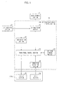
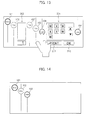
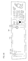
- the image forming section 6 prints an image based on the image data onto a recording sheet.
- the image forming section 6 includes a local memory 6a in which the image data is stored and a printing section 6b equipped with a laser scanning unit or the like.
- the printing section 6b prints an image, based on the image data stored in the local memory 6a, onto a recording sheet fed from a sheet feeding section (not shown).
- the image processing section 9 carries out an image processing, such as compression, extension, modification, and the like, with respect to the image data stored in the local memory 6a.
- the image data having been processed is outputted from the local memory 6a to the printing section 6b or the hard disk device 12.
- the hard disk device 12 temporarily stores the image data to be processed.
- the device control section 8 controls respective sections of the apparatus in accordance with the information stored in the management section 14 so as to send the inputted image data to the image forming section 6, thereby carrying out the printing process.
- the printing apparatus 1 of the present embodiment includes a job information display function which effectively uses a limited display area of the touch panel 4c so as to display information concerning jobs which information allows a processing order and the like of the received jobs to be confirmed (hereinafter, this information is referred to as "job information").
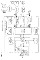
- the job information display control section 30 causes the touch panel 4c to display the job icon indicative of the presence of the job received by the job receiving section 31. If the job information display control section 30 is operated with the job icon displayed in the touch panel 4c, an information window concerning a printing job of the displayed job icon is additionally displayed.
- the job information display control section 30 includes the management section 14 and the device control section 8 which are illustrated in Fig. 1 .
- the present printing apparatus 1 has a function for causing the communication interface 7 to communicate directly with a USB memory so as to receive a job, so that function information "USB" indicating that the printing apparatus 1 serves as such a special printing apparatus is allocated to a job having been received via the communication interface 7.
- the operation detection section 38 specifies an operated job icon in accordance with a signal inputted from the touch panel 4c, and detects a manner in which the job icon has been operated, so as to send this detection result to the touch panel control section 36.
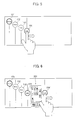
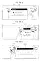
- the job icon operation manner for displaying the information window there are two types of manners: a sliding operation and a touching operation.
- the sliding operation is such that the job icon 104 is moved in parallel with its pushed. While, the touching operation is such that the job icon 104 is pushed and is released right after the pushing as in an operation carried out with respect to the job icon 104 in Fig. 8 . In case of the sliding operation, also an operation trail is sent to the touch panel control section 36.
- the display manner of the job icon is changed in accordance with the function information in this manner, so that the user can easily find what kind of job (which function information) has been received at the present stage merely by watching the touch panel 4c.
- Such display causes the job icons to be always displayed in a processing order from the upper left of the screen, so that the user can more easily find the processing status of the printing job than the arrangement in which the job icon concerning the completed job is merely deleted from the screen.
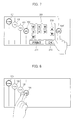
- a size of a space between the two icons 104 and 104' which space serves as a display region of the information window 201 changes according to an amount of the operation.
- a display size of the information window 201 is adjusted so as to be horizontally increased or decreased so that the display size corresponds to the region.
- the maximum size of the information window 201 may be fixed, but in case where the number of displayed job icons is large or in a similar case, all the job icons cannot be displayed when the information window 201 is opened with its maximum size. Thus, in such case, the maximum size may be made smaller. Adversely, the maximum size may be fixed and a job icon interval may be made narrower.
- Each of the direction keys 210 is used in selecting a file.
- the key 210 is operated so as to select one from the "W1, W2, ⁇ , X1, X2, ⁇ ".
- the print key 211 is used to specify a printing process. If the print key 211 is operated with a certain file selected, a printing instruction is inputted.
- the OK key 215 is used to input completion of the selection.
- the OK key 215 is operated subsequently to the operation of the print key 211 so as to validate the printing instruction.
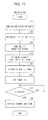
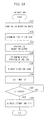
- the job receiving section 31 receives job data as a job to be processed, and the job detection section 34 detects reception of the new job. Upon detecting the reception of the new job, the job detection section 34 informs the touch panel control section 36 of this. While, the job management section 32 confirms a job reception route through which the job has been newly received (S1) so as to allocate function information.
- the touch panel control section 36 confirms a job reception status (S3) and determines a display position of the job icon concerning the newly received job (S4).
- an icon concerning a job having been processed is deleted from the screen, so that the icon display window displays only icons concerning jobs in process or jobs on standby.
- the user can instantly and clearly find current processing statuses of jobs.
- the image data in the local memory 116a is forwarded to the printing section 116b, so as to correspond to a timing at which the image data is written into the printing section 116b, with this operation repeated so as to correspond to the number of the images to be outputted.
- the multifunctional device 100 of the present embodiment includes a job information display function which effectively uses a limited display area of the touch panel 14c so as to display information concerning jobs which information allows a processing order and the like of the received jobs to be confirmed (hereinafter, this information is referred to as "job information").
- the multifunctional device 1 has a function for causing the communication interface 117 to communicate directly with a USB memory so as to receive a job, so that function information "USB" indicating that the multifunctional device 1 serves as such a special printer is allocated to a job having been received via the communication interface 117.
- function information allocated to the printing job and function information allocated to the sending job are made different from each other as “USB printing” and "USB sending”.
- the touch panel control section 136 deletes the sending instruction window 402 and the satellite icon 302' and returns the job icon 1101, having been moved, to the previous position, and displays a job icon 1103, having a circled shape indicative of "Send", diagonally below the icon 1101, as illustrated in Fig. 26 .
- the information window in the vicinity of the operated job icon as in the instruction windows 401 and 402.
- a satellite icon having the same shape as that of the operated job icon is displayed, and an information window is displayed therebwteen.
- the instruction windows 401 and 402 are displayed by carrying out a touching operation, and the information window can be displayed by carrying out any one of a touching operation and a sliding operation.
- the instruction windows 401 and 402 are displayed in a basic window in a conventional apparatus, and it is preferable that they are entirely displayed at the same time upon operating the startup icon.
- the information window is used to confirm detail information of the job, so that its display area is adjusted through the sliding operation, thereby improving the usability.
- the startup icons 301 and 302 and the job icons 1101 and 1102 are disposed diagonally from the upper left of the screen of the touch panel 114c, herein, disposed along a substantially diagonal line of the screen, and the job icons 1101 and 1102 are disposed in a reception order.
- line sections L each of which vertically extends in the screen from each of the startup icons 310 and 302 and the job icons 1101 and 1102.
- the line sections L emphasize a manner in which the icons are disposed, thereby allowing the user to watch the screen more easily.
- the display manner of the job icon concerning the newly received job is made different from those of the job icons each of which is indicative of a standby job, so that the user can easily recognize that the job icon indicates a newly received job.
- the display manner of the job icon concerning the newly received job becomes a normal display manner which shows that the job icon is indicative of a standby job.
- the job icon displayed in the screen is operated, so that the information window of the operated job icon can be displayed.
- the information displayed in the information window is predetermined in accordance with the function information of the printing job.
- the displayed information window 1201 is deleted by carrying out the touching operation with respect to any one of the icons 1104 and 1104' positioned at both sides of the information window 1201. With the deletion of the information window, also the second job icon 1104' is deleted.
- the information window whose reference numeral is 1202 is an information window indicative of function information "Printer” which information window is displayed by operating the job icon 1101 indicative of "Printer".
- an information window whose reference numeral is 1204 is an information window indicative of function information "Copy” which information window is displayed by operating the job icon 1102 indicative of "Copy”.
- the information window 1203 becomes smaller to a predetermined minimum size, and also the job icon 1104 can be slid toward the left side until the size of the information window 1203 becomes minimum.
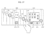
- Fig. 33 As illustrated in Fig. 33 ( Fig. 31 ), information sets indicative of file names "W1, W2, ⁇ , X1, X2, ⁇ " of all files stored in the connected USB memory 150 are displayed in the information window 1201 concerning the job indicative of the function information "USB". Further, direction keys 210, a print key 211, an OK key 215, and the like are displayed therein.
- Each of the direction keys 210 is used in selecting a file.
- the key 210 is operated so as to select one from the "W1, W2, ⁇ , X1, X2, ⁇ ".
- the print key 211 is used to specify a printing process. If the print key 211 is operated with a certain file selected, a printing instruction is inputted.
- the OK key 215 is used to input completion of the selection.
- the OK key 215 is operated subsequently to the operation of the print key 211 so as to validate the printing instruction.
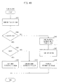
- the job receiving section 131 receives job data as a job to be processed and the newly received job is stored in the job management section 132, so that the job detection section 134 detects reception of the new job. Upon detecting the reception of the new job, the job detection section 134 informs the touch panel control section 136 of this. While, the job management section 132 confirms a job reception route through which the job has been newly received (S31) so as to allocate function information.
- an operation carried out with respect to the startup icons 301 and 302 causes instruction windows 401 and 402 to be additionally displayed, so that it is possible to display the instruction windows 401 and 402 without confusing the used even though the basic window is not always displayed. Moreover, the instruction windows 401 and 402 are additionally displayed and do not transit to other window, so that the user can keep on operating without any confusion even when the instruction windows 401 and 402 are displayed.
- the image data processing apparatus of the present invention so that the display control section displays the instruction window or the information window in a vicinity of the startup icon having been operated or the job icon having been operated.
- the image data processing apparatus of the present invention so that: in case of displaying the instruction window or the information window, the display control section displays the instruction window or the information window and moves the startup icons or the job icons, being displayed, to a periphery of the instruction window with a positional relation of the startup icons kept.
- the present multifunctional device 200 detects its status, and in case where it is detected that the multifunctional device 200 is in a status where it should report an information concerning its status to the user, an icon corresponding to the status is displayed in a touch panel 114c. Further, when the touch panel 114c is operated with the status icon displayed, an information window concerning the detected status is additionally displayed.
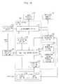
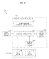
- the information display function is realized by an operation section 114, a status detection section 261, and an information display control section (display control section) 230 which are illustrated in Fig. 41.
- Fig. 41 is a functional block diagram illustrating essential portions for realizing the information display function of the present multifunctional device 200.
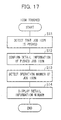
- Examples of the status which should be informed to the user include: a status in which toner scarcely remains or completely runs out; a status in which recording materials stored in a recording material cassette scarcely remain or completely run out; a status in which jam of the recording materials occurs; a status in which the apparatus is out of order; and a similar status.
- Each of them shows that the multifunctional device 200 is in a status where it should report an information concerning its status to the user as attention or warning.
- the touch panel control section 236 controls a display section 4b so as to display the status icon indicating that the status detection section 261 detects that the device is in the status which should be informed to the user. In accordance with the detected status, the touch panel control section 236 extracts a status icon, which should be displayed, from the status icon data storage section 235 so as to display the status icon in the touch panel 114c. In the status icon data storage section 235, shape data of various status icons displayed in the touch panel 114c are stored.
- the start key is not pushed even when a predetermined time period passes with keys operated by the user at the time of normal operation, it is presumed that the user is not familiar with the operation and hence has a trouble in the operation, and a content of the operation which is to be carried out by the user is presumed in accordance with the operated key, thereby displaying the presumed operation content as a help function.
- the foregoing status icon indicates that the device can show the help function.
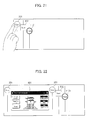
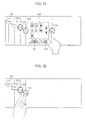
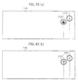
- an information window 2202 is displayed so as to follow the sliding operation. More specifically, a satellite icon 2101' having the same shape as that of the status icon 2101 is displayed in parallel to the status icon 2101 as a pair so as to follow the sliding operation, and the information window 2202 is displayed between the two icons 2101 and 2101'.
- the user may be able to find the content of the information disclosed in the information window 2201 merely by watching a part of the information window 2201 through the sliding operation carried out with respect to the status icon 2102, so that the foregoing arrangement is convenient in this case.
- a sliding operation is carried out so that the satellite icon 2102' overlaps the original status icon 2102, thereby deleting the information window 2201.
- the information window 2201 becomes smaller corresponding to an amount of the sliding operation and gradually disappears.
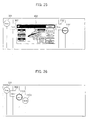
- the information windows 2201 and 2202 can be deleted when a predetermined time period passes after the information windows 2201 and 2202 are displayed. Further, each information window is automatically deleted also in case where a device status concerning the displayed information window is improved.
- the icons having been displayed on the right side of the screen are returned to their original positions at the same time as or subsequently to deletion of the information window 2202 in order to secure the display region of the information window 2202.
- the information display control section 230 causes the touch panel 114c to display a status icon indicating that the status has been detected by the status detection section 261, and the information display control section 230 causes the touch panel 114c to additionally display an information window for disclosing information concerning the status indicated by the displayed status icon when the screen is operated with the status icon displayed.
- the window may transit to another window which displays the status icon.
- the basic window or the like is not displayed in the screen which displays the status icon, so that the user does not carry out an unnecessary operation without caring occurrence of a trouble and the like.
- the status icon display window in the touch panel 114c displays a startup icon for activating the image scanning section 2, and the displayed startup icon is operated, so that a startup icon instruction window is displayed.
- An image data generation section 340 generates the image data in the device, and includes the image scanning section 2, the device control section 118 for controlling these sections, and the management section 124, all of which are illustrated in Fig. 19 .
- a control data generation section 342 In response to an instruction given from the operation section 114, a control data generation section 342 generates control data for carrying out a job process with respect to the image data scanned by the image data generation section 340. In the copy mode, the control data generation section 342 generates control data for carrying out a printing process with respect to the image data. In the sending mode of the facsimile mode and the sending mode of the scanner mode, the control data generation section 342 generates control data for carrying out a sending process with respect to the image data.
- the information display control section 363 is different from the information display control section 230 of Fig. 41 in that: the information display control section 363 includes an instruction window data storage section 333 and a job management section 332 and also includes a touch panel control section 364 provided instead of the touch panel control section 236 and includes an icon data storage section 365 provided instead of the status icon data storage section 235.
- the touch panel control section 364 is arranged in the same manner as the touch panel control section 236 in a function for displaying a status icon. As a new function, the touch panel control section 364 refers to the icon data storage section 365 and the instruction window data storage section 333 so as to cause the touch panel 114c to display a startup icon for activating the image data generation section 340 (image scanning section 2) and its instruction window. Note that, not only shape data of the status icon but also shape data of the startup icon are stored in the icon data storage section 365.
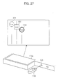
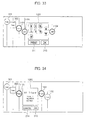
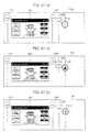
- Fig. 46 illustrates an example where the startup icons are displayed.
- icons whose reference numerals are respectively 1301 and 1302 are startup icons, and an icon whose reference numeral is 2101 is a status icon.
- the startup icons 1301 and 1302 are displayed at the left side of the screen and the status icon is displayed at the right side of the screen.
- startup icons 1301 and 1302 are always displayed as long as the multifunctional device 300 is in a condition under which the copying function and the sending function can be executed. That is, in the multifunctional device 300, the touch panel 114c displays only the startup icons 1301 and 1302 in a standby state in which no job has been received.
- each of Fig. 47(b) and Fig. 47(c) illustrates a combination of startup icons 301 and 302, an instruction window 401 in a copy mode, and status icons 2102 and 2103.
- the touch panel control section 364 causes the instruction window 1402 in the sending mode to be additionally displayed as illustrated in Fig. 48 .
- the instruction window 1402 in the sending mode allows the user to input a detail instruction for carrying out a sending operation, and a conventional apparatus generally displays this instruction window in a basic window in case where the sending mode is selected as a main mode.
- the user operates a mode switching key in the instruction window 1402, so that a sending mode, e.g., an iFAX mode in which data is sent from the communication section 110, a FAX mode in which data is sent from the FAX modem 115, or a mode in which data is sent from the communication interface 117 to the connected USB, can be selected.
- the image scanning section 2 scans image data, and the control data generation section 342 generates control data, so that a sending job in a facsimile mode, a scanner mode, a USB mode, or the like occurs.
- the sending job is sent to the job management section 332 so as to be newly managed. Further, the instruction window 1402 is deleted from the screen.
- the limited display area of the operation panel is effectively used, so that the user can more easily find a status of the apparatus, e.g., a trouble, request for maintenance, and display of an advice, as well as contents thereof.
- the image forming apparatus of the present invention so that: in case of displaying a plurality of status icons, the display control section displays the status icons so that the status icons are disposed along a diagonal line of the screen. As a result, the user can easily watch the displayed status icons.
- the object of the present invention can be realized also in such a manner that: a storage medium which computer-readably stores a program code (an executable program, an intermediate code program, and a source program) of the control program of the printing apparatus 1, the digital multifunctional devices 100, 200, and 300 is supplied to the printing apparatus 1, and the computer (or a CPU or an MPU) reads out and executes the program code stored in the storage medium.
- a storage medium which computer-readably stores a program code (an executable program, an intermediate code program, and a source program) of the control program of the printing apparatus 1
- the digital multifunctional devices 100, 200, and 300 is supplied to the printing apparatus 1
- the computer or a CPU or an MPU
- a wireless line utilizing an infrared ray used in IrDA and a remote controller (i) a wireless line which is in compliance with Bluetooth standard (registered trademark) or IEEE802.11 wireless standard, and (iii) a wireless line utilizing HDR, a mobile phone network, a satellite line, a ground wave digital network, and the like, as the transmission medium.
- the present invention can be realized by a computer data signal which is realized by electronic transmission of the program code and which is embedded in a carrier wave.
Landscapes
- Engineering & Computer Science (AREA)
- Multimedia (AREA)
- Signal Processing (AREA)
- Facsimiles In General (AREA)
- Accessory Devices And Overall Control Thereof (AREA)
- User Interface Of Digital Computer (AREA)
Priority Applications (2)
| Application Number | Priority Date | Filing Date | Title |
|---|---|---|---|
| EP15202048.3A EP3029923B1 (de) | 2007-03-09 | 2008-03-07 | Bilddatenverarbeitungsvorrichtung |
| EP16155001.7A EP3048784A1 (de) | 2007-03-09 | 2008-03-07 | Bilddatenverarbeitungsvorrichtung und bilderzeugungsvorrichtung |
Applications Claiming Priority (3)
| Application Number | Priority Date | Filing Date | Title |
|---|---|---|---|
| JP2007061078A JP4425939B2 (ja) | 2007-03-09 | 2007-03-09 | 画像データ処理装置 |
| JP2007061080A JP4391541B2 (ja) | 2007-03-09 | 2007-03-09 | 画像形成装置 |
| JP2007061079A JP4425940B2 (ja) | 2007-03-09 | 2007-03-09 | 画像データ処理装置 |
Related Child Applications (4)
| Application Number | Title | Priority Date | Filing Date |
|---|---|---|---|
| EP16155001.7A Division-Into EP3048784A1 (de) | 2007-03-09 | 2008-03-07 | Bilddatenverarbeitungsvorrichtung und bilderzeugungsvorrichtung |
| EP16155001.7A Division EP3048784A1 (de) | 2007-03-09 | 2008-03-07 | Bilddatenverarbeitungsvorrichtung und bilderzeugungsvorrichtung |
| EP15202048.3A Division EP3029923B1 (de) | 2007-03-09 | 2008-03-07 | Bilddatenverarbeitungsvorrichtung |
| EP15202048.3A Division-Into EP3029923B1 (de) | 2007-03-09 | 2008-03-07 | Bilddatenverarbeitungsvorrichtung |
Publications (3)
| Publication Number | Publication Date |
|---|---|
| EP1978722A2 true EP1978722A2 (de) | 2008-10-08 |
| EP1978722A3 EP1978722A3 (de) | 2009-03-11 |
| EP1978722B1 EP1978722B1 (de) | 2020-01-22 |
Family
ID=39710975
Family Applications (3)
| Application Number | Title | Priority Date | Filing Date |
|---|---|---|---|
| EP16155001.7A Ceased EP3048784A1 (de) | 2007-03-09 | 2008-03-07 | Bilddatenverarbeitungsvorrichtung und bilderzeugungsvorrichtung |
| EP08004289.8A Active EP1978722B1 (de) | 2007-03-09 | 2008-03-07 | Bilddatenverarbeitungsvorrichtung und Bilderzeugungsvorrichtung |
| EP15202048.3A Active EP3029923B1 (de) | 2007-03-09 | 2008-03-07 | Bilddatenverarbeitungsvorrichtung |
Family Applications Before (1)
| Application Number | Title | Priority Date | Filing Date |
|---|---|---|---|
| EP16155001.7A Ceased EP3048784A1 (de) | 2007-03-09 | 2008-03-07 | Bilddatenverarbeitungsvorrichtung und bilderzeugungsvorrichtung |
Family Applications After (1)
| Application Number | Title | Priority Date | Filing Date |
|---|---|---|---|
| EP15202048.3A Active EP3029923B1 (de) | 2007-03-09 | 2008-03-07 | Bilddatenverarbeitungsvorrichtung |
Country Status (2)
| Country | Link |
|---|---|
| US (1) | US8325354B2 (de) |
| EP (3) | EP3048784A1 (de) |
Cited By (2)
| Publication number | Priority date | Publication date | Assignee | Title |
|---|---|---|---|---|
| CN101815144A (zh) * | 2009-02-25 | 2010-08-25 | 柯尼卡美能达商用科技株式会社 | 显示管理系统 |
| EP3358815A1 (de) * | 2017-02-07 | 2018-08-08 | Kabushiki Kaisha Toshiba | Bildverarbeitungsvorrichtung und informationsbereitstellungsverfahren |
Families Citing this family (20)
| Publication number | Priority date | Publication date | Assignee | Title |
|---|---|---|---|---|
| JP4666027B2 (ja) * | 2008-08-29 | 2011-04-06 | コニカミノルタビジネステクノロジーズ株式会社 | 画像処理装置およびサーバ |
| JP4775864B2 (ja) * | 2008-09-29 | 2011-09-21 | 株式会社沖データ | 画像形成装置 |
| JP2010147790A (ja) * | 2008-12-18 | 2010-07-01 | Canon Inc | 装置、方法、プログラム及び記憶媒体 |
| KR101533280B1 (ko) * | 2009-01-09 | 2015-07-09 | 삼성전자주식회사 | 복합 디바이스의 콘텐트 재생 방법 및 장치 |
| JP2010224627A (ja) * | 2009-03-19 | 2010-10-07 | Sharp Corp | プリントシステム |
| CN102202147A (zh) * | 2010-03-26 | 2011-09-28 | 株式会社东芝 | 图像形成装置、图像形成处理系统以及图像形成处理方法 |
| US9268478B2 (en) * | 2010-03-31 | 2016-02-23 | Honeywell International Inc. | Touch screen system for use with a commanded system requiring high integrity |
| JP5599038B2 (ja) * | 2010-05-13 | 2014-10-01 | キヤノン株式会社 | 情報処理装置及び方法、並びにプログラム |
| JP5160607B2 (ja) | 2010-09-22 | 2013-03-13 | シャープ株式会社 | 複合機 |
| JP2012075025A (ja) | 2010-09-29 | 2012-04-12 | Kyocera Mita Corp | 操作装置及び操作方法 |
| JP5148677B2 (ja) | 2010-10-08 | 2013-02-20 | シャープ株式会社 | 複合機 |
| JP5772071B2 (ja) * | 2011-03-07 | 2015-09-02 | 富士通株式会社 | 作業手順表示装置 |
| JP5318907B2 (ja) * | 2011-05-13 | 2013-10-16 | シャープ株式会社 | 複合機、複合機制御システム、複合機の制御方法、プログラムおよびその記録媒体 |
| JP6055734B2 (ja) * | 2012-09-26 | 2016-12-27 | 京セラドキュメントソリューションズ株式会社 | 表示入力装置及びこれを備えた画像形成装置 |
| USD792466S1 (en) * | 2015-08-20 | 2017-07-18 | S-Printing Solution Co., Ltd. | Display screen or portion thereof with graphical user interface |
| JP6827821B2 (ja) * | 2017-01-24 | 2021-02-10 | キヤノン株式会社 | 情報処理装置及びその制御方法、並びにプログラム |
| JP6809342B2 (ja) * | 2017-03-31 | 2021-01-06 | ブラザー工業株式会社 | 印刷制御プログラム、印刷制御装置および印刷制御方法 |
| JP7071106B2 (ja) * | 2017-12-07 | 2022-05-18 | キヤノン株式会社 | 画像形成装置、画像形成装置の制御方法 |
| JP7119408B2 (ja) * | 2018-02-15 | 2022-08-17 | コニカミノルタ株式会社 | 画像処理装置、画面取扱い方法、およびコンピュータプログラム |
| US12027163B2 (en) * | 2020-07-27 | 2024-07-02 | Samsung Electronics Co., Ltd. | Electronic device and operation method thereof |
Citations (4)
| Publication number | Priority date | Publication date | Assignee | Title |
|---|---|---|---|---|
| JP2000092257A (ja) | 1998-09-16 | 2000-03-31 | Konica Corp | 複写装置 |
| JP2001154773A (ja) | 1999-11-26 | 2001-06-08 | Sharp Corp | 情報表示システムおよび画像形成装置 |
| JP2002344682A (ja) | 2001-05-21 | 2002-11-29 | Sharp Corp | 画像処理装置 |
| JP2005102044A (ja) | 2003-09-26 | 2005-04-14 | Kyocera Mita Corp | 画像形成装置 |
Family Cites Families (15)
| Publication number | Priority date | Publication date | Assignee | Title |
|---|---|---|---|---|
| JPH04180458A (ja) * | 1990-11-15 | 1992-06-26 | Fuji Xerox Co Ltd | ファクシミリ装置 |
| JPH04296965A (ja) | 1991-01-10 | 1992-10-21 | Hitachi Ltd | プログラムの入力方法 |
| US5422993A (en) * | 1991-12-17 | 1995-06-06 | International Business Machines Corporation | Method and system for performing direct manipulation operations in a computer system |
| US5706411A (en) * | 1992-11-09 | 1998-01-06 | Microsoft Corporation | Printer status user interface and methods relating thereto |
| US5950045A (en) * | 1997-06-20 | 1999-09-07 | Sharp Kabushiki Kaisha | Input device |
| JP3558853B2 (ja) | 1998-02-17 | 2004-08-25 | シャープ株式会社 | ガイダンス情報表示装置 |
| JP2003032413A (ja) | 2001-07-12 | 2003-01-31 | Fuji Xerox Co Ltd | ジョブ表示装置およびその方法 |
| JP4183967B2 (ja) | 2002-04-16 | 2008-11-19 | シャープ株式会社 | 情報提供方法および情報提供システム |
| JP2004054839A (ja) * | 2002-07-24 | 2004-02-19 | Minolta Co Ltd | ファイルアイコンの表示プログラム |
| JP2005045370A (ja) | 2003-07-23 | 2005-02-17 | Kyocera Mita Corp | 画像形成装置 |
| US20050177799A1 (en) * | 2004-02-05 | 2005-08-11 | Knight Juliet F. | Method of associating an icon with a temporary profile |
| US7424236B2 (en) * | 2004-10-25 | 2008-09-09 | Konica Minolta Business Technologies, Inc. | Controlling method for image forming apparatus |
| US20060242593A1 (en) * | 2005-04-26 | 2006-10-26 | Sharp Laboratories Of America, Inc. | Printer emoticon detector & converter |
| US20070038946A1 (en) * | 2005-08-15 | 2007-02-15 | Grieshaber Charles E | Systems, methods and devices for controlling a multifunctional product using a scriptable user interface |
| US7667865B2 (en) * | 2006-02-06 | 2010-02-23 | Xerox Corporation | Mobile device-enabled secure release of print jobs |
-
2008
- 2008-03-05 US US12/073,442 patent/US8325354B2/en not_active Expired - Fee Related
- 2008-03-07 EP EP16155001.7A patent/EP3048784A1/de not_active Ceased
- 2008-03-07 EP EP08004289.8A patent/EP1978722B1/de active Active
- 2008-03-07 EP EP15202048.3A patent/EP3029923B1/de active Active
Patent Citations (4)
| Publication number | Priority date | Publication date | Assignee | Title |
|---|---|---|---|---|
| JP2000092257A (ja) | 1998-09-16 | 2000-03-31 | Konica Corp | 複写装置 |
| JP2001154773A (ja) | 1999-11-26 | 2001-06-08 | Sharp Corp | 情報表示システムおよび画像形成装置 |
| JP2002344682A (ja) | 2001-05-21 | 2002-11-29 | Sharp Corp | 画像処理装置 |
| JP2005102044A (ja) | 2003-09-26 | 2005-04-14 | Kyocera Mita Corp | 画像形成装置 |
Cited By (2)
| Publication number | Priority date | Publication date | Assignee | Title |
|---|---|---|---|---|
| CN101815144A (zh) * | 2009-02-25 | 2010-08-25 | 柯尼卡美能达商用科技株式会社 | 显示管理系统 |
| EP3358815A1 (de) * | 2017-02-07 | 2018-08-08 | Kabushiki Kaisha Toshiba | Bildverarbeitungsvorrichtung und informationsbereitstellungsverfahren |
Also Published As
| Publication number | Publication date |
|---|---|
| US20090296131A1 (en) | 2009-12-03 |
| EP3029923A1 (de) | 2016-06-08 |
| EP1978722A3 (de) | 2009-03-11 |
| US8325354B2 (en) | 2012-12-04 |
| EP1978722B1 (de) | 2020-01-22 |
| EP3048784A1 (de) | 2016-07-27 |
| EP3029923B1 (de) | 2017-11-22 |
Similar Documents
| Publication | Publication Date | Title |
|---|---|---|
| EP1978722B1 (de) | Bilddatenverarbeitungsvorrichtung und Bilderzeugungsvorrichtung | |
| JP5075240B2 (ja) | 操作装置、画像処理装置、及び、表示方法 | |
| US8228343B2 (en) | Image processing apparatus, computer program product, and preview image displaying method | |
| CN101262537B (zh) | 图像数据处理装置和图像形成装置 | |
| JP2008276693A (ja) | 画像形成装置及びプログラム | |
| JPH10271260A (ja) | 多機能マシンに対して適切なユーザーインターフェイスを表示する方法及びシステム | |
| JP4391541B2 (ja) | 画像形成装置 | |
| JP2024054148A (ja) | 印刷装置 | |
| CN104954626A (zh) | 传输装置以及传输装置的控制方法 | |
| JP2022041701A (ja) | 画像形成装置、画像形成装置の制御方法及びプログラム | |
| US11700345B2 (en) | Image processing apparatus, image processing method, and storage medium for displaying a function screen | |
| US20100103456A1 (en) | Apparatus and system of image processing apparatus, and medium storing image processing control program | |
| JP2018158529A (ja) | 画像処理装置、システムおよびプログラム | |
| US20060256375A1 (en) | Image forming apparatus and method of controlling user interface of image forming apparatus | |
| JP2010023367A (ja) | 画像形成装置及びその制御プログラム | |
| JP5459260B2 (ja) | 画像形成装置、設定方法および設定プログラム | |
| JP4885256B2 (ja) | 画像データ処理装置 | |
| US8335995B2 (en) | Image forming apparatus, display switching control method, and computer readable medium storing program therefor | |
| JP2008225708A (ja) | 画像データ処理装置 | |
| JP6780400B2 (ja) | 画像処理装置および画像形成装置 | |
| US20220166891A1 (en) | Information processing apparatus, image processing apparatus, method for controlling information processing apparatus, and recording medium | |
| JP2018045556A (ja) | 処理装置および画像形成装置 | |
| JP2020068399A (ja) | 情報処理装置、情報処理装置における設定制御プログラムおよび設定制御方法 | |
| US10567610B2 (en) | Image forming apparatus that executes correlated operation correlated with document placement on document placement plate or contact glass | |
| JP5804239B2 (ja) | 電子装置、画像形成装置、及びプログラム |
Legal Events
| Date | Code | Title | Description |
|---|---|---|---|
| PUAI | Public reference made under article 153(3) epc to a published international application that has entered the european phase |
Free format text: ORIGINAL CODE: 0009012 |
|
| AK | Designated contracting states |
Kind code of ref document: A2 Designated state(s): AT BE BG CH CY CZ DE DK EE ES FI FR GB GR HR HU IE IS IT LI LT LU LV MC MT NL NO PL PT RO SE SI SK TR |
|
| AX | Request for extension of the european patent |
Extension state: AL BA MK RS |
|
| PUAL | Search report despatched |
Free format text: ORIGINAL CODE: 0009013 |
|
| AK | Designated contracting states |
Kind code of ref document: A3 Designated state(s): AT BE BG CH CY CZ DE DK EE ES FI FR GB GR HR HU IE IS IT LI LT LU LV MC MT NL NO PL PT RO SE SI SK TR |
|
| AX | Request for extension of the european patent |
Extension state: AL BA MK RS |
|
| 17P | Request for examination filed |
Effective date: 20090525 |
|
| 17Q | First examination report despatched |
Effective date: 20090728 |
|
| AKX | Designation fees paid |
Designated state(s): DE GB |
|
| STAA | Information on the status of an ep patent application or granted ep patent |
Free format text: STATUS: EXAMINATION IS IN PROGRESS |
|
| GRAP | Despatch of communication of intention to grant a patent |
Free format text: ORIGINAL CODE: EPIDOSNIGR1 |
|
| STAA | Information on the status of an ep patent application or granted ep patent |
Free format text: STATUS: GRANT OF PATENT IS INTENDED |
|
| INTG | Intention to grant announced |
Effective date: 20190917 |
|
| GRAS | Grant fee paid |
Free format text: ORIGINAL CODE: EPIDOSNIGR3 |
|
| GRAA | (expected) grant |
Free format text: ORIGINAL CODE: 0009210 |
|
| STAA | Information on the status of an ep patent application or granted ep patent |
Free format text: STATUS: THE PATENT HAS BEEN GRANTED |
|
| AK | Designated contracting states |
Kind code of ref document: B1 Designated state(s): DE GB |
|
| REG | Reference to a national code |
Ref country code: GB Ref legal event code: FG4D |
|
| REG | Reference to a national code |
Ref country code: DE Ref legal event code: R096 Ref document number: 602008062032 Country of ref document: DE |
|
| REG | Reference to a national code |
Ref country code: DE Ref legal event code: R097 Ref document number: 602008062032 Country of ref document: DE |
|
| PLBE | No opposition filed within time limit |
Free format text: ORIGINAL CODE: 0009261 |
|
| STAA | Information on the status of an ep patent application or granted ep patent |
Free format text: STATUS: NO OPPOSITION FILED WITHIN TIME LIMIT |
|
| 26N | No opposition filed |
Effective date: 20201023 |
|
| PGFP | Annual fee paid to national office [announced via postgrant information from national office to epo] |
Ref country code: DE Payment date: 20250319 Year of fee payment: 18 |
|
| PGFP | Annual fee paid to national office [announced via postgrant information from national office to epo] |
Ref country code: GB Payment date: 20250319 Year of fee payment: 18 |