EP1941981A1 - Verfahren zur formung einer schreibspur auf einem substrat aus sprödem material und vorrichtung zur formung einer schreibspur - Google Patents
Verfahren zur formung einer schreibspur auf einem substrat aus sprödem material und vorrichtung zur formung einer schreibspur Download PDFInfo
- Publication number
- EP1941981A1 EP1941981A1 EP06822300A EP06822300A EP1941981A1 EP 1941981 A1 EP1941981 A1 EP 1941981A1 EP 06822300 A EP06822300 A EP 06822300A EP 06822300 A EP06822300 A EP 06822300A EP 1941981 A1 EP1941981 A1 EP 1941981A1
- Authority
- EP
- European Patent Office
- Prior art keywords
- scribe line
- brittle material
- created
- creating
- crack
- Prior art date
- Legal status (The legal status is an assumption and is not a legal conclusion. Google has not performed a legal analysis and makes no representation as to the accuracy of the status listed.)
- Withdrawn
Links
Images


Classifications
-
- C—CHEMISTRY; METALLURGY
- C03—GLASS; MINERAL OR SLAG WOOL
- C03B—MANUFACTURE, SHAPING, OR SUPPLEMENTARY PROCESSES
- C03B33/00—Severing cooled glass
- C03B33/09—Severing cooled glass by thermal shock
-
- B—PERFORMING OPERATIONS; TRANSPORTING
- B28—WORKING CEMENT, CLAY, OR STONE
- B28D—WORKING STONE OR STONE-LIKE MATERIALS
- B28D1/00—Working stone or stone-like materials, e.g. brick, concrete or glass, not provided for elsewhere; Machines, devices, tools therefor
- B28D1/22—Working stone or stone-like materials, e.g. brick, concrete or glass, not provided for elsewhere; Machines, devices, tools therefor by cutting, e.g. incising
- B28D1/221—Working stone or stone-like materials, e.g. brick, concrete or glass, not provided for elsewhere; Machines, devices, tools therefor by cutting, e.g. incising by thermic methods
-
- B—PERFORMING OPERATIONS; TRANSPORTING
- B28—WORKING CEMENT, CLAY, OR STONE
- B28D—WORKING STONE OR STONE-LIKE MATERIALS
- B28D5/00—Fine working of gems, jewels, crystals, e.g. of semiconductor material; apparatus or devices therefor
- B28D5/0005—Fine working of gems, jewels, crystals, e.g. of semiconductor material; apparatus or devices therefor by breaking, e.g. dicing
- B28D5/0011—Fine working of gems, jewels, crystals, e.g. of semiconductor material; apparatus or devices therefor by breaking, e.g. dicing with preliminary treatment, e.g. weakening by scoring
-
- C—CHEMISTRY; METALLURGY
- C03—GLASS; MINERAL OR SLAG WOOL
- C03B—MANUFACTURE, SHAPING, OR SUPPLEMENTARY PROCESSES
- C03B33/00—Severing cooled glass
- C03B33/02—Cutting or splitting sheet glass or ribbons; Apparatus or machines therefor
- C03B33/023—Cutting or splitting sheet glass or ribbons; Apparatus or machines therefor the sheet or ribbon being in a horizontal position
- C03B33/027—Scoring tool holders; Driving mechanisms therefor
-
- C—CHEMISTRY; METALLURGY
- C03—GLASS; MINERAL OR SLAG WOOL
- C03B—MANUFACTURE, SHAPING, OR SUPPLEMENTARY PROCESSES
- C03B33/00—Severing cooled glass
- C03B33/02—Cutting or splitting sheet glass or ribbons; Apparatus or machines therefor
- C03B33/023—Cutting or splitting sheet glass or ribbons; Apparatus or machines therefor the sheet or ribbon being in a horizontal position
- C03B33/033—Apparatus for opening score lines in glass sheets
-
- C—CHEMISTRY; METALLURGY
- C03—GLASS; MINERAL OR SLAG WOOL
- C03B—MANUFACTURE, SHAPING, OR SUPPLEMENTARY PROCESSES
- C03B33/00—Severing cooled glass
- C03B33/09—Severing cooled glass by thermal shock
- C03B33/091—Severing cooled glass by thermal shock using at least one focussed radiation beam, e.g. laser beam
-
- H—ELECTRICITY
- H10—SEMICONDUCTOR DEVICES; ELECTRIC SOLID-STATE DEVICES NOT OTHERWISE PROVIDED FOR
- H10P—GENERIC PROCESSES OR APPARATUS FOR THE MANUFACTURE OR TREATMENT OF DEVICES COVERED BY CLASS H10
- H10P95/00—Generic processes or apparatus for manufacture or treatments not covered by the other groups of this subclass
-
- H—ELECTRICITY
- H10—SEMICONDUCTOR DEVICES; ELECTRIC SOLID-STATE DEVICES NOT OTHERWISE PROVIDED FOR
- H10P—GENERIC PROCESSES OR APPARATUS FOR THE MANUFACTURE OR TREATMENT OF DEVICES COVERED BY CLASS H10
- H10P72/00—Handling or holding of wafers, substrates or devices during manufacture or treatment thereof
- H10P72/04—Apparatus for manufacture or treatment
- H10P72/0428—Apparatus for mechanical treatment or grinding or cutting
-
- Y—GENERAL TAGGING OF NEW TECHNOLOGICAL DEVELOPMENTS; GENERAL TAGGING OF CROSS-SECTIONAL TECHNOLOGIES SPANNING OVER SEVERAL SECTIONS OF THE IPC; TECHNICAL SUBJECTS COVERED BY FORMER USPC CROSS-REFERENCE ART COLLECTIONS [XRACs] AND DIGESTS
- Y02—TECHNOLOGIES OR APPLICATIONS FOR MITIGATION OR ADAPTATION AGAINST CLIMATE CHANGE
- Y02P—CLIMATE CHANGE MITIGATION TECHNOLOGIES IN THE PRODUCTION OR PROCESSING OF GOODS
- Y02P40/00—Technologies relating to the processing of minerals
- Y02P40/50—Glass production, e.g. reusing waste heat during processing or shaping
- Y02P40/57—Improving the yield, e-g- reduction of reject rates
Definitions
- the present invention relates to a method for creating a scribe line on a substrate when a single substrate made of a brittle material, such as glass, ceramic, which is a sintered material, single crystal silicon, semiconductor wafer or ceramic substrate, or a mother substrate made of single substrates which are pasted together, mainly, is cut.
- a brittle material such as glass, ceramic, which is a sintered material, single crystal silicon, semiconductor wafer or ceramic substrate, or a mother substrate made of single substrates which are pasted together, mainly, is cut.
- a method for cutting a substrate according to which a rotational blade, such as a cutter wheel, is rolled over the surface of the substrate and a crack is created along the line in the direction of the thickness, and thus the substrate is cut is widely used.
- a scribe line is created with a cutter wheel, the cutter wheel is rolled over the surface of the brittle substrate while pressing with a strong force in order to create the scribe line, and therefore, various inconveniences are sometimes caused.
- a scribe line is created with a cutter wheel, for example, a horizontal crack is sometimes created in addition to a vertical crack which runs in the direction of the thickness.
- cullet is created only when the initial crack (trigger) is created at an end of the substrate with a cutter wheel, and thus, the amount of created cullet can be reduced in comparison with when scribe lines are created using a cutter wheel.
- the numeral value for the strength on the end surfaces after breaking using a breaking apparatus can be made higher.
- Such products as displays for personal computers and flat TV's where a flat display is used which have a screen of which the display area is large in scale are preferred, and as a result, mother substrates tend to have a greater area, and it is required for the straightness of the created scribe lines to be much more stable.
- the substrates of portable terminal apparatuses such as portable phones and game consoles, are required to be thinner because they are portable, and such quality as to have higher strength on the end surfaces is required.
- conventional scribing using a blade and methods for scribing using a laser are unable to meet requirements in the market, and thus, cannot meet with the strict requirements for the various qualities described above.
- a main object of the present invention is to provide a method where both laser scribing and scribing with a cutter are used so that the characteristics of the two are combined in the best manner, that is to say, a method for creating a scribe line on a brittle substrate material where the line along which the substrate is scribed is scribed with a laser, and after that, the scribe line is traced with a cutter so that the vertical crack becomes deep, and thus the straightness is high and excellent cut surfaces are provided, as well as an apparatus for use in this method.
- the present invention provides the following technical means. That is to say, the method for creating a scribe line on a brittle material substrate according to the present invention is characterized by being provided with the step of heating the surface of a brittle material substrate along a line along which a scribe line is created at a temperature lower than the point at which the above described brittle material substrate softens; the step of creating a crack having a first depth by cooling the heated region immediately after heating; and the subsequent step of creating a second crack which is deeper than the first depth within the substrate by moving a cutter over the surface of the substrate along the scribe line in a pressed state.
- the apparatus for creating a scribe line on a brittle material substrate is formed so as to be provided with: a fist crack creating means made up of a laser beam scanning means for scanning the surface of a brittle material substrate along a line along which a scribe line is created with a laser beam while heating the substrate with the laser at a temperature lower than the point at which the above described brittle material substrate softens, and a cooling means for cooling the heated region immediately after heating using said laser beam; and a means for moving a cutter in a pressed state for moving a cutter along the scribe line in a pressed state so that a crack which is deeper than the first crack is created in the substrate.
- a laser beam as those usually used for scribing a brittle material substrate may be used, and it is preferable to use such laser beams as excimer lasers, YAG lasers, carbonic acid gas lasers or carbon monoxide lasers.
- laser beams as excimer lasers, YAG lasers, carbonic acid gas lasers or carbon monoxide lasers.
- a carbonic acid gas laser due to the high efficiency in terms of energy absorption and for economical reasons.
- the substrate is cooled after being irradiated with a laser beam, and after that, the crack is deepened using a cutter, and therefore, the brittle material substrate is divided with precision, providing high quality on the cut surfaces, and at the same time, the substrate can be easily broken with a light load.
- the cutter is moved over the surface of the substrate in a pressed state after laser scribing, and therefore, a crack which is deeper than cracks created only through laser scribing can be created with a light load for pressing, and excellent effects can be gained, such that microscopic glass cullet is prevented from being created, and thus, various problems can be avoided, and at the same time, the wear of the cutter can be reduced, so that the life is prolonged and the cost is reduced.
- a highly straight scribe line is created with little cullet created through the initial laser scribing, and after that, a load is applied to this scribe line with a cutter so that the depth of the crack, which is shallow after only laser scribing, can be increased and a deeper crack gained, and thus, specific effects which cannot be observed in the prior art can be gained, such that stability is secured in the breaking operation, which contributes to maintaining high quality on the cut surfaces after breaking.
- the means for pressing the substrate with a cutter also works as a means for creating an initial crack, and therefore, no additional apparatus is necessary.
- an electrode terminal process for a liquid crystal panel for example, usually scribe lines are created with a blade, and then so-called marginal portions are cut off using a breaking machine, and breaking cannot be carried out with precision, due to the small width of the marginal portions, but breaking can be carried out with precision according to the present invention.
- a deep crack can be created with a blade through laser scribing without reducing the speed of scanning with the laser, and therefore, effects can be gained, such that liquid crystal panels can be mass produced without changing the so-called tact time.
- the above described cutter it is preferable for the above described cutter to be formed as a rotating blade which rolls over a brittle substrate, such as a cutter wheel.
- a brittle substrate such as a cutter wheel.
- a cutter as a non-rotational blade which slides over a brittle material substrate.
- the structure of the cutter portion can be a simple mechanism, and formed at low cost.
- the means for moving a cutter in a pressed state can also be used as a means for creating an initial crack (trigger), and thus, the apparatus can be simplified, and in addition, panels of which the specifications have been changed so that the conditions for scribing are greatly different can be dealt with by switching the program.
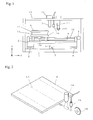
- Fig 1 is a schematic diagram showing the configuration of the apparatus for creating a scribe line according to one embodiment of the present invention as viewed from the front.
- a slide table 2 which reciprocates in the front-rear direction in Fig 1 (hereinafter referred to as Y direction) is provided along a pair of guide rails 3 and 4 which are placed parallel on a horizontal base 1.
- a screw 5 is placed in the front-rear direction between the two-guide rails 3 and 4, and this screw 5 is screwed into a stay 6 which is fixed to the above described slide table 2, and the slide table 2 is formed in such a manner as to reciprocate in the Y direction along the guide rails 3 and 4 when the screw 5 is rotated forward and backward by a motor (not shown).
- a horizontal support 7 is arranged on the slide table 2 in such a manner as to reciprocate along a guide rail 8 in the left-right direction in Fig 1 (hereinafter referred to as X direction).
- a screw 10 which is rotated by a motor 9 penetrates through and is screwed into a stay 10 which is fixed to the support 7 so that the support 7 reciprocates in the X direction along the guide rail 8 when the screw 10 rotates forward and backward.
- a rotational table 12 which is rotated by a rotation mechanism 11 is provided on the support 7, and a brittle material substrate A, such as a glass substrate, which is an object to be cut (hereinafter simply referred to as glass substrate) is attached to this rotational table 12 in a horizontal state.
- the rotation mechanism 11 is formed so as to rotate the rotational table 12 around a vertical axis, and can rotate the table to any rotation angle from the reference point.
- the glass substrate A, which is the object to be cut is fixed to the rotational table 12 by means of, for example, a suction chuck.
- An optical holder 14 which is connected to a laser oscillator 13 is supported by an attachment frame 15 above the rotational table.
- the optical holder 14 makes it so that the laser oscillator 13 radiates an elliptical laser spot S1 which extends in a predetermined direction onto the glass substrate A.
- a cooling nozzle 16 is provided in the attachment frame 15 in close proximity to the optical holder 14.
- a cooling medium such as cooling water, H gas or carbonic acid gas, is sprayed against the glass substrate from this cooling nozzle 16. This cooling medium is sprayed in a location in close proximity to an end portion of the laser spot S1 which is radiated onto the glass substrate A by the optical holder 14 in advance in the longitudinal direction so as to create a cool spot S2 on the surface of the glass substrate A.
- a cutter wheel 18 for creating a deeper crack in the glass substrate A is attached to the attachment frame 15 via an upward-downward movement adjusting mechanism 17.
- This cutter wheel 18 is made of sintered diamond or a hard metal, and provided with a ridgeline portion in V form of which the vertex is the blade around the outer periphery, and the path when the blade rotates is along the scribe line created through laser scribing. That is to say, the path when the blade of the cutter wheel 18 rotates is on a line connecting the laser spot S1 which is radiated onto the glass substrate A by the optical holder 14 and the cool spot S2 which is sprayed from the cooling nozzle 16.
- This cutter wheel 18 is driven by a drive mechanism including a motor, not shown, so that the force pressing against the glass substrate A can be finely adjusted by the upward-downward movement adjusting mechanism 17.
- Positioning of the above described slide table 2 and the support 12, control of the laser oscillator 13 and the cooling nozzle 16, and positioning (force pressing against glass substrate A) and rotation control of the cutter wheel 18 are controlled by a computer control portion, not shown.
- a scribe line is created on the glass substrate A using the above described apparatus for creating a scribe line
- the size of the glass substrate A which is to be divided into pieces of a predetermined size, the location where scribe lines are to be created and the force for pressing the cutter wheel 18 against the glass substrate A are inputted.
- the glass substrate A is fixed to the rotational table 12 using, for example, a suction means.
- the glass substrate A is moved in the direction along the line L1 along which a scribe line is created, that is to say, in the direction to the right from the location in Fig 1 , relative to the attachment frame 15 together with the slide table 2.
- the longitudinal direction of the elliptical laser spot radiated by the optical holder 14 becomes the direction along the line L1 along which a scribe line is formed on the glass substrate A.
- Figs 2 to 4 are schematic perspective diagrams for illustrating the operation for creating a scribe line on the glass substrate A; Fig 2 shows the state before a scribe line is created.
- the location of the glass substrate A in this Fig 2 corresponds to the location of the glass substrate in Fig 1 .
- the glass substrate A is moved from the location in Fig 2 until the end is located beneath the cutter wheel 18, the cutter wheel 18 is lowered by the upward-downward movement adjusting mechanism 17, and the glass substrate A is moved slightly in the direction of the arrow while the end of the glass substrate A makes contact with the cutter wheel so that an initial crack is created at the end of the glass substrate A.
- the glass substrate A is once returned to its original location (location in Fig 2 ), and the glass substrate A is again moved in the direction of the arrow so that the elliptical laser spot S1 is radiated along the line L1 along which a scribe line is formed, as shown in Fig 3 .
- the design is such that the laser spot S1 is a long ellipsis having, for example, a long diameter of 30.0 mm and a short diameter of 1.0 mm, and the long axis coincides with the line L1 along which a scribe line is created.
- the temperature at which the laser spot S1 is heated is set to a temperature lower than the point at which the glass substrate A softens. As a result, the surface of the glass substrate A which is irradiated with the laser spot S1 is heated without melting.
- the glass substrate A is further slid in the direction of the arrow, and a cooling medium is sprayed from the cooling nozzle 16.
- This cooling medium is sprayed along the line L1 along which a scribe line is created with intervals of, for example, 2.5 mm in the direction of the long axis of the radiated laser spot S1.
- compression stress is generated in the region heated by the laser spot S1 and tensile stress is generated in the cool spot S2 cooled by the cooling medium.
- microscopic cracks are created in sequence in the glass substrate a along the line L1 along which a scribe line is created.
- the glass substrate A is slid in the direction of the arrow, and thus, a deeper crack is created using the cutter wheel 18, which rolls along the scribe line on the glass substrate A in a pressed state.
- the load with which the cutter wheel 18 is pressed against the glass substrate A is approximately 3 N, as it is possible for such a light load for pressing to create a crack B as that shown in Fig 5(c) in the lower portion of the scribe line L2, so that the substrate can be divided with a light load.
- a deeper crack is created by means of the cutter wheel 18 and the substrate is cut from this crack when the substrate is cut, and thus, high quality can be gained on the cut surfaces.
- a scribe line for changing the plasticity can be created on the surface of the glass substrate, and as a result, this scribe line makes it possible to cut the substrate along a straight line in the same manner as described above.
- the substrate when the substrate is cut, the substrate can be divided with a light load in comparison with the case where the scribe line is created using only a laser beam.
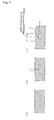
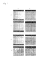
- Figs 7(a) to 8(d) are cross sectional photographs and plan photographs showing the state of the scribe lines created under various conditions for pressing with a cutter wheel in the above described apparatus for creating a scribed line.
- the apparatus used was a type MS500 made by Mitsuboshi Diamond Industrial Co., Ltd.
- the cutter wheel used was a type CW-T 2 ⁇ 120 ° V770 made by Mitsuboshi Diamond Industrial Co., Ltd..
- the substrates used were Eagle 2000 made by Corning Incorporated having a thickness of 0.7 mm.
- the cross sectional photograph of Fig 7(a) shows a surface cut only through laser scribing
- the cross sectional photograph of Fig 7(b) shows a surface cut through laser scribing and using a cutter wheel with a load for pressing of 2 N
- the cross sectional photograph of Fig 7(c) shows a surface cut through laser scribing and using a cutter wheel with a load for pressing of 4 N
- the cross sectional photograph of Fig 7(d) shows a surface cut through laser scribing and using a cutter wheel with a load for pressing of 10 N.
- ⁇ 1000 right column
- ⁇ 200 left column
- the plan photograph of Fig 8(a) shows a surface cut using a cutter wheel with a load for pressing of 2 N after laser scribing
- the plan photograph of Fig 8(b) shows a surface cut using a cutter wheel with a load for pressing of 4 N after laser scribing
- the plan photograph of Fig 8(c) shows a surface cut using a cutter wheel with a load for pressing of 6 N after laser scribing
- the plan photograph of Fig 8(d) shows a surface cut using a cutter wheel with a load for pressing of 8 N after laser scribing.
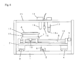
- the cutter for creating a scribe line L2 is a rotating blade in wheel form, as shown in Fig 6 , it is possible to create the scribe line with a non-rotational blade 18a which slides over the glass substrate A in a set location.
- the glass substrate A is slid relative to the optical holder 14, the cooling nozzle 16 and the cutter wheel 18, it is, of course, possible for the optical holder 14, the cooling nozzle 16 and the cutter wheel 18 to be moved relative to the glass substrate A in the configuration instead.
- the method and the apparatus for creating a scribe line according to the present invention can be used to create a scribe line on glass, ceramic, which is a sintered material, single crystal silicon, semiconductor wafer and ceramic substrate, and in addition, on liquid crystal display substrates, transmission liquid crystal display substrates, organic EL element substrates and PDP (plasma display panel) substrates where glass substrates are pasted together, and reflective liquid crystal display substrates where a glass substrate and a silicon substrate are pasted together.
Landscapes
- Engineering & Computer Science (AREA)
- Chemical & Material Sciences (AREA)
- Materials Engineering (AREA)
- Physics & Mathematics (AREA)
- Organic Chemistry (AREA)
- Mechanical Engineering (AREA)
- Thermal Sciences (AREA)
- Health & Medical Sciences (AREA)
- Optics & Photonics (AREA)
- Toxicology (AREA)
- Mining & Mineral Resources (AREA)
- Processing Of Stones Or Stones Resemblance Materials (AREA)
- Re-Forming, After-Treatment, Cutting And Transporting Of Glass Products (AREA)
Applications Claiming Priority (2)
| Application Number | Priority Date | Filing Date | Title |
|---|---|---|---|
| JP2005313931 | 2005-10-28 | ||
| PCT/JP2006/321324 WO2007049668A1 (ja) | 2005-10-28 | 2006-10-26 | 脆性材料基板のスクライブライン形成方法およびスクライブライン形成装置 |
Publications (2)
| Publication Number | Publication Date |
|---|---|
| EP1941981A1 true EP1941981A1 (de) | 2008-07-09 |
| EP1941981A4 EP1941981A4 (de) | 2014-01-01 |
Family
ID=37967778
Family Applications (1)
| Application Number | Title | Priority Date | Filing Date |
|---|---|---|---|
| EP06822300.7A Withdrawn EP1941981A4 (de) | 2005-10-28 | 2006-10-26 | Verfahren zur formung einer schreibspur auf einem substrat aus sprödem material und vorrichtung zur formung einer schreibspur |
Country Status (7)
| Country | Link |
|---|---|
| US (1) | US20090230102A1 (de) |
| EP (1) | EP1941981A4 (de) |
| JP (1) | JP4890462B2 (de) |
| KR (1) | KR101140164B1 (de) |
| CN (1) | CN101296787B (de) |
| TW (1) | TWI413622B (de) |
| WO (1) | WO2007049668A1 (de) |
Cited By (1)
| Publication number | Priority date | Publication date | Assignee | Title |
|---|---|---|---|---|
| WO2010126977A1 (en) * | 2009-04-30 | 2010-11-04 | Corning Incorporated | Glass sheet having enhanced edge strength |
Families Citing this family (38)
| Publication number | Priority date | Publication date | Assignee | Title |
|---|---|---|---|---|
| TWI409122B (zh) * | 2007-07-13 | 2013-09-21 | Mitsuboshi Diamond Ind Co Ltd | A method for processing a brittle material substrate and a crack forming apparatus for the method |
| CN101513692B (zh) * | 2008-02-21 | 2011-09-07 | 富士迈半导体精密工业(上海)有限公司 | 激光切割脆性材料的方法及装置 |
| JP5450964B2 (ja) * | 2008-02-29 | 2014-03-26 | 三星ダイヤモンド工業株式会社 | スクライブ装置及びスクライブ方法 |
| KR101223470B1 (ko) * | 2008-04-14 | 2013-01-17 | 미쓰보시 다이야몬도 고교 가부시키가이샤 | 취성 재료 기판의 가공 방법 |
| JP5504631B2 (ja) * | 2009-01-07 | 2014-05-28 | 三星ダイヤモンド工業株式会社 | カッター装置及びカッターホルダ |
| KR101041137B1 (ko) * | 2009-03-25 | 2011-06-13 | 삼성모바일디스플레이주식회사 | 기판 절단 장치 및 이를 이용한 기판 절단 방법 |
| KR20100107253A (ko) * | 2009-03-25 | 2010-10-05 | 삼성모바일디스플레이주식회사 | 기판 절단 장치 및 이를 이용한 기판 절단 방법 |
| JP2010232603A (ja) * | 2009-03-30 | 2010-10-14 | Mitsuboshi Diamond Industrial Co Ltd | 基板固定装置 |
| JP5310278B2 (ja) * | 2009-06-05 | 2013-10-09 | 三星ダイヤモンド工業株式会社 | ブレイクバー |
| JP5249979B2 (ja) * | 2010-03-18 | 2013-07-31 | 三星ダイヤモンド工業株式会社 | 脆性材料基板の加工方法およびこれに用いるレーザ加工装置 |
| JP5696393B2 (ja) * | 2010-08-02 | 2015-04-08 | 日本電気硝子株式会社 | ガラスフィルムの割断方法 |
| US10773420B2 (en) | 2011-11-10 | 2020-09-15 | LatticeGear, LLC | Device and method for cleaving a substrate |
| US10065340B2 (en) * | 2011-11-10 | 2018-09-04 | LatticeGear, LLC | Device and method for cleaving |
| US10068782B2 (en) * | 2015-06-23 | 2018-09-04 | LatticeGear, LLC | Device and method for scribing a bottom-side of a substrate while viewing the top side |
| CN102515494B (zh) * | 2011-12-05 | 2014-04-09 | 深圳市华星光电技术有限公司 | 一种玻璃基板切割装置 |
| CN102896428A (zh) * | 2012-08-01 | 2013-01-30 | 合肥彩虹蓝光科技有限公司 | 镭射隐形切割晶粒的方法 |
| WO2015182241A1 (ja) * | 2014-05-30 | 2015-12-03 | 三星ダイヤモンド工業株式会社 | 脆性基板の分断方法 |
| KR101596296B1 (ko) * | 2014-06-25 | 2016-02-22 | 한국미쯔보시다이아몬드공업(주) | 접합 기판의 커팅 방법 |
| JP6432245B2 (ja) * | 2014-09-26 | 2018-12-05 | 三星ダイヤモンド工業株式会社 | 基板分断方法 |
| WO2016067728A1 (ja) * | 2014-10-29 | 2016-05-06 | 三星ダイヤモンド工業株式会社 | 脆性基板の分断方法 |
| TW201628751A (zh) * | 2014-11-20 | 2016-08-16 | 康寧公司 | 彈性玻璃基板之回饋控制的雷射切割 |
| JP6519381B2 (ja) * | 2015-07-27 | 2019-05-29 | 三星ダイヤモンド工業株式会社 | 脆性材料基板における垂直クラックの形成方法および脆性材料基板の分断方法 |
| KR101819608B1 (ko) | 2015-07-31 | 2018-01-17 | 코닝정밀소재 주식회사 | 유리 접합체 커팅 방법 및 커팅 장치 |
| CN105110622A (zh) * | 2015-08-31 | 2015-12-02 | 苏州凯锝微电子有限公司 | 一种基于激光引切的玻璃切割设备 |
| CN105084748A (zh) * | 2015-08-31 | 2015-11-25 | 苏州凯锝微电子有限公司 | 一种基于激光引切的玻璃切割装置 |
| CN105110619A (zh) * | 2015-08-31 | 2015-12-02 | 苏州凯锝微电子有限公司 | 一种基于激光引切的玻璃切割机 |
| CN106863434B (zh) * | 2017-02-23 | 2018-10-16 | 京东方科技集团股份有限公司 | 清除装置及其操作方法、切割装置 |
| CN107199410B (zh) * | 2017-07-25 | 2019-04-02 | 东莞市盛雄激光设备有限公司 | 一种激光切割设备及其切割方法 |
| CN108227270A (zh) * | 2018-02-11 | 2018-06-29 | 武汉华星光电半导体显示技术有限公司 | 面板切割装置 |
| CN108312369B (zh) * | 2018-03-28 | 2024-05-07 | 深圳赛意法微电子有限公司 | 晶圆切割设备及晶圆切割方法 |
| CN108943354A (zh) * | 2018-07-16 | 2018-12-07 | 苏州洛特兰新材料科技有限公司 | 一种用于陶瓷材料生产的刀压机 |
| KR20200065210A (ko) * | 2018-11-29 | 2020-06-09 | 주식회사 탑 엔지니어링 | 스크라이빙 방법 |
| CN109604840A (zh) * | 2019-01-16 | 2019-04-12 | 深圳市华星光电半导体显示技术有限公司 | 激光切割装置 |
| CN110682007B (zh) * | 2019-09-11 | 2021-12-17 | 前海晶方云(深圳)测试设备有限公司 | 一种芯片加工用切割装置 |
| JP7098174B2 (ja) * | 2020-02-17 | 2022-07-11 | 三星ダイヤモンド工業株式会社 | スクライブヘッド |
| CN111843970A (zh) * | 2020-07-16 | 2020-10-30 | 陈丹丹 | 一种瓷盘划线器 |
| CN114474426A (zh) * | 2022-01-27 | 2022-05-13 | 甘肃光轩高端装备产业有限公司 | 玻璃板的切割方法及其切割设备 |
| CN115246036B (zh) * | 2022-08-11 | 2024-08-06 | 沈阳航远航空技术有限公司 | 一种脆性或高强度材料双束激光辅助冲压方法 |
Family Cites Families (22)
| Publication number | Priority date | Publication date | Assignee | Title |
|---|---|---|---|---|
| JPS5546579A (en) * | 1978-09-30 | 1980-04-01 | Toshiba Corp | Method of fabricating semiconductor device |
| RU2024441C1 (ru) * | 1992-04-02 | 1994-12-15 | Владимир Степанович Кондратенко | Способ резки неметаллических материалов |
| JPH08231239A (ja) * | 1994-12-27 | 1996-09-10 | Asahi Glass Co Ltd | ガラスリボンの割断方法およびそのための装置 |
| US6407360B1 (en) * | 1998-08-26 | 2002-06-18 | Samsung Electronics, Co., Ltd. | Laser cutting apparatus and method |
| US6259058B1 (en) * | 1998-12-01 | 2001-07-10 | Accudyne Display And Semiconductor Systems, Inc. | Apparatus for separating non-metallic substrates |
| US6211488B1 (en) * | 1998-12-01 | 2001-04-03 | Accudyne Display And Semiconductor Systems, Inc. | Method and apparatus for separating non-metallic substrates utilizing a laser initiated scribe |
| JP2000281375A (ja) * | 1999-03-31 | 2000-10-10 | Nec Corp | ガラス基板の割断方法及び割断装置 |
| US6555447B2 (en) * | 1999-06-08 | 2003-04-29 | Kulicke & Soffa Investments, Inc. | Method for laser scribing of wafers |
| JP3370310B2 (ja) | 1999-06-18 | 2003-01-27 | 三星ダイヤモンド工業株式会社 | レーザーを用いたスクライブ法 |
| KR100626983B1 (ko) * | 1999-06-18 | 2006-09-22 | 미쓰보시 다이야몬도 고교 가부시키가이샤 | 레이저를 이용한 스크라이브 방법 |
| JP2001130921A (ja) * | 1999-10-29 | 2001-05-15 | Mitsuboshi Diamond Industrial Co Ltd | 脆性基板の加工方法及び装置 |
| DE19952331C1 (de) * | 1999-10-29 | 2001-08-30 | Schott Spezialglas Gmbh | Verfahren und Vorrichtung zum schnellen Schneiden eines Werkstücks aus sprödbrüchigem Werkstoff mittels Laserstrahlen |
| WO2002100620A1 (en) * | 2001-06-11 | 2002-12-19 | Mitsuboshi Diamond Industrial Co., Ltd. | Device and method for scribing fragile substance |
| KR100583889B1 (ko) * | 2001-07-16 | 2006-05-26 | 미쓰보시 다이야몬도 고교 가부시키가이샤 | 취성재료기판의 스크라이브 장치 |
| SG139508A1 (en) * | 2001-09-10 | 2008-02-29 | Micron Technology Inc | Wafer dicing device and method |
| TW568809B (en) * | 2001-09-21 | 2004-01-01 | Mitsuboshi Diamond Ind Co Ltd | Method for scribing substrate of brittle material and scriber |
| US7015118B2 (en) * | 2001-10-31 | 2006-03-21 | Mitsuboshi Diamond Industrial Co., Ltd. | Method for forming a scribe line on a semiconductor device and an apparatus for forming the scribe line |
| KR100633488B1 (ko) * | 2001-11-08 | 2006-10-13 | 샤프 가부시키가이샤 | 유리 기판의 분단 방법, 유리 기판의 분단 장치 및 액정 패널 제조 장치 |
| US8348115B2 (en) * | 2002-11-06 | 2013-01-08 | Mitsuboshi Diamond Industrial Co., Ltd. | Scribe line forming device and scribe line forming method |
| JP2004238269A (ja) * | 2003-02-07 | 2004-08-26 | Seiko Epson Corp | 基板の切断方法及び基板の生産方法並びに基板の製造方法 |
| CN1809512B (zh) * | 2003-04-28 | 2012-11-21 | 三星钻石工业株式会社 | 脆性基板分断系统与脆性基板分断方法 |
| JP2005109432A (ja) * | 2003-09-09 | 2005-04-21 | Toyoda Gosei Co Ltd | Iii族窒化物系化合物半導体素子の製造方法 |
-
2006
- 2006-10-26 WO PCT/JP2006/321324 patent/WO2007049668A1/ja not_active Ceased
- 2006-10-26 KR KR1020087009789A patent/KR101140164B1/ko not_active Expired - Fee Related
- 2006-10-26 EP EP06822300.7A patent/EP1941981A4/de not_active Withdrawn
- 2006-10-26 US US12/083,385 patent/US20090230102A1/en not_active Abandoned
- 2006-10-26 JP JP2007542634A patent/JP4890462B2/ja not_active Expired - Fee Related
- 2006-10-26 CN CN2006800399123A patent/CN101296787B/zh not_active Expired - Fee Related
- 2006-10-27 TW TW095139629A patent/TWI413622B/zh not_active IP Right Cessation
Cited By (1)
| Publication number | Priority date | Publication date | Assignee | Title |
|---|---|---|---|---|
| WO2010126977A1 (en) * | 2009-04-30 | 2010-11-04 | Corning Incorporated | Glass sheet having enhanced edge strength |
Also Published As
| Publication number | Publication date |
|---|---|
| WO2007049668A1 (ja) | 2007-05-03 |
| CN101296787B (zh) | 2012-02-15 |
| JP4890462B2 (ja) | 2012-03-07 |
| TW200720205A (en) | 2007-06-01 |
| JPWO2007049668A1 (ja) | 2009-04-30 |
| KR101140164B1 (ko) | 2012-04-24 |
| US20090230102A1 (en) | 2009-09-17 |
| KR20080060253A (ko) | 2008-07-01 |
| TWI413622B (zh) | 2013-11-01 |
| CN101296787A (zh) | 2008-10-29 |
| EP1941981A4 (de) | 2014-01-01 |
Similar Documents
| Publication | Publication Date | Title |
|---|---|---|
| EP1941981A1 (de) | Verfahren zur formung einer schreibspur auf einem substrat aus sprödem material und vorrichtung zur formung einer schreibspur | |
| JP4666391B2 (ja) | ガラス基板の分断方法 | |
| CN102026926B (zh) | 脆性材料基板的加工方法 | |
| JP6397821B2 (ja) | ワークピースの分離のための方法及び装置 | |
| JP5314674B2 (ja) | 脆性材料基板の加工方法 | |
| CN1735490A (zh) | 划线形成设备和划线形成方法 | |
| JPWO2007142264A1 (ja) | 基板割断装置、基板割断方法、及びこの装置または方法を用いて割断した割断基板 | |
| CN1264768C (zh) | 脆性材料基片的划线装置以及划线方法 | |
| JP4134033B2 (ja) | 脆性材料基板のスクライブ装置及びスクライブ方法 | |
| JPWO2003013816A1 (ja) | 脆性材料基板のスクライブ方法およびスクライブ装置 | |
| JP2010089143A (ja) | 脆性材料基板の割断方法及び割断装置 | |
| WO2009128315A1 (ja) | 脆性材料基板の加工方法 | |
| JP2012031035A (ja) | 脆性材料基板の割断方法 | |
| JP5678816B2 (ja) | ガラス基板の割断方法および割断装置 | |
| JP2006137168A (ja) | 脆性材料の割断方法及び装置 | |
| CN101172768B (zh) | 划线系统和方法 | |
| JP2013023417A (ja) | ガラス基板の加工装置 | |
| JP2011201200A (ja) | 脆性材料基板のレーザ加工方法 | |
| CN116986804A (zh) | 用于切割玻璃面板的热激光划线切割方法和设备 | |
| JP2007277032A (ja) | ガラスパネル切断装置 | |
| JP2013087000A (ja) | レーザスクライブ装置 | |
| HK1069377B (en) | Device and method for scribing fragile material substrate |
Legal Events
| Date | Code | Title | Description |
|---|---|---|---|
| PUAI | Public reference made under article 153(3) epc to a published international application that has entered the european phase |
Free format text: ORIGINAL CODE: 0009012 |
|
| 17P | Request for examination filed |
Effective date: 20080423 |
|
| AK | Designated contracting states |
Kind code of ref document: A1 Designated state(s): AT BE BG CH CY CZ DE DK EE ES FI FR GB GR HU IE IS IT LI LT LU LV MC NL PL PT RO SE SI SK TR |
|
| DAX | Request for extension of the european patent (deleted) | ||
| A4 | Supplementary search report drawn up and despatched |
Effective date: 20131203 |
|
| RIC1 | Information provided on ipc code assigned before grant |
Ipc: C03B 33/027 20060101ALI20131127BHEP Ipc: H01L 21/301 20060101ALI20131127BHEP Ipc: C30B 29/06 20060101ALI20131127BHEP Ipc: B28D 5/00 20060101AFI20131127BHEP Ipc: C03B 33/02 20060101ALI20131127BHEP Ipc: C03B 33/09 20060101ALI20131127BHEP Ipc: C30B 33/00 20060101ALI20131127BHEP |
|
| STAA | Information on the status of an ep patent application or granted ep patent |
Free format text: STATUS: THE APPLICATION IS DEEMED TO BE WITHDRAWN |
|
| 18D | Application deemed to be withdrawn |
Effective date: 20140701 |