EP1919720B1 - Reifen mit verstärkter seitenwand - Google Patents
Reifen mit verstärkter seitenwand Download PDFInfo
- Publication number
- EP1919720B1 EP1919720B1 EP06813450.1A EP06813450A EP1919720B1 EP 1919720 B1 EP1919720 B1 EP 1919720B1 EP 06813450 A EP06813450 A EP 06813450A EP 1919720 B1 EP1919720 B1 EP 1919720B1
- Authority
- EP
- European Patent Office
- Prior art keywords
- tire
- reinforcement
- reinforcement plies
- carcass ply
- bead
- Prior art date
- Legal status (The legal status is an assumption and is not a legal conclusion. Google has not performed a legal analysis and makes no representation as to the accuracy of the status listed.)
- Expired - Fee Related
Links
Images


Classifications
-
- B—PERFORMING OPERATIONS; TRANSPORTING
- B60—VEHICLES IN GENERAL
- B60C—VEHICLE TYRES; TYRE INFLATION; TYRE CHANGING; CONNECTING VALVES TO INFLATABLE ELASTIC BODIES IN GENERAL; DEVICES OR ARRANGEMENTS RELATED TO TYRES
- B60C15/00—Tyre beads, e.g. ply turn-up or overlap
- B60C15/0009—Tyre beads, e.g. ply turn-up or overlap features of the carcass terminal portion
- B60C15/0036—Tyre beads, e.g. ply turn-up or overlap features of the carcass terminal portion with high ply turn-up, i.e. folded around the bead core and terminating radially above the point of maximum section width
- B60C15/0045—Tyre beads, e.g. ply turn-up or overlap features of the carcass terminal portion with high ply turn-up, i.e. folded around the bead core and terminating radially above the point of maximum section width with ply turn-up up to the belt edges, i.e. folded around the bead core and extending to the belt edges
-
- B—PERFORMING OPERATIONS; TRANSPORTING
- B60—VEHICLES IN GENERAL
- B60C—VEHICLE TYRES; TYRE INFLATION; TYRE CHANGING; CONNECTING VALVES TO INFLATABLE ELASTIC BODIES IN GENERAL; DEVICES OR ARRANGEMENTS RELATED TO TYRES
- B60C17/00—Tyres characterised by means enabling restricted operation in damaged or deflated condition; Accessories therefor
- B60C17/0009—Tyres characterised by means enabling restricted operation in damaged or deflated condition; Accessories therefor comprising sidewall rubber inserts, e.g. crescent shaped inserts
- B60C17/0027—Tyres characterised by means enabling restricted operation in damaged or deflated condition; Accessories therefor comprising sidewall rubber inserts, e.g. crescent shaped inserts comprising portions of different rubbers in a single insert
-
- B—PERFORMING OPERATIONS; TRANSPORTING
- B60—VEHICLES IN GENERAL
- B60C—VEHICLE TYRES; TYRE INFLATION; TYRE CHANGING; CONNECTING VALVES TO INFLATABLE ELASTIC BODIES IN GENERAL; DEVICES OR ARRANGEMENTS RELATED TO TYRES
- B60C9/00—Reinforcements or ply arrangement of pneumatic tyres
- B60C9/02—Carcasses
- B60C9/04—Carcasses the reinforcing cords of each carcass ply arranged in a substantially parallel relationship
- B60C9/08—Carcasses the reinforcing cords of each carcass ply arranged in a substantially parallel relationship the cords extend transversely from bead to bead, i.e. radial ply
- B60C9/09—Carcasses the reinforcing cords of each carcass ply arranged in a substantially parallel relationship the cords extend transversely from bead to bead, i.e. radial ply combined with other carcass plies having cords extending diagonally from bead to bead, i.e. combined radial ply and bias angle ply
-
- Y—GENERAL TAGGING OF NEW TECHNOLOGICAL DEVELOPMENTS; GENERAL TAGGING OF CROSS-SECTIONAL TECHNOLOGIES SPANNING OVER SEVERAL SECTIONS OF THE IPC; TECHNICAL SUBJECTS COVERED BY FORMER USPC CROSS-REFERENCE ART COLLECTIONS [XRACs] AND DIGESTS
- Y10—TECHNICAL SUBJECTS COVERED BY FORMER USPC
- Y10T—TECHNICAL SUBJECTS COVERED BY FORMER US CLASSIFICATION
- Y10T152/00—Resilient tires and wheels
- Y10T152/10—Tires, resilient
- Y10T152/10495—Pneumatic tire or inner tube
- Y10T152/10765—Characterized by belt or breaker structure
-
- Y—GENERAL TAGGING OF NEW TECHNOLOGICAL DEVELOPMENTS; GENERAL TAGGING OF CROSS-SECTIONAL TECHNOLOGIES SPANNING OVER SEVERAL SECTIONS OF THE IPC; TECHNICAL SUBJECTS COVERED BY FORMER USPC CROSS-REFERENCE ART COLLECTIONS [XRACs] AND DIGESTS
- Y10—TECHNICAL SUBJECTS COVERED BY FORMER USPC
- Y10T—TECHNICAL SUBJECTS COVERED BY FORMER US CLASSIFICATION
- Y10T152/00—Resilient tires and wheels
- Y10T152/10—Tires, resilient
- Y10T152/10495—Pneumatic tire or inner tube
- Y10T152/10819—Characterized by the structure of the bead portion of the tire
- Y10T152/10837—Bead characterized by the radial extent of apex, flipper or chafer into tire sidewall
-
- Y—GENERAL TAGGING OF NEW TECHNOLOGICAL DEVELOPMENTS; GENERAL TAGGING OF CROSS-SECTIONAL TECHNOLOGIES SPANNING OVER SEVERAL SECTIONS OF THE IPC; TECHNICAL SUBJECTS COVERED BY FORMER USPC CROSS-REFERENCE ART COLLECTIONS [XRACs] AND DIGESTS
- Y10—TECHNICAL SUBJECTS COVERED BY FORMER USPC
- Y10T—TECHNICAL SUBJECTS COVERED BY FORMER US CLASSIFICATION
- Y10T152/00—Resilient tires and wheels
- Y10T152/10—Tires, resilient
- Y10T152/10495—Pneumatic tire or inner tube
- Y10T152/10855—Characterized by the carcass, carcass material, or physical arrangement of the carcass materials
- Y10T152/10864—Sidewall stiffening or reinforcing means other than main carcass plies or foldups thereof about beads
Definitions
- the present application relates to tires and, more particularly, to a tire with a sidewall reinforcement to improve sidewall performance of the tire.
- a radial tire In an inflated and loaded condition, a radial tire is subject to bending moments at the sidewall areas at the center of the tire footprint. The strains and stresses created by the moments are directly related to the sidewall performance of the tire.
- Axial or “axially” refer to a direction that is parallel to the axis of rotation of a tire.
- “Circumferential” and “circumferentially” refer to lines or directions extending along the perimeter of the surface of the tread parallel to the equatorial plane perpendicular to the axial direction of the tire.
- Equatorial plane refers to the plane that is perpendicular to the tire's axis of rotation and passes through the center of the tire's tread.
- “Groove” refers to an elongated void area in the tread of the tire that extends circumferentially in a straight, curved or zig-zag manner.
- “Lateral” or “laterally” refer to a direction along the tread of the tire going from one sidewall of the tire to the other sidewall.
- Ring or “radially” refer to a direction perpendicular to the axis of rotation of the tire.
- “Sidewall” refers to that portion of the tire between the tread and the bead.
- Thread refers to that portion of the tire that comes into contact with the road under normal load.
- inward and outwardly refer to a general direction towards the equatorial plane of the tire
- outward and outwardly refer to a general direction away from the equatorial plane of the tire and towards the sidewall of the tire.
- relative directional terms such as “inner” and “outer” are used in connection with an element, the “inner” element is spaced closer to the equatorial plane of the tire than the “outer” element.
- FIG. 1 Illustrated in Figure 1 is a cross-sectional view of half of one embodiment of a tire 100. Although only half of the tire 100 is depicted in the drawings, it will be appreciated that the other half of the tire 100 is a substantial mirror image of the half depicted.
- the tire 100 has an equatorial plane E p and a maximum section width W m measured from the equatorial plane E p to the outer most point of the tire 100 (i.e., point X ).
- the tire 100 can be divided into two sections - an upper section U and a lower section L . Separating the upper section U from the lower section L is a hypothetical line Y drawn through point X that is substantially parallel to the axis of rotation of the tire 100 .
- the upper section U is the portion of the tire 100 that is disposed above the maximum section width W m of the tire 100 (represented by line Y ), while the lower section L is disposed below the maximum section width W m of the tire 100 (represented by line Y
- the tire 100 includes a tread 102 provided in the upper section U of the tire 100 , a sidewall 104 provided in both the upper and lower sections U, L of the tire 100 , and a bead portion 106 provided in the lower section L of the tire 100 .
- the bead portion 106 includes a bead core 108 and a bead filler 110 having an upper end 112 .
- the tire 100 includes first and second carcass plies 114, 116 that extend circumferentially about the tire 100 from one bead portion (e.g., bead portion 106 ) to the other bead portion (not shown).
- the first and second carcass plies 114, 116 are wound outwardly about the bead core 108 and extend upwardly towards the tread 102 to form first and second turn-up portions 118, 120 , respectively.
- Each turn-up portion 118, 120 terminates at a turn-up end 122, 124 , respectively.
- the tire 100 illustrated in Figure 1 includes two carcass plies, the tire 100 can include a single carcass ply or more than two carcass plies in alternative embodiments (not shown).
- the first turn-up portion 118 of the first carcass ply 114 has a height H, measured radially from the turn-up end 122 to the base of the bead core 108
- the second turn-up portion 120 of the second carcass ply 116 has a height H 2 measured radially from the turn-up end 124 to the base of the bead core 108
- H 1 is greater than H 2 as shown in Figure 1 . In other embodiments (not shown), H 1 may be equal to or less than H 2 .
- the height H 1 of the first turn-up portion 118 is between about 30% and about 70% of the section height H 0 (which is measured from the outer tread surface at the equatorial plane E p to the base of the bead core 108 ), while the height H 2 of the second turn-up portion is between about 16 mm and about 25 mm.
- the first and second carcass plies 114, 116 include parallel-aligned cords that are radially disposed.
- the parallel-aligned cords are oriented substantially perpendicular to the equatorial plane E p of the tire 100.
- one or more of the carcass plies can include parallel-aligned cords that are biased with respect to the equatorial plane E p of the tire 100 .
- the cords can be constructed of, for example, nylon or polyester.
- the tire 100 further includes first and second belts 126, 128 that extend circumferentially about the tire 100 .
- the first and second belts 126, 128 are provided between the tread 102 and the first and second carcass plies 114, 116 as shown in Figure 1 .
- the first and second belts 126, 128 terminate at edges 130, 132, respectively, at a location near a shoulder region 134 of the tire 100 .
- the tire 100 illustrated in Figure 1 features two belts, the tire 100 can include a single belt or more than two belts in alternative embodiments (not shown).
- the first and second belts 126, 128 include parallel-aligned cords or wires that are radially disposed.
- one or more of the belts can include parallel-aligned cords or wires that are biased with respect to the equatorial plane E p of the tire 100 .
- the cords or wires can be constructed of, for example, steel or other steel alloys.
- the tire 100 also includes a belt edge insert 136 provided in the shoulder region 134 of the tire 100 between the edges 130, 132 of the first and second belts 126, 128 , respectively, and the first and second carcass plies 114, 116 .
- the belt edge insert 136 has an inner end 138 and an outer end 140 .
- the belt edge insert 136 is configured to protect the carcass plies 114, 116 from the edges of the belts 126, 128 .
- the belt edge insert 136 is constructed of extruded rubber, but may be constructed of another elastomeric material. Although shown in the Figure 1 embodiment, the belt edge insert 136 is optional and may be omitted in alternative embodiments (not shown).
- the tire 100 further includes a tread cap 142 provided between the tread 102 and the first and second belts 126, 128.
- the tread cap 142 can be used to assist in holding the components of the tire together (e.g., the belts, plies, and tread).
- the tread cap 142 can include, for example, one or more polyester or nylon fabric plies. Although shown in the Figure 1 embodiment, the tread cap 142 is optional and may be omitted in alternative embodiments (not shown).
- the tire 100 also includes a dual layer reinforcement 144 provided between the first and second carcass plies 114, 116 and the sidewall 104 (or portion thereof) of the tire 100 .
- the reinforcement can include one layer or three or more layers in alternative embodiments (not shown).
- the dual layer reinforcement 144 includes first and second reinforcement plies 202, 204 that extend circumferentially about the tire 100 .
- the first and second reinforcement plies 202, 204 are provided between the first and second carcass plies 114, 116 and the sidewall 104 of the tire 100 .
- the first reinforcement ply (or inner reinforcement ply) 202 has an upper end 206 and a lower end 208
- the second reinforcement ply (or outer reinforcement ply) 204 has an upper end 210 and a lower end 212 .
- the lower end 212 of the second reinforcement ply 204 extends beyond the lower end 208 of the first reinforcement ply 202 . More specifically, the lower end 212 of the second reinforcement ply 204 extends downwardly beyond the lower end 208 of the first reinforcement ply 202 a radial distance B 1 between about 3 mm and about 6 mm. Similarly, the upper end 210 of the second reinforcement ply 204 extends beyond the upper end 206 of the first reinforcement ply 202 . More specifically, the upper end 210 of the second reinforcement ply 204 extends inwardly beyond the upper end 206 of the first reinforcement ply 202 an axial distance B 2 between about 3 mm and about 6 mm. In alternative embodiments (not shown), the upper and/or lower ends 210, 212 of the second reinforcement ply 204 may not extend beyond the upper and/or lower ends 206, 208 of the first reinforcement ply 202 , respectively.
- the tire 100 also includes a bead filler insert 214 having an upper end 216 and a lower end 218 .
- the bead filler insert 214 is positioned above the bead filler 112 and between the reinforcement plies 202, 204 and the carcass plies 114, 116 .
- the bead filler insert 214 is configured to serve as a cushion between the reinforcement plies 202, 214 and the carcass plies 114, 116 .
- the bead filler insert 214 is constructed of rubber, but may be constructed of another elastomeric material.
- the bead filler insert 214 is made as a separate component from the bead filler 110 .
- the upper ends 206, 210 of the first and second reinforcement plies 202, 204 terminate in the upper section U of the tire 100 . More specifically, the upper ends 206, 210 of the first and second reinforcement plies 202, 204 terminate in the shoulder region 134 of the tire 100. As shown in Figure 2 , the upper ends 206, 210 of the first and second reinforcement plies 202, 204 extend beyond the outer end 140 of the belt edge insert 136 . In other words, the belt edge insert 136 overlaps the first and second reinforcement plies 202, 204 .
- the outer end 140 of the belt edge insert 136 extends beyond the second reinforcement ply 204 by an axial distance A 1 between about 6 mm and about 12 mm.
- the outer end 140 of the belt edge insert 136 extends beyond the first reinforcement ply 202 by an axial distance A 2 between about 3 mm and about 6 mm.
- the lower ends 208, 212 of the first and second reinforcement plies 202, 204 terminate in the lower section L of the tire 100 . More specifically, the lower ends 208, 212 of the first and second reinforcement plies 202, 204 may extend below the upper end 216 of the bead filler insert 214 . In other words, the bead filler insert 214 may overlap the first and second reinforcement plies 202, 204 .
- the lower end 212 of the second reinforcement ply 204 extends below the upper end 216 of the bead filler insert 214 a radial distance R 2 between about 10 mm and about 15 mm.
- the lower end 208 of the first reinforcement ply 202 extends below the upper end 216 of the bead filler insert 214 a radial distance R 1 between about 4 mm and about 6 mm.
- the termination of the lower ends 208, 212 of the first and second reinforcement plies can also be discussed in relation to the turn-up end 124 of the first carcass ply 114 .
- the lower ends 208, 212 of the first and second reinforcement plies 202, 204 extend downwardly below the turn-up end 124 of the first carcass ply 114 .
- the first turn-up portion 118 of the first carcass ply 114 overlaps the first and second reinforcement plies 202, 204 .
- the lower end 212 of the second reinforcement ply 204 extends below the turn-up end 124 of the first carcass ply 114 a radial distance R 3 (which is approximately the same distance as R 2 as shown in Figure 2 ) between about 10 mm and about 15 mm.
- the lower end 208 of the first reinforcement ply 202 extends below the turn-up end 124 of the first carcass ply 114 a radial distance R 4 (which is approximately the same distance as R 1 as shown in Figure 2 ) between about 4 mm and about 6 mm.
- Illustrated in Figure 3 is a perspective view of a portion of one embodiment of the dual layer reinforcement 144 , which includes first and second reinforcement plies 202, 204 .
- the first reinforcement ply 202 includes a first set of parallel-aligned cords 302 encapsulated in rubber or another elastomeric material.
- the second reinforcement ply 204 includes a second set of parallel-aligned cords 304 encapsulated in rubber or another elastomeric material.
- the dual layer reinforcement 144 is illustrated as an integral component having a first layer (i.e., first reinforcement ply 202 ) and a second layer (i.e., second reinforcement ply 204 ).
- first layer i.e., first reinforcement ply 202
- second layer i.e., second reinforcement ply 204
- the dual layer reinforcement 144 can be installed as a single component during the green tire assembly process.
- the first and second reinforcement plies 202, 204 can be discrete layers that are installed separately during the green tire assembly process, yet cooperate with each to form the dual layer reinforcement 144 at the conclusion of the tire manufacturing process.
- the first and second set of parallel-aligned cords 302, 304 are oriented at an angle ⁇ with respect to circumferential direction C of the tire 100 .
- the first and second sets of parallel-aligned cords 302, 304 are oriented at an angle ⁇ between about 45° and 85° with respect to the circumferential direction C of the tire 100 and are transversely oriented with respect to each other.
- the angular orientation of one or both sets of parallel-aligned cords 302, 304 can be less than 45° with respect to the circumferential direction C of the tire 100 depending on the design.
- one or both sets of parallel-aligned cords 302, 304 can be radially or circumferentially disposed.
- the parallel-aligned cords 302, 304 need not be oriented transverse to each other.
- the first reinforcement ply 202 preferably has a thickness T 1 between about 0.6 mm and about 1.2 mm and the second reinforcement ply 204 preferably has a thickness T 2 between about 0.6 mm and about 1.2 mm. Most preferably, the first reinforcement ply 202 has a thickness of about 1.0 mm and the second reinforcement ply 204 has a thickness of about 1.0 mm. Hence, the preferred total thickness T 3 of the dual layer reinforcement is about 2.0 mm.
- first and second sets of parallel-aligned cords 302, 304 are constructed of nylon. In alternative embodiments, one or both sets of parallel-aligned cords 302, 304 may be constructed of polyester.
- the dual layer reinforcement in one or both sidewalls of a tire, sidewall performance of the tire is improved. For example, when the tire deflects, the dual layer reinforcement is shifted outward towards the sidewall of the tire, thereby increasing the stiffness of the sidewall of the tire. As stiffness of the sidewall of the tire increases, surface strain in the sidewall of the tire decreases. Reduction of surface strain at the sidewall of the tire can lead to a reduction of surface cracks at the sidewall of the tire, a reduction of deflection of the sidewall, and/or an improvement in vehicle handling.
- Figures 1 and 2 illustrate only half of a cross-section of the tire 100
- a second dual layer reinforcement similar to the one described above and illustrated in Figure 3
- upper ends of the second dual layer reinforcement can terminate in the upper section U of the tire 100
- lower ends of the second dual layer reinforcement can terminate in the lower section L of the tire 100 as described in more detail above.
- Control Tire having a maximum allowable inflation of 35 psi and maximum load capacity of 1709 lb (hereinafter referred to as the "Control Tire"), was inflated to 19 psi (its minimum allowable inflation) and mounted on a fixture.
- a computer system was used to simulate the Control Tire to obtain dimensional data of the Control Tire in its unloaded state.
- a maximum load of 1709 psi was then applied to the Control Tire causing it to deflect.
- the computer system then obtained dimensional data of the Control Tire in its loaded state.
- the dimensional data of the Control Tire in its unloaded state was then compared to the dimensional data of the Control Tire in its loaded state to determine actual strain values along various points on the sidewall of the Control Tire.
- This dimensional data was also used to create a computer simulated model of the Control Tire. Modifications could be made to the computer simulated model of the Control Tire to create virtual tires. From these virtual tires, surface strain values along any point on the sidewall of a tire could be predicted. In this case, the computer simulated model of the Control Tire was modified to create a virtual tire that included a dual layer reinforcement (nylon cords; 45° equal, but opposite bias) similar to the dual layer reinforcement described above and shown in Figure 3 provided in each sidewall (hereinafter be referred to as the "Reinforced Tire").
- a dual layer reinforcement nylon cords; 45° equal, but opposite bias
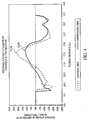
- Figure 4 illustrates the sidewall surface strain graph comparing the predicted surface strain values of the Control Tire with the predicted surface strain values of the Reinforced Tire.
- the x-axis represents the radial distance in inches from the axis of rotation of the tires, while the y-axis represents the surface strain at the center of the footprint of the tires. In this case, since both tires have a diameter of 18 inches, surface strain measurements were taken at a radial distance beginning at 9 inches and ending at about 13.5 inches (which is the end of the sidewall of the tires).
- the predicted maximum sidewall surface strain of the Control Tire was 21.8%
- the predicted maximum sidewall surface strain of the Reinforced Tire was 12%. This represents a reduction in sidewall surface strain of about 9.8%.
Landscapes
- Engineering & Computer Science (AREA)
- Mechanical Engineering (AREA)
- Tires In General (AREA)
Claims (14)
- Reifen (100), der eine Querschnittshöhe (Ho), eine maximale Querschnittsbreite (Wm), einen oberen Bereich (U) oberhalb der maximalen Querschnittsbreite (Wm) und einen unteren Bereich (L) unterhalb der maximalen Querschnittsbreite (Wm) aufweist, der Reifen (100) umfassend:ein umlaufendes Profil (102);ein Paar Seitenwände (104);ein Paar Wulstbereiche (106), wobei jeder Wulstbereich (106) einen Wulstkern (108) und einen Kernreiter (110) umfasst, der obere Wände aufweist, die an einem Apex in einer radial außenliegenden Position zusammenlaufen;mindestens eine Karkassenlage (114), die sich umlaufend um den Reifen (100) von einem Wulstbereich zum anderen erstreckt; undmindestens zwei Verstärkungslagen, wobei die mindestens zwei Verstärkungslagen eine erste und eine zweite Verstärkungslage (202, 204) umfassen, die sich um den Reifen (100) herum erstrecken, wobei die erste und die zweite Verstärkungslage (202, 204) zwischen der mindestens einen Karkassenlage (114) und mindestens einer der Seitenwände (104) des Reifens (100) vorgesehen sind, wobei die unteren Enden (208, 212) der ersten und zweiten Verstärkungslage (202, 204) im unteren Bereich (L) des Reifens (100) und die oberen Enden (206, 210) der ersten und zweiten Verstärkungslage (202, 204) im oberen Bereich (U) des Reifens (100) enden,dadurch gekennzeichnet, dassjeder Wulstbereich (106) einen Kernreitereinsatz (214) umfasst, der als Polster zwischen den Verstärkungslagen (202, 204) und der Karkassenlage (114) dient, undder Kernreitereinsatz (214) als eine vom Kernreiter (110) getrennte Komponente gefertigt ist.
- Reifen nach Anspruch 1, wobei die erste Verstärkungslage (202) einen ersten Satz parallel ausgerichteter Korde (302) und die zweite Verstärkungslage (204) einen zweiten Satz parallel ausgerichteter Korde (304) umfasst.
- Reifen nach Anspruch 2, wobei die Winkelausrichtung des ersten und des zweiten Satzes parallel ausgerichteter Korde (302, 304) zwischen ca. 45 Grad und 85 Grad zu einer Umlaufrichtung (C) des Reifens (100) beträgt.
- Reifen nach Anspruch 3, wobei der erste und der zweite Satz paralleler Korde (302, 304) quer zueinander ausgerichtet sind.
- Reifen nach Anspruch 1, wobei die mindestens eine Karkassenlage (114) nach außen um einen der Wulstkerne (108) gewickelt ist und sich in Richtung des Profils (102) erstreckt, um einen Umschlagbereich (120) zu bilden, der an einem Umschlagende (124) endet, wobei sich die unteren Enden (208, 212) der ersten und zweiten Verstärkungslage (202, 204) unterhalb des Umschlagendes (124) der mindestens einen Karkassenlage (114) erstrecken.
- Reifen nach Anspruch 5, wobei der Umschlagbereich (120) eine Höhe (H1) aufweist, die zwischen ca. 30 % und ca. 70 % der Querschnittshöhe (Ho) des Reifens (100) beträgt.
- Reifen nach Anspruch 5, wobei sich mindestens eines der unteren Enden (208, 212) der ersten und zweiten Verstärkungslage (202, 204) unterhalb des Umschlagendes (124) der mindestens einen Karkassenlage (114) in einem radialen Abstand zwischen ca. 4 mm und ca. 15 mm erstreckt.
- Reifen nach Anspruch 5, wobei die unteren Enden (208, 212) der ersten und zweiten Verstärkungslage (202, 204) zwischen der mindestens einen Karkassenlage (114) und dem Umschlagbereich (120) der mindestens einen Karkassenlage (114) vorgesehen sind.
- Reifen nach Anspruch 1, wobei der Kernreitereinsatz (214) oberhalb des Kernreiters (110) und zwischen der ersten und zweiten Verstärkungslage (202, 204) und der mindestens einen Karkassenlage (114) vorgesehen ist.
- Reifen nach Anspruch 9, wobei sich die unteren Enden (208, 212) der ersten und zweiten Verstärkungslage (202, 204) unter eines der oberen Enden (216) des Kernreitereinsatzes (214) erstrecken.
- Reifen nach Anspruch 1, der weiterhin mindestens einen Gürtel (126) umfasst, der sich um den Reifen (100) herum erstreckt, wobei der mindestens eine Gürtel (126) zwischen dem Profil (102) und der mindestens einen Karkassenlage (114) vorgesehen ist.
- Reifen nach Anspruch 11, der weiterhin einen Gürtelkanteneinsatz (136) umfasst, der zwischen einer Kante (130) des mindestens einen Gürtels (126) und der mindestens einen Karkassenlage (114) vorgesehen ist.
- Reifen nach Anspruch 12, wobei sich die oberen Enden (206, 210) der ersten und zweiten Verstärkungslage (202, 204) nach innen über ein äußeres Ende (140) des Gürtelkanteneinsatzes (136) hinaus erstrecken.
- Reifen nach Anspruch 1, wobei mindestens eines der oberen Enden (206, 210) der ersten und zweiten Verstärkungslage (202, 204) in einem Schulterbereich (134) des Reifens (100) endet.
Applications Claiming Priority (2)
| Application Number | Priority Date | Filing Date | Title |
|---|---|---|---|
| US11/217,167 US7836929B2 (en) | 2005-09-01 | 2005-09-01 | Tire having a sidewall reinforcement |
| PCT/US2006/031783 WO2007030286A1 (en) | 2005-09-01 | 2006-08-15 | Tire having a sidewall reinforcement |
Publications (2)
| Publication Number | Publication Date |
|---|---|
| EP1919720A1 EP1919720A1 (de) | 2008-05-14 |
| EP1919720B1 true EP1919720B1 (de) | 2016-03-09 |
Family
ID=37527840
Family Applications (1)
| Application Number | Title | Priority Date | Filing Date |
|---|---|---|---|
| EP06813450.1A Expired - Fee Related EP1919720B1 (de) | 2005-09-01 | 2006-08-15 | Reifen mit verstärkter seitenwand |
Country Status (5)
| Country | Link |
|---|---|
| US (1) | US7836929B2 (de) |
| EP (1) | EP1919720B1 (de) |
| JP (1) | JP5017270B2 (de) |
| CN (1) | CN100577452C (de) |
| WO (1) | WO2007030286A1 (de) |
Families Citing this family (5)
| Publication number | Priority date | Publication date | Assignee | Title |
|---|---|---|---|---|
| JP5078629B2 (ja) * | 2008-01-11 | 2012-11-21 | 株式会社ブリヂストン | 重荷重用ラジアルタイヤ |
| US8672009B2 (en) * | 2008-09-23 | 2014-03-18 | The Goodyear Tire & Rubber Company | Pneumatic tire with dual layer sidewall |
| US9073389B2 (en) | 2011-10-21 | 2015-07-07 | Bridgestone Americas Tire Operations, Llc | All steel fabric radial construction for agricultural tires |
| CN103660798B (zh) * | 2013-12-18 | 2016-09-21 | 李双龙 | 一种具有胎体加强层的全钢丝子午线轮胎 |
| CN108297622A (zh) * | 2018-03-16 | 2018-07-20 | 中国化工集团曙光橡胶工业研究设计院有限公司 | 一种加强型直升机轮胎 |
Citations (1)
| Publication number | Priority date | Publication date | Assignee | Title |
|---|---|---|---|---|
| EP1769947A1 (de) * | 2004-06-30 | 2007-04-04 | Bridgestone Corporation | Luftreifen |
Family Cites Families (96)
| Publication number | Priority date | Publication date | Assignee | Title |
|---|---|---|---|---|
| FR1490674A (fr) * | 1966-06-21 | 1967-08-04 | Michelin & Cie | Perfectionnements aux enveloppes de pneumatiques |
| NL133000C (de) * | 1966-06-28 | |||
| FR1522420A (fr) * | 1967-03-14 | 1968-04-26 | Uniroyal Englebert France | Perfectionnement aux carcasses radiales pour enveloppes de pneumatiques |
| FR1538478A (fr) * | 1967-07-24 | 1968-09-06 | Uniroyal Englebert France | Enveloppe de pneumatique à carcasse radiale à flancs renforcés |
| US3703203A (en) * | 1970-06-12 | 1972-11-21 | Goodyear Tire & Rubber | Radial wire tire having improved sidewall cut resistance |
| NL7201568A (de) * | 1971-03-17 | 1972-09-19 | ||
| BE794658A (fr) * | 1972-02-03 | 1973-07-30 | Michelin & Cie | Perfectionnements aux enveloppes de pneumatiques |
| US3904463A (en) * | 1972-02-03 | 1975-09-09 | Michelin & Cie | Radial tire with additional sidewall reinforcement |
| FR2215331B1 (de) * | 1973-01-29 | 1976-05-14 | Kleber Colombes | |
| FR2219849B1 (de) * | 1973-03-02 | 1978-03-10 | Michelin & Cie | |
| US4186789A (en) * | 1974-07-25 | 1980-02-05 | Compagnie Generale Des Etablissements Michelin | Heavy-duty radial tire with ply of oblique elastic cords radially inward of the carcass |
| IT1042802B (it) * | 1975-09-24 | 1980-01-30 | Pirelli | Perfezionamento at pneumatici radiali provvisti di struttuta di tappigio imento nei eianchi |
| JPS52116504A (en) | 1976-03-26 | 1977-09-30 | Bridgestone Corp | Pneumatic tire having superior side endurability against breakage with coil filament as reinforcing element for wild ground |
| IT1059291B (it) * | 1976-04-06 | 1982-05-31 | Pirelli | Perfezionamento ai pneumatici ra iali provvisti di struttura di irrigidimento dei fianchi |
| JPS53138106A (en) * | 1976-10-02 | 1978-12-02 | Toyo Tire & Rubber Co Ltd | Pneumatic safety tire |
| IT1073355B (it) * | 1976-10-19 | 1985-04-17 | Sarda Off Mecc Spa | Perfezionamenti alla struttura di pneumatici radiali |
| US5164029A (en) * | 1976-11-22 | 1992-11-17 | Sumitomo Rubber Industries, Ltd. | Radial tire for high load with excellent vibration damping performance |
| JPH0723284Y2 (ja) * | 1986-04-09 | 1995-05-31 | 住友ゴム工業株式会社 | ラジアルタイヤ |
| IT1075633B (it) * | 1977-04-07 | 1985-04-22 | Pirelli | Perfezionamento ai pneumatici radiali provvisti di struttura di rinforzo nei fianchi |
| US4185675A (en) * | 1978-02-22 | 1980-01-29 | Pneumatiques, Caoutchouc Manufacture Et Plastiques Kleber-Colombes | Vehicle tires |
| IT1112231B (it) * | 1979-04-10 | 1986-01-13 | Pirelli | Perfezionamento ai pneumatici radiali provvisti di struttura di irrigidimento nei fianchi |
| JPS576606U (de) * | 1980-06-13 | 1982-01-13 | ||
| JPS5893605A (ja) | 1981-11-30 | 1983-06-03 | Yokohama Rubber Co Ltd:The | ラジアルタイヤ |
| JPS59145607A (ja) | 1983-02-08 | 1984-08-21 | Sumitomo Rubber Ind Ltd | 空気入りタイヤ |
| JPS59179410A (ja) * | 1983-03-30 | 1984-10-12 | Yokohama Rubber Co Ltd:The | 二輪自動車用空気入りラジアルタイヤ |
| JPS59206206A (ja) * | 1983-05-11 | 1984-11-22 | Yokohama Rubber Co Ltd:The | 乗用車用空気入りタイヤ |
| JPS6038212A (ja) * | 1983-08-11 | 1985-02-27 | Sumitomo Rubber Ind Ltd | 自動二輪車用タイヤ |
| AU561964B2 (en) * | 1984-11-16 | 1987-05-21 | Bridgestone Corporation | Bead chafer construction |
| JPS624613A (ja) * | 1985-06-28 | 1987-01-10 | Yokohama Rubber Co Ltd:The | 空気入りタイヤ |
| EP0301093B1 (de) | 1986-04-09 | 1991-10-23 | Sumitomo Rubber Industries Limited | Radialreifen für hohe belastung mit verbesserter vibrationsdämpfung |
| JPS63203403A (ja) * | 1987-02-17 | 1988-08-23 | Sumitomo Rubber Ind Ltd | 高荷重用ラジアルタイヤ |
| FR2632252B1 (fr) | 1988-04-28 | 1994-09-16 | Bridgestone Corp | Pneumatique radial renforce a haute pression interne |
| US4854362A (en) * | 1988-05-23 | 1989-08-08 | The Goodyear Tire & Rubber Company | Pneumatic tire |
| JPH0268207A (ja) * | 1988-09-01 | 1990-03-07 | Sumitomo Rubber Ind Ltd | 重荷重高速ラジアルタイヤ |
| JPH02310110A (ja) | 1989-05-26 | 1990-12-25 | Toyo Tire & Rubber Co Ltd | ラジアルタイヤ |
| JPH03227705A (ja) * | 1990-02-01 | 1991-10-08 | Sumitomo Rubber Ind Ltd | 高荷重用ラジアルタイヤ |
| JPH04163209A (ja) | 1990-10-25 | 1992-06-08 | Sumitomo Rubber Ind Ltd | 空気入りタイヤ |
| JP2870703B2 (ja) * | 1990-11-28 | 1999-03-17 | 住友ゴム工業 株式会社 | 空気入りタイヤ |
| JP3091480B2 (ja) * | 1990-11-30 | 2000-09-25 | 住友ゴム工業株式会社 | 空気入りラジアルタイヤ |
| JPH0542803A (ja) * | 1991-08-09 | 1993-02-23 | Sumitomo Rubber Ind Ltd | 空気入りタイヤ |
| US5280817A (en) * | 1991-10-07 | 1994-01-25 | The Goodyear Tire & Rubber Company | Radial pneumatic tire having contoured zones in the sidewalls |
| US5479977A (en) | 1992-10-30 | 1996-01-02 | Sumitomo Rubber Industries, Ltd. | Pneumatic tire with carcass structure for increased sidewall rigidity |
| US5323829A (en) * | 1992-12-28 | 1994-06-28 | The Goodyear Tire & Rubber Company | Tire with carbon fiber reinforcement |
| US5261474A (en) * | 1992-12-31 | 1993-11-16 | The Goodyear Tire & Rubber Company | Earthmover tire |
| US5392830A (en) * | 1993-03-10 | 1995-02-28 | General Tire, Inc. | Protective barrier for tire sidewall |
| CA2108328A1 (en) * | 1993-06-29 | 1994-12-30 | Keith Carl Trares | High ending, locked tie-in construction |
| US5429168A (en) * | 1993-11-16 | 1995-07-04 | The Goodyear Tire & Rubber Company | Off-the-road pneumatic tire with specified bead area design |
| JP2719525B2 (ja) * | 1993-12-28 | 1998-02-25 | 住友ゴム工業株式会社 | 空気入りラジアルタイヤ |
| US5509455A (en) * | 1994-04-12 | 1996-04-23 | The Goodyear Tire & Rubber Company | Aircraft tire including reinforcement inserts |
| JP3393520B2 (ja) * | 1994-06-10 | 2003-04-07 | 住友ゴム工業株式会社 | 空気入りラジアルタイヤの製造方法 |
| US5538063A (en) * | 1994-12-23 | 1996-07-23 | The Goodyear Tire & Rubber Company | Aircraft tire with reinforcement insert |
| JP3005173B2 (ja) * | 1995-03-07 | 2000-01-31 | 住友ゴム工業株式会社 | 重荷重車用ラジアルタイヤ |
| JP3061353B2 (ja) | 1995-05-12 | 2000-07-10 | 住友ゴム工業株式会社 | 空気入りタイヤ |
| JPH09150611A (ja) * | 1995-11-30 | 1997-06-10 | Sumitomo Rubber Ind Ltd | 空気入りタイヤ |
| FR2755904A1 (fr) * | 1996-11-21 | 1998-05-22 | Michelin & Cie | Renforcement de carcasse pour pneumatique, realise a partir d'un fil unique |
| US6026878A (en) * | 1997-05-29 | 2000-02-22 | The Goodyear Tire & Rubber Company | Inextensible high temperature resistant tire |
| CN1086649C (zh) * | 1997-05-29 | 2002-06-26 | 固特异轮胎和橡胶公司 | 具有复合帘布层结构的轮胎及其制造方法 |
| US5871600A (en) * | 1997-05-29 | 1999-02-16 | The Goodyear Tire & Rubber Company | Runflat tire with different modulus or elongation carcass cords |
| US5871602A (en) * | 1997-05-29 | 1999-02-16 | The Goodyear Tire & Rubber Company | Tire with carcass turn up ends under belt structure |
| US5908685A (en) * | 1997-05-29 | 1999-06-01 | The Goodyear Tire & Rubber Company | Elastomeric composite structure |
| DE19722521A1 (de) | 1997-05-30 | 1998-12-03 | Continental Ag | Fahrzeugluftreifen |
| DE69826572T2 (de) * | 1997-07-11 | 2006-02-23 | Sumitomo Rubber Industries Ltd., Kobe | Luftreifen |
| GB9714609D0 (en) | 1997-07-12 | 1997-09-17 | Sumitomo Rubber Ind | Improvements to tyres |
| JP3782875B2 (ja) * | 1997-09-30 | 2006-06-07 | 横浜ゴム株式会社 | 空気入りラジアルタイヤ |
| GB9724053D0 (en) * | 1997-11-15 | 1998-01-14 | Sumitomo Rubber Ind | Improved pneumatic tyre constructuon and manufacturing method |
| US6142205A (en) * | 1998-03-13 | 2000-11-07 | The Goodyear Tire & Rubber Company | Tire with composite ply structure |
| US6068721A (en) * | 1998-03-27 | 2000-05-30 | The Goodyear Tire & Rubber Company | Method of fabricating a tire having a geodesic ply |
| US6358346B1 (en) * | 2000-07-28 | 2002-03-19 | The Goodyear Tire & Rubber Company | Method of building tire with composite ply structure |
| JP2000015717A (ja) * | 1998-06-30 | 2000-01-18 | Bridgestone Corp | 空気入りタイヤ用補強層の製造方法および製造設備 |
| US6527025B1 (en) * | 1998-09-11 | 2003-03-04 | Sumitomo Rubber Industries, Ltd. | Tubeless tire |
| DE19845724A1 (de) * | 1998-10-05 | 2000-04-06 | Dunlop Gmbh | Fahrzeugluftreifen |
| JP4327923B2 (ja) * | 1998-10-08 | 2009-09-09 | 株式会社ブリヂストン | 空気入りラジアルタイヤ |
| DE19846854A1 (de) * | 1998-10-12 | 2000-04-20 | Dunlop Gmbh | Fahrzeugluftreifen |
| JP2000142040A (ja) * | 1998-11-10 | 2000-05-23 | Yokohama Rubber Co Ltd:The | 空気入りタイヤ |
| JP4390932B2 (ja) | 1998-11-19 | 2009-12-24 | 株式会社ブリヂストン | 空気入りタイヤ |
| DE19860362A1 (de) * | 1998-12-24 | 2000-06-29 | Dunlop Gmbh | Fahrzeugluftreifen |
| US6763866B1 (en) * | 1999-02-03 | 2004-07-20 | The Goodyear Tire & Rubber Company | Reinforced wedge-insert construction for extended mobility tires |
| FR2789941B1 (fr) * | 1999-02-19 | 2001-04-06 | Michelin Soc Tech | Nappe de renforcement pour pneumatique, son procede de fabrication et procede de fabrication du pneumatique |
| JP2001032029A (ja) * | 1999-05-20 | 2001-02-06 | Kobe Steel Ltd | 耐応力緩和特性に優れた銅合金及びその製造方法 |
| JP3540966B2 (ja) | 1999-09-07 | 2004-07-07 | 住友ゴム工業株式会社 | 空気入りラジアルタイヤ |
| JP2001071715A (ja) | 1999-09-09 | 2001-03-21 | Bridgestone Corp | 空気入りタイヤ |
| JP4825341B2 (ja) | 1999-10-26 | 2011-11-30 | 株式会社ブリヂストン | 建設車輌用空気入りタイヤ |
| GB2361680B (en) * | 2000-04-28 | 2002-08-28 | Goodyear Tire & Rubber | A radial ply tire having a sidewall reinforcement |
| JP2002103914A (ja) * | 2000-07-25 | 2002-04-09 | Bridgestone Corp | 空気入りラジアルタイヤ |
| FR2812240A1 (fr) * | 2000-07-31 | 2002-02-01 | Michelin Soc Tech | Pneumatique avec des flancs de structure amelioree |
| JP2002079813A (ja) * | 2000-09-08 | 2002-03-19 | Sumitomo Rubber Ind Ltd | ランフラットタイヤ |
| JP4831868B2 (ja) | 2001-01-11 | 2011-12-07 | 東洋ゴム工業株式会社 | 空気入りタイヤ |
| DE60228566D1 (de) * | 2001-05-29 | 2008-10-09 | Sumitomo Rubber Ind | Druckluftreifen und verfahren zur herstellung des reifens |
| EP1397262B1 (de) * | 2001-05-31 | 2013-03-06 | Compagnie Generale Des Etablissements Michelin | Verstärkung von einer radialluftreifenseitenwand |
| JP2003205702A (ja) * | 2001-11-09 | 2003-07-22 | Bridgestone Corp | 空気入りタイヤ、空気入りタイヤ用リムホイール、及びタイヤ・リム組立体 |
| CN2558539Y (zh) | 2002-05-10 | 2003-07-02 | 袁仲雪 | 全钢丝载重子午线轮胎的子口部位加强型结构 |
| US20040007303A1 (en) * | 2002-07-10 | 2004-01-15 | Jordan Fishman | Tire with enhanced sidewall |
| US6938659B2 (en) * | 2002-09-19 | 2005-09-06 | The Goodyear Tire & Rubber Company | Runflat tire having crown-reinforcing insert extending into the sidewalls |
| US20050133135A1 (en) * | 2003-12-18 | 2005-06-23 | Corvasce Filomeno G. | Tire with sidewall having at least one internal rubber insert having graduated physical properties comprised of overlapping rubber segments |
| WO2005113260A1 (en) | 2004-04-22 | 2005-12-01 | The Goodyear Tire & Rubber Company | Pneumatic run-flat tire |
| EP1700718A3 (de) | 2005-03-10 | 2012-05-02 | Sumitomo Rubber Industries, Ltd. | Notlaufreifen |
-
2005
- 2005-09-01 US US11/217,167 patent/US7836929B2/en active Active
-
2006
- 2006-08-15 WO PCT/US2006/031783 patent/WO2007030286A1/en active Application Filing
- 2006-08-15 CN CN200680031915A patent/CN100577452C/zh not_active Expired - Fee Related
- 2006-08-15 EP EP06813450.1A patent/EP1919720B1/de not_active Expired - Fee Related
- 2006-08-15 JP JP2008529092A patent/JP5017270B2/ja not_active Expired - Fee Related
Patent Citations (1)
| Publication number | Priority date | Publication date | Assignee | Title |
|---|---|---|---|---|
| EP1769947A1 (de) * | 2004-06-30 | 2007-04-04 | Bridgestone Corporation | Luftreifen |
Also Published As
| Publication number | Publication date |
|---|---|
| CN101253060A (zh) | 2008-08-27 |
| US7836929B2 (en) | 2010-11-23 |
| CN100577452C (zh) | 2010-01-06 |
| EP1919720A1 (de) | 2008-05-14 |
| US20070044888A1 (en) | 2007-03-01 |
| JP5017270B2 (ja) | 2012-09-05 |
| WO2007030286A1 (en) | 2007-03-15 |
| JP2009506935A (ja) | 2009-02-19 |
Similar Documents
| Publication | Publication Date | Title |
|---|---|---|
| EP0678404B1 (de) | Reifen mit reduziertem Wulstgewicht | |
| EP2743098B1 (de) | Luftreifen | |
| CN108473004B (zh) | 充气轮胎 | |
| EP1928672B1 (de) | Reifen mit verstärktem wulst/verstärkter seitenwandausführung | |
| EP1197354B1 (de) | Luftreifen | |
| EP1919720B1 (de) | Reifen mit verstärkter seitenwand | |
| US20010050129A1 (en) | Pneumatic tire | |
| EP2768682B1 (de) | Radialkonstruktion aus vollstahlfasern für landwirtschaftliche reifen | |
| EP1145874B1 (de) | Flipperreifenstruktur für Notlaufreifen | |
| EP1928673B1 (de) | Reifen mit seitenwandverstärkung | |
| EP1502771A1 (de) | Luftreifen mit verbesserter Haltbarkeit der Wülste | |
| JPH06156022A (ja) | 空気入りラジアルタイヤ | |
| US8118073B2 (en) | Tire having a carcass ply turn-up portion with a concave segment | |
| US20100024960A1 (en) | Body ply and insert assembly method | |
| US5733395A (en) | Pneumatic tire for two-wheeled vehicle with hard rubber layer outside carcass turn-up | |
| EP1488939B1 (de) | Luftreifen | |
| JP3973414B2 (ja) | 空気入りラジアルタイヤ | |
| JP3377453B2 (ja) | 重荷重用タイヤ | |
| EP3189988B1 (de) | Luftreifen | |
| JPH10211806A (ja) | 重荷重用空気入りラジアルタイヤ |
Legal Events
| Date | Code | Title | Description |
|---|---|---|---|
| PUAI | Public reference made under article 153(3) epc to a published international application that has entered the european phase |
Free format text: ORIGINAL CODE: 0009012 |
|
| 17P | Request for examination filed |
Effective date: 20080212 |
|
| AK | Designated contracting states |
Kind code of ref document: A1 Designated state(s): DE ES FR GB IT |
|
| DAX | Request for extension of the european patent (deleted) | ||
| RBV | Designated contracting states (corrected) |
Designated state(s): DE ES FR GB IT |
|
| RAP1 | Party data changed (applicant data changed or rights of an application transferred) |
Owner name: BRIDGESTONE AMERICAS TIRE OPERATIONS, LLC |
|
| 17Q | First examination report despatched |
Effective date: 20131213 |
|
| RIC1 | Information provided on ipc code assigned before grant |
Ipc: B60C 9/09 20060101ALI20150629BHEP Ipc: B60C 15/06 20060101ALI20150629BHEP Ipc: B60C 17/00 20060101AFI20150629BHEP |
|
| GRAP | Despatch of communication of intention to grant a patent |
Free format text: ORIGINAL CODE: EPIDOSNIGR1 |
|
| INTG | Intention to grant announced |
Effective date: 20150818 |
|
| GRAS | Grant fee paid |
Free format text: ORIGINAL CODE: EPIDOSNIGR3 |
|
| GRAA | (expected) grant |
Free format text: ORIGINAL CODE: 0009210 |
|
| AK | Designated contracting states |
Kind code of ref document: B1 Designated state(s): DE ES FR GB IT |
|
| REG | Reference to a national code |
Ref country code: GB Ref legal event code: FG4D |
|
| REG | Reference to a national code |
Ref country code: DE Ref legal event code: R096 Ref document number: 602006048188 Country of ref document: DE |
|
| REG | Reference to a national code |
Ref country code: FR Ref legal event code: PLFP Year of fee payment: 11 |
|
| PG25 | Lapsed in a contracting state [announced via postgrant information from national office to epo] |
Ref country code: ES Free format text: LAPSE BECAUSE OF FAILURE TO SUBMIT A TRANSLATION OF THE DESCRIPTION OR TO PAY THE FEE WITHIN THE PRESCRIBED TIME-LIMIT Effective date: 20160309 |
|
| PGFP | Annual fee paid to national office [announced via postgrant information from national office to epo] |
Ref country code: IT Payment date: 20160812 Year of fee payment: 11 |
|
| PGFP | Annual fee paid to national office [announced via postgrant information from national office to epo] |
Ref country code: FR Payment date: 20160719 Year of fee payment: 11 |
|
| REG | Reference to a national code |
Ref country code: DE Ref legal event code: R097 Ref document number: 602006048188 Country of ref document: DE |
|
| PLBE | No opposition filed within time limit |
Free format text: ORIGINAL CODE: 0009261 |
|
| STAA | Information on the status of an ep patent application or granted ep patent |
Free format text: STATUS: NO OPPOSITION FILED WITHIN TIME LIMIT |
|
| 26N | No opposition filed |
Effective date: 20161212 |
|
| GBPC | Gb: european patent ceased through non-payment of renewal fee |
Effective date: 20160815 |
|
| PG25 | Lapsed in a contracting state [announced via postgrant information from national office to epo] |
Ref country code: GB Free format text: LAPSE BECAUSE OF NON-PAYMENT OF DUE FEES Effective date: 20160815 |
|
| PGFP | Annual fee paid to national office [announced via postgrant information from national office to epo] |
Ref country code: DE Payment date: 20170825 Year of fee payment: 12 |
|
| REG | Reference to a national code |
Ref country code: FR Ref legal event code: ST Effective date: 20180430 |
|
| PG25 | Lapsed in a contracting state [announced via postgrant information from national office to epo] |
Ref country code: IT Free format text: LAPSE BECAUSE OF NON-PAYMENT OF DUE FEES Effective date: 20170815 Ref country code: FR Free format text: LAPSE BECAUSE OF NON-PAYMENT OF DUE FEES Effective date: 20170831 |
|
| REG | Reference to a national code |
Ref country code: DE Ref legal event code: R119 Ref document number: 602006048188 Country of ref document: DE |
|
| PG25 | Lapsed in a contracting state [announced via postgrant information from national office to epo] |
Ref country code: DE Free format text: LAPSE BECAUSE OF NON-PAYMENT OF DUE FEES Effective date: 20190301 |