EP1908543B1 - Radius end mill and cutting method - Google Patents
Radius end mill and cutting method Download PDFInfo
- Publication number
- EP1908543B1 EP1908543B1 EP06781577.9A EP06781577A EP1908543B1 EP 1908543 B1 EP1908543 B1 EP 1908543B1 EP 06781577 A EP06781577 A EP 06781577A EP 1908543 B1 EP1908543 B1 EP 1908543B1
- Authority
- EP
- European Patent Office
- Prior art keywords
- cutting edge
- end mill
- mill body
- corner
- radius
- Prior art date
- Legal status (The legal status is an assumption and is not a legal conclusion. Google has not performed a legal analysis and makes no representation as to the accuracy of the status listed.)
- Active
Links
- 238000000034 method Methods 0.000 title claims description 11
- 230000002093 peripheral effect Effects 0.000 claims description 62
- 238000013459 approach Methods 0.000 claims description 19
- 239000000463 material Substances 0.000 description 61
- 230000007774 longterm Effects 0.000 description 7
- 230000000903 blocking effect Effects 0.000 description 2
- 229910010037 TiAlN Inorganic materials 0.000 description 1
- ATJFFYVFTNAWJD-UHFFFAOYSA-N Tin Chemical compound [Sn] ATJFFYVFTNAWJD-UHFFFAOYSA-N 0.000 description 1
- 239000000956 alloy Substances 0.000 description 1
- 229910045601 alloy Inorganic materials 0.000 description 1
- 238000007599 discharging Methods 0.000 description 1
- 230000000694 effects Effects 0.000 description 1
- 238000004519 manufacturing process Methods 0.000 description 1
- 238000009751 slip forming Methods 0.000 description 1
- 239000007787 solid Substances 0.000 description 1
- 239000011343 solid material Substances 0.000 description 1
Images

Classifications
-
- B—PERFORMING OPERATIONS; TRANSPORTING
- B23—MACHINE TOOLS; METAL-WORKING NOT OTHERWISE PROVIDED FOR
- B23C—MILLING
- B23C5/00—Milling-cutters
-
- B—PERFORMING OPERATIONS; TRANSPORTING
- B23—MACHINE TOOLS; METAL-WORKING NOT OTHERWISE PROVIDED FOR
- B23C—MILLING
- B23C5/00—Milling-cutters
- B23C5/02—Milling-cutters characterised by the shape of the cutter
- B23C5/10—Shank-type cutters, i.e. with an integral shaft
-
- B—PERFORMING OPERATIONS; TRANSPORTING
- B23—MACHINE TOOLS; METAL-WORKING NOT OTHERWISE PROVIDED FOR
- B23C—MILLING
- B23C2210/00—Details of milling cutters
- B23C2210/04—Angles
- B23C2210/0407—Cutting angles
-
- B—PERFORMING OPERATIONS; TRANSPORTING
- B23—MACHINE TOOLS; METAL-WORKING NOT OTHERWISE PROVIDED FOR
- B23C—MILLING
- B23C2210/00—Details of milling cutters
- B23C2210/12—Cross section of the cutting edge
- B23C2210/126—Rounded cutting edges
-
- B—PERFORMING OPERATIONS; TRANSPORTING
- B23—MACHINE TOOLS; METAL-WORKING NOT OTHERWISE PROVIDED FOR
- B23C—MILLING
- B23C2210/00—Details of milling cutters
- B23C2210/54—Configuration of the cutting part
-
- Y—GENERAL TAGGING OF NEW TECHNOLOGICAL DEVELOPMENTS; GENERAL TAGGING OF CROSS-SECTIONAL TECHNOLOGIES SPANNING OVER SEVERAL SECTIONS OF THE IPC; TECHNICAL SUBJECTS COVERED BY FORMER USPC CROSS-REFERENCE ART COLLECTIONS [XRACs] AND DIGESTS
- Y10—TECHNICAL SUBJECTS COVERED BY FORMER USPC
- Y10T—TECHNICAL SUBJECTS COVERED BY FORMER US CLASSIFICATION
- Y10T407/00—Cutters, for shaping
- Y10T407/19—Rotary cutting tool
- Y10T407/1946—Face or end mill
- Y10T407/1948—Face or end mill with cutting edge entirely across end of tool [e.g., router bit, end mill, etc.]
-
- Y—GENERAL TAGGING OF NEW TECHNOLOGICAL DEVELOPMENTS; GENERAL TAGGING OF CROSS-SECTIONAL TECHNOLOGIES SPANNING OVER SEVERAL SECTIONS OF THE IPC; TECHNICAL SUBJECTS COVERED BY FORMER USPC CROSS-REFERENCE ART COLLECTIONS [XRACs] AND DIGESTS
- Y10—TECHNICAL SUBJECTS COVERED BY FORMER USPC
- Y10T—TECHNICAL SUBJECTS COVERED BY FORMER US CLASSIFICATION
- Y10T407/00—Cutters, for shaping
- Y10T407/19—Rotary cutting tool
- Y10T407/1952—Having peripherally spaced teeth
- Y10T407/1962—Specified tooth shape or spacing
- Y10T407/1964—Arcuate cutting edge
- Y10T407/1966—Helical tooth
-
- Y—GENERAL TAGGING OF NEW TECHNOLOGICAL DEVELOPMENTS; GENERAL TAGGING OF CROSS-SECTIONAL TECHNOLOGIES SPANNING OVER SEVERAL SECTIONS OF THE IPC; TECHNICAL SUBJECTS COVERED BY FORMER USPC CROSS-REFERENCE ART COLLECTIONS [XRACs] AND DIGESTS
- Y10—TECHNICAL SUBJECTS COVERED BY FORMER USPC
- Y10T—TECHNICAL SUBJECTS COVERED BY FORMER US CLASSIFICATION
- Y10T407/00—Cutters, for shaping
- Y10T407/23—Cutters, for shaping including tool having plural alternatively usable cutting edges
-
- Y—GENERAL TAGGING OF NEW TECHNOLOGICAL DEVELOPMENTS; GENERAL TAGGING OF CROSS-SECTIONAL TECHNOLOGIES SPANNING OVER SEVERAL SECTIONS OF THE IPC; TECHNICAL SUBJECTS COVERED BY FORMER USPC CROSS-REFERENCE ART COLLECTIONS [XRACs] AND DIGESTS
- Y10—TECHNICAL SUBJECTS COVERED BY FORMER USPC
- Y10T—TECHNICAL SUBJECTS COVERED BY FORMER US CLASSIFICATION
- Y10T409/00—Gear cutting, milling, or planing
- Y10T409/30—Milling
- Y10T409/303752—Process
Definitions
- This invention relates to a radius end mill used to cut an object to form a mold or the like, and a cutting method using the radius end mill.
- each of the chip ejection grooves is formed at a peripheral portion of an end mill body located close to a distal end of the body so as to be twisted backward in the rotation direction of the end mill as the chip ejection groove approaches the terminal end of the end mill body.
- Each of the peripheral cutting edges is formed at a wall surface of the chip ejection groove facing forward in the rotation direction of the end mill so as to be along a ridge line of the wall surface to be close to the outer circumference of the end mill body.
- Each of the bottom cutting edges is formed at the wall surface of the chip ejection groove so as to be along a ridge line of the wall surface located close to the distal end of the end mill body.
- Each of the corner cutting edges is formed between the peripheral cutting edge and the bottom cutting edge so as to communicate the peripheral cutting edge with the bottom cutting edge, and is formed like an arcuate line which curves outward in the radial direction of the end mill body and which curves toward the distal end of the end mill body from the terminal end thereof.
- the high feed-speed cutting means that the feed speed of a cutting device such as an end mill is accelerated. He high feed-speed cutting is performed, the cutting amount in the forward direction per one cutting edge is increased. Thus an outline of the cutting edge is transcribed to a surface of a material to be cut, and thereby the surface of the material becomes rough. Further, the cutting resistance acting on the cutting edge is increased, and thereby the lacking and chipping of the cutting edge may be happened. Furthermore, if the chips become large, the chips are hardly ejected from the groove easily. Therefore, the cutting resistance is increased depending upon blocking of the chips within the ejection groove, and the surface of the material to be cut is damaged by the chips.
- radius end mills for the high feed-speed cutting are disclosed in Patent Documents 1 and 2 mentioned below.
- a curvature radius of the corner cutting edge is greater than or equal to 40 % of the outer diameter of the end mill and is less than 50 % thereof.
- the radius end mill is formed so that a center area of a distal end surface thereof subsides.
- the curvature radius of the corner cutting edge of this end mill is larger than that of conventional end mill. Therefore, the outline of the cutting edge transcribed to the surface of the material to be cut becomes smooth. As a result, if the feed speed of the cutting device is increased, it is possible to make the surface of the material smooth.
- a rake surface of each corner cutting edge curves upwardly.
- a chip space recessed toward a distal end of an end mill body is formed at a part of the corner cutting edge located close to an outer circumference of the end mill body so as to communicate with the rake surface. Since the rake surface of the corner cutting edge of this end mill curves upwardly, the intensity of the corner cutting edge can be improved. Therefore, it is possible to generate lacking and chipping of the cutting edges. Accordingly, it is possible to stably-cut the material by the radius end mill. In addition, since chips can be discharged through chip base continuously formed on the rake surface, the chips separate from the rake surface immediately. Accordingly discharge of the chips can be improved. Therefore, it is possible to prevent the chips from blocking the recessed chip space.
- Document JP 2004 141 975 A discloses a radius end mill according to the preamble of claim 1.
- a pocket of which an opening is formed like a substantially multi-angle shape may be formed on the surface of the material.
- the outer circumference of the end mill contacts a side surface of the material in which the pocket is formed, thus the contact length of the cutting edge with respect to the side surface of the material is elongated.
- the contact length of the cutting edge with respect to the side surface of the material is further elongated, thus a vibration of the end mill is caused by increase of the cutting resistance. Therefore, there is a problem that the smoothness of the surface of the material to be cut deteriorates.
- the contact length of the corner cutting edge is elongated, since the curvature radius of the cutting edge is large. Thereby, the cutting resistance is increased. In particular, when the angle parts and the outline part of the pocket are cut, the contact length of the cutting edge is further elongated. Thus, the vibration of the end mill is caused by an increase of the cutting resistance. In order to prevent the end mill from vibrating, it is necessary to reduce the forward cutting speed of the end mill. Therefore, there is a problem that the cutting efficiency of the material deteriorates.
- the present invention has been conceived in order to solve the above described problem, and it is an object thereof to provide a radius end mill and a cutting method using the radius end mill.
- the radius end mill and the cutting method of the present invention enable the high feed-speed cutting at angle parts and an outline part of the pocket to efficiently cut a material.
- the radius end mill and the cutting method enable the material's surface to be made smooth.
- the radius end mill and the cutting method are inexpensively manufacturable.
- the radius end mill and the cutting method enable the cutting edges to be re-ground for long-term use.
- a radius end mill of the present invention is defined in claim 1 and includes: an end mill body which is rotatable around an axis; peripheral cutting edges each formed at a peripheral portion of the end mill body located close to a distal end thereof so as to extend from the distal end of the end mill body toward a terminal end thereof; bottom cutting edges each formed at a distal end surface of the end mill body so as to extend from the vicinity of the axis outward in the radial direction of the end mill; and corner cutting edges each formed between the peripheral cutting edge and the bottom cutting edge so as to communicate the peripheral cutting edge with the bottom cutting edge, each of the corner cutting edges being formed so as to protrude outward in the radial direction of the end mill body and so as to protrude from the terminal end of the end mill body toward the distal end thereof.
- the corner cutting edge is formed so as to curve inward in the radial direction as the corner cutting edge approaches the distal end of the end mill body from the terminal end thereof and so as to curve toward the terminal end of the end mill body after the corner cutting edge has reached the distal end of the end mill body.
- the bottom cutting edge is formed so as to communicate with the corner cutting edge and so as to be close to the terminal end of the end mill body as the bottom cutting edge approaches inward in the radial direction.
- a value of a rake angle ⁇ of the corner cutting edge with respect to the axis is greater than or equal to -10° and is less than or equal to 10°.
- a rake surface of the corner cutting edge and a rake surface of the bottom cutting edge each are formed like a plane, and the rake surface of the corner cutting edge is formed so as to be flush with the rake surface of the bottom cutting edge.
- a value of a curvature radius R of the corner cutting edge is greater than or equal to 0.1 x D and is less than or equal to 0.3 x D.
- the value of the rake angle ⁇ of the corner cutting edge with respect to the axis is greater than or equal to -10° and is less than or equal to 10°, that is, the value of the rake angle ⁇ of the corner cutting edge is substantially 0°.
- the curvature radius R of the corner cutting edge is greater than or equal to 0.1 x D and is less than or equal to 0.3 x D, that is, the curvature radius R of the corner cutting edge is larger than the diameter D of the end mill body.
- a rake surface of the corner cutting edge along the radial direction of the end mill body is also substantially 0°.
- the corner cutting edge becomes sharp, and thereby the cutting resistance is reduced.
- the corner cutting edge and the bottom cutting edge can be formed easily, it is possible to produce the radius end mill inexpensively.
- the bottom cutting edge is formed so as to communicate with the corner cutting edge and so as to be close to the terminal end of the end mill body from the distal end thereof as the bottom cutting edge approaches inward in the radial direction, in other words, the bottom cutting edge on the distal end surface of the end mill body is recessed as nearer the center of the distal end surface.
- the radius end mill of the present invention may be arranged such that the value of an angle ⁇ of the bottom cutting edge with respect to a plane being orthogonal to the axis be greater than or equal to 3° and be less than or equal to 8°.
- the contact length of the bottom cutting edge with respect to the material to be cut is short, and the contact length of the corner cutting edge with respect to the material to be cut is also short. As a result, it is possible to reduce the cutting resistance of the cutting device.
- the radius end mill of the present invention may be arranged such that the peripheral cutting edge be formed so as to be twisted backward in the rotation direction of the end mill as the peripheral cutting edge approaches the terminal end of the end mill body from the distal end thereof, and a value of a twist angle ⁇ of the peripheral cutting edge with respect to the axis be greater than or equal to 10° and be less than or equal to 30°.
- a twist angle ⁇ of the peripheral cutting edge with respect to the axis be greater than or equal to 10° and be less than or equal to 30°.
- the rake angle ⁇ may be smaller than the twist angle ⁇ .
- the rake surface of the corner cutting edge can be re-ground with maintaining the rake angle ⁇ for long-term use. As a result, it is possible to extend the life span of the end mill.
- the peripheral cutting edge is provided with a back taper so that the external diameter of the end mill body reduces as the peripheral cutting edge approaches the terminal end of the end mill body from the distal end thereof, and a value of a taper angle ⁇ of the back taper is more than 0° and is less than 1°.
- a taper angle ⁇ of the back taper is more than 0° and is less than 1°.
- clearance surfaces of the corner cutting edge and the peripheral cutting edge may be formed so that the clearance surface of the corner cutting edge communicates with the clearance surface of the peripheral cutting edge.
- a side surface of the pocket of the material to be cut can be formed smooth. As a result, it is possible to make the side surface of the pocket smooth after cutting.
- the present invention is a cutting method according to claim 5, for cutting an object using the radius end mill as described in claim 3.
- a depth of cutting in the axial direction with respect to the object is less than or equal to a curvature radius R of the corner cutting edge.
- the depth of cutting in the axial direction with respect to the object is less than or equal to the curvature radius R of the corner cutting edge.
- the present invention when the pocket or the like is formed in the material, even if a multi-angle part and an outline of a pocket are cut, it is possible to perform the high feed-speed cutting to improve the cutting efficiency of the material. Further, it is possible to cut the surface of the material to be smooth. Furthermore, it is possible to produce the radius end mill inexpensively. In addition, the radius end mill can be re-ground for long-term use.
- the radius end mill of the present invention will be explained with reference to attached figures.
- the radius end mill of the present invention is disclosed.
- angle parts and an outline part of a material to be cut is disclosed when the pocket is formed in the material using the radius end mill of this embodiment.
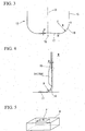
- An end mill body 11 is made of solid material such as ultrahard alloy. As shown in FIG. 1 , the end millbody 11 is formed like a cylindrical solid column center on an axis O. A part (upper part of the end mill 11 shown in FIG.1 ) of the end mill body 11 located close to a terminal end thereof is provided with a shank portion 12 which is for attaching the end mill body 11 to an end of a main shaft of a machine tool. A part (on the lower part of the end mill 11 shown in FIG.1 ) of the end mill body 11 located close to a distal end thereof is provided with cutting edge portion 13.
- the cutting edge portion 13 includes chip ejection grooves 14, peripheral cutting edges 15, bottom cutting edges 17 and corner cutting edges 18.
- the chip ejection grooves 14 are formed at the outer circumference of the cutting edge portion 13 so as to separate from each other at regular intervals in a circumferential direction of the end mill body 11 (four grooves in this embodiment).
- Each of the chip ejection groove 14 extends toward the terminal end of the end mill body 11 from the distal end thereof, and is formed at a peripheral portion of an end mill body located close to a distal end of the body so as to be twisted backward in the rotation direction T of the end mill around the axis O as the chip ejection groove 14 approaches the terminal end of the end mill body 11 from the distal end thereof.
- Each of the peripheral cutting edge 15 is formed along a ridge line at which a wall surface of the chip ejection groove 14 facing forward in the rotation direction T of the end mill contacts a peripheral surface of the cutting edge portion 13 being continuous backward in the rotation direction T of the end mill (that is, along the ridge line of the wall surface located close to the outer circumference of the end mill body 11).
- the peripheral cutting edge 15 is formed so as to be twisted backward in the rotation direction T of the end mill around the axis O as the peripheral cutting edge 15 approaches the terminal end of the end mill body 11 from the distal end thereof.
- the wall surface of the chip ejection groove 14 facing forward in the rotation direction T of the end mill is a rake surface 15A of the peripheral cutting edge 15, and a part being continuous to the peripheral cutting edge 15 among the outer circumferential surface of the cutting edge portion 13 is a clearance surface 15B.
- a value of a twist angle ⁇ of the peripheral cutting edge 15 with respect to the axis O is greater than or equal to 10° and is less than or equal to 30°.
- the value of the twist angle ⁇ is greater than or equal to 10° and is less than or equal to 20°.
- the clearance surface 15B of the peripheral cutting edge 15, that is, the outer circumferential surface of the cutting edge portion 13 is provided with a back taper so that the outer diameter of the cutting edge portion 13 is gradually reduced as the clearance surface 15B approaches the terminal end of the end mill body 11 from the distal end thereof.
- a value of a taper angle ⁇ of this back taper is more than 0° and is less than or equal to 1° (greater than or equal to 0.8° in this embodiment).
- End gashes 16 are formed at a top end of the cutting edge portion 13, that is, the distal end of the end mill body 11 (four gashes in this embodiment of FIG.2 ). Each of the end gashes 16 communicates with the chip ejection groove 14, and is recessed inwardly in the radial direction of the end mill body 11. Each of the bottom cutting edges 17 is formed on a wall surface of the end gash 16 facing forward in the rotation direction T of the end mill so as to be along a ridge line of the wall surface located close to the distal end of the end mill body 11.
- the bottom cutting edge 17 extends forward in the radial direction of the end mill body 11 from the vicinity of the axis O, that is, the center of the distal end surface of the cutting edge portion 13, and is formed linearly so as to incline toward the terminal end of the end mill body 11 from the distal end thereof as the bottom cutting edge 17 approaches inwardly in the radial direction of the end mill body 11.
- the wall surface of the end gash 16 facing forward in the rotation direction T of the end mill is as a rake surface 17A of the bottom cutting edge 17, and a part of the distal end surface of the cutting edge portion 13 being continuous to the bottom cutting edge 17 is as a clearance surface 17B of the bottom cutting edge 17.
- Each of the corner cutting edges 18 is formed between the peripheral cutting edge 15 and the bottom cutting edge 17 so as to communicate the peripheral cutting edge 15 with the bottom cutting edge 17 as seen in the rotation direction T of the end mill body 11, and is formed like an arcuate line which curves outward in the radial direction of the end mill body 11 and which curves toward the distal end of the end mill body 11 from the terminal end thereof.
- the corner cutting edge 18 is formed so as to curve by a curvature radius R around a center C.
- the center C of the curvature radius R of the corner cutting edge 18 is located closer to the distal end of the end mill body 11 than a contact point G of the peripheral cutting edge 15 and the corner cutting edge 18. That is, a length of the corner cutting edge 18 to the contact point G from the distal end of the cutting edge portion 13 along the axis O is longer than the curvature radius R.
- the center C is located more outward in the radial direction of the end mill body 11 than a contact point H of the bottom cutting edge 17 and the corner cutting edge 18. That is, the length of the corner cutting edge 18 to the contact point H to the outer circumference of the cutting edge portion 13 along the radial direction of the end mill body 11 is longer than the curvature radius R.
- the corner cutting edge 18 curves inwardly in the radial direction of the end mill body 11 as the corner cutting edge 18 approaches the distal end of the end mill body 11 from the terminal end thereof, and is curves toward the terminal end of the end mill body 11 between the contact point H and the center of the distal end surface of the end mill body 11.
- a value of the curvature radius R of the corner cutting edge 18 is greater than or equal to 0.1 x D and is less than or equal to 0.3 x D.
- a value of a rake angle ⁇ of the corner cutting edge 18 with respect to the axis is greater than or equal to -10° and is less than or equal to 10° (0° in this embodiment).
- the rake surface 18A of the corner cutting edge 18 is formed so as to be flush with the rake surface 17A of the bottom cutting edge 17 (that is, the wall surface of the end gash 16 facing forward in the rotation direction T of the end mill).
- the rake surface 18A of the corner cutting edge 18 and the rake surface 17A of the bottom cutting edge 17 each are formed like a plane, and the rake surface 18A of the corner cutting edge 18 is formed so as to be flush with the rake surface 17A of the bottom cutting edge 17. Therefore, a value of the corner cutting edge 18 with respect to the radial direction of the end mill body 11 is also substantially 0°.
- the clearance surface 18B of the corner cutting edge 18 is formed so as to communicate with the clearance surface 15B of the peripheral cutting edge 15.
- the rake surface 17A of the bottom cutting edge 17 and the rake surface 18A of the corner cutting edge 18 each extend toward the terminal end of the end mill body 11 from the distal end thereof along the axis O, and each communicate with the rake surface 15A of the peripheral cutting edge 15.
- Each rake surface 15A is formed so as to be twisted backward in the rotation direction T of the end mill as the rake surface 15A approaches the terminal end of the end mill body 11 from the distal end thereof, and each is formed so as to incline by the twist angle ⁇ with respect to the axis O.
- the clearance surface 18B of the corner cutting edge 18 is formed so as to be along the rake surface 18A, and the clearance surface 18B of the corner cutting edge 18 is formed so as to be along the rake surface 15A.
- the depth of the chip ejection groove 14 in a cross-sectional direction orthogonal to the axis O is less than or equal to 0.075 x D, and a core diameter of the end mill is greater than or equal to 0.85 x D. Therefore, in the rake surface 18A of the corner cutting edge 18 from a side view, a part of the rake surface 18A located outward in the radial direction of the end mill body 11 communicates with the wall surface of the chip ejection groove 14 facing forward in the rotation direction T of the end mill to form the rake surface 15A of the peripheral cutting edge 15.
- a recessed portion 19 is formed at the center area of the distal end surface of the cutting edge portion 13.
- the bottom cutting edge 17 communicates with the corner cutting edge 18 and inclines toward the terminal end of the end mill body 11 as the bottom cutting edge 17 approaches inward in the radial direction of the end mill body 11, and thereby the recessed portion 19 is formed.
- the value of an angle ⁇ of the bottom cutting edge 17 which forms the recessed portion 19 with respect to a plane orthogonal to the axis O is greater than or equal to 3° and is less than or equal to 8° (6° in this embodiment).
- the radius end mill as described above is attached to the end of the main shaft of the machine tool through the shank portion 12. Then, the radius end mill is fed in the direction orthogonal to the axis O along with being rotated around the axis O, and thereby the radius end mill cuts the material W so as to form a pocket or the like.
- the radius end mill is used to perform the high feed-speed cutting of which the feed speed in the direction orthogonal to the axis O is high.
- the depth of cutting in the direction of the axis O with respect to the material W is less than or equal to the curvature radius R of the corner cutting edge 18.
- the length of the corner cutting edge 18 to the contact point G from the distal end of the cutting edge portion 13 along the axis O is longer than the curvature radius R, and the peripheral cutting edge 15 is located so as to separate from the distal end of the cutting edge portion 13 toward the terminal end of the end mill body 11 more than the curvature radius R.
- the corner cutting edges 18 and the bottom cutting edges 17 are mainly used to cut, and the peripheral cutting edges 15 are not used to cut. Therefore, the contact length of the cutting edge portion 13 with respect to the material W can be shortened, and thereby the cutting resistance of the cutting device can be reduced. As a result, it is possible to prevent the radius end mill from vibrating. Accordingly, it is possible to make the surface of the material smooth.
- the value of the rake angle ⁇ of the corner cutting edge 18 with respect to the axis O is 0°, and the rake angle of the corner cutting edge 18 with respect to the radial direction of the end mill body 11 is also 0°.
- the curvature radius R of the corner cutting edge 18 is less than or equal to 0.3 x D (D is the outer diameter of the end mill). Therefore, the contact length of the corner cutting edge 18 with respect to the material W can be shortened, and thereby the cutting resistance of the cutting device can be reduced. As a result, it is possible to prevent the radius end mill from vibrating and it is possible to prevent the cutting edge portion 13 from generating lacks and chipping.
- the curvature radius R of the corner cutting edge 18 is greater than or equal to 0.1 x D.
- the rake surface 18A of the corner cutting edge 18 and the rake surface 17A of the bottom cutting edge 17 each are formed as a plane, and the rake surface 18A of the corner cutting edge 18 is formed so as to be flush with the rake surface 17A of the bottom cutting edge 17, the sharpness of the corner cutting edge 18 can be improved, and thereby the cutting resistance of the cutting device can be reduced.
- the corner cutting edge and the bottom cutting edge can be formed easily, it is possible to produce the radius end mill inexpensively.
- the value of the angle ⁇ of the bottom cutting edge 17 with respect to the plane orthogonal to the axis O is greater than or equal to 3° and is less than or equal to 8° (6° in this embodiment).
- the recessed portion 19 is formed at the center area of the distal end surface of the cutting edge portion 13.
- the peripheral cutting edge 15 is formed so as to be twisted backward in the rotation direction T of the end mill as the peripheral cutting edge 15 approaches the terminal end of the end mill body 11 from the distal end thereof, and the twist angle ⁇ of the peripheral cutting edge 15 with respect to the axis O is greater than or equal to 10° and is less than or equal to 30°.
- the clearance surface 15B of the peripheral cutting edge 15 is provided with the back taper so that the outer diameter of the cutting edge portion 13 is gradually reduced as the clearance surface 15B approaches the terminal end of the end mill body 11 from the distal end thereof.
- the value of the taper angle ⁇ of this back taper is more than 0° and is less than or equal to 1 ° (greater than or equal to 0.8° in this embodiment).
- the value of the back taper angle ⁇ is more than 0° and is less than 1 °.
- the value of the rake angle ⁇ of the corner cutting edge 18 is 0°, and is the value of the twist angle ⁇ of the peripheral cutting edge 15 is greater than or equal to 10° and is less than or equal to 30°. That is, the rake angle ⁇ is smaller than the twist angle ⁇ .
- the rake surface 18A of the corner cutting edge 18 can be re-ground with maintaining the rake angle ⁇ for long-term use. As a result, it is possible to improve the life span of the end mill.
- the clearance surface 18B of the corner cutting edge 18 is formed so as to smoothly communicate with the clearance surface 15B of the peripheral cutting edge 15.
- the depth of the chip ejection groove 14 in the cross-sectional direction orthogonal to the axis O is less than or equal to 0.075 x D, and the core diameter of the radius end mill is greater than or equal to 0.85 x D.
- the depth of the chip ejection groove 14 in the cross-sectional direction orthogonal to the axis O is less than or equal to 0.075 x D, and the core diameter of the radius end mill is greater than or equal to 0.85 x D.
- the four-edge end mill has been explained.
- the end mill is provided with four chip ejection grooves, and is provided with four peripheral cutting edges, four bottom cutting edges and four corner cutting edges.
- the radius end mill of the present invention has not limitations with regard to the number of the peripheral cutting edges, the bottom cutting edges and the corner cutting edges, and the radius end mill may be provided with five or more cutting edges, or may be provided with three or less cutting edges.
- film of hard material such as TiN and TiAlN may be coated on the surface of each of the cutting edges.
Applications Claiming Priority (2)
| Application Number | Priority Date | Filing Date | Title |
|---|---|---|---|
| JP2005214210A JP2007030074A (ja) | 2005-07-25 | 2005-07-25 | ラジアスエンドミル及び切削加工方法 |
| PCT/JP2006/314665 WO2007013447A1 (ja) | 2005-07-25 | 2006-07-25 | ラジアスエンドミルおよび切削加工方法 |
Publications (3)
| Publication Number | Publication Date |
|---|---|
| EP1908543A1 EP1908543A1 (en) | 2008-04-09 |
| EP1908543A4 EP1908543A4 (en) | 2008-08-06 |
| EP1908543B1 true EP1908543B1 (en) | 2015-04-08 |
Family
ID=37683343
Family Applications (1)
| Application Number | Title | Priority Date | Filing Date |
|---|---|---|---|
| EP06781577.9A Active EP1908543B1 (en) | 2005-07-25 | 2006-07-25 | Radius end mill and cutting method |
Country Status (6)
| Country | Link |
|---|---|
| US (1) | US7997834B2 (ko) |
| EP (1) | EP1908543B1 (ko) |
| JP (1) | JP2007030074A (ko) |
| KR (1) | KR101351727B1 (ko) |
| CN (1) | CN101247914B (ko) |
| WO (1) | WO2007013447A1 (ko) |
Cited By (1)
| Publication number | Priority date | Publication date | Assignee | Title |
|---|---|---|---|---|
| CN106844988A (zh) * | 2017-02-06 | 2017-06-13 | 成都天佑创软科技有限公司 | 生成具有齿偏中心量的立铣刀底齿平面刀刃曲线的方法 |
Families Citing this family (45)
| Publication number | Priority date | Publication date | Assignee | Title |
|---|---|---|---|---|
| WO2005058532A1 (en) * | 2003-12-17 | 2005-06-30 | Showa Denko K.K. | Method for producing forging die, forging die and forged article |
| IL174775A (en) | 2006-04-04 | 2013-06-27 | Hanita Metal Works Ltd | Milling face |
| US7431538B1 (en) * | 2007-04-12 | 2008-10-07 | Kennametal Inc. | End mill for orbital drilling of fiber reinforced plastic materials |
| JP4809283B2 (ja) * | 2007-04-23 | 2011-11-09 | ユニオンツール株式会社 | 回転切削工具 |
| FR2920327B1 (fr) * | 2007-08-30 | 2009-11-20 | Snecma | Fraise a rainurer pour usinage a grande avance et a faible profondeur de passe |
| JP5088678B2 (ja) * | 2007-08-31 | 2012-12-05 | 日立ツール株式会社 | ロングネックラジアスエンドミル |
| JP5731102B2 (ja) * | 2009-01-21 | 2015-06-10 | 三菱マテリアル株式会社 | ラジアスエンドミル |
| SE0950135A1 (sv) * | 2009-03-09 | 2010-06-08 | Seco Tools Ab | Skärverktyg med radiella skäreggar |
| CA2787116C (en) * | 2010-01-14 | 2015-08-25 | Osstemimplant Co., Ltd. | Drill for implant surgery |
| JP5302941B2 (ja) * | 2010-10-07 | 2013-10-02 | 三菱重工業株式会社 | ラフィングボールエンドミル |
| JP5302943B2 (ja) * | 2010-10-15 | 2013-10-02 | 三菱重工業株式会社 | ラジアスエンドミル |
| US8647025B2 (en) * | 2011-01-17 | 2014-02-11 | Kennametal Inc. | Monolithic ceramic end mill |
| JP5803647B2 (ja) * | 2011-02-16 | 2015-11-04 | 三菱日立ツール株式会社 | エンドミル |
| JP5016737B1 (ja) * | 2011-06-17 | 2012-09-05 | 日立ツール株式会社 | 多刃エンドミル |
| KR101746483B1 (ko) | 2011-06-17 | 2017-06-13 | 미츠비시 히타치 쓰루 가부시키가이샤 | 다날 엔드밀 |
| WO2013099954A1 (ja) * | 2011-12-27 | 2013-07-04 | 京セラ株式会社 | ラジアスエンドミル |
| CN104640658B (zh) * | 2012-07-27 | 2016-08-17 | 日立工具股份有限公司 | 多刃立铣刀 |
| JP6089596B2 (ja) * | 2012-10-31 | 2017-03-08 | 三菱マテリアル株式会社 | エンドミル及びその製造方法 |
| CN103028769A (zh) * | 2012-12-12 | 2013-04-10 | 大连瑞谷科技有限公司 | 用于奇数方形兜孔保持架成型铣刀 |
| CN104014859A (zh) * | 2013-02-28 | 2014-09-03 | 三菱综合材料株式会社 | 立铣刀及其制造方法 |
| CN104162705B (zh) * | 2013-05-20 | 2017-02-08 | 基准精密工业(惠州)有限公司 | 铣刀 |
| CN103286364A (zh) * | 2013-06-28 | 2013-09-11 | 哈尔滨理工大学 | 一种平坦曲面加工用圆弧顶铣削刀具 |
| JP6347258B2 (ja) * | 2013-11-08 | 2018-07-04 | 三菱日立ツール株式会社 | ラジアスエンドミル及び切削加工方法 |
| WO2015075117A1 (de) * | 2013-11-20 | 2015-05-28 | MAPAL Fabrik für Präzisionswerkzeuge Dr. Kress KG | Fräswerkzeug |
| US10040137B2 (en) * | 2014-01-28 | 2018-08-07 | United Technologies Corporation | Compound fillet radii cutter |
| JP5786991B2 (ja) * | 2014-03-03 | 2015-09-30 | 三菱マテリアル株式会社 | ラジアスエンドミル |
| DE102014103103A1 (de) | 2014-03-07 | 2015-09-10 | Gühring KG | Schaftfräser |
| CN104001979B (zh) * | 2014-06-19 | 2017-02-08 | 哈尔滨理工大学 | 带有锥角结构的等弧直立槽环形铣刀及磨削方法 |
| CN104096871A (zh) * | 2014-07-10 | 2014-10-15 | 无锡蠡湖叶轮制造有限公司 | 一种可防卷屑的槽刀 |
| US9517515B2 (en) * | 2014-09-15 | 2016-12-13 | Iscar, Ltd. | End mill convex radial relief surface and corner having circular arc profile |
| JP6508212B2 (ja) | 2014-10-28 | 2019-05-15 | 三菱日立ツール株式会社 | セラミックエンドミル及びそれを用いた難削材の切削方法 |
| CN104959667B (zh) * | 2015-05-12 | 2018-03-23 | 哈尔滨理工大学 | 一种偏心形后刀面带不等距圆弧头铣刀及磨削方法 |
| US10040136B2 (en) | 2015-10-12 | 2018-08-07 | Iscar, Ltd. | End mill having teeth and associated flutes with correlated physical parameters |
| IL249676B (en) | 2016-12-20 | 2021-08-31 | Hanita Metal Works Ltd | An end mill with differently rotated slot profiles |
| KR20190033092A (ko) * | 2017-02-16 | 2019-03-28 | 스미또모 가가꾸 가부시키가이샤 | 스퍼터링 타깃용 깎기 공구, 스퍼터링 타깃의 가공 방법 및 스퍼터링 타깃 제품의 제조 방법 |
| US9884379B1 (en) * | 2017-03-07 | 2018-02-06 | Iscar, Ltd. | Ceramic face mill with circular arc profile for machining Inconel |
| JP6894506B2 (ja) * | 2017-05-30 | 2021-06-30 | 京セラ株式会社 | エンドミル及び切削加工物の製造方法 |
| CN107824852A (zh) * | 2017-11-20 | 2018-03-23 | 中山市园丰精密刃具有限公司 | 一种连续角加工铣刀 |
| CN111670081B (zh) * | 2018-02-02 | 2023-06-23 | 株式会社Moldino | 立铣刀及加工方法 |
| US10486246B2 (en) | 2018-02-26 | 2019-11-26 | Iscar, Ltd. | End mill having a peripheral cutting edge with a variable angle configuration |
| JP7139266B2 (ja) * | 2019-02-22 | 2022-09-20 | 三菱重工業株式会社 | エンドミル |
| WO2022064595A1 (ja) * | 2020-09-24 | 2022-03-31 | 株式会社Moldino | エンドミル |
| CN113369551A (zh) * | 2021-06-25 | 2021-09-10 | 成都飞机工业(集团)有限责任公司 | 一种立铣刀及基于立铣刀的转轴梁翼面双曲面铣削方法 |
| US11865629B2 (en) | 2021-11-04 | 2024-01-09 | Kennametal Inc. | Rotary cutting tool with high ramp angle capability |
| JP7403610B1 (ja) | 2022-11-04 | 2023-12-22 | 日進工具株式会社 | 被覆切削工具 |
Family Cites Families (20)
| Publication number | Priority date | Publication date | Assignee | Title |
|---|---|---|---|---|
| US4300862A (en) * | 1979-09-05 | 1981-11-17 | Dijet Industrial Co., Ltd. | End milling tool |
| JPS6386921A (ja) * | 1986-09-30 | 1988-04-18 | Matsushita Electric Ind Co Ltd | 再生回路 |
| US5190420A (en) * | 1989-06-20 | 1993-03-02 | Hitachi Tool Kabushiki Kaisha | Solid end mill for finishing the face or side of hard work |
| US5226760A (en) * | 1990-02-07 | 1993-07-13 | Gn Tool Co., Ltd. | Cutting tool with twisted edge and manufacturing method thereof |
| SE9300875D0 (sv) * | 1993-03-17 | 1993-03-17 | Sandvik Ab | Pinnfraes |
| JP4372859B2 (ja) * | 1998-06-15 | 2009-11-25 | オーエスジー株式会社 | エンドミル |
| JP2001009627A (ja) * | 1999-06-25 | 2001-01-16 | Toshiba Tungaloy Co Ltd | スローアウェイ式カッタ |
| JP2002273611A (ja) * | 2001-03-21 | 2002-09-25 | Toshiba Corp | スローアウェイ式エンドミル及び切り刃チップ並びにこれらを用いた加工方法 |
| JP2002292514A (ja) | 2001-03-30 | 2002-10-08 | Hitachi Tool Engineering Ltd | 小径の等高線切削用エンドミル |
| JP2003165015A (ja) * | 2001-11-30 | 2003-06-10 | Hitachi Tool Engineering Ltd | コーナーラジラスエンドミル |
| JP3734465B2 (ja) | 2002-08-27 | 2006-01-11 | 日立ツール株式会社 | 高送り切削用ラジアスエンドミル |
| US6846135B2 (en) * | 2002-03-25 | 2005-01-25 | Hitachi Tool Engineering Ltd. | Radius end mill having radius edge enhanced in resistance to chipping and fracture |
| JP2004005338A (ja) * | 2002-03-27 | 2004-01-08 | Yunirekku:Kk | 個人認証装置、販売管理装置 |
| JP4540292B2 (ja) * | 2002-10-22 | 2010-09-08 | オーエスジー株式会社 | ラジアスエンドミル |
| JP2004209559A (ja) * | 2002-12-27 | 2004-07-29 | Sumitomo Electric Ind Ltd | バックテーパ付きエンドミル |
| JP4313579B2 (ja) * | 2003-01-22 | 2009-08-12 | オーエスジー株式会社 | スクエアエンドミル |
| JP3590800B1 (ja) | 2003-07-07 | 2004-11-17 | 有限会社中津川超硬刃物 | エンドミル |
| DE20310713U1 (de) * | 2003-07-12 | 2003-09-18 | Fette Gmbh | Stirnfräser |
| KR101225215B1 (ko) * | 2004-03-12 | 2013-01-22 | 반 프랑켄휘첸 비브이 | 절삭 공구와 재료를 절삭하는 방법 |
| JP4809283B2 (ja) * | 2007-04-23 | 2011-11-09 | ユニオンツール株式会社 | 回転切削工具 |
-
2005
- 2005-07-25 JP JP2005214210A patent/JP2007030074A/ja active Pending
-
2006
- 2006-07-25 CN CN2006800269609A patent/CN101247914B/zh active Active
- 2006-07-25 WO PCT/JP2006/314665 patent/WO2007013447A1/ja active Application Filing
- 2006-07-25 EP EP06781577.9A patent/EP1908543B1/en active Active
- 2006-07-25 US US11/996,623 patent/US7997834B2/en not_active Expired - Fee Related
- 2006-07-25 KR KR1020087002015A patent/KR101351727B1/ko active IP Right Grant
Cited By (2)
| Publication number | Priority date | Publication date | Assignee | Title |
|---|---|---|---|---|
| CN106844988A (zh) * | 2017-02-06 | 2017-06-13 | 成都天佑创软科技有限公司 | 生成具有齿偏中心量的立铣刀底齿平面刀刃曲线的方法 |
| CN106844988B (zh) * | 2017-02-06 | 2020-03-10 | 成都天佑创软科技有限公司 | 生成具有齿偏中心量的立铣刀底齿平面刀刃曲线的方法 |
Also Published As
| Publication number | Publication date |
|---|---|
| JP2007030074A (ja) | 2007-02-08 |
| EP1908543A4 (en) | 2008-08-06 |
| WO2007013447A1 (ja) | 2007-02-01 |
| CN101247914B (zh) | 2010-10-27 |
| KR101351727B1 (ko) | 2014-01-14 |
| US7997834B2 (en) | 2011-08-16 |
| KR20080023355A (ko) | 2008-03-13 |
| EP1908543A1 (en) | 2008-04-09 |
| US20100143052A1 (en) | 2010-06-10 |
| CN101247914A (zh) | 2008-08-20 |
Similar Documents
| Publication | Publication Date | Title |
|---|---|---|
| EP1908543B1 (en) | Radius end mill and cutting method | |
| JP5013435B2 (ja) | ボールエンドミル | |
| KR100812255B1 (ko) | 볼 엔드밀 | |
| EP1679143B1 (en) | Drill | |
| EP2383060B1 (en) | Radius end mill | |
| KR101351128B1 (ko) | 엔드 밀 | |
| US20080152438A1 (en) | Ballnose end mill | |
| JP4432883B2 (ja) | エンドミル | |
| JP2006212744A (ja) | エンドミル | |
| KR20050003469A (ko) | 금속 공작물에 구멍을 형성하기 위한 드릴링 공구 | |
| JP4125909B2 (ja) | スクエアエンドミル | |
| JPS625726B2 (ko) | ||
| KR20110073607A (ko) | 스파이럴 탭 | |
| JP3988659B2 (ja) | ドリル | |
| JP3957230B2 (ja) | ボ−ルエンドミル | |
| JP2006015418A (ja) | 縦送り加工用エンドミル | |
| JPH04304918A (ja) | エンドミル | |
| JP3795278B2 (ja) | エンドミル | |
| JPS6141681B2 (ko) | ||
| JPH06335814A (ja) | エンドミル | |
| JP4876539B2 (ja) | ボールエンドミル | |
| JP2535644Y2 (ja) | ドリル | |
| JPH0720211U (ja) | ボールエンドミル | |
| JP3833875B2 (ja) | ボ−ルエンドミル | |
| JP3335401B2 (ja) | エンドミル |
Legal Events
| Date | Code | Title | Description |
|---|---|---|---|
| PUAI | Public reference made under article 153(3) epc to a published international application that has entered the european phase |
Free format text: ORIGINAL CODE: 0009012 |
|
| 17P | Request for examination filed |
Effective date: 20080130 |
|
| AK | Designated contracting states |
Kind code of ref document: A1 Designated state(s): AT BE BG CH CY CZ DE DK EE ES FI FR GB GR HU IE IS IT LI LT LU LV MC NL PL PT RO SE SI SK TR |
|
| A4 | Supplementary search report drawn up and despatched |
Effective date: 20080703 |
|
| 17Q | First examination report despatched |
Effective date: 20081021 |
|
| DAX | Request for extension of the european patent (deleted) | ||
| GRAP | Despatch of communication of intention to grant a patent |
Free format text: ORIGINAL CODE: EPIDOSNIGR1 |
|
| INTG | Intention to grant announced |
Effective date: 20141121 |
|
| GRAS | Grant fee paid |
Free format text: ORIGINAL CODE: EPIDOSNIGR3 |
|
| GRAA | (expected) grant |
Free format text: ORIGINAL CODE: 0009210 |
|
| AK | Designated contracting states |
Kind code of ref document: B1 Designated state(s): AT BE BG CH CY CZ DE DK EE ES FI FR GB GR HU IE IS IT LI LT LU LV MC NL PL PT RO SE SI SK TR |
|
| REG | Reference to a national code |
Ref country code: GB Ref legal event code: FG4D |
|
| REG | Reference to a national code |
Ref country code: CH Ref legal event code: NV Representative=s name: NOVAGRAAF INTERNATIONAL SA, CH Ref country code: CH Ref legal event code: EP |
|
| REG | Reference to a national code |
Ref country code: IE Ref legal event code: FG4D |
|
| REG | Reference to a national code |
Ref country code: AT Ref legal event code: REF Ref document number: 720137 Country of ref document: AT Kind code of ref document: T Effective date: 20150515 |
|
| REG | Reference to a national code |
Ref country code: DE Ref legal event code: R096 Ref document number: 602006045058 Country of ref document: DE Effective date: 20150521 |
|
| REG | Reference to a national code |
Ref country code: AT Ref legal event code: MK05 Ref document number: 720137 Country of ref document: AT Kind code of ref document: T Effective date: 20150408 |
|
| REG | Reference to a national code |
Ref country code: NL Ref legal event code: VDEP Effective date: 20150408 |
|
| REG | Reference to a national code |
Ref country code: LT Ref legal event code: MG4D |
|
| PG25 | Lapsed in a contracting state [announced via postgrant information from national office to epo] |
Ref country code: NL Free format text: LAPSE BECAUSE OF FAILURE TO SUBMIT A TRANSLATION OF THE DESCRIPTION OR TO PAY THE FEE WITHIN THE PRESCRIBED TIME-LIMIT Effective date: 20150408 |
|
| PG25 | Lapsed in a contracting state [announced via postgrant information from national office to epo] |
Ref country code: PT Free format text: LAPSE BECAUSE OF FAILURE TO SUBMIT A TRANSLATION OF THE DESCRIPTION OR TO PAY THE FEE WITHIN THE PRESCRIBED TIME-LIMIT Effective date: 20150810 Ref country code: ES Free format text: LAPSE BECAUSE OF FAILURE TO SUBMIT A TRANSLATION OF THE DESCRIPTION OR TO PAY THE FEE WITHIN THE PRESCRIBED TIME-LIMIT Effective date: 20150408 Ref country code: FI Free format text: LAPSE BECAUSE OF FAILURE TO SUBMIT A TRANSLATION OF THE DESCRIPTION OR TO PAY THE FEE WITHIN THE PRESCRIBED TIME-LIMIT Effective date: 20150408 Ref country code: LT Free format text: LAPSE BECAUSE OF FAILURE TO SUBMIT A TRANSLATION OF THE DESCRIPTION OR TO PAY THE FEE WITHIN THE PRESCRIBED TIME-LIMIT Effective date: 20150408 |
|
| PG25 | Lapsed in a contracting state [announced via postgrant information from national office to epo] |
Ref country code: LV Free format text: LAPSE BECAUSE OF FAILURE TO SUBMIT A TRANSLATION OF THE DESCRIPTION OR TO PAY THE FEE WITHIN THE PRESCRIBED TIME-LIMIT Effective date: 20150408 Ref country code: AT Free format text: LAPSE BECAUSE OF FAILURE TO SUBMIT A TRANSLATION OF THE DESCRIPTION OR TO PAY THE FEE WITHIN THE PRESCRIBED TIME-LIMIT Effective date: 20150408 Ref country code: IS Free format text: LAPSE BECAUSE OF FAILURE TO SUBMIT A TRANSLATION OF THE DESCRIPTION OR TO PAY THE FEE WITHIN THE PRESCRIBED TIME-LIMIT Effective date: 20150808 Ref country code: GR Free format text: LAPSE BECAUSE OF FAILURE TO SUBMIT A TRANSLATION OF THE DESCRIPTION OR TO PAY THE FEE WITHIN THE PRESCRIBED TIME-LIMIT Effective date: 20150709 |
|
| REG | Reference to a national code |
Ref country code: DE Ref legal event code: R097 Ref document number: 602006045058 Country of ref document: DE |
|
| PG25 | Lapsed in a contracting state [announced via postgrant information from national office to epo] |
Ref country code: DK Free format text: LAPSE BECAUSE OF FAILURE TO SUBMIT A TRANSLATION OF THE DESCRIPTION OR TO PAY THE FEE WITHIN THE PRESCRIBED TIME-LIMIT Effective date: 20150408 Ref country code: EE Free format text: LAPSE BECAUSE OF FAILURE TO SUBMIT A TRANSLATION OF THE DESCRIPTION OR TO PAY THE FEE WITHIN THE PRESCRIBED TIME-LIMIT Effective date: 20150408 |
|
| PLBE | No opposition filed within time limit |
Free format text: ORIGINAL CODE: 0009261 |
|
| STAA | Information on the status of an ep patent application or granted ep patent |
Free format text: STATUS: NO OPPOSITION FILED WITHIN TIME LIMIT |
|
| PG25 | Lapsed in a contracting state [announced via postgrant information from national office to epo] |
Ref country code: PL Free format text: LAPSE BECAUSE OF FAILURE TO SUBMIT A TRANSLATION OF THE DESCRIPTION OR TO PAY THE FEE WITHIN THE PRESCRIBED TIME-LIMIT Effective date: 20150408 Ref country code: RO Free format text: LAPSE BECAUSE OF NON-PAYMENT OF DUE FEES Effective date: 20150408 Ref country code: MC Free format text: LAPSE BECAUSE OF FAILURE TO SUBMIT A TRANSLATION OF THE DESCRIPTION OR TO PAY THE FEE WITHIN THE PRESCRIBED TIME-LIMIT Effective date: 20150408 Ref country code: SK Free format text: LAPSE BECAUSE OF FAILURE TO SUBMIT A TRANSLATION OF THE DESCRIPTION OR TO PAY THE FEE WITHIN THE PRESCRIBED TIME-LIMIT Effective date: 20150408 Ref country code: CZ Free format text: LAPSE BECAUSE OF FAILURE TO SUBMIT A TRANSLATION OF THE DESCRIPTION OR TO PAY THE FEE WITHIN THE PRESCRIBED TIME-LIMIT Effective date: 20150408 |
|
| 26N | No opposition filed |
Effective date: 20160111 |
|
| PG25 | Lapsed in a contracting state [announced via postgrant information from national office to epo] |
Ref country code: LU Free format text: LAPSE BECAUSE OF FAILURE TO SUBMIT A TRANSLATION OF THE DESCRIPTION OR TO PAY THE FEE WITHIN THE PRESCRIBED TIME-LIMIT Effective date: 20150725 |
|
| REG | Reference to a national code |
Ref country code: IE Ref legal event code: MM4A |
|
| PG25 | Lapsed in a contracting state [announced via postgrant information from national office to epo] |
Ref country code: SI Free format text: LAPSE BECAUSE OF FAILURE TO SUBMIT A TRANSLATION OF THE DESCRIPTION OR TO PAY THE FEE WITHIN THE PRESCRIBED TIME-LIMIT Effective date: 20150408 |
|
| REG | Reference to a national code |
Ref country code: FR Ref legal event code: PLFP Year of fee payment: 11 |
|
| PG25 | Lapsed in a contracting state [announced via postgrant information from national office to epo] |
Ref country code: IE Free format text: LAPSE BECAUSE OF NON-PAYMENT OF DUE FEES Effective date: 20150725 |
|
| PG25 | Lapsed in a contracting state [announced via postgrant information from national office to epo] |
Ref country code: BE Free format text: LAPSE BECAUSE OF FAILURE TO SUBMIT A TRANSLATION OF THE DESCRIPTION OR TO PAY THE FEE WITHIN THE PRESCRIBED TIME-LIMIT Effective date: 20150408 |
|
| PG25 | Lapsed in a contracting state [announced via postgrant information from national office to epo] |
Ref country code: HU Free format text: LAPSE BECAUSE OF FAILURE TO SUBMIT A TRANSLATION OF THE DESCRIPTION OR TO PAY THE FEE WITHIN THE PRESCRIBED TIME-LIMIT; INVALID AB INITIO Effective date: 20060725 Ref country code: BG Free format text: LAPSE BECAUSE OF FAILURE TO SUBMIT A TRANSLATION OF THE DESCRIPTION OR TO PAY THE FEE WITHIN THE PRESCRIBED TIME-LIMIT Effective date: 20150408 |
|
| PG25 | Lapsed in a contracting state [announced via postgrant information from national office to epo] |
Ref country code: SE Free format text: LAPSE BECAUSE OF FAILURE TO SUBMIT A TRANSLATION OF THE DESCRIPTION OR TO PAY THE FEE WITHIN THE PRESCRIBED TIME-LIMIT Effective date: 20150408 Ref country code: CY Free format text: LAPSE BECAUSE OF FAILURE TO SUBMIT A TRANSLATION OF THE DESCRIPTION OR TO PAY THE FEE WITHIN THE PRESCRIBED TIME-LIMIT Effective date: 20150408 |
|
| REG | Reference to a national code |
Ref country code: FR Ref legal event code: PLFP Year of fee payment: 12 |
|
| PG25 | Lapsed in a contracting state [announced via postgrant information from national office to epo] |
Ref country code: TR Free format text: LAPSE BECAUSE OF FAILURE TO SUBMIT A TRANSLATION OF THE DESCRIPTION OR TO PAY THE FEE WITHIN THE PRESCRIBED TIME-LIMIT Effective date: 20150408 |
|
| REG | Reference to a national code |
Ref country code: FR Ref legal event code: PLFP Year of fee payment: 13 |
|
| PGFP | Annual fee paid to national office [announced via postgrant information from national office to epo] |
Ref country code: IT Payment date: 20220726 Year of fee payment: 17 Ref country code: GB Payment date: 20220720 Year of fee payment: 17 Ref country code: DE Payment date: 20220720 Year of fee payment: 17 |
|
| PGFP | Annual fee paid to national office [announced via postgrant information from national office to epo] |
Ref country code: FR Payment date: 20220720 Year of fee payment: 17 |
|
| PGFP | Annual fee paid to national office [announced via postgrant information from national office to epo] |
Ref country code: CH Payment date: 20220725 Year of fee payment: 17 |
|
| REG | Reference to a national code |
Ref country code: DE Ref legal event code: R119 Ref document number: 602006045058 Country of ref document: DE |
|
| REG | Reference to a national code |
Ref country code: CH Ref legal event code: PL |
|
| GBPC | Gb: european patent ceased through non-payment of renewal fee |
Effective date: 20230725 |
|
| PG25 | Lapsed in a contracting state [announced via postgrant information from national office to epo] |
Ref country code: DE Free format text: LAPSE BECAUSE OF NON-PAYMENT OF DUE FEES Effective date: 20240201 Ref country code: GB Free format text: LAPSE BECAUSE OF NON-PAYMENT OF DUE FEES Effective date: 20230725 Ref country code: CH Free format text: LAPSE BECAUSE OF NON-PAYMENT OF DUE FEES Effective date: 20230731 |