EP1884682A2 - Chaîne de transmission , procédé pour la fabrication d'un élément de transmission de la chaîne de transmission et dispositif de transmission - Google Patents
Chaîne de transmission , procédé pour la fabrication d'un élément de transmission de la chaîne de transmission et dispositif de transmission Download PDFInfo
- Publication number
- EP1884682A2 EP1884682A2 EP07015273A EP07015273A EP1884682A2 EP 1884682 A2 EP1884682 A2 EP 1884682A2 EP 07015273 A EP07015273 A EP 07015273A EP 07015273 A EP07015273 A EP 07015273A EP 1884682 A2 EP1884682 A2 EP 1884682A2
- Authority
- EP
- European Patent Office
- Prior art keywords
- chain
- power transmission
- faces
- members
- advancing direction
- Prior art date
- Legal status (The legal status is an assumption and is not a legal conclusion. Google has not performed a legal analysis and makes no representation as to the accuracy of the status listed.)
- Granted
Links
Images


Classifications
-
- F—MECHANICAL ENGINEERING; LIGHTING; HEATING; WEAPONS; BLASTING
- F16—ENGINEERING ELEMENTS AND UNITS; GENERAL MEASURES FOR PRODUCING AND MAINTAINING EFFECTIVE FUNCTIONING OF MACHINES OR INSTALLATIONS; THERMAL INSULATION IN GENERAL
- F16G—BELTS, CABLES, OR ROPES, PREDOMINANTLY USED FOR DRIVING PURPOSES; CHAINS; FITTINGS PREDOMINANTLY USED THEREFOR
- F16G5/00—V-belts, i.e. belts of tapered cross-section
- F16G5/16—V-belts, i.e. belts of tapered cross-section consisting of several parts
- F16G5/18—V-belts, i.e. belts of tapered cross-section consisting of several parts in the form of links
-
- F—MECHANICAL ENGINEERING; LIGHTING; HEATING; WEAPONS; BLASTING
- F16—ENGINEERING ELEMENTS AND UNITS; GENERAL MEASURES FOR PRODUCING AND MAINTAINING EFFECTIVE FUNCTIONING OF MACHINES OR INSTALLATIONS; THERMAL INSULATION IN GENERAL
- F16H—GEARING
- F16H9/00—Gearings for conveying rotary motion with variable gear ratio, or for reversing rotary motion, by endless flexible members
- F16H9/02—Gearings for conveying rotary motion with variable gear ratio, or for reversing rotary motion, by endless flexible members without members having orbital motion
- F16H9/04—Gearings for conveying rotary motion with variable gear ratio, or for reversing rotary motion, by endless flexible members without members having orbital motion using belts, V-belts, or ropes
- F16H9/12—Gearings for conveying rotary motion with variable gear ratio, or for reversing rotary motion, by endless flexible members without members having orbital motion using belts, V-belts, or ropes engaging a pulley built-up out of relatively axially-adjustable parts in which the belt engages the opposite flanges of the pulley directly without interposed belt-supporting members
- F16H9/16—Gearings for conveying rotary motion with variable gear ratio, or for reversing rotary motion, by endless flexible members without members having orbital motion using belts, V-belts, or ropes engaging a pulley built-up out of relatively axially-adjustable parts in which the belt engages the opposite flanges of the pulley directly without interposed belt-supporting members using two pulleys, both built-up out of adjustable conical parts
- F16H9/18—Gearings for conveying rotary motion with variable gear ratio, or for reversing rotary motion, by endless flexible members without members having orbital motion using belts, V-belts, or ropes engaging a pulley built-up out of relatively axially-adjustable parts in which the belt engages the opposite flanges of the pulley directly without interposed belt-supporting members using two pulleys, both built-up out of adjustable conical parts only one flange of each pulley being adjustable
Definitions
- the present invention relates to a power transmission chain, a method for manufacturing a power transmission member of the power transmission chain, and a power transmission device.
- links adjoining in a chain advancing direction are connected by pins and inter-pieces (as referred to Pamphlet of International Publication No. WO 2005/045280 A1 , for example).
- the paired end faces of the pins engage with the corresponding taper disks of the pulleys thereby to transmit the power.
- the end face of the pin is tapered the more as the pin advances from the intermediate portion of the chain radial direction to the end portion on the outer side, so that the outer side end portion has a smaller area.
- the invention has been conceived in this background, and has an obj ect to provide a power transmission chain capable of preventing the edge abutment, in which the edge portions of the pin contact with the pulley, a method for manufacturing a power transmission member of the power transmission chain, and a power transmission device.
- a power transmission chain (1) comprising a plurality of links (2) arranged in a chain advancing direction (X), and a plurality of connecting members (50) arranged in a chain width direction (W) perpendicular to the chain advancing direction (X) for connecting the links (2) in a mutually bendable manner
- said connecting members (50) include power transmission members (3) having end faces (17) engaging in a power transmittable manner with the sheave faces (62a and 63a, and 72a and 73a) of pulleys (60, 70); in that said end faces (17) include bulging curved faces (21) having first and second end portions (22, 23) with respect to perpendicular directions (V) perpendicular to the chain advancing direction (X) and the chain width direction (W) ; and said bulging curved faces (21) are formed in such an egg shape, when viewed along the chain width direction (W), maximum width portions (24) of the bulging curved faces (21) with respect
- parenthesized numerals indicate the corresponding components or the like in the later-described mode of embodiments. These indications are likewise applied to the following paragraphs.
- the invention it is possible to enlarge the surface area of the bulging curved faces sufficiently.
- the contacting area between the bulging curved faces and the sheave faces of the pulleys can be sufficiently retained to receive the loads from the sheave faces of the pulleys in the bulging curved faces.
- the sheave faces can be prevented from contacting with the edges (or the edge portions) of the end faces of the power transmission members thereby to prevent the edge abutment so that the advance of the wear of the end faces of the power transmission members can be drastically reduced.
- the power transmission chain may be constituted such that said first end portions (22) are end portions corresponding to the outer sides of pulley radial directions (RP1, RP2).
- the edge abutments can be prevented, even in case those end portions of the end faces of the power transmission members, which correspond to the outer sides of the pulley radial directions, are thinned in the chain advancing direction.
- the power transmission chain may be constituted such that a line of intersection (K1) between an arbitrary plane (k) containing a predetermined reference axis (M) and said bulging curved faces (21) is formed into an arcuate shape having a single radius of curvature (Rg) on said arbitrary plane (k), and such that said predetermined reference axis (M) is arranged close to the first end portions (22) and outside of the connecting members (50) and extends in the chain width direction (W).
- the bulging curved faces can be formed on the end faces of the power transmission members.
- the power transmission chain may be constituted to comprise kinematic pair members (4) pairing said power transmission members (3), such that said power transmission members (3) and the kinematic pair members (4) make rolling/sliding contact with each other at contact portions (T) which move as the links (2) are bent, such that said power transmission members (3) include a plurality of kinds of members (3a and 3b) arrayed at random in the chain advancing direction (X), such that said plural kinds of members (3a and 3b) have first members (3a) made relatively thin with respect to the chain advancing direction (X), and second members (3b) made relatively thick with respect to the chain advancing direction (X), and such that the moving loci of the contact portions (T) are different between the plural kinds of members (3a and 3b).
- the meshing periods for the individual power transmission members to be sequentially meshed with the pulleys are made random so that the frequency of these meshing noises can be distributed over a wide range thereby to reduce the peak value.
- even the end faces of the first members thinned can contact with the sheave faces of the pulleys in the bulging curved faces thereby to prevent the edge abutments against the sheave faces.
- a method for manufacturing a power transmission members (3) for said power transmission chain (1) comprising: rotating a grinding wheel (34) having a pair of grinding faces (39) for grinding a pair of end faces (33) of a manufacture intermediate (31) of a rod-shaped power transmission member simultaneously; rotating a carrier (32) for holding said manufacture intermediate (31) in parallel with the axis of rotation (34a) of said grinding wheel (34), on the axis of rotation (32a) parallel to the axis of rotation (34a) of the grinding wheel (34) ; and passing the paired end faces (33) of the manufacture intermediate (31) between said paired grinding faces (39).
- the bulging curved faces can be simultaneously formed on the end faces of the power transmission members thereto to reduce the dispersion of the whole lengths of the power transmission members.
- a power transmission device comprising: first and second pulleys (60 and 70) including a pair of sheave faces (62a and 63a, and 72a and 73a) of a conical shape confronting each other; and said power transmission chain (1) made to run between those pulleys (60 and 70) for transmitting the power in engagement with the sheave faces (62a and 63a, and 72a and 73a).
- first and second pulleys (60 and 70) including a pair of sheave faces (62a and 63a, and 72a and 73a) of a conical shape confronting each other; and said power transmission chain (1) made to run between those pulleys (60 and 70) for transmitting the power in engagement with the sheave faces (62a and 63a, and 72a and 73a).
- the power transmission device which is excellent in durability while suppressing the wears of the power transmission members and the wears of the sheave faces.
- Fig. 1 is a perspective view schematically showing an essential constitution of a chain type continuously variable transmission (as will also be merely called the “continuously variable transmission”) as a power transmission device, which is equipped with a power transmission chain according to one mode of embodiment of the invention.
- a continuously variable transmission 100 is mounted on a vehicle such as an automobile, and is constituted to include: a first pulley or a drive pulley 60 made of a metal (e.g., structural steel) ; a second pulley or a driven pulley 70 made of a metal (e.g., structural steel); and an endless power transmission chain 1 (as will be merely called the "chain”) wound between those two pulleys 60 and 70.
- the chain 1 in Fig. 1 is shown so partially sectionally as can be easily understood.
- Fig. 2 is a partially enlarged sectional view of the drive pulley 60 (or the driven pulley 70) and the chain 1 of Fig. 1.
- the drive pulley 60 is mounted integrally rotatably on an input shaft 61 connected in a power transmitting manner to the drive source of the vehicle, and is equipped with a stationary sheave 62 and a movable sheave 63.
- These stationary sheave 62 and movable sheave 63 have a pair of sheave faces 62a and 63a, respectively, which confront each other.
- the individual sheave faces 62a and 63a contain conical slopes.
- the individual sheave faces 62a and 63a are inclined with respect to planes B1 normal to the center axis A1 of the drive pulley 60, and an angles (i.e., a pulley half angle C1) made between the generating lines of the individual sheave faces 62a and 63a and the aforementioned planes B1 are set to 11 degrees, for example.
- These sheave faces 62a and 63a define a groove, by which the chain 1 is clamped and held by a strong pressure.
- a (not-shown) hydraulic actuator for changing the groove width.
- the groove width is varied by moving the movable sheave 63 in the axial direction (rightward or leftward of Fig. 2) of the input shaft 61.
- the chain 1 is moved in the radial direction (upward or downward of Fig. 2) of the input shaft 61 so that the effective radius of the pulley 60 for the chain 1 can be varied.
- the driven pulley 70 is mounted integrally rotatably to an output shaft 71, which leads in a power transmittable manner to the (not-shown) drive wheel, as shown in Fig. 1 and Fig. 2.
- the driven pulley 70 is equipped with a stationary sheave 73 and a movable sheave 72, respectively, which have a pair of confronting sheave faces 73a and 72a confronting each other for forming a groove to hold the chain 1 under a high pressure.
- the individual sheave faces 73a and 72a are inclined with respect to a plane B2 normal to the center axis of the driven pulley 70, and an angle (i.e., a pulley half angle C2) made between the generating lines of the individual sheave faces 73a and 72a and the planes B2 is set to 11 degrees, for example.
- a (not-shown) hydraulic actuator To the movable sheave 72 of the driven pulley 70, like the movable sheave 63 of the drive pulley 60, there is connected a (not-shown) hydraulic actuator, so that the groove width is varied at a speed changing time by moving that movable sheave 72. As a result, the radius of the pulley 70 effective for the chain 1 can be varied by moving the chain 1.
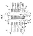
- Fig. 3 is a sectional view of an essential portion of the chain 1.
- Fig. 4 is a sectional view taken along line IV - IV of Fig. 3.
- the chain 1 is equipped with a plurality of links 2, and a plurality of connecting members 50 for connecting those links 2 in a mutually bendable manner.
- the direction parallel to the advancing direction of the chain 1 is called the chain advancing direction X; that of the directions perpendicular to the chain advancing direction X, which extends along the longitudinal direction of the connecting members 50, is called the chain width direction W; and the directions perpendicular to both the chain advancing direction X and the chain width direction W are called the perpendicular directions V.
- Each link 2 is a member formed into a sheet shape and made of a steel sheet, and includes a front end portion 5 and a rear end portion 6 or a pair of end portions arranged ahead and behind of the chain advancing direction X. Individually in the front end portions 5 and the rear end portions 6, there are formed front through holes 9 as first through holes and rear through holes 10 as second through holes.
- the links 2 are arranged in both the chain advancing direction X and the chain width direction W.
- the links 2 adjoining in the chain advancing direction X are made to correspond to each other such that the front through hole 9 of the link 2 relatively positioned on the rear side in the chain advancing direction X and the rear through hole 10 of the link 2 relatively positioned on the front side are juxtaposed to each other in the chain width direction W.
- the connecting members 50 threading those corresponding through holes 9 and 10 the links 2 adjoining in the chain advancing direction X are bendably connected to form the chain 1 having an endless shape as a whole.
- Each of the connecting members 50 includes a first pin 3 as a power transmission member and a second pin 4 as a kinematic pair member.
- the first pin 3 and the second pin 4 form a pair with each other
- the aforementioned paired first and second pins 3 and 4 make a rolling/sliding contact with each other as the corresponding links 2 are bent.
- the rolling/sliding contact is the contacting state containing at least one of the rolling contact and the sliding contact.
- the first pin 3 is a long member elongated in the chain width direction W, and has a length of about 2.5 mm to 4.0 mm in the chain advancing direction X and a length of about 5.5 mm to 8.0 mm in the perpendicular directions V.
- the periphery 11 of the first pin 3 is formed into a smooth face extending in parallel with the chain width direction W, and includes a front portion 12 as a confronting portion facing forward of the chain advancing direction X, a rear portion 13 facing backward of the chain advancing direction X, and a pair of end portions of one end portion 14 and other end portion 15 confronting each other in the perpendicular directions V.
- the front portion 12 confronts the second pin 4 paired, and makes the rolling/sliding contact at a contacting portion T (or a contacting point, as viewed in the chain width direction W) with the later-described rear portion 19 of the second pin 4.
- the rear portion 13 is made to have a flat face. This flat face 13 has a predetermined angle of inclination E with respect to a plane D normal to the chain advancing direction X. This inclination angle E is set to a value as small as about 5 to 12 degrees so that it can be thought to be substantially zero.
- the one end portion 14 constitutes that end portion of the periphery 11, which is located on one side V1 of the perpendicular directions V or radially outward of the radial directions RP1 and RP2 of the pulleys 60 and 70.
- the other end portion 15 constitutes that end portion of the periphery 11, which is located on the other side V2 of the perpendicular directions V or radially inward of the radial directions RP1 and RP2 of the pulleys 60 and 70.
- a pair of end portions 16 in the longitudinal direction of the first pin 3 are protruded outward of the chain width direction W with respect to those links 2a and 2b of each link 2, which are arranged at the paired end portions in the chain width direction W. End faces 17 are formed on those paired end portions 16.
- the one end portion 14 is made wider in the chain width direction W than the other end portion 15.
- the paired end faces 17 make frictional contact (or engagement) with the corresponding sheave faces 62a and 63a, and 72a and 73a of the individual pulleys 60 and 70.
- the first pins 3 are clamped between those corresponding sheave faces 62a and 63a, and 72a and 73a so that the power is transmitted between the first pins 3 and the individual pulleys 60 and 70.
- the first pins 3 are made of a highly strong wear resisting material such as bearing steel (SUJ2) so that their end faces 17 may contribute to direct power transmissions.
- the second pins are long members made of a material similar to that of the first pins 3 and extending in the chain width direction W.
- the second pins 4 are made so shorter than the first pins 3 that their paired end portions may not contact with the sheave faces of the individual pulleys, and are arranged ahead of the pairing first pins 3 in the chain advancing direction X.
- the second pin 4 has its periphery 18 formed into a smooth face extending in the chain width direction W.
- This periphery 18 has a rear portion 19 as an opposite portion confronting backward in the chain advancing direction X.
- an intermediate portion in the perpendicular directions V is formed into a flat face normal to the chain advancing direction X, and confronts the front portion 12 of the pairing first pin 3.
- the chain 1 is the so-called "press-fit type chain".
- the corresponding first pin 3 is loosely fitted, and the corresponding second pin 4 is press-fitted and fixed.
- the corresponding first pin 3 is press-fitted and fixed, and the corresponding second pin 4 is loosely fitted.
- the front portion 12 of the first pin 3 and the rear portion 19 of the second pin 4 make the rolling/sliding contact with each other on the contacting portion T to move as the links 2 adjoining in the chain advancing direction X are bent.
- the individual first and second pins 3 and 4 may also be loosely fitted in the corresponding front through hole 9 and rear through hole 10.
- the chain 1 is the chain of the so-called "involute type". Specifically, a curved portion 20 is formed at the front portion 12 of the first pin 3. The end portion of the curved portion 20 on the other side V2 of the perpendicular directions V is used as a predetermined starting portion F (i.e., a predetermined starting point, as viewed in the chain width direction W).
- a predetermined starting portion F i.e., a predetermined starting point, as viewed in the chain width direction W.
- the position of the starting portion F is located at a contacting portion T1, i.e., at the contacting portion T. of the first pin 3 in the straight region of the chain 1.
- This starting portion F is arranged in the front portion 12 and on the side close to the other end portion 15.
- the curved portion 20 is formed of an involute curve having a predetermined starting portion F (or starting point).
- This involute curve has a base circle G.
- This base circle G has a center G1 and a radius G2 (e.g., a base circle radius of 100 mm, for example).
- the center G1 is located in a plane normal to the chain advancing direction X and containing the contacting portion T1 of the first pin 3, and is located at a position advancing from the contacting portion T1 to the other side V2 of the perpendicular directions V.
- the base circle C and the starting portion F intersect with each other.
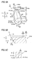
- Fig. 5A is a side elevation showing the first pin 3 along the chain width direction W;
- Fig. 5B is a sectional view taken along line VB - VB of Fig. 5A; and
- Fig. 5C is a sectional view taken along line VC - VC of Fig. 5A.
- one of the characteristics of this mode of embodiment is that a bulging curved face 21 is formed on the end face 17 of the first pin 3 and provides a contact area to contact with the corresponding sheave faces 62a and 63a, and 72a and 73a of the individual pulleys 60 and 70.
- the bulging curved face 21 is formed into an egg-like shape elongated in the perpendicular directions V, as viewed along the chain width direction W, and is made asymmetric with respect to an arbitrary plane (although not shown) normal to the perpendicular directions V.
- the bulging curved face 21 includes first and second end portions 22 and 23 in the perpendicular directions V, and a maximum width portion 24, which is the widest with respect to the chain advancing direction X.
- the first end portion 22 contains the end portion of the bulging curved face 21 on the one side V1 of the perpendicular directions V, and is close to the one end portion 14 of the periphery 11.
- the second end portion 23 contains the end portion of the bulging curved face 21 on the other side V2 of the perpendicular directions V, and is close to the other end portion 15 of the periphery 11.
- the first end portion 22 and the second end portion 23 intersect with a plane K containing the center 241 of the maximum width portion 24, individually.
- the first end portion 22, the maximum width portion 24 and the second end portion 23 are arranged on one straight line, when viewed in the chain width direction W.
- the plane K is parallel to the rear portion 13.
- the center 241 of the maximum width portion 24 and the first end portion 22 are spaced by a relatively long distance L1
- the center 241 of the maximum width portion 24 and the second end portion 23 are spaced by a relatively short distance L2.
- the aforementioned plane K contains a predetermined reference axis M.
- This reference axis M is arranged outside of the first pin 3 and close to the first end portion 22, and extends along the chain width direction W. As viewed along the chain width direction W, the reference axis M and the one end portion 14 are spaced by a predetermined distance R with reference to the perpendicular directions V.
- a line of intersection K1 between the arbitrary plane K containing the reference axis M and the end face 17 is formed into an arcuate shape having a single radius of curvature Rg (e.g., 180 mm) in that plane K.
- Rg radius of curvature
- Fig. 5B shows the intersection line K1 between the plane K extending through the first and second end portions 22 and 23 and the bulging curved face 21.
- a line of intersection N1 between an arbitrary arcuate plane N on the center of the radius of curvature of the reference axis M and the end face 17 is formed into an arcuate shape having a single radius of curvature P in that arbitrary arcuate plane N.
- Fig. 5C shows the intersection line N1 between the arcuate plane N extending through the center 241 of the maximum width portion 24 and the end face 17 as an example.
- the curvature radius P of the intersection line N1 becomes the larger as the cylindrical plane N constituting that intersection line N1 moves from the one end portion 14 toward the center 241. Moreover, the curvature radius P of the intersection line N1 becomes the smaller as the cylindrical plane N constituting that intersection line N1 moves from the center 241 toward the other end portion 15.
- the intersection line (although not shown) between a plane parallel to the chain advancing direction X and the end face 17 does not have a constant radius of curvature in that plane.
- the intersection line R1 between the arbitrary inclined face R, which is inclined by the same angle C1 as the aforementioned pulley half angle C1 with respect to a plane Q normal to the reference axis M and the end face 17 is identical, in that inclined face R, to either an outer peripheral edge 211 of the bulging curved face 21 or a shape similar to the outer peripheral edge 211 (Fig. 5A shows the intersection line R1 aligned with the outer peripheral edge 211 and the intersection line R1 on the outer side, for example).
- first-kind pins 3a as the first members
- second-kind pins 3b as the second members, which are arrayed at random in the chain advancing direction X.
- Fig. 5A, Fig. 5B and Fig. 5C show the first-kind pins 3a of the first pins, individually.
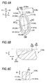
- Fig. 6A is a side elevation of the second-kind pin 3b of the first pin 3, as taken along the chain width direction W;
- Fig. 6B is a sectional view along line VIB - VIB of Fig. 6A; and
- Fig. 6C is a sectional view along line VIC - VIC of Fig. 6A.
- first-kind pins 3a and the second-kind pin 3b The constitution common between the first-kind pins 3a and the second-kind pin 3b has been described in connection with the first pin 3, and the following description is made mainly on the differences between the first-kind pin 3a and the second-kind pin 3b.
- the portion of the first-kind pin 3a near the end on the one side V1 of the perpendicular directions V is made relatively thin with respect to the chain advancing direction X
- the portion of the second-kind pin 3b near the end on the one side V1 of the perpendicular directions V is made relatively thick with respect to the chain advancing direction X.
- the first-kind pin 3a has a bulging curved face 21a formed longer in the perpendicular directions V than the bulging curved face 21b of the second-kind pin 3b.
- the distance Ra between one end portion 14a of the first-kind pin 3a and a corresponding reference axis Ma with reference to the perpendicular directions V is shorter than the distance Rb between one end portion 14b of the second-kind pin 3b and a corresponding reference axis Mb with reference to the perpendicular directions V (that is, Ra ⁇ Rb).
- the first- and second-kind pins 3a and 3b are made such that the loci of the rolling/sliding contact of the contacting portion T as the links 2 are bent are made different from each other.
- the sectional shape of a curved face 20a of the front portion 12a of the first-kind pin 3a is different from that of a curved face 20b of the front portion 12b of the second-kind pin 3b.
- the radius G2a of a base circle Ga of the involute curve of the section of the curved portion 20a of the first-kind pin 3a is made so relatively small as 40 mm.
- the radius G2b of a base circle Gb of the involute curve of the section of the curved portion 20b of the second-kind pin 3b is made so relatively large as 54 mm.
- the locus of the rolling/sliding contact of the contacting portion T of the first-kind pin 3a with reference to the first-kind pin 3a is different from that of the rolling/sliding contact of the contacting portion T of the second-kind pin 3b with reference to the second-kind pin 3b.
- the first- and second-kind pins 3a and 3b are arrayed at random in the chain advancing direction X so that the first pins 3 are made random in the contact period, for which the first pins 3 make sequential contact individually with the individual pulleys.
- the "random array” means that at least either the first-kind pins 3a or the second-kind pins 3b are irregularly arranged at least partially of the chain advancing direction X.
- the word “irregular” means the lack of at least the periodicity and the regularity.
- these pins 3a and 3b are arrayed in such an order in the chain advancing direction X as "a, b, b, a, b, b, b, a, b, b, b, b, a, b, b, b, b, b, a, b, b, b, b, b, b, b, a, b, b, b, b, b, b, b" (although the individual symbols "" are omitted).
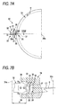
- Fig. 7A is a side elevation of an essential portion of a grinding apparatus 30 for grinding and forming the end faces of the first pins
- Fig. 7B is a sectional view taken along line VIIB - VIIB of Fig. 7A.
- the grinding apparatus 30 is provided with a carrier 32 for holding a manufacture intermediate 31 of the first pin, and a grinding wheel 34 for simultaneously grinding the paired end faces 33 and 33 of the manufacture intermediate 31 held by the carrier 32.
- the manufacture intermediate 31 is a prepared to have a long rod shape.
- the carrier 32 can be rotated on a center axis 32a.
- the outer circumference portion of the carrier 32 includes a holding portion 35 for holding the longitudinally middle portion of the manufacture intermediate 31 integrally rotatably but not relatively movably.
- the holding portion 35 holds the manufacture intermediate 31 in parallel with the center axis 32a.
- the holding portion 35 is provided in plurality (e.g., four) in the circumferential direction of the carrier 32.
- Each holding portion 35 includes a holding face 36 for holding the manufacture intermediate 31, and a push member 37 made of an elastic member and associated with the holding face 36 for clamping the manufacture intermediate 31 elastically.
- the paired end faces 33 and 33 of the manufacture intermediate 31 held by the holding portion 35 are individually protruded axially from the carrier 32.
- the grinding wheel 34 is formed into a disc shape, and can be rotated on the center axis 34a.
- the center axes 32a and 34a are made in parallel with each other.
- a circumferential groove 38 In the vicinity of the outer circumference of the grinding wheel 34, there is formed a circumferential groove 38 having a section of a generally trapezoidal shape.
- the two axial side walls of the circumferential groove 38 contain grinding faces 39 inclined in a conical face, and are formed symmetrically with each other in the axial direction of the grinding wheel 34.
- Each of the grinding faces 39 is given a radius of curvature Rg, which is equal to the aforementioned radius of curvature Rg.
- a plane S normal to the center axis 34a and the generating line of the grinding face 39 make the same angle C1 as the pulley half angle C1.
- the radius of curvature of the grinding faces 39 of the grinding wheel 34 is set suitable.
- the distance between the center axis 32a and the manufacture intermediate 31 is set to the same value R as the aforementioned distance R between the reference axis M of the first pin 3 and the one end portion 14. As this distance R is the shorter, the bulging curved face 21 formed on the end face 17 of the first pin 3 becomes the longer in the perpendicular directions V.
- This distance R is preferred to be 10 mm or less. This is because the radius of curvature near the pin crest portion exceeds 50 mm, as the distance R exceeds 10 mm, so that the edge abutment becomes more probable.
- the distance R is more preferred to be 5 mm or less. This is because the egg-like shape can be formed more definitely if the distance is 5 mm or less.
- the paired end faces 33 and 33 of the manufacture intermediate 31 are ground in the following manner.
- the carrier 32 and the grinding wheel 34 are rotationally driven on their individual center axes 32a and 34a in the same direction a by the (not-shown) motor.
- the rotating speed of the grinding wheel 34 is set constant at a relatively high value, and the rotating speed of the carrier 32 is set to a relatively low value.
- the manufacture intermediate 31 held by the holding portion 35 of the carrier 32 passes between the paired grinding faces 39 and 39.
- the paired end faces 33 and 33 of the manufacture intermediate 31 are ground in contact with the corresponding grinding faces 39.
- the surface area of the bulging curved face 21 can be sufficiently enlarged by providing the egg-like shaped bulging curved face 21 on the first pin 3.
- the contacting areas between the bulging curved face 21 and the corresponding sheave faces 62a and 63a, and 72a and 73a can be sufficiently retained to bear the loads from the sheave faces 62a and 63a, and 72a and 73a in the bulging curved face 21.
- the edge abutment can be prevented by preventing the sheave faces 62a and 63a, and 72a and 73a from contacting with the edges (or edge portions) of the end faces 17 of the first pin 3, so that the progress of the wear of the end faces 17 of the first pin 3 can be drastically reduced. Moreover, the end faces 17 can be prevented from being pried out with respect to the corresponding sheave faces 62a and 63a, and 72a and 73a.
- This wear reducing effect is prominently exhibited at the first-kind pins 3a thinned in the chain advancing direction X. Moreover, the facial pressure to act on the end faces 17 of the first pin 3 can be made so low as to lower the loads, thereby to raise the allowable transmission torque and improve the durability.
- the first end portion 22 is formed to one corresponding to the radially outer portion of the pulley.
- the edge abutment can be prevented even in case that end portion of the end face 17 of the first pin 3, which corresponds to the outside of the pulley radial direction, is thinned in the chain advancing direction X.
- the intersection line K1 between the arbitrary plane K containing the reference axis M and the bulging curved face 21 is formed into the arcuate shape having the single curvature radius Rg so that the bulging curved face 21 can be formed on the end face 17 of the first pin 3.
- the first pin 3 is exemplified by the first-and second-kind pins 3a and 3b arrayed at random in the chain advancing direction X, the moving loci of the contacting portion T accompanying the bends of the links 2 are made different between the first- and second-kind pins 3a and 3b.
- the meshing periods at the time when the first pins 3 are individually meshed sequentially by the pulleys 60 and 70 are made random.
- the distribution of those meshing noises is distributed over a wide range thereby to lower the peak value, so that the noises accompanying the drive of the chain 1 can be drastically reduced.
- the end faces 17a of the thinned first-kind pins 3a can contact with the corresponding sheave faces 62a and 63a, and 72a and 73a in the bulging curved face 21 so that they can be prevented from performing the edge abutment against the sheave faces 62a and 63a, and 72a and 73a.
- the bulging curved faces 21 can be simultaneously formed on the paired end faces 17 of the first pin 3 to reduce the dispersion of the whole length of the first pins 3.
- the moving locus of the contacting portion T with respect to the first pins 3 is made to draw the involute curve, as viewed in the chain width direction W. This can suppress the chordal vibrations in the chain 1 when the first pins are sequentially meshed by the pulleys 60 and 70. As a result, it is possible to reduce the noises at the driving time of the chain 1.
- the wear of the end faces 17 of the first pins 3 and the wears of the sheave faces 62a and 63a, and 72a and 73a can be suppressed to realize the continuously variable transmission 100 which is excellent in the durability and which can transmit a high torque quietly.
- the invention should not be limited to the aforementioned mode of embodiment but can be modified in various manners within the scope of the claims.
- the invention may be modified such that the first end portion 22 of the bulging curved face 21 contains the end portion on the other side V2 of the perpendicular directions V, and such that the second end portion 23 contains the end portions on the one side V1 of the perpendicular directions V.
- the curvature radius Rg should not be limited to the above-exemplified value but may also be larger or smaller.
- the end face 17 of the first pin 3 may be partially crowned.
- the curved portion 20 of the first pin 3 may also be formed into a curve (e. g., a curve having one or plural radii of curvature) other than the involute curve.
- the invention may also be applied to the so-called "block type power transmission chain", in which members having power transmission portions similar to the end faces of the paired first pins are arranged near the individual paired end portions of the first pins.
- the invention should not be limited to the mode, in which the groove width of both the drive pulley 60 and the driven pulley 70 is varied, but may also be modified such that only the groove width of one pulley fluctuates whereas the groove width of the other pulley is fixed. Moreover, the description has been made on the aforementioned mode, in which the groove width fluctuates continuously (without any step). However, the invention may also be applied to another power transmission device of stepwise variations or fixed type (without speed change).
Applications Claiming Priority (1)
| Application Number | Priority Date | Filing Date | Title |
|---|---|---|---|
| JP2006213881A JP4840654B2 (ja) | 2006-08-04 | 2006-08-04 | 動力伝達チェーン、動力伝達チェーンの動力伝達部材を製造する方法および動力伝達装置 |
Publications (3)
| Publication Number | Publication Date |
|---|---|
| EP1884682A2 true EP1884682A2 (fr) | 2008-02-06 |
| EP1884682A3 EP1884682A3 (fr) | 2009-07-22 |
| EP1884682B1 EP1884682B1 (fr) | 2011-11-16 |
Family
ID=38656989
Family Applications (1)
| Application Number | Title | Priority Date | Filing Date |
|---|---|---|---|
| EP07015273A Expired - Fee Related EP1884682B1 (fr) | 2006-08-04 | 2007-08-03 | Chaîne de transmission , procédé pour la fabrication d'un élément de transmission de la chaîne de transmission et dispositif de transmission |
Country Status (3)
| Country | Link |
|---|---|
| US (1) | US8038559B2 (fr) |
| EP (1) | EP1884682B1 (fr) |
| JP (1) | JP4840654B2 (fr) |
Cited By (1)
| Publication number | Priority date | Publication date | Assignee | Title |
|---|---|---|---|---|
| EP2075485A1 (fr) * | 2006-10-20 | 2009-07-01 | JTEKT Corporation | Chaîne de transmission de puissance et dispositif de transmission de puissance équipé de celle-ci |
Families Citing this family (13)
| Publication number | Priority date | Publication date | Assignee | Title |
|---|---|---|---|---|
| JP5252183B2 (ja) * | 2008-02-28 | 2013-07-31 | 株式会社ジェイテクト | 動力伝達チェーンおよびこれを備える動力伝達装置 |
| JP5152575B2 (ja) * | 2008-04-16 | 2013-02-27 | 株式会社ジェイテクト | 動力伝達チェーンおよびこれを備える動力伝達装置 |
| US8933526B2 (en) * | 2009-07-15 | 2015-01-13 | First Solar, Inc. | Nanostructured functional coatings and devices |
| JP5321366B2 (ja) * | 2009-09-04 | 2013-10-23 | 株式会社ジェイテクト | 動力伝達チェーン用ピンの製造方法 |
| JP5655287B2 (ja) * | 2009-09-24 | 2015-01-21 | 株式会社ジェイテクト | 動力伝達チェーンの組立方法 |
| JP5418124B2 (ja) * | 2009-10-07 | 2014-02-19 | 株式会社ジェイテクト | 動力伝達チェーン用ピンの製造方法 |
| CN104334917B (zh) * | 2012-07-06 | 2016-03-09 | 本田技研工业株式会社 | 金属带用元件 |
| US10184550B2 (en) * | 2014-02-24 | 2019-01-22 | Schaeffler Technologies AG & Co. KG | Plate link chain |
| JP6374727B2 (ja) * | 2014-08-06 | 2018-08-15 | 株式会社椿本チエイン | サイレントチェーン伝動装置 |
| NL2014092B1 (nl) * | 2015-01-07 | 2016-09-30 | Drive Tech Holland Ltd | Overbrengorgaan en transmissie voorzien van een dergelijke overbrengorgaan. |
| JP6747377B2 (ja) * | 2017-05-16 | 2020-08-26 | アイシン・エィ・ダブリュ株式会社 | 無段変速機および伝動ベルト |
| JP6859915B2 (ja) * | 2017-10-10 | 2021-04-14 | トヨタ自動車株式会社 | 伝動ベルト |
| DE112021001116A5 (de) * | 2020-02-19 | 2022-12-22 | Schaeffler Technologies AG & Co. KG | Wiegedruckstück für ein wiegedruckstückpaar einer laschenkette |
Citations (1)
| Publication number | Priority date | Publication date | Assignee | Title |
|---|---|---|---|---|
| WO2005045280A1 (fr) | 2003-10-29 | 2005-05-19 | Jtekt Corporation | Chaine de transmission de puissance et dispositif de transmission de puissance |
Family Cites Families (13)
| Publication number | Priority date | Publication date | Assignee | Title |
|---|---|---|---|---|
| DE2848166C2 (de) | 1978-11-07 | 1981-01-15 | P.I.V. Antrieb Werner Reimers Kg, 6380 Bad Homburg | Laschenkette für stufenlos verstellbare Kegel-Reibscheibenumschlingungsgetriebe |
| JPS5783353A (en) * | 1980-11-05 | 1982-05-25 | Nisshin Kogyo Kk | Work piece transferring apparatus of polishing machine |
| JPS6125761A (ja) * | 1984-07-16 | 1986-02-04 | Motoi Nishimura | 竪軸型平面研削盤 |
| DE3631213A1 (de) * | 1986-09-13 | 1988-03-24 | Piv Antrieb Reimers Kg Werner | Laschenkette fuer stufenlos verstellbare kegelscheibengetriebe mit asymmetrischem scheibenkeil |
| US5328412A (en) * | 1992-10-21 | 1994-07-12 | Borg-Warner Automotive, Inc. | Apparatus and method for generating a variable pulley sheave profile |
| US5399116A (en) * | 1993-08-27 | 1995-03-21 | Kennametal Inc. | Grinding wheel assembly for grinding and sizing an elastomeric belt |
| NL1000294C2 (nl) * | 1995-05-03 | 1996-11-05 | Gear Chain Ind Bv | Transmissieketting voor een kegeldrijfwerk. |
| DE10003131B4 (de) * | 1999-02-06 | 2012-03-29 | Schaeffler Technologies Gmbh & Co. Kg | Laschenkette |
| IT1306145B1 (it) * | 1999-05-21 | 2001-05-30 | Quintilio Lupi | Utensile rotativo ad azione combinata abrasiva e a frammentazione perla esecuzione di profili o di tagli su lastre di materiale fragile |
| EP1443242A3 (fr) * | 2003-01-31 | 2005-02-09 | NTRK Co., Ltd. | Composant mécanique pour chaines pour transmission continûment variable |
| JP2005308108A (ja) * | 2004-04-22 | 2005-11-04 | Koyo Seiko Co Ltd | ロードピンの製造方法 |
| NL1026773C2 (nl) * | 2004-08-03 | 2006-02-06 | Gear Chain Ind Bv | Scharniersamenstel voor een transmissieketting en transmissieketting voorzien van een dergelijk scharniersamenstel. |
| DE602005010603D1 (de) * | 2004-10-19 | 2008-12-04 | Jtekt Corp | Schleifvorrichtung und herstellungsverfahren für kraftübertragungskettenstift |
-
2006
- 2006-08-04 JP JP2006213881A patent/JP4840654B2/ja not_active Expired - Fee Related
-
2007
- 2007-08-03 EP EP07015273A patent/EP1884682B1/fr not_active Expired - Fee Related
- 2007-08-03 US US11/882,706 patent/US8038559B2/en not_active Expired - Fee Related
Patent Citations (1)
| Publication number | Priority date | Publication date | Assignee | Title |
|---|---|---|---|---|
| WO2005045280A1 (fr) | 2003-10-29 | 2005-05-19 | Jtekt Corporation | Chaine de transmission de puissance et dispositif de transmission de puissance |
Cited By (2)
| Publication number | Priority date | Publication date | Assignee | Title |
|---|---|---|---|---|
| EP2075485A1 (fr) * | 2006-10-20 | 2009-07-01 | JTEKT Corporation | Chaîne de transmission de puissance et dispositif de transmission de puissance équipé de celle-ci |
| EP2075485A4 (fr) * | 2006-10-20 | 2010-12-15 | Jtekt Corp | Chaîne de transmission de puissance et dispositif de transmission de puissance équipé de celle-ci |
Also Published As
| Publication number | Publication date |
|---|---|
| EP1884682B1 (fr) | 2011-11-16 |
| EP1884682A3 (fr) | 2009-07-22 |
| US20080051235A1 (en) | 2008-02-28 |
| JP2008039044A (ja) | 2008-02-21 |
| JP4840654B2 (ja) | 2011-12-21 |
| US8038559B2 (en) | 2011-10-18 |
Similar Documents
| Publication | Publication Date | Title |
|---|---|---|
| EP1884682B1 (fr) | Chaîne de transmission , procédé pour la fabrication d'un élément de transmission de la chaîne de transmission et dispositif de transmission | |
| EP2053271B1 (fr) | Appareil de transmission de puissance | |
| US20070191166A1 (en) | Power transmission chain and power transmission device | |
| EP1840408B1 (fr) | Chaîne et système de transmission de puissance | |
| EP2075485A1 (fr) | Chaîne de transmission de puissance et dispositif de transmission de puissance équipé de celle-ci | |
| EP2365230B1 (fr) | Chaîne et dispositif de transmission de puissance | |
| US20100035713A1 (en) | Power transmission chain and power transmission device | |
| JP4910982B2 (ja) | 動力伝達チェーンの製造方法 | |
| JP4761113B2 (ja) | 動力伝達チェーンおよびこれを備える動力伝達装置 | |
| EP1953413B1 (fr) | Chaîne de transmission de puissance et appareil de transmission de puissance | |
| JP4591764B2 (ja) | 動力伝達チェーンおよびこれを備える動力伝達装置 | |
| JP4423560B2 (ja) | 動力伝達チェーンおよびこれを備える動力伝達装置 | |
| JP2006077847A (ja) | 動力伝達チェーンおよびこれを備える動力伝達装置 | |
| JP2008151317A (ja) | 動力伝達チェーンおよび動力伝達装置 | |
| JP4770554B2 (ja) | 動力伝達チェーンおよび動力伝達装置 | |
| JP2008185119A (ja) | 動力伝達装置 | |
| JP2007271034A (ja) | 動力伝達チェーンおよびこれを備える動力伝達装置 | |
| JP2009222106A (ja) | 動力伝達チェーンおよび動力伝達装置 | |
| JP5211346B2 (ja) | 動力伝達チェーンおよび動力伝達装置 | |
| JP2008215448A (ja) | 動力伝達チェーンおよび動力伝達装置 | |
| JP2007107669A (ja) | 動力伝達チェーンおよびこれを備える動力伝達装置 | |
| JP2009228702A (ja) | 動力伝達チェーンおよび動力伝達装置 | |
| JP2006144976A (ja) | 動力伝達チェーンおよびこれを備える動力伝達装置 | |
| JP2008185166A (ja) | 動力伝達チェーンおよび動力伝達装置 | |
| JP2008190553A (ja) | 動力伝達チェーンおよび動力伝達装置 |
Legal Events
| Date | Code | Title | Description |
|---|---|---|---|
| PUAI | Public reference made under article 153(3) epc to a published international application that has entered the european phase |
Free format text: ORIGINAL CODE: 0009012 |
|
| AK | Designated contracting states |
Kind code of ref document: A2 Designated state(s): AT BE BG CH CY CZ DE DK EE ES FI FR GB GR HU IE IS IT LI LT LU LV MC MT NL PL PT RO SE SI SK TR |
|
| AX | Request for extension of the european patent |
Extension state: AL BA HR MK YU |
|
| PUAL | Search report despatched |
Free format text: ORIGINAL CODE: 0009013 |
|
| AK | Designated contracting states |
Kind code of ref document: A3 Designated state(s): AT BE BG CH CY CZ DE DK EE ES FI FR GB GR HU IE IS IT LI LT LU LV MC MT NL PL PT RO SE SI SK TR |
|
| AX | Request for extension of the european patent |
Extension state: AL BA HR MK RS |
|
| 17P | Request for examination filed |
Effective date: 20100121 |
|
| 17Q | First examination report despatched |
Effective date: 20100218 |
|
| AKX | Designation fees paid |
Designated state(s): DE FR |
|
| GRAP | Despatch of communication of intention to grant a patent |
Free format text: ORIGINAL CODE: EPIDOSNIGR1 |
|
| GRAS | Grant fee paid |
Free format text: ORIGINAL CODE: EPIDOSNIGR3 |
|
| GRAA | (expected) grant |
Free format text: ORIGINAL CODE: 0009210 |
|
| AK | Designated contracting states |
Kind code of ref document: B1 Designated state(s): DE FR |
|
| REG | Reference to a national code |
Ref country code: DE Ref legal event code: R096 Ref document number: 602007018700 Country of ref document: DE Effective date: 20120112 |
|
| PLBE | No opposition filed within time limit |
Free format text: ORIGINAL CODE: 0009261 |
|
| STAA | Information on the status of an ep patent application or granted ep patent |
Free format text: STATUS: NO OPPOSITION FILED WITHIN TIME LIMIT |
|
| 26N | No opposition filed |
Effective date: 20120817 |
|
| REG | Reference to a national code |
Ref country code: DE Ref legal event code: R097 Ref document number: 602007018700 Country of ref document: DE Effective date: 20120817 |
|
| REG | Reference to a national code |
Ref country code: FR Ref legal event code: PLFP Year of fee payment: 10 |
|
| REG | Reference to a national code |
Ref country code: FR Ref legal event code: PLFP Year of fee payment: 11 |
|
| REG | Reference to a national code |
Ref country code: FR Ref legal event code: PLFP Year of fee payment: 12 |
|
| PGFP | Annual fee paid to national office [announced via postgrant information from national office to epo] |
Ref country code: FR Payment date: 20200715 Year of fee payment: 14 Ref country code: DE Payment date: 20200722 Year of fee payment: 14 |
|
| REG | Reference to a national code |
Ref country code: DE Ref legal event code: R119 Ref document number: 602007018700 Country of ref document: DE |
|
| PG25 | Lapsed in a contracting state [announced via postgrant information from national office to epo] |
Ref country code: FR Free format text: LAPSE BECAUSE OF NON-PAYMENT OF DUE FEES Effective date: 20210831 Ref country code: DE Free format text: LAPSE BECAUSE OF NON-PAYMENT OF DUE FEES Effective date: 20220301 |