EP1839150B1 - Systeme d'enregistrement de donnees relatives au diagnostic de pannes - Google Patents
Systeme d'enregistrement de donnees relatives au diagnostic de pannes Download PDFInfo
- Publication number
- EP1839150B1 EP1839150B1 EP06711929.7A EP06711929A EP1839150B1 EP 1839150 B1 EP1839150 B1 EP 1839150B1 EP 06711929 A EP06711929 A EP 06711929A EP 1839150 B1 EP1839150 B1 EP 1839150B1
- Authority
- EP
- European Patent Office
- Prior art keywords
- node
- nodes
- storage
- data
- communication line
- Prior art date
- Legal status (The legal status is an assumption and is not a legal conclusion. Google has not performed a legal analysis and makes no representation as to the accuracy of the status listed.)
- Expired - Fee Related
Links
Images


Classifications
-
- G—PHYSICS
- G06—COMPUTING; CALCULATING OR COUNTING
- G06F—ELECTRIC DIGITAL DATA PROCESSING
- G06F11/00—Error detection; Error correction; Monitoring
- G06F11/07—Responding to the occurrence of a fault, e.g. fault tolerance
- G06F11/0703—Error or fault processing not based on redundancy, i.e. by taking additional measures to deal with the error or fault not making use of redundancy in operation, in hardware, or in data representation
- G06F11/0766—Error or fault reporting or storing
- G06F11/0787—Storage of error reports, e.g. persistent data storage, storage using memory protection
-
- G—PHYSICS
- G06—COMPUTING; CALCULATING OR COUNTING
- G06F—ELECTRIC DIGITAL DATA PROCESSING
- G06F11/00—Error detection; Error correction; Monitoring
- G06F11/07—Responding to the occurrence of a fault, e.g. fault tolerance
-
- B—PERFORMING OPERATIONS; TRANSPORTING
- B60—VEHICLES IN GENERAL
- B60R—VEHICLES, VEHICLE FITTINGS, OR VEHICLE PARTS, NOT OTHERWISE PROVIDED FOR
- B60R16/00—Electric or fluid circuits specially adapted for vehicles and not otherwise provided for; Arrangement of elements of electric or fluid circuits specially adapted for vehicles and not otherwise provided for
- B60R16/02—Electric or fluid circuits specially adapted for vehicles and not otherwise provided for; Arrangement of elements of electric or fluid circuits specially adapted for vehicles and not otherwise provided for electric constitutive elements
- B60R16/023—Electric or fluid circuits specially adapted for vehicles and not otherwise provided for; Arrangement of elements of electric or fluid circuits specially adapted for vehicles and not otherwise provided for electric constitutive elements for transmission of signals between vehicle parts or subsystems
-
- G—PHYSICS
- G06—COMPUTING; CALCULATING OR COUNTING
- G06F—ELECTRIC DIGITAL DATA PROCESSING
- G06F11/00—Error detection; Error correction; Monitoring
- G06F11/07—Responding to the occurrence of a fault, e.g. fault tolerance
- G06F11/0703—Error or fault processing not based on redundancy, i.e. by taking additional measures to deal with the error or fault not making use of redundancy in operation, in hardware, or in data representation
- G06F11/0706—Error or fault processing not based on redundancy, i.e. by taking additional measures to deal with the error or fault not making use of redundancy in operation, in hardware, or in data representation the processing taking place on a specific hardware platform or in a specific software environment
- G06F11/0736—Error or fault processing not based on redundancy, i.e. by taking additional measures to deal with the error or fault not making use of redundancy in operation, in hardware, or in data representation the processing taking place on a specific hardware platform or in a specific software environment in functional embedded systems, i.e. in a data processing system designed as a combination of hardware and software dedicated to performing a certain function
- G06F11/0739—Error or fault processing not based on redundancy, i.e. by taking additional measures to deal with the error or fault not making use of redundancy in operation, in hardware, or in data representation the processing taking place on a specific hardware platform or in a specific software environment in functional embedded systems, i.e. in a data processing system designed as a combination of hardware and software dedicated to performing a certain function in a data processing system embedded in automotive or aircraft systems
-
- G—PHYSICS
- G06—COMPUTING; CALCULATING OR COUNTING
- G06F—ELECTRIC DIGITAL DATA PROCESSING
- G06F11/00—Error detection; Error correction; Monitoring
- G06F11/07—Responding to the occurrence of a fault, e.g. fault tolerance
- G06F11/0703—Error or fault processing not based on redundancy, i.e. by taking additional measures to deal with the error or fault not making use of redundancy in operation, in hardware, or in data representation
- G06F11/0706—Error or fault processing not based on redundancy, i.e. by taking additional measures to deal with the error or fault not making use of redundancy in operation, in hardware, or in data representation the processing taking place on a specific hardware platform or in a specific software environment
- G06F11/0748—Error or fault processing not based on redundancy, i.e. by taking additional measures to deal with the error or fault not making use of redundancy in operation, in hardware, or in data representation the processing taking place on a specific hardware platform or in a specific software environment in a remote unit communicating with a single-box computer node experiencing an error/fault
-
- G—PHYSICS
- G07—CHECKING-DEVICES
- G07C—TIME OR ATTENDANCE REGISTERS; REGISTERING OR INDICATING THE WORKING OF MACHINES; GENERATING RANDOM NUMBERS; VOTING OR LOTTERY APPARATUS; ARRANGEMENTS, SYSTEMS OR APPARATUS FOR CHECKING NOT PROVIDED FOR ELSEWHERE
- G07C5/00—Registering or indicating the working of vehicles
- G07C5/008—Registering or indicating the working of vehicles communicating information to a remotely located station
-
- G—PHYSICS
- G07—CHECKING-DEVICES
- G07C—TIME OR ATTENDANCE REGISTERS; REGISTERING OR INDICATING THE WORKING OF MACHINES; GENERATING RANDOM NUMBERS; VOTING OR LOTTERY APPARATUS; ARRANGEMENTS, SYSTEMS OR APPARATUS FOR CHECKING NOT PROVIDED FOR ELSEWHERE
- G07C5/00—Registering or indicating the working of vehicles
- G07C5/08—Registering or indicating performance data other than driving, working, idle, or waiting time, with or without registering driving, working, idle or waiting time
- G07C5/0841—Registering performance data
- G07C5/085—Registering performance data using electronic data carriers
-
- G—PHYSICS
- G07—CHECKING-DEVICES
- G07C—TIME OR ATTENDANCE REGISTERS; REGISTERING OR INDICATING THE WORKING OF MACHINES; GENERATING RANDOM NUMBERS; VOTING OR LOTTERY APPARATUS; ARRANGEMENTS, SYSTEMS OR APPARATUS FOR CHECKING NOT PROVIDED FOR ELSEWHERE
- G07C2205/00—Indexing scheme relating to group G07C5/00
- G07C2205/02—Indexing scheme relating to group G07C5/00 using a vehicle scan tool
Definitions
- the present invention generally relates to a fault diagnosis data recording system and method, and more particularly to a fault diagnosis data recording system and a fault diagnosis data recording method which are appropriate for use in storing at least a part of result data of a fault detection performed by one node into a storage unit among a plurality of nodes interconnected by a communication line.
- a control unit having a data communication capability among the plurality of control units is used to transmit data, indicated by the result of the fault detection performed by each control unit, to an external device outside the system.
- a conceivable method for storing the diagnosis data, created by the fault detection performed by the control unit (node) is that each of the plurality of control units is provided with a memory respectively, and the diagnostic data created by one control unit is always stored in its memory of the control unit (self-node storage).
- a conceivable method for avoiding such situations is to provide a memory having a large storage capacity for each of the plurality of control units.
- a conceivable method for avoiding such situations is to provide a memory having a large storage capacity for each of the plurality of control units.
- Another problem of the increase in the cost and the loading space will arise.
- An object of the present invention is to provide an improved fault diagnosis data recording system and method in which the above-mentioned problems are eliminated.
- each node in the plurality of nodes interconnected by the multiplex communication line is configured to store at least the part of the result data of the fault detection performed by the self node, into the storage unit of one of the plurality of nodes other than the self node. For this reason, even when a certain node among the plurality of nodes cannot store the diagnosis data created by the fault detection, the diagnosis data can be stored by another node among the plurality of nodes different from that node. And, even if that node has a storage unit with a low storage capacity, it is possible to acquire safely and reliably the stored diagnosis data created by the fault detection performed by that node.
- the above-mentioned fault diagnosis data recording system of the invention may be configured so that identification information of the self node is associated with the result data of the fault detection performed by the self node, and the identification information is further stored in the storage unit.
- the above-mentioned fault diagnosis data recording system of the invention may be configured so that the one of the plurality of nodes other than the self node is set up beforehand in correspondence with the self node.
- the above-mentioned fault diagnosis data recording system of the invention may be configured so that the self node is configured to transmit the result data from the self node to the one of the plurality of nodes through the multiplex communication line, and the one of the plurality of nodes other than the self node is configured to receive the result data through the multiplex communication line and store the received result data into the storage unit.
- the above-mentioned fault diagnosis data recording system of the invention may be configured so that the self node is configured to transmit the result data from the self node to two or more other nodes of the plurality of nodes through the multiplex communication line, and wherein each of the other nodes of the plurality of nodes is configured to receive the result data through the multiplex communication line and temporarily store the received result data into a storage unit of that node, respectively, and wherein each of the other nodes is configured to perform, after the temporary storage, arbitration of the temporarily stored result data according to a predetermined rule, so that one of the other nodes which is chosen by the arbitration finally stores the temporarily stored result data in the storage unit.
- the above-mentioned fault diagnosis data recording system of the invention may be configured so that the remaining nodes of the other nodes which are not chosen by the arbitration are configured to erase the result data temporarily stored in the storage unit respectively.
- the above-mentioned fault diagnosis data recording system of the invention may be configured so that each of the plurality of nodes is configured to receive a request from an external diagnostic device connected to the multiplex communication line, and transmit to the external diagnostic device the result data stored in a storage unit of that node, in response to the received request.
- a request for storage of diagnosis data created by a fault detection performed by one node is transferred from the node to another node among the plurality of nodes interconnected by the multiplex communication line, and it is possible to safely and reliably acquire the stored diagnosis data even when the diagnosis data is created by the fault detection performed by a node having a storage unit with a low storage capacity.
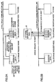
- FIG. 1 shows the composition of a fault diagnosis data recording system of an example useful for understanding the invention and an embodiment of the invention, which is installed in an automotive vehicle.
- the fault diagnosis data recording system of this example and this embodiment comprises a plurality of nodes 10 (which are in this example and this embodiment three nodes) and a multiplex communication line 12 which interconnects the plurality of nodes 10.
- the multiplex communication line 12 is a shared bus which is composed of a single wire line or twisted pair wire, such as that used in CAN (Controller Area Network).
- the multiplex communication line 12 makes it possible to transmit the data sent from each node 10 by a time-division multiplex scheme according to a predetermined communication protocol (multiplex transmission).
- each node 10 can start the transmission of data from the self node to the multiplex communication line 12 when other data is not transmitted to the multiplex communication line 12.
- the data transmission is performed according to the transmission priority of each node.
- the node 10 of concern is set in a waiting state for a fixed period of time and thereafter the data transmission is performed.
- the data sent from each node 10 is transmitted to other nodes 10 or an external diagnostic tool 20 (which will be described below) via the multiplex communication line 12.
- Each node 10 is constituted by an ECU which is an electronic control unit provided in one of various control units of the vehicle, or an intelligent sensor provided in the vehicle.
- each node 10 may be constituted by any of a steering angle sensor which outputs a signal indicative of the steering angle, a yaw rate sensor which outputs a signal indicative of the yaw rate created around the central axis of the center of gravity of the vehicle.
- each node 10 may be constituted by any of an engine ECU which performs engine control based on the throttle opening ratio, the accelerator opening ratio, the engine water temperature, etc., a VSC (vehicle stability control) ECU which is provided to stabilize the cornering action of the vehicle based on the wheel speed, the yaw rate, the steering angle, etc., a transmission ECU which controls the shift position of the vehicle based on the shift operation position, etc., a brake ECU which controls the braking force of the vehicle based on the brake treading force, the steering angle, etc., a power-steering ECU which controls steering assistant power based on the steering angle, etc., and an automatic air-conditioner ECU which controls air conditioning in the vehicle based on the air-conditioner operation switch, the in-vehicle temperature, etc.
- an engine ECU which performs engine control based on the throttle opening ratio, the accelerator opening ratio, the engine water temperature, etc.
- VSC vehicle stability control
- a transmission ECU which controls the shift position
- Each node 10 comprises a microcomputer having a controller, and a communication module linked to the microcomputer, respectively.
- the microcomputer controls the controller according to the common communications protocol in the network which is composed of the multiplex communication line 12 and the plurality of nodes 10, so that the output data being outputted from the self node 10 are digitized for transmission to another node 10 via the multiplex communication line 12, and the input data being received from another node 10 via the multiplex communication line 12 are decoded for the use for control of the self node.
- the communication module is controlled by the controller, so that the communication module transmits the data converted by the microcomputer to the multiplex communication line 12 in order to transmit the data of the self node 10 to another node 10, and receives the data transmitted from another node 10 to the self node 10.
- Each node 10 performs control of the self node based on the states of the sensors or switches linked to the self node 10 and further based on the data transmitted from other nodes 10, respectively.
- the data which are transmitted by each node 10 to the multiplex communication line 12 are constituted by a predetermined data frame.
- This data frame is, for example, composed of the start-of-frame (SOF) which indicates the beginning of the data being transmitted, the frame ID which indicates the identification information (also indicates the priority of data transmission) for identifying the kind of the data being transmitted and distinguishing from other kinds of data, the data length code (DLC) which indicates the length of the data being transmitted, and the data field which indicates the contents of the data being transmitted (e.g., the information on the wheel speed, the control command value of the driving torque, etc.), the CRC field for checking a transmission error, the field for checking that reception of the data has been completed normally, and the end-of-frame (EOF) which indicates the end of the data being transmitted.
- SOF start-of-frame
- DLC data length code
- EEF end-of-frame
- each node 10 has a function of detecting whether a certain fault arises in the self node 10, such as occurrence of abnormal data which cannot happen in the normal state, respectively. Moreover, each node 10 has a function of detecting the date/time of occurrence of the fault, the control data used for control of the self node, and the vehicle state data which indicate the state of the vehicle operation (for example, engine speed (rpm), various temperature data, vehicle speed, vehicle position, shift position, and accelerator opening ratio, which will be collectively called the diagnosis data).
- the diagnosis data for example, engine speed (rpm), various temperature data, vehicle speed, vehicle position, shift position, and accelerator opening ratio
- Each node 10 has a non-volatile memory 14, respectively.
- the contents of detection at the time of fault being detected are stored in the memory 14 as the fault diagnostic code, and the diagnosis data of the control data or the vehicle state data at the time of detection of the fault are also stored in the memory 14.
- the connector to which the external diagnostic tool 20 can be connected is disposed in the vehicle at the position where the attachment and detachment work can be easily performed.
- the external diagnostic tool 20 is connected to the multiplex communication line 12 via the connector, and the external diagnostic tool 20 is further connected to each node 10 via the multiplex communication line 12.
- the external diagnostic tool 20 is a device which is connected to the multiplex communication line 14 when a fault occurring in each node 10 should be diagnosed, performs transmission and reception of data with each node 10 in the connected state, and carries out the fault diagnosis of that node 10.
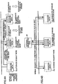
- FIG. 2A shows the step of storing the diagnosis data in the system of this example
- FIG. 2B shows the step of reading the stored diagnosis data, in the system of this example, respectively.
- FIG. 3 is a flowchart for explaining the control procedure of the fault diagnosis data recording method performed by the system of this example.
- each node 10 can detect a fault in the self node, respectively.
- the node 10 detects the fault of the self node (step 100 shown in FIG. 3 ). Then, the node 10 detects and prepares the diagnosis data including the control data and the vehicle state data at the time of the detection time together with the contents of the detected fault (step 102).
- the prepared diagnosis data is temporarily stored in the volatile memory (not shown) of this node 10 and continuously retained in the volatile memory until a request for storage of the diagnosis data is sent to another node 10.
- the nodes 10 which detect the fault of the self node there is at least one node 10 which transfers a request for storing the diagnosis data containing the control data detected by the self node, into the memory 14 of another node 10, to another node 10 other than the self node 10.
- the node 10 which detects the fault of the self node and requests the storage of the diagnosis data to another node 10 is referred to as storage request node 10a
- the node 10 which receives the request of the storage of the diagnosis data from another node 10 and performs the storage of the diagnosis data into the memory 14 of the self node 10 is referred to as storage execution node 10b, respectively.
- the node 10 having the memory 14 with a comparatively small storage capacity is set to the storage request node 10a, and the node 10 having the memory 14 with a comparatively large storage capacity is set to the storage execution node 10b.
- one storage execution node 10b which should receive the request of storage the diagnosis data from the storage request node 10a is predetermined, and the node 10 stores beforehand the identification information of the storage execution node 10b to which the request for storage of the diagnosis data is transmitted when the node 10 becomes the storage request node 10a.
- the same node 10 is predetermined as the storage execution node 10b, respectively.
- the storage request node 10a transmits a predetermined data frame to the multiplex communication line 12 so that the node 10a requests the storage execution node 10b corresponding to the self node to store the diagnosis data of the node 10a, if the diagnosis data at the time of detection of the fault of the self node is detected (step 104).
- This data frame contains at least the header which indicates the identification information of the storage execution node 10b which is the data receiver, the diagnosis data being detected, and the identification information of the storage request node 10a which is the data sender.
- the data frame sent to the multiplex communication line 12 from the storage request node 10a is received by the storage execution node 10b. And this data frame is not received by the nodes 10 which are different from the storage execution node 10b.
- the storage execution node 10b receives the data frame, if the data frame which specifies the self node flows into the multiplex communication line 12 (step 110).
- the storage execution node 10b associates the diagnosis data contained in the data frame with the identification information of the storage request node 10a of the data sender, and stores the same in the memory 14 thereof (step 112).
- the vehicle owner When the fault is detected by the storage request node 10a and the diagnosis data created by the fault detection is stored in the memory 14 of the storage execution node 10b, the vehicle owner recognizes that a certain fault has arisen on the vehicle and grasps that the fault diagnosis should be performed to remove the fault from the vehicle. And the vehicle owner who has grasped the situation or workers of a repair factory to which the repair of the vehicle is requested by the vehicle owner, will establish the connection of the external diagnostic tool 20 and the multiplex communication line 12 through the connector.
- the external diagnostic tool 20 is provided beforehand with a map which defines for every storage request node 10a the relation of the storage execution node 10b which should store the diagnosis data of the storage request node 10a. If a ready state of the external diagnostic tool 20 where the fault diagnosis can be started arises by a predetermined operation with the external diagnostic tool 20 being connected to the multiplex communication line 12 (YES of step 120), the external diagnostic tool 20 transmits to the multiplex communication line 12 the data frame which requests the storage execution node 10b, corresponding to that storage request node 10a, to perform data transmission in order to read the diagnosis data of the storage request node 10a (step 122).
- This data frame may be in conformity with the original protocol defined by the international standard ISO15765, or may be in conformity with the specifically defined protocol.
- This data frame contains at least the identification information of the storage execution node 10b which is the request receiver, and the identification information of the storage request node 10a which has detected the diagnosis data.
- the data frame sent to the multiplex communication line 12 from the external diagnostic tool 20 is received by the storage execution node 10b specified in the data frame.
- the storage execution node 10b receives the data frame, if the data frame which specifies the self node flows into the multiplex communication line 12.
- the storage execution node 10b transmits the frame data of the diagnosis data of the specified storage request node 10a, stored in the memory 14 of the self node, to the external diagnostic tool 20 through the multiplex communication line 12 (step 114).
- This data frame may be in conformity with the original protocol defined by the international standard ISO15765, or may be in conformity with the specifically defined protocol.
- the external diagnostic tool 20 receives the diagnosis data of the storage request node 10a which is transmitted from the storage execution node 10b by a predetermined operation (step 124). And the external diagnostic tool 20 stores the received diagnosis data in its memory, and performs the fault diagnosis of the vehicle based on the diagnosis data, so that a part of the vehicle where the fault arises is specified (step 126).
- Workers of the vehicle repair factory or the vehicle owner can grasp the faulty part of the vehicle through the external diagnostic tool 20 which performs the fault diagnosis.
- the fault diagnosis data recording system of this example when a fault arises in a certain node 10, it is possible to store the diagnosis data related to the fault into the memory 14 of another node 10 which is predetermined for that node, instead of the memory 14 of that node 10. In other words, a request for storage of the diagnosis data related to the fault can be transferred from the node 10 to another node 10 through the multiplex communication line 12.
- the diagnosis data can be safely stored in the memory 14 of another node 10. And, at the time of subsequent fault diagnosis, the stored diagnosis data can be read from the memory 14 of another node 10 certainly. Therefore, according to the system of this example, it is possible to safely and reliably acquire the stored diagnosis data even when the diagnosis data is created by the fault detection performed by a node having a storage unit with a low storage capacity, without increasing the memory space of the node.
- a single storage execution node 10b which should request the storage of diagnosis data created by detection of the fault of the self node is predetermined for every storage request node 10a, and the storage execution node 10b which receives the request for the storage of the diagnosis data from the storage request node 10a does perform the storage of the diagnosis data in the memory of the self node.
- predetermination of a single storage execution node 10b for every storage request node 10a is not used. Rather, all the nodes 10 other than the storage request node 10a on the multiplex communication line 12, each of which has the memory 14 in which diagnosis data can be stored, are considered as candidate storage execution nodes 10c to which the storage of diagnosis data is requested. After the request for the storage is received, arbitration of storage between the candidate storage execution nodes 10c is carried out in order to determine one of the candidate storage execution nodes 10c which finally stores the diagnosis data into the memory 14 of that node.
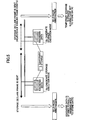
- FIG. 4A shows the step of storing diagnosis data, created by a fault detection performed by the node 10, into the other node 10
- FIG. 4B shows the step of reading the stored diagnosis data from the other node 10, which steps are performed by the fault diagnosis data recording system of this embodiment.
- the elements which are essentially the same as corresponding elements in FIG. 2A and FIG. 2B are designated by the same reference numerals, and a description thereof will be omitted.
- FIG. 5 shows the step of performing the arbitration of storage between candidate storage execution nodes 10c which is performed by the fault diagnosis data recording system of this embodiment.
- each node 10 can detect a fault of the self node, respectively.
- the node 10 detects the fault of the self node. Then, the node 10 detects and prepares the diagnosis data including the control data and the vehicle state data at the time of the detection together with the contents of the detected fault.
- the prepared diagnosis data is temporarily stored in the volatile memory (not shown) of the node 10 and continuously retained in the volatile memory until a request for storage of the diagnosis data is sent to another node 10.
- a storage execution node is not predetermined for every storage request node 10a, unlike the system of the above-mentioned embodiment.
- the storage request node 10a transmits a predetermined data frame to the multiplex communication line 12 so that the node 10a requests the candidate storage execution nodes 10c on the multiplex communication line 12 to store the diagnosis data.
- This data frame contains at least the header which indicates an arbitrary data receiver node, the diagnosis data being detected, and the identification information of the storage request node 10a which is the data sender.
- the data frame sent to the multiplex communication line 12 from the storage request node 10a is received by all the nodes, other than the storage request node 10a, on the multiplex communication line 12 (the candidate storage execution nodes 10c).
- Each of the candidate storage execution nodes 10c receives the data frame respectively, if the above-mentioned data frame flows into the multiplex communication line 12.
- Each of the candidate storage execution nodes 10c respectively performs, upon reception of the data frame from the storage request node 10a, the processing (temporary storage processing) in which the diagnosis data contained in the data frame is associated with the identification information of the storage request node 10a of the data sender, and temporarily stored into the memory 14 of the self node.
- the candidate storage execution nodes 10c which perform the temporary storage processing for the diagnosis data received from the storage request node 10a carry out the arbitration of storage therebetween in order to determine one of the nodes 10c which finally stores the diagnosis data therein.
- each of the candidate storage execution nodes 10c has a function (storage declaration frame outputting function) which transmits, when the temporary storage of the diagnosis data from the storage request node 10a to the memory 14 is actually completed, a predetermined data frame (which is called storage declaration frame) which indicates that the self node 10 has completed the temporary storage, to the multiplex communication line 12.
- each of the nodes 10 on the multiplex communication line 12 has a function which monitors the storage declaration frame which flows into the multiplex communication line 12. This function is to distinguish whether the self node 10 or another node 10 has transmitted the storage declaration frame to the multiplex communication line 12 completely.
- the node 10 In the case where the self node 10 is one of the candidate storage execution nodes 10c, the node 10 outputs, when any storage declaration frame is not flowing into the multiplex communication line 12 and the node 10 has completed the temporary storage of the diagnosis data received from the storage request node 10a, a storage declaration frame to the multiplex communication line 12.
- the node 10 when the self node 10 receives the storage declaration frame which has flowed into the multiplex communication line 12, the node 10 inhibits outputting of a storage declaration frame to the multiplex communication line 12, even if the self node 10 has completed the temporary storage of the diagnosis data received from the storage request node 10a.
- this arbitration method among all the candidate storage execution nodes 10c that receive the data frame from the storage request node 10a, the node where the temporary storage of the diagnosis data is completed and the storage declaration frame is outputted to the multiplex communication line 12 for the first time is chosen as the node (winning node) which stores the diagnosis data finally.
- a winning node is selected according to the arbitration rule conforming to the communications protocol of the multiplex communication line 1 used for the system of this embodiment. For example, the smaller one of the identification number of the node 10 of the data sender contained in the data frame is preferentially chosen as a winning node.
- the only candidate storage execution node 10c which has outputted the storage declaration frame and is chosen as the winning node associates the temporarily stored diagnosis data with the identification information of the storage request node 10a and finally stores the same into the memory 14.
- the nodes 10c (losing nodes) which cannot output storage declaration frames and are not chosen as a winning node from among the candidate storage execution nodes 10c erase both the temporarily stored diagnosis data and the identification information of the storage request node 10a of the data sender in the memory 14.
- the vehicle owner When the fault is detected by the storage request node 10a and the diagnosis data are stored into the memory 14 of any of the candidate storage execution nodes 10c, the vehicle owner recognizes that a certain fault has arisen in the vehicle and grasps that the fault diagnosis should be performed to remove the fault from the vehicle.
- the vehicle owner who has grasped the situation or workers of a repair factory to which the repair of the vehicle is requested by the vehicle owner will establish the connection of the external diagnostic tool 20 and the multiplex communication line 12 through the connector.
- the external diagnostic tool 20 is not provided with a map which defines the relation of the storage request node 10a and the storage execution node 10b as in the above-mentioned example.
- the external diagnostic tool 20 sends a data frame which requests transmission of the diagnosis data of the storage request node 10a, to the multiplex communication line 12 so that the diagnosis data of the storage request node 10a can be read out.
- This data frame contains at least the identification information of the storage request node 10a which has detected the diagnosis data.
- the data frame sent to the multiplex communication line 12 from the external diagnostic tool 20 is received by all the nodes 10 on the multiplex communication line 12.
- Each of the nodes 10 respectively determines, upon reception of the data frame from the external diagnostic tool 20, whether the diagnosis data which is detected by the storage request node 10a is finally stored in the memory 14 of the self node 10, based on the identification information of the storage request node 10a contained in the data frame.
- the self node 10 is a winning node which has performed the final storage of the diagnosis data, and the diagnosis data which is actually stored in the memory 14 of the self node 10 is transmitted to the external diagnostic tool 20 via the multiplex communication line 12.
- the external diagnostic tool 20 stores the diagnosis data into the memory when the diagnosis data of the storage request node 10a sent from the candidate storage execution node 10c which is the winning node is received by a predetermined operation. And the external diagnostic tool 20 performs the fault diagnosis of the vehicle based on the stored data so that a faulty part of the vehicle is specified.
- Workers of a vehicle repair factory or the vehicle owner can grasp the faulty part of the vehicle through the external diagnostic tool 20 which performs the fault diagnosis.
- the diagnosis data related to the fault can be stored into the memory 14 provided in another node 10 in the system of this embodiment. Namely, a request for storage of the diagnosis data related to the fault can be transferred from the node 10 to another node 10 through the multiplex communication line 12.
- the diagnosis data can be safely stored in the memory 14 of another node 10. And, at the time of subsequent fault diagnosis, the stored diagnosis data can be read from the memory 14 of another node 10 certainly.
- a single storage execution node 10b which should request the storage of diagnosis data created by detection of a fault of the self node is not predetermined for every storage request node 10a.
- the arbitration is carried out between the candidate storage execution nodes 10c to which the storage of the diagnosis data is requested from the storage request node 10a, and one of the candidate storage execution nodes 10c that finally stores the diagnosis data into the memory 14 of that node is selected.
- the storage request node 10a it is unnecessary for the storage request node 10a to store beforehand the identification information of the node 10 which is the requested storage execution node for storing the diagnosis data.
- the storage request node 10a it is not necessary to change the correspondence relation between the storage request node 10a and the storage execution node 10b separately as in the previous example. It is possible for the system of this embodiment to construct the system with good expandability.
- the arbitration is carried out between the candidate storage execution nodes 10c which has carried out the temporary storage of the diagnosis data of the storage request node 10a in the memory 14, and the node 10c that has completed the temporary storage of the diagnosis data and has outputted the storage declaration frame to the multiplex communication line 12 for the first time among the candidate storage execution nodes 10c is chosen as a winning node which finally stores the diagnosis data.
- the node 10 having the memory 14 with a small storage capacity is not chosen as a winning node, and the node 10 which has completed the temporary storage may be chosen as a winning node which performs the final storage.
- the problem may arise in that if the memory of the storage execution node 10b has a too small storage capacity the diagnosis data of the storage request node 10a is not fully stored in the memory 14 of the storage execution node 10b.
- one of the candidate storage execution nodes 10c which have the memory 14 with a sufficient storage capacity to store all the diagnosis data is chosen as a winning node. It is possible for the system of this embodiment to obviate the above-mentioned problem, and the diagnosis data of the storage request node 10a can be reliably acquired with a good probability at the time of the fault diagnosis.
- the candidate storage execution node 10c which has outputted the storage declaration frame to the multiplex communication line 12 for the first time is chosen as a winning node that finally stores the diagnosis data. Even if only one candidate storage execution node 10c exists on the multiplex communication line 12 other than the storage request node 10a, the candidate storage execution node 10c can be selected as a winning node. Therefore, according to the system of this embodiment, if the number of the candidate storage execution nodes 10c which are connected to the multiplex communication line 12 is more than one, the final storage of the diagnosis data of the storage request node 10a can be carried out regardless of the number of the nodes 10c. Consequently, it is possible to carry out the final storage of the diagnosis data of the storage request node 10a with good flexibility of the system configuration and scale.
- the external diagnostic tool 20 is not provided with the map which defines the correspondence relation of the storage request node 10a and the storage execution node 10b as in the previous example. Namely, a read request of the diagnosis data of the storage request node 10a is transmitted by the external diagnostic tool 20 to, not the specific node 10, but all the nodes 10 on the multiplex communication line 12, and the candidate storage execution node 10c which has completed the final storage of the diagnosis data transmits the diagnosis data to the external diagnostic tool 20 via the multiplex communication line 12.
- the external diagnostic tool 20 it is unnecessary for the external diagnostic tool 20 to store beforehand the map which defines the relation between the storage request node 10a and the storage execution node 10b. Therefore, when adding new node 10 on the multiplex communication line 12 or deleting the node 10 on the multiplex communication line 12, or when there is a node 10 which is installed or not installed depending on the type of the vehicle, it is not necessary to change the correspondence relation between the storage request node 10a and the storage execution node 10b separately as in the previous example. It is possible for the system of this embodiment to construct the system with good expandability.
- the system in which the external diagnostic tool 20 does not have the map which defines the correspondence relation between the storage request node 10a and the storage execution node 10b may be applied to the system of the previously described example. Also in such a case, it is possible to secure the expandability of the system to the change in the nodes 10 on the multiplex communication line 12 to some extent.
- the external diagnostic tool 20 corresponds to the external diagnostic device in the claims
- the memory 14 provided in the node 10 corresponds to the storage unit in the claims, respectively.
- all the diagnosis data which are detected by the storage request node 10a are stored into the memory 14 of the other node 10.
- the fault diagnosis data recording system may be configured so that, when the available storage capacity of the memory of each node 10 is insufficient, the diagnosis data are divided into pieces of the diagnosis data and stored into the memories 14 of the plurality of other nodes 10.
- the fault diagnosis data recording system may be configured so that, only when the available storage capacity of the memory of the storage request node 10a is insufficient, the remaining diagnosis data that cannot stored in the memory of the storage request node 10a are stored in the memories 14 of the other nodes 10.
- the plurality of electronic control units provided in the automotive vehicle are interconnected by the multiplex communication line 12.
- the present invention is not limited to this example and this embodiment.
- the fault diagnosis data recording system of the invention may be applied to not only the automotive vehicle but also a plurality of nodes interconnected by the multiplex communication line 12 in other systems different from the automotive vehicle.
Claims (9)
- Système d'enregistrement de données de diagnostic de pannes destiné à être utilisé dans un véhicule automobile, comprenant :une pluralité de noeuds (10) du véhicule interconnectés par une ligne de communication multiplex (12) dans le véhicule, chacun de la pluralité de noeuds étant configuré pour effectuer une détection de pannes du noeud respectif et comportant une unité de stockage (14) pour stocker au moins une partie de données de résultat de la détection de pannes effectuée par un autre noeud parmi la pluralité de noeuds du véhicule, dans lequelun premier noeud (10a) parmi la pluralité de noeuds du véhicule, ledit premier noeud comportant une unité de stockage ayant une capacité de stockage insuffisante pour stocker toutes les données de résultat de la détection de pannes effectuée par le premier noeud, est configuré pour transmettre lesdites données de résultat de la détection de pannes effectuée par le premier noeud à une pluralité de deuxièmes noeuds (10b, 10c) parmi la pluralité de noeuds du véhicule via la ligne de communication multiplex,chacun de la pluralité de deuxièmes noeuds (10b ; 10c) parmi la pluralité de noeuds du véhicule est configuré pour recevoir les données de résultat de la détection de pannes effectuée par le premier noeud via la ligne de communication multiplex, et pour stocker temporairement les données de résultat reçues dans son unité de stockage respective, etledit système d'enregistrement de données est configuré pour effectuer, après le stockage temporaire des données de résultat au niveau de la pluralité de deuxièmes noeuds, un processus d'arbitrage entre chacun de la pluralité de deuxièmes noeuds pour déterminer, conformément à une règle prédéterminée, lequel parmi la pluralité de deuxièmes noeuds est choisi pour stocker finalement les données de résultat stockées temporairement dans son unité de stockage respective.
- Système d'enregistrement de données de diagnostic de pannes selon la revendication 1, dans lequel des informations d'identification du premier noeud sont associées aux données de résultat de la panne détectée par le premier noeud, et les informations d'identification sont en outre stockées dans l'unité de stockage de chacun de la pluralité de deuxièmes noeuds.
- Système d'enregistrement de données de diagnostic de pannes selon la revendication 1 ou 2, dans lequel
chacun de la pluralité de deuxièmes noeuds est configuré pour transmettre, après le stockage temporaire des données de résultat dans son unité de stockage respective, une trame de déclaration de stockage indiquant que le deuxième noeud respectif a terminé le stockage temporaire des données de résultat à la ligne de communication multiplex. - Système d'enregistrement de données de diagnostic de pannes selon l'une quelconque des revendications 1 à 3, dans lequel les noeuds restants de la pluralité de deuxièmes noeuds, qui ne sont pas choisis par le processus d'arbitrage, sont configurés pour effacer les données de résultat temporairement stockées dans leurs unités de stockage respectives.
- Système d'enregistrement de données de diagnostic de pannes selon l'une quelconque des revendications 1 à 4, dans lequel
chacun de la pluralité de noeuds du véhicule est configuré pour recevoir une demande à partir d'un dispositif de diagnostic externe (20) connecté à la ligne de communication multiplex (12), et
le deuxième noeud de la pluralité de deuxièmes noeuds, qui est choisi par le processus d'arbitrage, est configuré pour transmettre, en réponse à la demande reçue, les données de résultat finalement stockées dans son unité de stockage respective via la ligne de communication multiplex au dispositif de diagnostic externe (20). - Procédé d'enregistrement de données de diagnostic de pannes destiné à être utilisé dans un véhicule automobile, qui comprend une pluralité de noeuds (10) du véhicule interconnectés par une ligne de communication multiplex (12) dans le véhicule, chacun de la pluralité de noeuds étant configuré pour effectuer une détection de pannes du noeud respectif et comportant une unité de stockage (14) pour stocker au moins une partie de données de résultat de la détection de pannes effectuée par un autre noeud parmi les pluralité de noeuds du véhicule,
ledit procédé comprenant les étapes consistant :à détecter, au niveau d'un premier noeud (10a) parmi la pluralité de noeuds du véhicule, ledit premier noeud comportant une unité de stockage ayant une capacité de stockage insuffisante pour stocker toutes les données de résultat de la détection de pannes effectuée par le premier noeud, une panne dans le premier noeud en effectuant la détection de pannes par le premier noeud, et à transmettre lesdites données de résultat de la détection de pannes effectuée par le premier noeud à une pluralité de deuxièmes noeuds (10b, 10c) parmi la pluralité de noeuds du véhicule via la ligne de communication multiplex,à recevoir, par chacun de la pluralité de deuxièmes noeuds (10 ; 10c) parmi la pluralité de noeuds du véhicule, via la ligne de communication multiplex, et à stocker temporairement dans son unité de stockage respective les données de résultat de la détection de pannes effectuée par le premier noeud, età effectuer, après le stockage temporaire des données de résultat au niveau de la pluralité de deuxièmes noeuds, un processus d'arbitrage entre chacun de la pluralité de deuxièmes noeuds pour déterminer, conformément à une règle prédéterminée, lequel parmi la pluralité de deuxièmes noeuds est choisi pour stocker finalement les données de résultat temporairement stockées dans son unité de stockage respective. - Procédé d'enregistrement de données de diagnostic de pannes selon la revendication 6, comprenant en outre l'étape consistant :à transmettre, par chacun de la pluralité de deuxièmes noeuds, après le stockage temporaire des données de résultat dans son unité de stockage respective, une trame de déclaration de stockage indiquant que le deuxième noeud respectif a terminé le stockage temporaire des données de résultat à la ligne de communication multiplex.
- Procédé d'enregistrement de données de diagnostic de pannes selon la revendication 6 ou 7, comprenant en outre l'étape consistant :à effacer, par les noeuds restants de la pluralité de deuxièmes noeuds, qui ne sont pas choisis par le processus d'arbitrage, les données de résultat stockées temporairement dans leurs unités de stockage respectives.
- Procédé d'enregistrement de données de diagnostic de pannes selon l'une quelconque des revendications 6 à 8, comprenant en outre les étapes consistant :à recevoir, par chacun de la pluralité de noeuds du véhicule, une demande à partir d'un dispositif de diagnostic externe (20) connecté à la ligne de communication multiplex (12), età transmettre, par le deuxième noeud de la pluralité de deuxièmes noeuds, qui est choisi par le processus d'arbitrage, en réponse à la demande reçue, les données de résultat finalement stockées dans son unité de stockage respective via la ligne de communication multiplex au dispositif de diagnostic externe (20).
Applications Claiming Priority (2)
| Application Number | Priority Date | Filing Date | Title |
|---|---|---|---|
| JP2005011573A JP4297056B2 (ja) | 2005-01-19 | 2005-01-19 | 故障診断データ記録システム及び故障診断データ記録方法 |
| PCT/JP2006/300683 WO2006077900A2 (fr) | 2005-01-19 | 2006-01-12 | Systeme d'enregistrement de donnees relatives au diagnostic de pannes |
Publications (2)
| Publication Number | Publication Date |
|---|---|
| EP1839150A2 EP1839150A2 (fr) | 2007-10-03 |
| EP1839150B1 true EP1839150B1 (fr) | 2013-11-13 |
Family
ID=36688094
Family Applications (1)
| Application Number | Title | Priority Date | Filing Date |
|---|---|---|---|
| EP06711929.7A Expired - Fee Related EP1839150B1 (fr) | 2005-01-19 | 2006-01-12 | Systeme d'enregistrement de donnees relatives au diagnostic de pannes |
Country Status (6)
| Country | Link |
|---|---|
| US (1) | US7711461B2 (fr) |
| EP (1) | EP1839150B1 (fr) |
| JP (1) | JP4297056B2 (fr) |
| KR (1) | KR100902531B1 (fr) |
| CN (1) | CN100507861C (fr) |
| WO (1) | WO2006077900A2 (fr) |
Families Citing this family (29)
| Publication number | Priority date | Publication date | Assignee | Title |
|---|---|---|---|---|
| DE112007002219B8 (de) * | 2006-09-21 | 2016-04-28 | Autonetworks Technologies, Ltd. | Elektrisches Steuersystem |
| FR2920895B1 (fr) * | 2007-09-06 | 2014-11-28 | Peugeot Citroen Automobiles Sa | Procede de gestion de defaillances avec memorisation de ces defaillances pour un vehicule automobile. |
| US20090138153A1 (en) * | 2007-11-26 | 2009-05-28 | Honeywell International, Inc. | Advanced algorithm framework |
| JP2009143459A (ja) * | 2007-12-17 | 2009-07-02 | Hitachi Ltd | 車載エレクトロニクス・システム及び自動車 |
| JP2009286295A (ja) * | 2008-05-30 | 2009-12-10 | Hitachi Ltd | 車載情報収集システム及び車載情報収集装置におけるデータ収集方法 |
| JP5141381B2 (ja) * | 2008-06-02 | 2013-02-13 | 富士通株式会社 | 情報処理装置、エラー通知プログラム、エラー通知方法 |
| JP5391863B2 (ja) * | 2009-06-24 | 2014-01-15 | 株式会社デンソー | 通信装置及び通信システム |
| JP5633262B2 (ja) * | 2010-01-07 | 2014-12-03 | 株式会社デンソー | 車両用情報記憶装置、車両診断システム、プログラム |
| US8761190B2 (en) * | 2011-01-06 | 2014-06-24 | GM Global Technology Operations LLC | Message loss prevention by using sender and receiver buffers in event-triggered distributed embedded real-time systems |
| FR2970359B1 (fr) * | 2011-01-12 | 2012-12-28 | Peugeot Citroen Automobiles Sa | Procede de diagnostic de fonctionnement d'au moins un reseau de communication, par declenchement sur requete d'un programme de diagnostic stocke dans au moins un organe de calcul |
| US9235939B2 (en) * | 2011-03-07 | 2016-01-12 | Denso International America, Inc. | Driver recording apparatus |
| JP5762139B2 (ja) * | 2011-05-30 | 2015-08-12 | 株式会社メガチップス | 情報処理端末及び管理サーバ |
| JP5518810B2 (ja) * | 2011-08-18 | 2014-06-11 | 日立オートモティブシステムズ株式会社 | 車両制御装置、車両制御システム |
| CN103116352A (zh) * | 2013-01-11 | 2013-05-22 | 浙江吉利汽车研究院有限公司杭州分公司 | 无存储空间时故障代码dtc的存储方法 |
| EP2955699A1 (fr) * | 2014-06-12 | 2015-12-16 | AKKA GmbH | Procédé et système d'émission d'informations d'erreur dans le cadre du diagnostic embarqué de véhicules |
| US10831582B2 (en) | 2017-02-17 | 2020-11-10 | Marvell Asia Pte, Ltd. | Systems and methods for an error logging mechanism at controller area network buses |
| JP2019045914A (ja) * | 2017-08-29 | 2019-03-22 | ローベルト ボッシュ ゲゼルシャフト ミット ベシュレンクテル ハフツング | 制御装置及び車両の制御システム |
| US10846955B2 (en) | 2018-03-16 | 2020-11-24 | Micron Technology, Inc. | Black box data recorder for autonomous driving vehicle |
| JP6866532B2 (ja) * | 2018-03-26 | 2021-04-28 | 株式会社Fuji | スレーブ、作業機、及びログ情報を記憶する方法 |
| KR102049251B1 (ko) * | 2018-05-29 | 2019-11-28 | (주)넥스챌 | 데이터 수집을 위한 마이크로 그리드 게이트웨이 및 그의 제어 방법 |
| US11094148B2 (en) * | 2018-06-18 | 2021-08-17 | Micron Technology, Inc. | Downloading system memory data in response to event detection |
| CN109040204A (zh) * | 2018-07-17 | 2018-12-18 | 中国联合网络通信集团有限公司 | 用于网关的数据处理方法、网关组件和传感器网络 |
| US11782605B2 (en) | 2018-11-29 | 2023-10-10 | Micron Technology, Inc. | Wear leveling for non-volatile memory using data write counters |
| US11373466B2 (en) | 2019-01-31 | 2022-06-28 | Micron Technology, Inc. | Data recorders of autonomous vehicles |
| US11410475B2 (en) | 2019-01-31 | 2022-08-09 | Micron Technology, Inc. | Autonomous vehicle data recorders |
| JP7411332B2 (ja) * | 2019-03-08 | 2024-01-11 | ロベルト・ボッシュ・ゲゼルシャフト・ミト・ベシュレンクテル・ハフツング | 車両用制御装置 |
| CN111930572B (zh) * | 2020-09-21 | 2021-01-12 | 南京芯驰半导体科技有限公司 | 一种在环双备份系统 |
| KR102247083B1 (ko) | 2021-01-12 | 2021-04-30 | (주)세정이에프씨 | 단지내 지중 통신 케이블 고장 복구 설비 |
| FR3119146A1 (fr) | 2021-01-26 | 2022-07-29 | Psa Automobiles Sa | Methode de diagnostic de pannes d’un vehicule automobile |
Family Cites Families (17)
| Publication number | Priority date | Publication date | Assignee | Title |
|---|---|---|---|---|
| US643016A (en) * | 1899-10-23 | 1900-02-06 | William Thum | Bicycle-rack. |
| JPH0787457B2 (ja) | 1986-03-20 | 1995-09-20 | トヨタ自動車株式会社 | 故障情報伝送方法 |
| JP2601194B2 (ja) | 1993-06-30 | 1997-04-16 | 三菱自動車工業株式会社 | 車両用制御装置の故障診断装置 |
| KR0141893B1 (ko) * | 1993-06-30 | 1998-06-01 | 나까무라 유이찌 | 차량용제어장치의 고장진단장치 및 고장진단방법 |
| JP2767363B2 (ja) * | 1993-07-08 | 1998-06-18 | 株式会社小松製作所 | 駆動機械のデータ収集装置 |
| JPH07334382A (ja) | 1994-06-07 | 1995-12-22 | Hitachi Ltd | マルチコントローラシステム |
| JP3657027B2 (ja) * | 1995-05-25 | 2005-06-08 | 株式会社小松製作所 | 車両故障診断装置の時間管理システム及び方法 |
| JP3401160B2 (ja) | 1997-03-28 | 2003-04-28 | 三菱電機株式会社 | 分散共有メモリネットワーク装置 |
| US6285931B1 (en) | 1998-02-05 | 2001-09-04 | Denso Corporation | Vehicle information communication system and method capable of communicating with external management station |
| JP2000066959A (ja) | 1998-08-18 | 2000-03-03 | Nec Corp | 共有メモリ型情報処理システム |
| US6430164B1 (en) | 1999-06-17 | 2002-08-06 | Cellport Systems, Inc. | Communications involving disparate protocol network/bus and device subsystems |
| US6330499B1 (en) * | 1999-07-21 | 2001-12-11 | International Business Machines Corporation | System and method for vehicle diagnostics and health monitoring |
| JP2002073378A (ja) | 2000-09-04 | 2002-03-12 | Hitachi Ltd | 計算機システムのダンプ取得方法および装置 |
| JP4394298B2 (ja) | 2001-02-20 | 2010-01-06 | 日本電気株式会社 | マルチプロセッサシステムとその共有メモリ制御方法、及び共有メモリ制御プログラム |
| GB2386447B (en) | 2002-03-15 | 2006-05-24 | Haldex Brake Products Ltd | Vehicle data system |
| JP2004302944A (ja) | 2003-03-31 | 2004-10-28 | Suzuki Motor Corp | 車両用制御システム |
| US6978198B2 (en) * | 2003-10-23 | 2005-12-20 | General Motors Corporation | System and method to load vehicle operation software and calibration data in general assembly and service environment |
-
2005
- 2005-01-19 JP JP2005011573A patent/JP4297056B2/ja not_active Expired - Fee Related
-
2006
- 2006-01-12 US US11/793,334 patent/US7711461B2/en not_active Expired - Fee Related
- 2006-01-12 CN CNB200680002753XA patent/CN100507861C/zh not_active Expired - Fee Related
- 2006-01-12 EP EP06711929.7A patent/EP1839150B1/fr not_active Expired - Fee Related
- 2006-01-12 KR KR1020077016496A patent/KR100902531B1/ko not_active IP Right Cessation
- 2006-01-12 WO PCT/JP2006/300683 patent/WO2006077900A2/fr active Application Filing
Also Published As
| Publication number | Publication date |
|---|---|
| US7711461B2 (en) | 2010-05-04 |
| WO2006077900A2 (fr) | 2006-07-27 |
| JP4297056B2 (ja) | 2009-07-15 |
| CN101107595A (zh) | 2008-01-16 |
| WO2006077900A3 (fr) | 2006-10-26 |
| CN100507861C (zh) | 2009-07-01 |
| KR20070087156A (ko) | 2007-08-27 |
| KR100902531B1 (ko) | 2009-06-15 |
| EP1839150A2 (fr) | 2007-10-03 |
| US20080208533A1 (en) | 2008-08-28 |
| JP2006199096A (ja) | 2006-08-03 |
Similar Documents
| Publication | Publication Date | Title |
|---|---|---|
| EP1839150B1 (fr) | Systeme d'enregistrement de donnees relatives au diagnostic de pannes | |
| US6799106B2 (en) | Vehicular electronic control system, and electronic control unit, program, and storing member for the same | |
| CN104718725A (zh) | 中继装置 | |
| EP0631213B1 (fr) | Système de diagnostic pour véhicule | |
| JP3430579B2 (ja) | 車両用通信システムの異常検出装置 | |
| WO2014057643A1 (fr) | Dispositif de relais | |
| EP0399491A2 (fr) | Système de transmission multiplex pour utilisation dans un véhicule | |
| EP1037430B1 (fr) | Passerelle de communication | |
| JP5050653B2 (ja) | 電子制御装置 | |
| JP5286659B2 (ja) | 車載装置中継システム、車載装置中継方法及び中継装置 | |
| JP5019983B2 (ja) | 車載通信システム、中継装置及び通信方法 | |
| JP2006352201A (ja) | 通信変換制御装置 | |
| US5510775A (en) | Method of personalizing an electronic module and electronic circuit and module for implementing the method | |
| US5388089A (en) | Apparatus for connecting multiplex transmission systems | |
| JP2006340099A (ja) | ゲートウェイ装置 | |
| JP2003172199A (ja) | 車両用電子制御装置のプログラム書き換えシステム | |
| JPH11175331A (ja) | 車両用lanシステムにおけるromの書換方法及び車載制御装置 | |
| WO2014007067A1 (fr) | Système de communication, appareil de relais et appareil de communication | |
| JP2005145262A (ja) | 車載用lanシステム | |
| JP4962378B2 (ja) | 車両情報記憶装置、装置情報データ記憶システム、装置情報データ記憶方法 | |
| JP2004142511A (ja) | 車両用電子制御装置,電子制御ユニット,プログラム及び記録媒体 | |
| JPH0746676A (ja) | 車両診断用通信システム | |
| JP4872417B2 (ja) | 車載データレコーダおよびデータ記録方法 | |
| JP3355831B2 (ja) | 車両用通信システム | |
| JP2021145162A (ja) | 通信制御システム |
Legal Events
| Date | Code | Title | Description |
|---|---|---|---|
| PUAI | Public reference made under article 153(3) epc to a published international application that has entered the european phase |
Free format text: ORIGINAL CODE: 0009012 |
|
| 17P | Request for examination filed |
Effective date: 20070625 |
|
| AK | Designated contracting states |
Kind code of ref document: A2 Designated state(s): DE FR GB |
|
| DAX | Request for extension of the european patent (deleted) | ||
| RBV | Designated contracting states (corrected) |
Designated state(s): DE FR GB |
|
| 17Q | First examination report despatched |
Effective date: 20080530 |
|
| GRAP | Despatch of communication of intention to grant a patent |
Free format text: ORIGINAL CODE: EPIDOSNIGR1 |
|
| RAP1 | Party data changed (applicant data changed or rights of an application transferred) |
Owner name: TOYOTA JIDOSHA KABUSHIKI KAISHA |
|
| GRAP | Despatch of communication of intention to grant a patent |
Free format text: ORIGINAL CODE: EPIDOSNIGR1 |
|
| INTG | Intention to grant announced |
Effective date: 20130821 |
|
| GRAS | Grant fee paid |
Free format text: ORIGINAL CODE: EPIDOSNIGR3 |
|
| GRAA | (expected) grant |
Free format text: ORIGINAL CODE: 0009210 |
|
| AK | Designated contracting states |
Kind code of ref document: B1 Designated state(s): DE FR GB |
|
| REG | Reference to a national code |
Ref country code: GB Ref legal event code: FG4D |
|
| REG | Reference to a national code |
Ref country code: DE Ref legal event code: R096 Ref document number: 602006039221 Country of ref document: DE Effective date: 20140109 |
|
| REG | Reference to a national code |
Ref country code: GB Ref legal event code: 746 Effective date: 20140304 |
|
| REG | Reference to a national code |
Ref country code: DE Ref legal event code: R084 Ref document number: 602006039221 Country of ref document: DE Effective date: 20140304 |
|
| REG | Reference to a national code |
Ref country code: DE Ref legal event code: R097 Ref document number: 602006039221 Country of ref document: DE |
|
| PLBE | No opposition filed within time limit |
Free format text: ORIGINAL CODE: 0009261 |
|
| STAA | Information on the status of an ep patent application or granted ep patent |
Free format text: STATUS: NO OPPOSITION FILED WITHIN TIME LIMIT |
|
| 26N | No opposition filed |
Effective date: 20140814 |
|
| REG | Reference to a national code |
Ref country code: DE Ref legal event code: R097 Ref document number: 602006039221 Country of ref document: DE Effective date: 20140814 |
|
| REG | Reference to a national code |
Ref country code: FR Ref legal event code: PLFP Year of fee payment: 11 |
|
| REG | Reference to a national code |
Ref country code: FR Ref legal event code: PLFP Year of fee payment: 12 |
|
| PGFP | Annual fee paid to national office [announced via postgrant information from national office to epo] |
Ref country code: FR Payment date: 20161215 Year of fee payment: 12 |
|
| PGFP | Annual fee paid to national office [announced via postgrant information from national office to epo] |
Ref country code: DE Payment date: 20170104 Year of fee payment: 12 |
|
| PGFP | Annual fee paid to national office [announced via postgrant information from national office to epo] |
Ref country code: GB Payment date: 20170111 Year of fee payment: 12 |
|
| REG | Reference to a national code |
Ref country code: DE Ref legal event code: R119 Ref document number: 602006039221 Country of ref document: DE |
|
| GBPC | Gb: european patent ceased through non-payment of renewal fee |
Effective date: 20180112 |
|
| PG25 | Lapsed in a contracting state [announced via postgrant information from national office to epo] |
Ref country code: DE Free format text: LAPSE BECAUSE OF NON-PAYMENT OF DUE FEES Effective date: 20180801 Ref country code: FR Free format text: LAPSE BECAUSE OF NON-PAYMENT OF DUE FEES Effective date: 20180131 |
|
| REG | Reference to a national code |
Ref country code: FR Ref legal event code: ST Effective date: 20180928 |
|
| PG25 | Lapsed in a contracting state [announced via postgrant information from national office to epo] |
Ref country code: GB Free format text: LAPSE BECAUSE OF NON-PAYMENT OF DUE FEES Effective date: 20180112 |