EP1832827B1 - Cooling apparatus for fired body, firing furnace, cooling method of ceramic fired body, and method for manufacturing honeycomb structured body - Google Patents
Cooling apparatus for fired body, firing furnace, cooling method of ceramic fired body, and method for manufacturing honeycomb structured body Download PDFInfo
- Publication number
- EP1832827B1 EP1832827B1 EP07002322A EP07002322A EP1832827B1 EP 1832827 B1 EP1832827 B1 EP 1832827B1 EP 07002322 A EP07002322 A EP 07002322A EP 07002322 A EP07002322 A EP 07002322A EP 1832827 B1 EP1832827 B1 EP 1832827B1
- Authority
- EP
- European Patent Office
- Prior art keywords
- fired body
- cooling
- honeycomb
- cooling apparatus
- firing
- Prior art date
- Legal status (The legal status is an assumption and is not a legal conclusion. Google has not performed a legal analysis and makes no representation as to the accuracy of the status listed.)
- Active
Links
- 238000001816 cooling Methods 0.000 title claims description 276
- 238000010304 firing Methods 0.000 title claims description 236
- 239000000919 ceramic Substances 0.000 title claims description 105
- 238000004519 manufacturing process Methods 0.000 title claims description 84
- 238000000034 method Methods 0.000 title claims description 82
- 239000012298 atmosphere Substances 0.000 claims description 47
- 210000004027 cell Anatomy 0.000 claims description 29
- 238000010438 heat treatment Methods 0.000 claims description 29
- 239000011261 inert gas Substances 0.000 claims description 21
- 210000002421 cell wall Anatomy 0.000 claims description 11
- 238000000465 moulding Methods 0.000 claims description 9
- 239000002994 raw material Substances 0.000 claims description 6
- 239000010410 layer Substances 0.000 description 35
- 239000000463 material Substances 0.000 description 25
- 239000003566 sealing material Substances 0.000 description 22
- 239000000203 mixture Substances 0.000 description 19
- PNEYBMLMFCGWSK-UHFFFAOYSA-N aluminium oxide Inorganic materials [O-2].[O-2].[O-2].[Al+3].[Al+3] PNEYBMLMFCGWSK-UHFFFAOYSA-N 0.000 description 17
- 239000007789 gas Substances 0.000 description 16
- 239000003054 catalyst Substances 0.000 description 15
- HBMJWWWQQXIZIP-UHFFFAOYSA-N silicon carbide Chemical compound [Si+]#[C-] HBMJWWWQQXIZIP-UHFFFAOYSA-N 0.000 description 15
- 239000000843 powder Substances 0.000 description 14
- 229910010271 silicon carbide Inorganic materials 0.000 description 13
- 239000011230 binding agent Substances 0.000 description 12
- 238000005238 degreasing Methods 0.000 description 11
- 238000007872 degassing Methods 0.000 description 10
- 238000001035 drying Methods 0.000 description 10
- 239000002245 particle Substances 0.000 description 10
- 229910010293 ceramic material Inorganic materials 0.000 description 9
- 239000012790 adhesive layer Substances 0.000 description 7
- 238000005520 cutting process Methods 0.000 description 7
- 238000012360 testing method Methods 0.000 description 7
- -1 silicate compound Chemical class 0.000 description 6
- XUIMIQQOPSSXEZ-UHFFFAOYSA-N Silicon Chemical compound [Si] XUIMIQQOPSSXEZ-UHFFFAOYSA-N 0.000 description 5
- 238000001125 extrusion Methods 0.000 description 5
- 238000009434 installation Methods 0.000 description 5
- 239000000314 lubricant Substances 0.000 description 5
- 239000011812 mixed powder Substances 0.000 description 5
- BASFCYQUMIYNBI-UHFFFAOYSA-N platinum Chemical compound [Pt] BASFCYQUMIYNBI-UHFFFAOYSA-N 0.000 description 5
- 239000011148 porous material Substances 0.000 description 5
- 229910052710 silicon Inorganic materials 0.000 description 5
- 239000010703 silicon Substances 0.000 description 5
- PEDCQBHIVMGVHV-UHFFFAOYSA-N Glycerine Chemical compound OCC(O)CO PEDCQBHIVMGVHV-UHFFFAOYSA-N 0.000 description 4
- OKKJLVBELUTLKV-UHFFFAOYSA-N Methanol Chemical compound OC OKKJLVBELUTLKV-UHFFFAOYSA-N 0.000 description 4
- 238000007796 conventional method Methods 0.000 description 4
- KZHJGOXRZJKJNY-UHFFFAOYSA-N dioxosilane;oxo(oxoalumanyloxy)alumane Chemical compound O=[Si]=O.O=[Si]=O.O=[Al]O[Al]=O.O=[Al]O[Al]=O.O=[Al]O[Al]=O KZHJGOXRZJKJNY-UHFFFAOYSA-N 0.000 description 4
- 239000007788 liquid Substances 0.000 description 4
- 229920000609 methyl cellulose Polymers 0.000 description 4
- 239000001923 methylcellulose Substances 0.000 description 4
- 235000010981 methylcellulose Nutrition 0.000 description 4
- 238000002156 mixing Methods 0.000 description 4
- 229910052863 mullite Inorganic materials 0.000 description 4
- 239000004014 plasticizer Substances 0.000 description 4
- 230000005855 radiation Effects 0.000 description 4
- XLYOFNOQVPJJNP-UHFFFAOYSA-N water Substances O XLYOFNOQVPJJNP-UHFFFAOYSA-N 0.000 description 4
- UHOVQNZJYSORNB-UHFFFAOYSA-N Benzene Chemical compound C1=CC=CC=C1 UHOVQNZJYSORNB-UHFFFAOYSA-N 0.000 description 3
- OKTJSMMVPCPJKN-UHFFFAOYSA-N Carbon Chemical compound [C] OKTJSMMVPCPJKN-UHFFFAOYSA-N 0.000 description 3
- 229920002134 Carboxymethyl cellulose Polymers 0.000 description 3
- LYCAIKOWRPUZTN-UHFFFAOYSA-N Ethylene glycol Chemical compound OCCO LYCAIKOWRPUZTN-UHFFFAOYSA-N 0.000 description 3
- 239000001768 carboxy methyl cellulose Substances 0.000 description 3
- 235000010948 carboxy methyl cellulose Nutrition 0.000 description 3
- 239000008112 carboxymethyl-cellulose Substances 0.000 description 3
- 229940105329 carboxymethylcellulose Drugs 0.000 description 3
- 230000000052 comparative effect Effects 0.000 description 3
- 239000000470 constituent Substances 0.000 description 3
- 239000002270 dispersing agent Substances 0.000 description 3
- 239000010439 graphite Substances 0.000 description 3
- 229910002804 graphite Inorganic materials 0.000 description 3
- 239000012784 inorganic fiber Substances 0.000 description 3
- 239000010954 inorganic particle Substances 0.000 description 3
- 230000002093 peripheral effect Effects 0.000 description 3
- 229910000505 Al2TiO5 Inorganic materials 0.000 description 2
- 229910052582 BN Inorganic materials 0.000 description 2
- PZNSFCLAULLKQX-UHFFFAOYSA-N Boron nitride Chemical compound N#B PZNSFCLAULLKQX-UHFFFAOYSA-N 0.000 description 2
- NIPNSKYNPDTRPC-UHFFFAOYSA-N N-[2-oxo-2-(2,4,6,7-tetrahydrotriazolo[4,5-c]pyridin-5-yl)ethyl]-2-[[3-(trifluoromethoxy)phenyl]methylamino]pyrimidine-5-carboxamide Chemical compound O=C(CNC(=O)C=1C=NC(=NC=1)NCC1=CC(=CC=C1)OC(F)(F)F)N1CC2=C(CC1)NN=N2 NIPNSKYNPDTRPC-UHFFFAOYSA-N 0.000 description 2
- 229910052581 Si3N4 Inorganic materials 0.000 description 2
- VYPSYNLAJGMNEJ-UHFFFAOYSA-N Silicium dioxide Chemical compound O=[Si]=O VYPSYNLAJGMNEJ-UHFFFAOYSA-N 0.000 description 2
- MCMNRKCIXSYSNV-UHFFFAOYSA-N Zirconium dioxide Chemical compound O=[Zr]=O MCMNRKCIXSYSNV-UHFFFAOYSA-N 0.000 description 2
- NIXOWILDQLNWCW-UHFFFAOYSA-N acrylic acid group Chemical group C(C=C)(=O)O NIXOWILDQLNWCW-UHFFFAOYSA-N 0.000 description 2
- 230000002411 adverse Effects 0.000 description 2
- 150000005215 alkyl ethers Chemical class 0.000 description 2
- 239000003795 chemical substances by application Substances 0.000 description 2
- 239000003426 co-catalyst Substances 0.000 description 2
- 229910052878 cordierite Inorganic materials 0.000 description 2
- 238000002276 dielectric drying Methods 0.000 description 2
- 235000014113 dietary fatty acids Nutrition 0.000 description 2
- JSKIRARMQDRGJZ-UHFFFAOYSA-N dimagnesium dioxido-bis[(1-oxido-3-oxo-2,4,6,8,9-pentaoxa-1,3-disila-5,7-dialuminabicyclo[3.3.1]nonan-7-yl)oxy]silane Chemical compound [Mg++].[Mg++].[O-][Si]([O-])(O[Al]1O[Al]2O[Si](=O)O[Si]([O-])(O1)O2)O[Al]1O[Al]2O[Si](=O)O[Si]([O-])(O1)O2 JSKIRARMQDRGJZ-UHFFFAOYSA-N 0.000 description 2
- 239000000194 fatty acid Substances 0.000 description 2
- 229930195729 fatty acid Natural products 0.000 description 2
- 150000004665 fatty acids Chemical class 0.000 description 2
- 239000000835 fiber Substances 0.000 description 2
- 239000011521 glass Substances 0.000 description 2
- 235000011187 glycerol Nutrition 0.000 description 2
- 238000007602 hot air drying Methods 0.000 description 2
- 229910052751 metal Inorganic materials 0.000 description 2
- 239000002184 metal Substances 0.000 description 2
- 150000002736 metal compounds Chemical class 0.000 description 2
- 150000004767 nitrides Chemical class 0.000 description 2
- 229910052697 platinum Inorganic materials 0.000 description 2
- AABBHSMFGKYLKE-SNAWJCMRSA-N propan-2-yl (e)-but-2-enoate Chemical compound C\C=C\C(=O)OC(C)C AABBHSMFGKYLKE-SNAWJCMRSA-N 0.000 description 2
- 238000007789 sealing Methods 0.000 description 2
- RMAQACBXLXPBSY-UHFFFAOYSA-N silicic acid Chemical compound O[Si](O)(O)O RMAQACBXLXPBSY-UHFFFAOYSA-N 0.000 description 2
- HQVNEWCFYHHQES-UHFFFAOYSA-N silicon nitride Chemical compound N12[Si]34N5[Si]62N3[Si]51N64 HQVNEWCFYHHQES-UHFFFAOYSA-N 0.000 description 2
- 238000001291 vacuum drying Methods 0.000 description 2
- 238000009423 ventilation Methods 0.000 description 2
- IHCCLXNEEPMSIO-UHFFFAOYSA-N 2-[4-[2-(2,3-dihydro-1H-inden-2-ylamino)pyrimidin-5-yl]piperidin-1-yl]-1-(2,4,6,7-tetrahydrotriazolo[4,5-c]pyridin-5-yl)ethanone Chemical compound C1C(CC2=CC=CC=C12)NC1=NC=C(C=N1)C1CCN(CC1)CC(=O)N1CC2=C(CC1)NN=N2 IHCCLXNEEPMSIO-UHFFFAOYSA-N 0.000 description 1
- DFGKGUXTPFWHIX-UHFFFAOYSA-N 6-[2-[4-[2-(2,3-dihydro-1H-inden-2-ylamino)pyrimidin-5-yl]piperazin-1-yl]acetyl]-3H-1,3-benzoxazol-2-one Chemical compound C1C(CC2=CC=CC=C12)NC1=NC=C(C=N1)N1CCN(CC1)CC(=O)C1=CC2=C(NC(O2)=O)C=C1 DFGKGUXTPFWHIX-UHFFFAOYSA-N 0.000 description 1
- 239000004375 Dextrin Substances 0.000 description 1
- 229920001353 Dextrin Polymers 0.000 description 1
- LFQSCWFLJHTTHZ-UHFFFAOYSA-N Ethanol Chemical compound CCO LFQSCWFLJHTTHZ-UHFFFAOYSA-N 0.000 description 1
- 239000001856 Ethyl cellulose Substances 0.000 description 1
- ZZSNKZQZMQGXPY-UHFFFAOYSA-N Ethyl cellulose Chemical compound CCOCC1OC(OC)C(OCC)C(OCC)C1OC1C(O)C(O)C(OC)C(CO)O1 ZZSNKZQZMQGXPY-UHFFFAOYSA-N 0.000 description 1
- 229920000663 Hydroxyethyl cellulose Polymers 0.000 description 1
- 239000004354 Hydroxyethyl cellulose Substances 0.000 description 1
- GRYLNZFGIOXLOG-UHFFFAOYSA-N Nitric acid Chemical compound O[N+]([O-])=O GRYLNZFGIOXLOG-UHFFFAOYSA-N 0.000 description 1
- 206010067482 No adverse event Diseases 0.000 description 1
- SEOYGHAMTIOETD-UHFFFAOYSA-N O[N+]([O-])=O.[O-][N+](=O)[Pt][N+]([O-])=O Chemical compound O[N+]([O-])=O.[O-][N+](=O)[Pt][N+]([O-])=O SEOYGHAMTIOETD-UHFFFAOYSA-N 0.000 description 1
- 229920003171 Poly (ethylene oxide) Polymers 0.000 description 1
- 239000002202 Polyethylene glycol Substances 0.000 description 1
- 239000004372 Polyvinyl alcohol Substances 0.000 description 1
- NRTOMJZYCJJWKI-UHFFFAOYSA-N Titanium nitride Chemical compound [Ti]#N NRTOMJZYCJJWKI-UHFFFAOYSA-N 0.000 description 1
- 229910026551 ZrC Inorganic materials 0.000 description 1
- OTCHGXYCWNXDOA-UHFFFAOYSA-N [C].[Zr] Chemical compound [C].[Zr] OTCHGXYCWNXDOA-UHFFFAOYSA-N 0.000 description 1
- 125000002947 alkylene group Chemical group 0.000 description 1
- 229910052782 aluminium Inorganic materials 0.000 description 1
- XAGFODPZIPBFFR-UHFFFAOYSA-N aluminium Chemical compound [Al] XAGFODPZIPBFFR-UHFFFAOYSA-N 0.000 description 1
- 239000012300 argon atmosphere Substances 0.000 description 1
- 238000005452 bending Methods 0.000 description 1
- 238000006243 chemical reaction Methods 0.000 description 1
- 238000002485 combustion reaction Methods 0.000 description 1
- 238000013329 compounding Methods 0.000 description 1
- 150000001875 compounds Chemical class 0.000 description 1
- 238000010276 construction Methods 0.000 description 1
- 239000000356 contaminant Substances 0.000 description 1
- 239000012809 cooling fluid Substances 0.000 description 1
- PMHQVHHXPFUNSP-UHFFFAOYSA-M copper(1+);methylsulfanylmethane;bromide Chemical compound Br[Cu].CSC PMHQVHHXPFUNSP-UHFFFAOYSA-M 0.000 description 1
- 230000007547 defect Effects 0.000 description 1
- 235000019425 dextrin Nutrition 0.000 description 1
- 229910003460 diamond Inorganic materials 0.000 description 1
- 239000010432 diamond Substances 0.000 description 1
- 239000000428 dust Substances 0.000 description 1
- 230000000694 effects Effects 0.000 description 1
- 229920001249 ethyl cellulose Polymers 0.000 description 1
- 235000019325 ethyl cellulose Nutrition 0.000 description 1
- 238000001704 evaporation Methods 0.000 description 1
- 230000008020 evaporation Effects 0.000 description 1
- 239000004744 fabric Substances 0.000 description 1
- 238000011049 filling Methods 0.000 description 1
- 239000010881 fly ash Substances 0.000 description 1
- 235000019447 hydroxyethyl cellulose Nutrition 0.000 description 1
- 229940071826 hydroxyethyl cellulose Drugs 0.000 description 1
- 238000007689 inspection Methods 0.000 description 1
- 238000010030 laminating Methods 0.000 description 1
- 239000010985 leather Substances 0.000 description 1
- 238000012423 maintenance Methods 0.000 description 1
- 150000001247 metal acetylides Chemical class 0.000 description 1
- 229960002900 methylcellulose Drugs 0.000 description 1
- NFFIWVVINABMKP-UHFFFAOYSA-N methylidynetantalum Chemical compound [Ta]#C NFFIWVVINABMKP-UHFFFAOYSA-N 0.000 description 1
- 229910017604 nitric acid Inorganic materials 0.000 description 1
- 229910052575 non-oxide ceramic Inorganic materials 0.000 description 1
- 239000003960 organic solvent Substances 0.000 description 1
- 229910052574 oxide ceramic Inorganic materials 0.000 description 1
- 229920001223 polyethylene glycol Polymers 0.000 description 1
- 229920001451 polypropylene glycol Polymers 0.000 description 1
- 229920002451 polyvinyl alcohol Polymers 0.000 description 1
- 235000019422 polyvinyl alcohol Nutrition 0.000 description 1
- 238000012545 processing Methods 0.000 description 1
- 229910052761 rare earth metal Inorganic materials 0.000 description 1
- 239000011347 resin Substances 0.000 description 1
- 229920005989 resin Polymers 0.000 description 1
- 239000000377 silicon dioxide Substances 0.000 description 1
- 239000000344 soap Substances 0.000 description 1
- 239000004071 soot Substances 0.000 description 1
- 150000005846 sugar alcohols Polymers 0.000 description 1
- 229910003468 tantalcarbide Inorganic materials 0.000 description 1
- MTPVUVINMAGMJL-UHFFFAOYSA-N trimethyl(1,1,2,2,2-pentafluoroethyl)silane Chemical compound C[Si](C)(C)C(F)(F)C(F)(F)F MTPVUVINMAGMJL-UHFFFAOYSA-N 0.000 description 1
- UONOETXJSWQNOL-UHFFFAOYSA-N tungsten carbide Chemical compound [W+]#[C-] UONOETXJSWQNOL-UHFFFAOYSA-N 0.000 description 1
Images


Classifications
-
- F—MECHANICAL ENGINEERING; LIGHTING; HEATING; WEAPONS; BLASTING
- F27—FURNACES; KILNS; OVENS; RETORTS
- F27D—DETAILS OR ACCESSORIES OF FURNACES, KILNS, OVENS OR RETORTS, IN SO FAR AS THEY ARE OF KINDS OCCURRING IN MORE THAN ONE KIND OF FURNACE
- F27D9/00—Cooling of furnaces or of charges therein
Definitions
- the present invention relates to a cooling apparatus for a fired body, a firing furnace, a cooling method of a ceramic fired body, and a method for manufacturing a honeycomb structured body.
- honeycomb filters using honeycomb structural bodies made from porous ceramic materials, which serve as filters that collect particulates in exhaust gases to purify the exhaust gases.
- a wet mixture is prepared by mixing ceramic powder, a binder and a dispersant solution or the like with one another. Moreover, the wet mixture is continuously extrusion-molded through a die, and the extrusion-molded body is cut into a predetermined length. Thus, a rectangular pillar-shaped honeycomb molded body is manufactured.
- the resulting honeycomb molded body is dried, and predetermined cells are sealed, so that either one of ends of each cell is sealed by the plug material layer.
- honeycomb molded body thus sealed is carried in a degreasing furnace so that degreasing is carried out thereon.
- the resulting honeycomb molded body that has been degreased is put into a f iring furnace to carry out f iring thereon, and this is then cooled to manufacture a honeycomb structured body.
- a sealing material paste is applied to the side faces of the honeycomb fired body, and the honeycomb fired bodies are mutually bonded, so that an aggregate of the honeycomb fired bodies in which a number of the honeycomb fired bodies are bound to one another by interposing the sealing material layers (adhesive layers) is manufactured.
- the resulting aggregate of the honeycomb fired bodies is cut and machined into a predetermined shape, such as a cylindrical shape and a cylindroid shape, by using a cutting tool or the like, so that a honeycomb block is formed.
- a sealing material paste is applied onto the periphery of the honeycomb block to form a sealing material layer (coat layer) ; thus, the manufacturing of the honeycomb structured body is completed.
- a honeycomb structural body is disclosed in US 4 364 760 .
- the present inventors have intensively studied, and have found that by using a cooling apparatus having a plurality of blowers, the honeycomb fired body is efficiently cooled.
- a cooling apparatus for a firing body, a firing furnace and a cooling method of a ceramic fired body of the present invention, as well as a method for manufacturing a honeycomb structured body of the present invention that carries out a firing and a cooling by using such cooling apparatus and firing furnace have been completed.
- a cooling apparatus for a fired body in accordance with a first aspect of the present invention is a cooling apparatus for a fired body, comprising: a transporting member for transporting a firing jig in which a ceramic fired body is housed; a plurality of blowers for cooling the ceramic fired body; and a suction mechanism for changing the atmosphere inside the firing jig from an inert gas atmosphere to an air atmosphere.
- the plurality of blowers are desirably placed at both sides with respect to the transporting member.
- the suction mechanism is desirably placed at the upper side with respect to the transporting member.
- the cooling apparatus for a fired body desirably further comprises a removing member for removing deposits adhering to the firing jig.
- the cooling apparatus for a fired body of the first aspect of the present invention is desirably installed in a firing furnace or next to a carrying-out port of the firing furnace.
- a firing furnace in accordance with a second aspect of the present invention is a firing furnace comprising: a transporting member for transporting a firing jig in which a ceramic molded body is housed from a carrying-in port toward a carrying-out port; a heating unit for heating the ceramic molded body; and the cooling apparatus for a fired body of the first aspect of the present invention, the cooling apparatus disposed such that a distance between the cooling apparatus and the carrying-out port is smaller than a distance between the heating unit and the carrying-out port.
- a cooling method of a ceramic fired body in accordance with a third aspect of the present invention is a cooling method of a ceramic fired body in which cooling is carried out by using a cooling apparatus comprising a transporting member for transporting a firing jig in which a ceramic fired body is housed, wherein the cooling apparatus further comprises a plurality of blowers, and ceramic fired body which is housed inside the firing jig placed on the transporting member is cooled by the blowers.
- the ceramic fired body is desirably cooled to 20 to 80°C in 30 to 120 minutes.
- the cooling apparatus desirably comprises a suction mechanism for sucking the internal area of the cooling apparatus.
- the plurality of blowers are desirably placed at both sides with respect to the transporting member.
- the suction mechanism is desirably placed at the upper side with respect to the transporting member.
- the cooling apparatus desirably further comprises a removing member for removing deposits adhering to the firing jig.
- a method for manufacturing a honeycomb structured body in accordance with a fourth aspect of the present invention is a method for manufacturing a honeycomb structured body, comprising: manufacturing a pillar-shaped honeycomb molded body having a large number of cells longitudinally placed in parallel with one another with a cell wall therebetween, by molding a ceramic rawmaterial; firing the honeycombmoldedbody in a firing jig to manufacture a honeycomb structured body comprising a honeycomb firedbody, and further comprising: preparing a cooling apparatus comprising a transporting member for transporting the firing jig; and a plurality of blowers; and cooling the honeycomb fired body by using the cooling apparatus after the firing of the honeycomb molded body inside the firing jig.
- the cooling desirably cools ceramic fired body 20 to 80°C in 30 to 120 minutes.
- the cooling apparatus desirably comprises a suction mechanism for sucking the internal area of the cooling apparatus.
- the plurality of blowers are desirably placed at both sides with respect to the transporting member.
- the suction mechanism is desirably placed at the upper side with respect to the transporting member.
- the cooling apparatus desirably further comprises a removing member for removing deposits adhering to the firing jig.
- a method for manufacturing a honeycomb structured body in accordance with a fifth aspect of the present invention is a method for manufacturing a honeycomb structured body comprising: manufacturing a pillar-shaped honeycomb molded body having a large number of cells longitudinally placed in parallel with one another with a cell wall therebetween, by molding a ceramic rawmaterial; firing the honeycombmoldedbody in a firing jig by using a firing furnace to manufacture a honeycomb structured body comprising a honeycomb fired body; and further comprising: preparing a firing furnace comprises a cooling apparatus comprising a transporting member for transporting the firing jig; and a plurality of blowers; and firing the honeycomb molded body in the firing jig to manufacture the honeycomb fired body; and cooling of the honeycomb fired body, the firing and the cooling carried out in the firing furnace.
- the cooling desirably cools ceramic fired body 20 to 80°C in 30 to 120 minutes.
- the cooling apparatus desirably comprises a suction mechanism for sucking the internal area of the cooling apparatus.
- the plurality of blowers are desirably placed at both sides with respect to the transporting member.
- the suction mechanism is desirably placed at the upper side with respect to the transporting member.
- the cooling apparatus desirably further comprises a removing member for removing deposits adhering to the firing jig.
- the ceramic fired body the temperature of which has been raised through the firing can be cooled in a short period of time without being influenced from the external temperature. Moreover, since the ceramic fired body is cooled in its housed state inside the firing jig, the ceramic fired body is indirectly cooled without being directly exposed to a cooling air flow from the blowers. Consequently, despite the fact that the ceramic fired body is cooled in a shorter period of time in comparison with the conventional method, upon cooling the ceramic fired body, it becomes possible to prevent cracks and the like from occurring due to a thermal impact or the like.
- the ceramic molded body can be of course fired, and the resulting ceramic fired body can be efficiently cooled in a short period of time.
- the cooling method of a ceramic fired body of the third aspect of the present invention since the ceramic fired body the temperature of which has been raised through the firing can be cooled by using a predetermined cooling apparatus, the period of time required for the cooling can be shortened and the ceramic molded body can be cooled efficiently without being influenced from the external temperature. Moreover, since the ceramic fired body is cooled in its housed state inside the firing jig, the ceramic fired body is indirectly cooled without being directly exposed to a cooling air flow from the blowers. Consequently, despite the fact that the ceramic fired body is cooled in a shorter period of time in comparison with conventional method, upon cooling the ceramic fired body, it becomes possible to prevent cracks and the like from occurring due to a thermal impact or the like.
- the honeycomb fired body since the honeycomb fired body is cooled by using a predetermined cooling apparatus, the honeycomb fired body that has been fired and has a temperature rise can be cooled in a short period of time; therefore, it is possible to improve the production efficiency of the honeycomb structured body. Moreover, upon cooling, the honeycomb fired body is indirectly cooled without being directly exposed to a cooling air flow from the blowers. Consequently, despite the fact that the honeycomb fired body is cooled in a shorter period of time in comparison with the conventional method, upon cooling the honeycomb fired body, it becomes possible to prevent cracks and the like from occurring due to a thermal impact or the like, and consequently to ensure the quality of the honeycomb structured body.
- the honeycomb fired body that has been fired and has a temperature rise can be cooled in a short period of time; therefore, it is possible to improve the production efficiency of the honeycomb structured body.
- the honeycomb fired body is indirectly cooled without being directly exposed to a cooling air flow from the blowers. Consequently, despite the fact that the honeycomb fired body is cooled in a shorter period of time in comparison with the conventional method, upon cooling the ceramic fired body, it becomes possible to prevent cracks and the like from occurring due to a thermal impact or the like, and consequently to ensure the quality of the honeycomb structured body.
- a ceramic fired body to be cooled may be any fired body as long as it is obtained by firing a ceramic molded body.
- the ceramic fired body for example, the honeycomb fired body and the like may be used.
- a cooling apparatus for a fired body in accordance with the first aspect of the present invention includes: a transporting member for transporting a firing jig in which a ceramic fired body is housed; a plurality of blowers for cooling the ceramic fired body; and a suction mechanism for changing the atmosphere inside the firing jig from an inert gas atmosphere to an air atmosphere.
- a firing furnace in accordance with the second aspect of the present invention includes: a transporting member for transporting a firing jig in which a ceramic molded body is housed from a carrying-in port toward a carrying-out port; a heating unit for heating the ceramic molded body; and the cooling apparatus for a fired body of the first aspect of the present invention, which is disposed such that a distance between the cooling apparatus and the carrying-out port is smaller than a distance between the heating unit and the carrying-out port.
- a cooling method of a ceramic fired body in accordance with a third aspect of the present invention is a cooling method of a ceramic fired body in which cooling is carried out by using a cooling apparatus comprising a transporting member for transporting a firing jig in which a ceramic fired body is housed, wherein the cooling apparatus further comprises a plurality of blowers, and ceramic fired body which is housed inside the firing jig placed on the transporting member is cooled by the blowers.
- the firing furnace of the second aspect of the present invention is provided with the cooling apparatus for a fired body in accordance with the first aspect of the present invention.
- the cooling method of a ceramic fired body of the third aspect is desirably carried out by using the cooling apparatus for a fired body in accordance with the first aspect of the present invention. Therefore, the following description will first discuss the cooling apparatus for a fired body of the first aspect of the present invention, next discuss the firing furnace of the second aspect of the present invention that is provided with the cooling apparatus for a fired body, and then discuss the cooling method of the third aspect of the present invention.
- the first to third aspects of the present invention will be discussed by exemplifying a honeycomb fired body shown in Figs.
- the ceramic fired body to be cooled in the first to third aspects of the present invention is not limited to the honeycomb fired body, and various ceramic fired bodies may be used as the subject to be cooled.
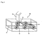
- Fig. 1 is a perspective view that schematically shows a cooling apparatus for a fired body in accordance with the first aspect of the present invention.
- a cooling apparatus 30 for a fired body is provided with a transporting member 31 for transporting a firing jig 33 in which a honeycomb fired body 36 is housed, a plurality of blowers 32 that are placed at both sides with respect to the transporting member 31, and used for cooling the honeycomb fired body 36, and a suction mechanism 34, placed at the upper side with respect to the transporting member 31, which changes the atmosphere inside the firing jig 33 from an inert gas atmosphere to an air atmosphere.
- a removing member 35 for removing deposits adhering to the firing jig 33 in a firing, is attached in a manner so as to enclose the firing jig 33 that has been transported.
- the transporting member 31 not particularly limited as long as it allows the firing jig 33 to be smoothly transported, and for example, a conveyor, such as a belt conveyor and a chain conveyor, a transporting device of a walking beam type and the like may be used.
- a conveyor such as a belt conveyor and a chain conveyor, a transporting device of a walking beam type and the like may be used.
- the honeycomb fired body 36 inside the firing jig 33 carried out from a firing furnace is transported by the transporting member 31 from a carrying-in port in its housed state inside the firing jig 33, and cooled by the blowers 32 placed at both sides with respect to the transporting member 31, and then carried out from a carrying-out port.
- the honeycomb fired body 36 is maintained in the housed state inside the firing jig 33, with the result that the honeycomb fired body 36 is not directly exposed to a cooling air flow from the blowers 32.
- the honeycomb fired body 36 is not locally cooled, it is possible to reduce a thermal impact or the like imposed on the honeycomb fired body 36, and consequently to prevent cracks and the like from occurring in the honeycomb fired body 36.
- the honeycomb fired body 36 is illustrated in an exposed state in the firing jig 33 shown in Fig. 1 ; however, a roof plate is normally mounted on the uppermost portion of the firing jig 33, and the honeycomb fired body 36 is housed in the firing jig 33 in a non-exposed state.
- the honeycomb fired body 36 is cooled, and in the case where the atmosphere inside the firing jig 33 is an inert gas atmosphere, this inert gas atmosphere can be changed into an air atmosphere.
- the brush or the like of the removing member 35 removes deposits adhering to the surface of the firing jig 33 through its reciprocating movements, rotation movements or the like.
- the deposits, thus removed by the removing member 35 are sucked by the suction mechanism 34 attached to a position closer to the carrying-out port than the position where the removing member 35 is installed, and collected outside the cooling apparatus 30 for a fired body together with the inert gas.
- the attached position of the removing member 35 is not particularly limited, as will be described later.
- the firing jig 33 from which the deposits have been removed is transported through a carrying-out port, and transported to the next process.
- the honeycomb fired body 36 since the honeycomb fired body 36 has been cooled to a temperature that is sufficiently low to allow the succeeding treatment or inspection, the honeycomb fired body 36 can be directly sent to the next process without the necessity of a waiting process; thus, it becomes possible to improve the working efficiency.
- the firing jig 33 which is used upon firing a honeycomb molded body (ceramic molded body), is a firing jig made from a ceramic material, which can be used in a superposed state with a number of stages.
- the firing jig 33 is provided with a vent portion at its one portion so as to allow ventilation between a space surrounded by the firing jig 33 and the outside, when superposed. Therefore, during the firing and the cooling, the firing igs 33, each housing a honeycomb molded body (ceramic molded body), are superposed in multiple stages, and firing is carried out thereon; thus, the resulting honeycomb fired body 36 can be cooled by the cooling apparatus 30 for a fired body.
- the blower 32 its structure is not particularly limited as long as a convection of an atmospheric gas is raised inside the firing jig 33, and a structure in which an air blow is formed by rotating blades at high speeds or a structure in which a pressure is applied to the atmospheric gas to form an air blow may be used.
- the blower 32 may send a cooling air flow having the same temperature as the temperature of the inside of the cooling apparatus 30 for a fired body, or a cooling air flow having a different temperature.
- the temperature of cooling air flows to be sent from the blowers 32 can be appropriately changed by taking into consideration the properties of the honeycomb firedbody 36, working efficiency and the like.
- the suction mechanism 34 is being operated during at least the time when cooling in which the honeycomb fired body 36 is cooled by operating the cooling apparatus 30 for a fired body is carried out, so that air, warmed up by the honeycomb fired body is continuously or regularly sucked. For this reason, it is possible to cool the honeycomb fired body quickly.
- the atmosphere inside the firing jig 33 can be changed into an air atmosphere.
- the atmosphere inside the firing furnace is normally substituted by an inert gas atmosphere so as to suppress undesired reactions upon firing the honeycomb molded body (ceramic molded body), and in addition to the substituted atmosphere inside the firing furnace, the inside of the firing jig 33 is of course substituted by an inert gas atmosphere.
- the inert gas atmosphere inside the firing jig 33 can be changed into an air atmosphere by operating the suction mechanism 34.
- the cooling apparatus 30 for a fired body is provided with an air intake (not shown) for taking in clean air from outside, and capable of continuously taking in clean air such as filtered air. Therefore, the inside of the cooling apparatus 30 for a fired body is maintained in an air atmosphere.
- the blowers are desirably placed at both sides with respect to the transporting member.
- the firing jig 33 can be cooled equally so that the honeycomb fired body 36 housed in the firing jig 33 can also be cooled uniformly.
- the numbers thereof may be the same or different from each other, as long as the honeycomb fired body 36 can be uniformly cooled.
- the installation intervals of the blowers 32 may be equal to or different from each other; however, from the viewpoint of a uniform cooling for the firing jig 33 (honeycomb fired body 36), the equal installation interval is more desirable.
- blowers at one of the sides and those at the other side may be placed face to face with each other, or may be placed alternately, as long as the honeycomb fired body 36 can be uniformly cooled. From the viewpoint of the cooling efficiency, those are desirably placed alternately.
- the suction mechanism is desirably placed at the upper side with respect to the transporting member.
- deposits, dusts and the like, removed by the removing member 35 are scattered by air directed from the blowers 32, this arrangement allows the deposits, dusts and the like to be properly sucked and externally discharged without again adhering to the transporting member 31 and the firing jig 33.
- air, sent from the blowers is heated due to heat obtained upon cooling the firing jig, and directed upward.
- the suction mechanism 34 When the suction mechanism is placed at the upper side with respect to the transporting member, the air that has been heated and directed upward can be efficiently sucked so that an inert gas, deposits, dusts and the like are efficiently sucked. In this manner, the suction mechanism 34 is also allowed to function as a dust collector.
- a suction pressure and shape of the suction mechanism 34 can be properly altered by taking into consideration the ventilation capability, installation spaces and the like required for exchanging atmospheric gases.
- a shape in which a suction port is formed only on one portion of the upper face of the cooling apparatus 30 for a fired body may be used, or a flange shape in which the entire upper face serves as a suction port, with the diameter of the suction port being gradually narrowed, may be used.
- the cooling apparatus for a fired body of the first aspect of the present invention is desirably provided with a removing member for removing deposits adhering to the firing jig, as indicated in the cooling apparatus 30 for a fired body shown in Fig. 1 .
- the honeycomb fired body ceramic fired body
- the removing member 35 is prepared, the deposits adhering to the firing jig 33 can be removed so that even when the firing jig 33 is used in the next firing, no adverse effects are given to the firing of the honeycomb molded body (ceramic molded body) so that the firing jig 33 can be used repeatedly without the necessity of carrying out the removing of the deposits separately. Therefore, the firing jig can be used repeatedly without the necessity of overlapped maintenance.
- the number of the removing members 35 is not particularly limited as
- the removing member not particularly limited as long as it can remove deposits adhering to the firing jig, a brush as shown in Fig. 1 may be used, or a curtain-shaped member may be used.
- the removing member is desirably designed to be made in contact with the upper face and side faces of the firing jig as shown in Fig. 1 ; however, it may be designed to be made in contact with only the upper face or only the side faces of the firing jig.
- the material for the removing member examples thereof include: resin, cloth and leather.
- the removing member may be prepared as a fixed member as shown in Fig. 1 , or may have a mode in which it is driven through vibration, reciprocating movement, rotating movement or the like to remove the deposits.
- the removing member 35 With respect to the installation position of the removing member 35, not particularly limited, it may be installed at a position closer to the carrying-in port than the position where the suction mechanism 34 is installed or, in contrast, may be installed at a position closer to the carrying-out port than the position where the suction mechanism 34 is installed. Moreover, it may be installed right below the suction mechanism 34. In either of the cases, the deposits can be efficiently removed by the removing member 35.
- the removing member is desirably attached to the vicinity of the suction mechanism. This arrangement allows the deposits removed by the removing member to be sucked without being scattered, making it possible to maintain the inside of the cooling apparatus for a fired body in a clean state.
- the cooling apparatus for a fired body of the first aspect is desirably ins tailed next to the carrying-out port of the firing furnace.
- the honeycomb fired body ceramic fired body
- Fig. 2 (a) is a cross-sectional view that shows a mode in which the cooling apparatus for a fired body of the first aspect of the present invention is installed next to the carrying-out port of the firing furnace. In the mode shown in Fig. 2 (a) , the cooling apparatus 30 for a fired body is installed next to a carrying-out port 10b of the firing furnace 10.
- the firing furnace 10 is a continuous furnace, and the honeycomb molded body, transported through a carrying-in port 10a, is fired in the furnace, and then carried out through the carrying-out port 10b as a honeycomb fired body.
- the honeycomb fired body, thus transported through the carrying-out port 10b, is then successively transported into the cooling apparatus 30 for a fired body where it is cooled by the blowers 32 as described earlier.
- the mode shown in Fig. in the mode shown in Fig.
- a continuous single transporting member 31 is used as a transporting member for transporting the honeycomb fired body through the cooling apparatus 30 for a fired body and as a transporting member for transporting the honeycomb molded body through the firing furnace 10; however, in this case, the transporting member is not necessarily prepared as the continuous single transporting member, and another structure may be used in which respectively different transporting members are used in the firing furnace and in the cooling apparatus for a fired body so that after the carrying-out from the firing furnace is carried out, the transporting members are switched to support the firing jig 33 before the carrying-in to the cooling apparatus for a fired body.
- the firing furnace next to which the cooling apparatus for a fired body is installed is not limited to a continuous furnace as shown in Fig. 2 (a) , and may be prepared as a batch furnace.
- Fig. 2 (b) is a cross-sectional view that shows the firing furnace in which the cooling apparatus for a fired body of the first aspect of the present invention is installed.
- the honeycomb fired body ceramic fired body
- the cooling apparatus for a fired body is provided with the suction mechanism, since an inert gas atmosphere can be changed into an air atmosphere, the cooling apparatus for a fired body is allowed to function as both of a cooling unit and a degassing unit in the conventional firing furnace, thereby making it possible to save the space in the firing furnace and consequently to provide a further efficient method.
- a degassing unit 21 As shown in Fig. 2(b) , from the carrying-in port 20a to the carrying-out port 20b inside the firing furnace 20, a degassing unit 21, a pre-heating unit 22, a heating unit 23, an cooling-down unit 24 and the cooling apparatus 40 for a fired body are successively installed.
- the structure of the cooling apparatus 40 for a fired body is the same as described earlier; therefore, the description thereof is omitted.
- the heating unit 23 has a structure in which a cylinder-shapedmuffle 11 is formed so as to ensure a space through which the firing jig 33 housing the molded body therein passes.
- heaters 12 are installed above and below the muffle 11 with predetermined intervals, and a heat-insulating layer 13 is formed in a manner so as to surround the muffle 11 and the heater 12.
- a heat-insulating layer attaching member 16 for attaching the heat-insulating layer 13 is placed outside the heat-insulating layer 13, and a furnace-cooling member (water-cooling jacket) 14 is installed outside the heat-insulating layer attaching member 16, that is, on the outermost surface of the firing furnace 20.
- the atmosphere inside the firing furnace 20 (inside of the pre-heating unit 22, the heating unit 23 and the cooling-down unit 24) is exchanged by an inert gas atmosphere by an inert gas 17 introduced from the outside, and isolated from the ambient atmosphere by the furnace cooling member 14.
- a cooling fluid such as water, is allowed to flow the inside of the cooling furnace member 14 so that the cooling furnace member 14 is maintained at a predetermined temperature.
- the atmosphere of the inside of the firing furnace 20 may be set to a predetermined atmosphere depending on the kind of a ceramic molded body.
- the heaters 12 are installed above and below the muffle 11; however, the installation position of the heaters is not limited to this, and the heaters 12 may be installed at any place as long as they are on the peripheral portion of the muffle 11.
- the entire floor portion of the muffle 11 is supported by a supporting member, not shown, and the firing jig 33 housing the honeycomb molded body (ceramic molded body) therein is allowed to pass through it.
- the muffle 11 is placed over the entire portion of the firing furnace 20 except for the degassing unit 21 and the cooling apparatus 40 for a fired body.
- Each heater 12 is a heat generating member made of graphite or the like, and the heater 12 is connected to a power supply (not shown) located outside through a terminal 18.
- the heaters 12 are installed in the heating unit 23, and are also installed in the pre-heating unit 22, if necessary.
- the heat-insulating layers 13, which block heat generated from the heating unit 23 and heat transmitted from the heating unit 23, are placed on the pre-heating unit 22, the heating unit 23 and the cooling-down unit 24.
- the heat-insulating layer 13 is placed so as to surround the heater 12, and the heat-insulating layer 13 is attached and secured to the heat-insulating layer attaching member 16 installed right outside thereof.
- the cooling furnace member 14 is placed over the entire area except for the degassing unit 21 on the outermost side.
- the degassing unit 21 is installed so as to change the atmosphere of the inside and peripheral portion of the firing jig 43 to be carried in into an inert gas atmosphere for use in firing. With respect to the sequence of processes for exchanging the atmosphere in the degassing unit 21, after the firing jig 33 mounted on the supporting base has been carried in, the degassing unit 21 is once evacuated, and an inert gas is then directed thereto so that the atmosphere of the inside and periphery of the firing jig 43 is changed into an inert gas atmosphere.
- the pre-heating unit 22 gradually raises the temperature of the firing jig 33 in which the honeycomb molded body (ceramic molded body) is housed by using the attached heaters, or by utilizing the heat of the heating unit.
- the firing jig 33 is transported to the heating unit 23 by the transporting means 19, and firing is carried out on the honeycomb molded body in the heating unit 23.
- the firing jig 43 after the firing is gradually cooled in the cooling-down unit 24.
- the firing jig 43 is transported to the cooling apparatus 40 for a fired body installed inside the firing furnace 20 so that the temperature of the firing jig 43 is lowered to a predetermined temperature by using a plurality of blowers 32 installed in the cooling apparatus 40 for a fired body.
- the cooling apparatus 40 for a fired body while the firing jig 43 is cooled to the predetermined temperature, deposits adhering to the firing jig 43 are removed by a removing member 35 installed on demand, and the atmosphere inside the firing jig 43 is exchanged from an inert gas atmosphere to an air atmosphere by using a suction mechanism (not shown) attached at the upper side with respect to the transporting means or the transporting member, and the firing jig 43 is carried out through the carrying-out port 20b; thus, the firing are completed.
- the cooling apparatus 40 for a fired body is disposed such that a distance between the cooling apparatus 40 for a fired body and the carrying-out port is smaller than a distance between the heating unit 23 and the carrying-out port.
- the cooling apparatus 40 for a fired body is placed at any position as long as it is located at least behind the heating unit 23, when viewed in the transporting direction of the transporting means 19.
- the atmosphere inside the firing jig 43 can be exchanged to an air atmosphere without the necessity of separately installing a degassing unit or the like in the firing furnace 20.
- a transporting means 19 forming the firing furnace 20 may be extended into the cooling apparatus 40 for a fired body so that the firing jig 33 is transported, or the transporting member 31 and the transporting means 19 may be combined so as to carry out the transporting.
- the firing furnace of this kind in which the cooling apparatus for a fired body is installed is also one aspect (firing furnace of the second aspect of the present invention) of the present invention.
- the firing furnace of the second aspect of the present invention since no transporting of a honeycomb fired body (ceramic fired body) is separately prepared between the firing and the cooling of the honeycomb fired body (ceramic fired body), the firing and cooling can be continuously carried out so that the all the processes including the firing and the cooling can be efficiently carried out.
- a ceramic fired body housed in a firing jig, is cooled by using a cooling apparatus provided with a plurality of blowers.
- the cooling apparatus to be used in the cooling method of a ceramic f iredbody of the third aspect of the present invention is only required to include a transporting member and a plurality of blowers, and its structure is not particularly limited. With respect to the transporting member and the blowers, those transporting member and blowers used in the cooling apparatus for a fired body of the first aspect of the present invention are desirably used. With respect to the cooling apparatus having such a structure, more specifically, a structure in which no suction mechanism is attached to the cooling apparatus for a fired body in accordance with the first aspect of the present invention that has been explained by reference to Fig. 1 is proposed. Of course, the cooling apparatus to be used in the cooling method of the third aspect of the present invention may be provided with a suction mechanism.
- the honeycomb fired body (ceramic fired body) is desirably cooled to 20 to 80°C in 30 to 120 minutes.
- the temperature of the honeycomb fired body (ceramic fired body) that has been fired and transported through the cooling-down unit is about 280 to 300°C, and the cooling is carried out from this temperature range, under predetermined cooling conditions.
- the honeycomb fired body (ceramic fired body) fails to withstand a thermal impact caused upon cooling, resulting in damages such as cracks; in contrast, in the case where the cooling time required to cool to 80°C exceeds 120 minutes, it is considered that this operation is not effective from the viewpoint of improving the cooling efficiency.
- the flow rate from the blowers installed in the cooling apparatus may be appropriately changed in accordance with the number of honeycomb fired bodies (ceramic fired bodies) to be cooled and the shape and the like of the firing jig, and, for example, the flow rate range from 10000 to 40000 m 3 /h can be adopted. With this flow rate range, it becomes possible to carry out an efficient cooling operation while preventing the occurrence of cracks or the like in the honeycomb fired body (ceramic fired body).
- the temperature inside the cooling apparatus is desirably set in a range from 15 to 30°C. With this temperature range, it becomes possible to carry out an efficient cooling operation while preventing the occurrence of cracks or the like in the honeycomb fired body (ceramic fired body).
- the cooling apparatus to be used in the third aspect of the present invention is desirably provided with a suction mechanism for sucking the internal area of the cooling apparatus.
- the cooling apparatus for a fired body in accordance with the first aspect of the present invention is desirably adopted.
- blowers are desirably placed at both sides with respect to the transporting member, and the cooling apparatus is also desirably provided with a removing member for removing deposits adhering to the firing jig.
- a removing member for removing deposits adhering to the firing jig.
- the suction speed during the sucking by the suction mechanism is desirably set to 5 to 10 m/s inside the pipe.
- the suction speed is set in the above-mentioned range, it is possible to efficiently exchange the atmosphere inside the firing jig and to effectively suck the exchanged inert gas and deposits.
- the firing jig used in the cooling apparatus for a fired body of the first aspect of the present invention is desirably used.
- the number of stages of the superposed firing jigs not particularly limited, one stage or a multiple superposed stages may be used. In particular, when 5 to 15 superposed stages are used, it becomes possible to improve the processing efficiency by using the multiple superposed stages, while preventing the cooling of the honeycomb fired body (ceramic fired body) from becoming insufficient.
- the number of honeycomb fired bodies (ceramic fired bodies) to be housed in one firing jig is desirably set to 7 to 20, when the cooling efficiency is taken into consideration.
- a method for manufacturing a honeycomb structured body in accordance with a fourth aspect of the present invention is a method for manufacturing a honeycomb structured body, comprising: manufacturing a pillar-shaped honeycomb molded body having a large number of cells longitudinally placed in parallel with one another with a cell wall therebetween, by molding a ceramic raw material; firing the honeycomb molded body in a firing jig to manufacture a honeycomb structured body comprising a honeycombfiredbody, andfurthercomprising:preparingacooling apparatus comprising a transporting member for transporting the firing jig; and a plurality of blowers; and cooling the honeycomb fired body by using the cooling apparatus after the firing of the honeycomb molded body inside the firing jig.
- the shape indicated by the word "pillar” refers to any desired shape of a pillar including a round pillar, an oval pillar, a polygonal
- Fig. 3 is a perspective view that schematically shows one example of a honeycomb structured body in accordance with the present invention.
- Fig. 4(a) is a perspective view that schematically shows a honeycomb fired body forming the honeycomb structured body in accordance with the present invention.
- Fig. 4(b) is a cross-sectional view taken along line A-A.
- honeycomb fired bodies 140 shown in Figs. 4 (a) and 4 (b) are bound to one another by interposing sealing material layers (adhesive layers) 131 to form a honeycomb block 133, and a sealing material layer (coat layer) 132 is further formed on the periphery of this honeycomb block 133.
- the honeycomb fired body 140 has a large number of cells 141 longitudinally placed in parallel with one another, and each cell wall 143 that separates the cells 141 is allowed to function as a filter.
- each of the cells 141 formed in the honeycomb fired body 140, is sealed with a plug material layer 142 at either one of ends on its exhaust gas inlet side and exhaust gas outlet side, so that exhaust gases that have entered one cell 141 are discharged from another cell 141 after having always passed through each cell wall 143 that separates the cells 141.
- exhaust gases pass through the cell wall 143, particulates are captured by the cell wall 143, so that the exhaust gases are purified.
- the following description will discuss the method for manufacturing a honeycomb structured body in which powder of silicon carbide that is a ceramic raw material is used, by exemplifying manufacturing of a honeycomb structured body which is mainly composed of silicon carbide as a constituent material.
- the main component of constituent materials for the honeycomb structured body is not intended to be limited by silicon carbide, and, other examples thereof include: nitride ceramic materials, such as aluminum nitride, silicon nitride, boron nitride and titanium nitride, carbide ceramic materials, such as zirconium carbide, titanium carbide, tantalum carbide and tungsten carbide, oxide ceramic materials, such as alumina, zirconia, cordierite, mullite, and aluminum titanate, and the like.
- non-oxide ceramic materials are desirably used, and in particular, silicon carbide is more desirably used.
- Silicon carbide is used because of its superior heat resistant property, mechanical strength, thermal conductivity and the like.
- materials such as a silicon-containing ceramic material formed by blending metal silicon in the above-mentioned ceramic material and a ceramic material that is combined by silicon or a silicate compound, may also be used as the constituent materials, and among these, a material in which metal silicon is blended in silicon carbide (silicon-containing silicon carbide) is desirably used.
- inorganic powder such as silicon carbide powders having different average particle diameters, and an organic binder are dry-mixed to prepare mixed powder, and a liquid-state plasticizer, a lubricant and water are mixed to prepare a mixed liquid, and the mixed powder and the mixed liquid are mixed by using a wet-mixing device so that a wet mixture for use in manufacturing a molded body is prepared.
- particle diameter of silicon carbide powder although not particularly limited, those which are less susceptible to shrinkage in the succeeding firing are desirably used, and for example, mixed powder, prepared by combining 100 parts by weight of powder having an average particle diameter from 0.3 to 50 ⁇ m with 5 to 65 parts by weight of powder having an average particle diameter from 0.1 to 1.0 ⁇ m, is desirably used.
- mixed powder prepared by combining 100 parts by weight of powder having an average particle diameter from 0.3 to 50 ⁇ m with 5 to 65 parts by weight of powder having an average particle diameter from 0.1 to 1.0 ⁇ m.
- the firing temperature it is necessary to adjust the firing temperature, and the pore diameter can be adjusted by adjusting the particle diameter of the inorganic powder.
- organic binder examples thereof include: methylcellulose, carboxy methylcellulose, hydroxy ethylcellulose, polyethylene glycol and the like. Among these, methylcellulose is more desirably used.
- the compounding amount of the above-mentioned binder is desirably set to 1 to 10 parts by weight with respect to 100 parts by weight of the inorganic powder.
- plasticizer not particularly limited, for example, glycerin and the like may be used.
- lubricant not particularly limited, for example, polyoxy alkylene-based compounds, such as polyoxyethylene alkyl ether and polyoxy propylene alkyl ether and the like may be used.
- specific examples of the lubricant include: polyoxyethylene monobutyl ether and polyoxypropylene monobutyl ether.
- the plasticizer and the lubricant are not necessarily contained in the mixed material powder depending on cases.
- a dispersant solution may be used, and with respect to the dispersant solution, examples thereof include: water, alcohol such as methanol, an organic solvent such as benzene, and the like.
- a molding auxiliary may be added to the wet mixture. With respect to the molding auxiliary, not particularly limited, examples thereof include: ethylene glycol, dextrin, fatty acid, fatty acid soap, polyalcohol and the like.
- a pore forming agent such as balloons that are fine hollow spheres composed of oxide-based ceramics, spherical acrylic particles, graphite and the like may be added to the above-mentioned wet mixture, if necessary.
- balloons not particularly limited, for example, alumina balloons, glass micro-balloons, shirasu balloons, fly ash balloons (FA balloons), mullite balloons and the like may be used.
- alumina balloons are more desirably used.
- the temperature thereof is desirably set to 28°C or less.
- the organic binder tends to be gelatinized.
- the rate of organic components in the wet mixture is desirably set to 10% by weight or less, and the content of moisture is desirably set from 8.0 to 20.0% by weight or less.
- Thewetmixture, thus prepared, is transported, and charged into a molding machine.
- the wet mixture transported by the transporting device and charged into the molding machine is then extrusion-molded into a honeycomb molded body having a predetermined shape.
- the resulting honeycomb molded body is dried by using a drying apparatus, such as a microwave drying apparatus, a hot-air drying apparatus, a dielectric drying apparatus, a reduced-pressure drying apparatus, a vacuum drying apparatus, a frozen drying apparatus and the like so that a dried honeycomb molded body is formed.
- cutting is carried out on the honeycomb molded body thus formed, by using a cutting machine to cut the two ends thereof so that a honeycomb molded body having a predetermined length is formed.
- a predetermined amount of plug material paste that forms plugs is filled into ends on the outlet side of a group of cells on the inlet side and ends on the inlet side of a group of cells on the outlet side, if necessary, so that predetermined cells are sealed.
- a mask for sealing the cells is made in contact with the end face (that is, the cut face after the cutting) of the honeycomb molded body so that only the cells to be sealed are filled with the plug material paste.
- plug material paste although not particularly limited, those plug material pastes that allow the plugs manufactured through post processes to have a porosity in a range from 30 to 75% are desirably used, and, for example, the same material as that of the wet mixture may be used.
- the filling of the plug material paste can be carried out on demand, and when the plug material paste has been filled thereto, for example, the resulting honeycomb structured body obtained through the post process is desirably used as a honeycomb filter, and in the case where no plug material paste has been filled thereto, for example, the honeycomb structured body obtained through the post process is desirably used as a catalyst supporting body.
- the honeycomb molded body which has the plug material paste filled therein, is transported to a degreasing furnace by using a degreasing furnace carrying-in device so as to be degreased.
- the honeycomb molded body is carried in into the degreasing furnace by using the degreasing furnace carrying-in device face, and degreased under predetermined conditions (for example, 200 to 500°C).
- the honeycomb molded body on which degreasing has been carried out is fired in a firing jig, and the resulting honeycomb fired body is cooled by using a cooling apparatus in which a transporting member for transporting the firing jig and a plurality of blowers so that it is possible to manufacture a honeycomb fired body (see Figs. 4(a) and 4(b) ) formed by a single fired body as a whole in which: a plurality of cells are longitudinally placed in parallel with one another with a cell wall therebetween, and either one of ends of the cells is sealed.
- the honeycomb molded body is housed in a firing jig, and firing thereof is carried out in this state.
- the firing jig explained in the cooling apparatus for a fired body of the first aspect of the present invention, is desirably used.
- the firing conditions for the honeycomb molded body those conditions conventionally used upon manufacturing a filter made from a porous ceramic material (for example, 1400 to 2300°C for 1 to 10 hours) may be used.
- the resulting honeycomb fired body is cooled in a fired body cooling in which a cooling apparatus provided with a transporting member for transporting the firing jig and a plurality of blowers is used.
- a cooling apparatus provided with a transporting member for transporting the firing jig and a plurality of blowers is used.
- the cooling method explained in the cooling method for the ceramic fired body of the third aspect of the present invention, is desirably used.
- the cooling desirably cools ceramic fired body 20 to 80°C in 30 to 120 minutes.
- the cooling apparatus is desirably provided with a suction mechanism for sucking the internal area of the cooling apparatus, the plurality of blowers are desirably placed at both sides with respect to the transporting member, and the suction mechanism is desirably placed at the upper side with respect to the transporting member.
- the cooling apparatus is desirably provided with a removing member for removing deposits adhering to the firing jig.
- a sealing material paste to form a sealing material layer (adhesive layer) is applied onto side faces of the honeycomb fired body thus cooled with an even thickness to form a sealing material paste layer, and laminating for forming another honeycomb fired body on this sealing material paste layer is successively repeated so that an aggregate of honeycomb fired bodies having a predetermined size is manufactured.
- examples thereof include an inorganic binder, an organic binder and a material made from inorganic fibers and/or inorganic particles.
- the inorganic binder for example, silica sol, alumina sol and the like may be used. Each of these may be used alone or two or more kinds of these may be used in combination.
- silica sol is more desirably used.
- organic binder examples thereof include polyvinyl alcohol, methyl cellulose, ethyl cellulose, carboxymethyl cellulose, and the like. Each of these may be used alone or two or more kinds of these may be used in combination. Among the organic binders, carboxymethyl cellulose is more desirably used.
- examples thereof include ceramic fibers, such as silica-alumina, mullite, alumina, silica, and the like. Each of these may be used alone or two or more kinds of these may be used in combination.
- alumina fibers are more desirably used.
- examples thereof include carbides and nitrides, and specific examples include inorganic powder or the like made from silicon carbide, silicon nitride and boron nitride. Each of these may be used alone, or two or more kinds of these may be used in combination.
- silicon carbide having superior thermal conductivity is desirably used.
- a pore forming agent such as balloons that are fine hollow spheres composed of oxide-based ceramics, spherical acrylic particles, graphite and the like may be added to the above-mentioned sealing material paste, if necessary.
- balloons not particularly limited, for example, alumina balloons, glass micro-balloons, shirasuballoons, flyashballoons (FAballoons), mullite balloons and the like may be used.
- alumina balloons are more desirably used.
- this aggregate of honeycomb fired bodies is heated so that the sealing material paste layers are dried and solidified to form sealing material layers (adhesive layers).
- cutting is carried out on the aggregate of honeycomb fired bodies in which a plurality of honeycomb fired bodies have been bonded to one another by interposing sealing material layers (adhesive layers), by using a diamond cutter or the like so that a cylindrical honeycomb block is manufactured.
- a sealing material layer is formed on the peripheral portion of the honeycomb block by using the above-mentioned sealing material paste so that a honeycomb structured body in which a sealing material layer (coat layer) is formed on the periphery of a cylindrical honeycomb block having a structure in which a plurality of honeycomb fired bodies are bound to one another by interposing sealing material layers (adhesive layers) is manufactured.
- a catalyst is supported on the honeycomb structured body on demand.
- the supporting of the catalyst may be carried out on the honeycomb fired bodies prior to being formed into an aggregate.
- an alumina film having a high specific surface area is desirably formed on the surface of the honeycomb structured body, and a co-catalyst and a catalyst such as platinum are applied onto the surface of the alumina film.
- the method for forming the alumina film on the surface of the honeycomb structured body for example, a method in which the honeycomb structured body is impregnated with a solution of a metal compound containing aluminum such as Al (NO 3 ) and then heated and a method in which the honeycomb structured body is impregnated with a solution containing alumina powder and then heated, are proposed.
- a method for applying a co-catalyst to the alumina film for example, a method in which the honeycomb structured body is impregnated with a solution of a metal compound containing a rare-earth element, such as Ce (NO 3 ) 3 , and then heated is proposed.
- a method for applying a catalyst to the alumina film for example, a method in which the honeycomb structured body is impregnated with a solution of diammine dinitro platinum nitric acid ([Pt(NH 3 ) 2 (NO 2 ) 2 ]HNO 3 , platinum concentration: 4.53% by weight) and then heated is proposed.
- a catalyst may be applied through a method in which after the catalyst has been preliminarily applied to alumina particles, the honeycomb structured body is impregnated with a solution containing the alumina powder bearing the catalyst applied thereto, and then heated.
- the above-mentioned method for manufacturing a honeycomb structured body relates to an aggregated honeycomb structured body having a structure in which a plurality of honeycomb fired bodies are bound to one another by interposing sealing material layers (adhesive layers); however, the honeycomb structured body to be manufactured by the method of the present invention may be an integral honeycomb structured body in which a pillar-shaped honeycomb block is constituted by one honeycomb fired body.
- the integral honeycomb structured body is mainly composed of a material such as cordierite and aluminum titanate.
- a honeycomb molded body of this kind is formed by using the same method as the method for manufacturing an aggregated honeycomb structured body except that the size of a honeycomb molded body to be molded through the extrusion-molding is greater than that of the aggregated honeycomb structured body.
- the honeycomb molded body is dried by using a drying apparatus, such as a microwave drying apparatus, a hot-air drying apparatus, a dielectric drying apparatus, a reduced-pressure drying apparatus, a vacuum drying apparatus, a frozen drying apparatus and the like.
- a drying apparatus such as a microwave drying apparatus, a hot-air drying apparatus, a dielectric drying apparatus, a reduced-pressure drying apparatus, a vacuum drying apparatus, a frozen drying apparatus and the like.
- cutting is carried out on the dried honeycomb molded body, by using a cutting machine to cut the two ends thereof.
- a predetermined amount of plug material paste that forms plugs is filled into ends on the outlet side of a group of cells on the inlet side and ends on the inlet side of a group of cells on the outlet side so that predetermined cells are sealed.
- the degreasing and firing are carried out to manufacture a honeycomb block, and by forming a sealingmaterial layer (coat layer), if necessary, an integral honeycomb structured body can be manufactured.
- a catalyst may also be supported on the integral honeycomb structured body by using the same method.
- honeycomb structured body With respect to the honeycomb structured body, the foregoing explanation has been given mainly on a honeycomb filter that is used to collect particulates in exhaust gases; however, the honeycomb structured body may also be desirably used as a catalyst supporting body (honeycomb catalyst) that converts exhaust gases.
- honeycomb catalyst a catalyst supporting body
- the method for manufacturing a honeycomb structured body of the fourth aspect of the present invention as explained above, it is possible to manufacture a honeycomb structured body by using highly efficient operations. Moreover, upon manufacturing a honeycomb structured body through the above-mentioned method, since the cooling of the honeycomb fired body, which has been conventionally carried out through natural radiation, is carried out by using a predetermined cooling apparatus, a sequence of working can be carried out continuously in a more effective manner. Therefore, the method for manufacturing a honeycomb structured body in the fourth aspect of the present invention can also improve the efficiency of the all manufacturing method.
- a method for manufacturing a honeycomb structured body in accordance with a fifth aspect of the present invention is a method for manufacturing a honeycomb structured body comprising: manufacturing a pillar-shapedhoneycombmoldedbody having a large number of cells longitudinally placed in parallel with one another with a cell wall therebetween, by molding a ceramic rawmaterial; firing the honeycomb molded body in a firing jig by using a firing furnace to manufacture a honeycomb structured body comprising a honeycomb fired body; and further comprising: preparing a firing furnace comprises a cooling apparatus comprising a transporting member for transporting the firing jig; and a plurality of blowers; and firing the honeycomb molded body in the firing jig to manufacture the honeycomb fired body; and cooling of the honeycomb fired body, the firing and the cooling carried out in the firing furnace.
- the same method as the method for manufacturing a honeycomb structured body in accordance with the fourth aspect of the present invention can be used except for the firing and the cooling; therefore, with respect to the method for manufacturing a honeycomb structured body of the fifth aspect of the present invention, the following description will mainly discuss the firing and the cooling.
- a honeycomb molded body in which either one of ends of the cells is sealed with a plug material paste on demand is formed by using the same method as the method for manufacturing a honeycomb structured body of the fourth aspect of the present invention, and degreasing is carried out on the honeycomb molded body.
- a firing in which the honeycomb molded body is fired in the firing jig by using the firing furnace in which the transporting member for transporting the firing jig and the plurality of blowers are installed to form a honeycomb fired body and the cooling in which the honeycomb fired body is cooled are carried out. More specifically, the above-mentioned firing and cooling are desirably carried out by using the firing furnace in accordance with the second aspect of the present invention.
- the cooling desirably cools ceramic fired body 20 to 80°C in 30 to 120 minutes .
- the reasons for the above-mentioned arrangements to be desirably used have been explained in the cooling method of a ceramic fired body in accordance with the third aspect of the present invention; therefore, the description thereof is omitted.
- the cooling apparatus is desirably provided with a suction mechanism for sucking the internal area of cooling apparatus, the plurality of blowers are desirably placed at both sides with respect to the transporting member, and the suction mechanism is desirably placed at the upper side with respect to the transporting member.
- the cooling apparatus is desirably provided with a removing member for removing deposits adhering to the firing jig.
- honeycomb structured body After the honeycomb molded body has been fired and formed into a honeycomb fired body cooled to a predetermined temperature, an aggregate of the honeycomb fired bodies is formed and a honeycomb block is then manufactured by using the same manufacturing method as the honeycomb structured body of the fourth aspect of the present invention so that a honeycomb structured body is manufactured by further forming a sealing material layer (coat layer) thereon.
- a catalyst may be supported on a honeycomb structured body, if necessary, in the same manner as the method for manufacturing the honeycomb structured body in accordance with the fourth aspect of the present invention.
- an integral honeycomb molded body is formed by using the same method as method for manufacturing the honeycomb structured body of the fourth aspect of the present invention, that is, the method for manufacturing an aggregated honeycomb structured body, except that the size of a honeycomb molded body to be molded through extrusion-molding is greater than that of the aggregated honeycomb structured body.
- honeycomb structured body With respect to the honeycomb structured body, the foregoing explanation has been given mainly on a honeycomb filter that is used to collect particulates in exhaust gases; however, the honeycomb structured body may also be desirably used as a catalyst supporting body (honeycomb catalyst) that converts exhaust gases.
- honeycomb catalyst a catalyst supporting body
- the method for manufacturing a honeycomb structured body of the fifth aspect of the present invention as explained above, it is possible to manufacture a honeycomb structured body by using highly efficient operations. Moreover, upon manufacturing a honeycomb structured body through the above-mentioned method, since the firing and the cooling are carried out in the single firing furnace, a sequence of working can be carried out continuously in a more effective manner. Therefore, the method for manufacturing a honeycomb structured body in the fifth aspect of the present invention can also improve the efficiency of the entire manufacturing method.
- the present invention will be explained hereinafter in detail. However, the present invention is not limited only by these examples.
- the honeycomb fired bodies upon manufacturing honeycomb fired bodies, the honeycomb fired bodies were cooled under various cooling conditions so that the time required for cooling and changes in the honeycomb fired body after the cooling were examined.
- Powder of ⁇ -type silicon carbide having an average particle diameter of 10 ⁇ m (250 kg), powder of ⁇ -type silicon carbide having an average particle diameter of 0.5 ⁇ m (100 kg) and an organic binder (methylcellulose) (20 kg) were mixed to prepare mixed powder.
- a lubricant Uniloop, made by NOF Corporation (12 kg), a plasticizer (glycerin) (5 kg) and water (65 kg) were mixed to prepare a liquid mixture, and this liquid mixture and the mixed powder were mixed by using a wet-type mixing machine so that a wet mixture was prepared.
- the moisture content of the wet mixture thus prepared was 14% by weight.
- this wet mixture was transported to an extrusion molding machine by using a transporting device, and charged into a material charging port of the extrusion molding machine.
- the moisture content of the wet mixture immediately before the charging into the extrusion molding machine was 13.5% by weight.
- the wet mixture was then extrusion-molded into a rawmolded body having a shape shown in Figs. 4 (a) and 4 (b) , and not having its end portions sealed.
- a plug material paste having the same composition as the wet mixture was filled into predetermined cells.
- the honeycomb molded body to which the plug material paste had been filled was again dried by using a drying apparatus, and the honeycomb molded body thus dried was carried in a degreasing furnace.
- the honeycomb molded body, carried in the degreasing furnace, was degreased at 400°C.
- the honeycomb molded body, mounted on the firing jig was put into a continuous firing furnace where it was fired at 2200°C in a normal-pressure argon atmosphere serving as an inactive gas for 3 hours.
- a cooling apparatus 30 for a fired body having a structure shown in Fig. 1 was placed next to the carrying-out port of the continuous firing furnace, and cooling was carried out on the honeycomb fired body under conditions as shown in Table 1.
- the honeycomb fired body which was a silicon carbide sintered body, had a porosity of 40%, an average pore diameter of 12.5 ⁇ m, a size of 34.3 mm x 34.3 mm x 150 mm, the number of cells (cell density) of 46.5/cm 2 and a thickness of each cell wall of 0.20 mm.
- Example 2 The same processes as Example 1 were carried out except that the cooling conditions in the cooling process were set to values shown in Table 1 to manufacture a honeycomb fired body.
- Example 2 The same processes as Example 1 were carried out except that the cooling conditions in the cooling process were set to values shown in Table 1 to carry out a swift cooling treatment so that a honeycomb fired body was manufactured.
- Example 2 The same processes as Example 1 were carried out except that the cooling process was carried out through natural radiation, without carrying out the cooling process by the cooling apparatus for a fired body.
- JIS R 1601 four-points bending tests were carried out under conditions of an upper-face span-to-span distance of 20 mm, a lower-face span-to-span distance of 133 mm, a speed of 10 mm/min and an applied load of 2940 N(300 kgf) by using an Instron 5582 so that the honeycomb fired body was observed as to whether or not there were any damages.
- the number of the test pieces was set to ten.
- the results are as shown in Table 1.
- the applied load is an experience value of which a normal honeycomb fired body is not destroyed but a honeycomb fired body having defects such as cracks and the like is destroyed.
- the honeycomb fired body can be cooled to 30 to 40°C in 40 to 100 minutes and the cooled honeycomb fired body was not broken even under the breaking test; thus, it can be said that an efficient cooling was carried out under the cooling conditions in Examples 1 to 5.
Landscapes
- Engineering & Computer Science (AREA)
- Mechanical Engineering (AREA)
- General Engineering & Computer Science (AREA)
- Tunnel Furnaces (AREA)
- Furnace Details (AREA)
Priority Applications (1)
| Application Number | Priority Date | Filing Date | Title |
|---|---|---|---|
| PL07002322T PL1832827T3 (pl) | 2006-03-08 | 2007-02-02 | Urządzenie chłodzące wypalanego korpusu, piec do wypalania, sposób chłodzenia wypalanego korpusu ceramicznego oraz sposób wytwarzania korpusu o strukturze plastra miodu |
Applications Claiming Priority (1)
| Application Number | Priority Date | Filing Date | Title |
|---|---|---|---|
| PCT/JP2006/304510 WO2007102217A1 (ja) | 2006-03-08 | 2006-03-08 | 焼成体用冷却機、焼成炉、セラミック焼成体の冷却方法、及び、ハニカム構造体の製造方法 |
Publications (2)
| Publication Number | Publication Date |
|---|---|
| EP1832827A1 EP1832827A1 (en) | 2007-09-12 |
| EP1832827B1 true EP1832827B1 (en) | 2008-08-20 |
Family
ID=37873226
Family Applications (1)
| Application Number | Title | Priority Date | Filing Date |
|---|---|---|---|
| EP07002322A Active EP1832827B1 (en) | 2006-03-08 | 2007-02-02 | Cooling apparatus for fired body, firing furnace, cooling method of ceramic fired body, and method for manufacturing honeycomb structured body |
Country Status (5)
| Country | Link |
|---|---|
| US (1) | US20080136053A1 (pl) |
| EP (1) | EP1832827B1 (pl) |
| DE (1) | DE602007000080D1 (pl) |
| PL (1) | PL1832827T3 (pl) |
| WO (1) | WO2007102217A1 (pl) |
Families Citing this family (59)
| Publication number | Priority date | Publication date | Assignee | Title |
|---|---|---|---|---|
| DE60041464D1 (de) * | 1999-09-29 | 2009-03-12 | Ibiden Co Ltd | Wabenförmiger Filter und Anordnung von keramischen Filtern |
| DE60319756T3 (de) | 2002-02-05 | 2014-04-17 | Ibiden Co., Ltd. | Wabenkörperfilter zur Abgasreinigung, Kleber, Beschichtungsmaterial und Verfahren zur Herstellung eines solchen Wabenfilterkörpers |
| DE60317174T3 (de) | 2002-03-22 | 2013-01-17 | Ibiden Co., Ltd. | Herstellungsverfahren eines wabenfilters zur reinigung von abgas |
| WO2003093657A1 (fr) | 2002-04-10 | 2003-11-13 | Ibiden Co., Ltd. | Filtre a alveoles servant a clarifier un gaz d'echappement |
| ES2295617T3 (es) * | 2002-04-11 | 2008-04-16 | Ibiden Co., Ltd. | Filtro de nido de abejas para clarificar gas de escape. |
| US20060051556A1 (en) * | 2003-09-12 | 2006-03-09 | Ibiden Co., Ltd. | Sintered ceramic compact and ceramic filter |
| JP4849891B2 (ja) * | 2003-11-05 | 2012-01-11 | イビデン株式会社 | ハニカム構造体の製造方法 |
| KR100804933B1 (ko) * | 2004-05-06 | 2008-02-20 | 이비덴 가부시키가이샤 | 벌집형 구조체 및 그 제조 방법 |
| EP1930058A3 (en) * | 2004-05-18 | 2008-07-30 | Ibiden Co., Ltd. | Honeycomb structural body and exhaust gas purifying device |
| EP1647790B1 (en) * | 2004-07-01 | 2008-08-20 | Ibiden Co., Ltd. | Method of manufacturing porous ceramic body |
| CN1969163B (zh) * | 2004-08-04 | 2010-09-29 | 揖斐电株式会社 | 烧制炉及使用该烧制炉制造多孔陶瓷部件的方法 |
| DE602005019182D1 (de) * | 2004-09-30 | 2010-03-18 | Ibiden Co Ltd | Wabenstruktur |
| DE602005015610D1 (de) * | 2004-10-12 | 2009-09-03 | Ibiden Co Ltd | Keramische wabenstruktur |
| WO2006082938A1 (ja) * | 2005-02-04 | 2006-08-10 | Ibiden Co., Ltd. | セラミックハニカム構造体およびその製造方法 |
| JP2006223983A (ja) * | 2005-02-17 | 2006-08-31 | Ibiden Co Ltd | ハニカム構造体 |
| JP4870559B2 (ja) | 2005-03-28 | 2012-02-08 | イビデン株式会社 | ハニカム構造体 |
| WO2006117899A1 (ja) * | 2005-04-28 | 2006-11-09 | Ibiden Co., Ltd. | ハニカム構造体 |
| JP4854664B2 (ja) * | 2005-06-06 | 2012-01-18 | イビデン株式会社 | ハニカム構造体の輸送方法 |
| CN1954137B (zh) * | 2005-07-21 | 2011-12-21 | 揖斐电株式会社 | 蜂窝结构体以及废气净化装置 |
| JPWO2007015550A1 (ja) * | 2005-08-03 | 2009-02-19 | イビデン株式会社 | 炭化珪素質焼成用治具及び多孔質炭化珪素体の製造方法 |
| CN101061293B (zh) * | 2005-11-18 | 2011-12-21 | 揖斐电株式会社 | 蜂窝结构体 |
| KR100882401B1 (ko) | 2005-11-18 | 2009-02-05 | 이비덴 가부시키가이샤 | 벌집형 구조체 |
| US20070187651A1 (en) * | 2005-12-26 | 2007-08-16 | Kazuya Naruse | Method for mixing powder, agitation apparatus, and method for manufacturing honeycomb structured body |
| WO2007074528A1 (ja) * | 2005-12-27 | 2007-07-05 | Ibiden Co., Ltd. | 脱脂用治具、セラミック成形体の脱脂方法、及び、ハニカム構造体の製造方法 |
| WO2007086143A1 (ja) * | 2006-01-30 | 2007-08-02 | Ibiden Co., Ltd. | ハニカム構造体の検査方法、及び、ハニカム構造体の製造方法 |
| WO2007094075A1 (ja) * | 2006-02-17 | 2007-08-23 | Ibiden Co., Ltd. | 乾燥用治具組立装置、乾燥用治具分解装置、乾燥用治具循環装置、セラミック成形体の乾燥方法、及び、ハニカム構造体の製造方法 |
| WO2007097000A1 (ja) * | 2006-02-24 | 2007-08-30 | Ibiden Co., Ltd. | ハニカム成形体用封口装置、封止材ペーストの充填方法、及び、ハニカム構造体の製造方法 |
| WO2007096986A1 (ja) | 2006-02-24 | 2007-08-30 | Ibiden Co., Ltd. | 端面加熱装置、ハニカム集合体の端面乾燥方法、及び、ハニカム構造体の製造方法 |
| WO2007097004A1 (ja) * | 2006-02-24 | 2007-08-30 | Ibiden Co., Ltd. | 湿式混合機、湿式混合方法及びハニカム構造体の製造方法 |
| EP1826517B1 (en) * | 2006-02-28 | 2008-08-13 | Ibiden Co., Ltd. | Drying jig, drying method of honeycomb molded body, and manufacturing method of honeycomb structured body |
| WO2007102216A1 (ja) * | 2006-03-08 | 2007-09-13 | Ibiden Co., Ltd. | 脱脂炉投入装置、及び、ハニカム構造体の製造方法 |
| WO2007116529A1 (ja) * | 2006-04-11 | 2007-10-18 | Ibiden Co., Ltd. | 成形体切断装置、セラミック成形体の切断方法、及び、ハニカム構造体の製造方法 |
| WO2007122680A1 (ja) * | 2006-04-13 | 2007-11-01 | Ibiden Co., Ltd. | 押出成形機、押出成形方法及びハニカム構造体の製造方法 |
| WO2007122707A1 (ja) * | 2006-04-19 | 2007-11-01 | Ibiden Co., Ltd. | ハニカム構造体の製造方法 |
| WO2007122715A1 (ja) * | 2006-04-20 | 2007-11-01 | Ibiden Co., Ltd. | ハニカム焼成体の検査方法、及び、ハニカム構造体の製造方法 |
| WO2007129390A1 (ja) * | 2006-05-01 | 2007-11-15 | Ibiden Co., Ltd. | 脱脂用治具組立装置、脱脂用治具分解装置、脱脂用治具循環装置、セラミック成形体の脱脂方法、及び、ハニカム構造体の製造方法 |
| WO2007129391A1 (ja) * | 2006-05-01 | 2007-11-15 | Ibiden Co., Ltd. | 焼成用治具組立装置、焼成用治具分解装置、循環装置、セラミック成形体の焼成方法、及び、ハニカム構造体の製造方法 |
| WO2007129399A1 (ja) * | 2006-05-08 | 2007-11-15 | Ibiden Co., Ltd. | ハニカム構造体の製造方法、ハニカム成形体受取機及びハニカム成形体取出機 |
| WO2007132530A1 (ja) * | 2006-05-17 | 2007-11-22 | Ibiden Co., Ltd. | ハニカム成形体用端面処理装置、ハニカム成形体の封止方法、及び、ハニカム構造体の製造方法 |
| WO2007138701A1 (ja) * | 2006-05-31 | 2007-12-06 | Ibiden Co., Ltd. | 把持装置、及び、ハニカム構造体の製造方法 |
| EP1880817A1 (en) * | 2006-06-05 | 2008-01-23 | Ibiden Co., Ltd. | Method for cutting honeycomb structure |
| ATE425852T1 (de) * | 2006-07-07 | 2009-04-15 | Ibiden Co Ltd | Apparat und verfahren zur bearbeitung der endflache eines wabenkírpers und verfahren zur herstellung eines wabenkírpers |
| WO2008032390A1 (fr) * | 2006-09-14 | 2008-03-20 | Ibiden Co., Ltd. | Procédé de production d'une structure en nid d'abeille |
| ATE470649T1 (de) * | 2006-09-14 | 2010-06-15 | Ibiden Co Ltd | Verfahren zur herstellung eines wabenkörpers und zusammensetzung für sinterwabenkörper |
| WO2008047404A1 (fr) * | 2006-10-16 | 2008-04-24 | Ibiden Co., Ltd. | Support de montage pour structure alvéolaire et dispositif d'inspection pour structure alvéolaire |
| EP1982966B1 (en) * | 2007-03-29 | 2011-11-09 | Ibiden Co., Ltd. | Honeycomb structure and method of producing honeycomb structure |
| WO2008139581A1 (ja) * | 2007-05-09 | 2008-11-20 | Ibiden Co., Ltd. | 炭化ケイ素焼成用原料の製造方法、及び、ハニカム構造体の製造方法 |
| WO2008149435A1 (ja) * | 2007-06-06 | 2008-12-11 | Ibiden Co., Ltd. | 焼成用治具及びハニカム構造体の製造方法 |
| WO2008155856A1 (ja) | 2007-06-21 | 2008-12-24 | Ibiden Co., Ltd. | ハニカム構造体、及び、ハニカム構造体の製造方法 |
| WO2009057213A1 (ja) * | 2007-10-31 | 2009-05-07 | Ibiden Co., Ltd. | ハニカム構造体用梱包体、及び、ハニカム構造体の輸送方法 |
| WO2009066388A1 (ja) * | 2007-11-21 | 2009-05-28 | Ibiden Co., Ltd. | ハニカム構造体及びハニカム構造体の製造方法 |
| WO2009101682A1 (ja) * | 2008-02-13 | 2009-08-20 | Ibiden Co., Ltd. | ハニカム構造体、排ガス浄化装置、及び、ハニカム構造体の製造方法 |
| WO2009101683A1 (ja) | 2008-02-13 | 2009-08-20 | Ibiden Co., Ltd. | ハニカム構造体の製造方法 |
| WO2009107230A1 (ja) * | 2008-02-29 | 2009-09-03 | イビデン株式会社 | ハニカム構造体用シール材、ハニカム構造体、及び、ハニカム構造体の製造方法 |
| WO2009118813A1 (ja) * | 2008-03-24 | 2009-10-01 | イビデン株式会社 | ハニカム構造体及びハニカム構造体の製造方法 |
| WO2009118814A1 (ja) * | 2008-03-24 | 2009-10-01 | イビデン株式会社 | ハニカムフィルタ |
| WO2009118862A1 (ja) * | 2008-03-27 | 2009-10-01 | イビデン株式会社 | ハニカム構造体の製造方法 |
| JP2010038531A (ja) * | 2008-07-10 | 2010-02-18 | Ihi Corp | 熱処理装置 |
| WO2011145445A1 (ja) * | 2010-05-17 | 2011-11-24 | 住友化学株式会社 | セラミクスハニカム焼成体の製造方法 |
Family Cites Families (99)
| Publication number | Priority date | Publication date | Assignee | Title |
|---|---|---|---|---|
| US3059305A (en) * | 1960-03-08 | 1962-10-23 | Rca Corp | Die cleaning means |
| JPS5742316A (en) * | 1980-08-28 | 1982-03-09 | Ngk Insulators Ltd | Ceramic honeycomb filter |
| US4649002A (en) * | 1985-04-01 | 1987-03-10 | Kennecott Corporation | System for preventing decomposition of silicon carbide articles during sintering |
| JPH079358B2 (ja) * | 1987-02-27 | 1995-02-01 | 日本碍子株式会社 | セラミツクハニカム構造体の焼成法 |
| JPH038948Y2 (pl) * | 1987-05-29 | 1991-03-06 | ||
| JPH0745348B2 (ja) * | 1988-02-10 | 1995-05-17 | 日本碍子株式会社 | セラミックハニカム構造体の焼成法 |
| JPH04124586A (ja) * | 1990-09-14 | 1992-04-24 | Ngk Insulators Ltd | 連続炉の冷却装置 |
| EP0576934B1 (en) * | 1992-06-23 | 1998-09-16 | TDK Corporation | Calcination furnace |
| EP1382443B1 (en) * | 1996-01-12 | 2013-04-24 | Ibiden Co., Ltd. | A filter for purifying exhaust gas |
| KR20010033449A (ko) * | 1997-12-22 | 2001-04-25 | 알프레드 엘. 미첼슨 | 세라믹 하니콤 몸체 가열방법과 그 가열을 위해 사용되는터널로 |
| FR2796638B1 (fr) * | 1999-07-21 | 2001-09-14 | Ceramiques Tech Et Ind S A | Structure monolithe nid d'abeilles en materiau ceramique poreux, et utilisation comme filtre a particules |
| JP2001048657A (ja) * | 1999-08-06 | 2001-02-20 | Ibiden Co Ltd | 成形品の焼成方法 |
| DE60041464D1 (de) * | 1999-09-29 | 2009-03-12 | Ibiden Co Ltd | Wabenförmiger Filter und Anordnung von keramischen Filtern |
| EP1403231B1 (en) * | 2001-05-31 | 2012-11-21 | Ibiden Co., Ltd. | Method of producing a porous ceramic sintered body |
| JP4266103B2 (ja) * | 2001-12-07 | 2009-05-20 | 日本碍子株式会社 | 多孔質セラミック体の製造方法 |
| DE60319756T3 (de) * | 2002-02-05 | 2014-04-17 | Ibiden Co., Ltd. | Wabenkörperfilter zur Abgasreinigung, Kleber, Beschichtungsmaterial und Verfahren zur Herstellung eines solchen Wabenfilterkörpers |
| EP1489274B2 (en) * | 2002-03-04 | 2013-06-05 | Ibiden Co., Ltd. | Use of a honeycomb filter for exhaust gas purification |
| ATE374067T1 (de) * | 2002-03-15 | 2007-10-15 | Ibiden Co Ltd | Keramikfilter zur abgasreinigung |
| DE60317174T3 (de) * | 2002-03-22 | 2013-01-17 | Ibiden Co., Ltd. | Herstellungsverfahren eines wabenfilters zur reinigung von abgas |
| EP1495790A4 (en) * | 2002-04-09 | 2005-01-26 | Ibiden Co Ltd | HONEYCOMB FILTER FOR CLARIFYING EXHAUST GAS |
| WO2003093657A1 (fr) * | 2002-04-10 | 2003-11-13 | Ibiden Co., Ltd. | Filtre a alveoles servant a clarifier un gaz d'echappement |
| ES2295617T3 (es) * | 2002-04-11 | 2008-04-16 | Ibiden Co., Ltd. | Filtro de nido de abejas para clarificar gas de escape. |
| ATE481151T1 (de) * | 2003-02-28 | 2010-10-15 | Ibiden Co Ltd | Keramische wabenstruktur |
| KR20060018828A (ko) * | 2003-05-06 | 2006-03-02 | 이비덴 가부시키가이샤 | 벌집형 구조체 |
| US20060051556A1 (en) * | 2003-09-12 | 2006-03-09 | Ibiden Co., Ltd. | Sintered ceramic compact and ceramic filter |
| JP4849891B2 (ja) * | 2003-11-05 | 2012-01-11 | イビデン株式会社 | ハニカム構造体の製造方法 |
| KR100779815B1 (ko) * | 2003-11-12 | 2007-11-28 | 이비덴 가부시키가이샤 | 세라믹 구조체 |
| US7387829B2 (en) * | 2004-01-13 | 2008-06-17 | Ibiden Co., Ltd. | Honeycomb structure, porous body, pore forming material for the porous body, and methods for manufacturing the pore forming material, the porous body and the honeycomb structure |
| JP4666390B2 (ja) * | 2004-04-05 | 2011-04-06 | イビデン株式会社 | ハニカム構造体、ハニカム構造体の製造方法及び排気ガス浄化装置 |
| KR100804933B1 (ko) * | 2004-05-06 | 2008-02-20 | 이비덴 가부시키가이샤 | 벌집형 구조체 및 그 제조 방법 |
| EP1930058A3 (en) * | 2004-05-18 | 2008-07-30 | Ibiden Co., Ltd. | Honeycomb structural body and exhaust gas purifying device |
| EP1647790B1 (en) * | 2004-07-01 | 2008-08-20 | Ibiden Co., Ltd. | Method of manufacturing porous ceramic body |
| EP1818639A4 (en) * | 2004-08-04 | 2007-08-29 | Ibiden Co Ltd | FURNACE AND METHOD FOR PRODUCING A BURNTED POROUS CERAMIC ARTICLE USING THE FUEL |
| ATE392594T1 (de) * | 2004-08-04 | 2008-05-15 | Ibiden Co Ltd | Durchlaufbrennofen und verfahren zur herstellung eines porösen keramikglieds damit |
| CN1969163B (zh) * | 2004-08-04 | 2010-09-29 | 揖斐电株式会社 | 烧制炉及使用该烧制炉制造多孔陶瓷部件的方法 |
| EP1666826A4 (en) * | 2004-08-06 | 2008-04-09 | Ibiden Co Ltd | SINTERING OVEN AND METHOD FOR PRODUCING A SINTERED BODY FROM POROUS CERAMICS USING THIS OVEN |
| JPWO2006016430A1 (ja) * | 2004-08-10 | 2008-05-01 | イビデン株式会社 | 焼成炉及び該焼成炉を用いたセラミック部材の製造方法 |
| WO2006022131A1 (ja) * | 2004-08-25 | 2006-03-02 | Ibiden Co., Ltd. | 焼成炉及びその焼成炉を用いた多孔質セラミック焼成体の製造方法 |
| DE602005019182D1 (de) * | 2004-09-30 | 2010-03-18 | Ibiden Co Ltd | Wabenstruktur |
| DE602005015610D1 (de) * | 2004-10-12 | 2009-09-03 | Ibiden Co Ltd | Keramische wabenstruktur |
| DE102004053624B4 (de) * | 2004-11-03 | 2008-03-06 | Ctb Ceramic Technology Gmbh Berlin | Verfahren und Vorrichtung zum beschleunigten Brennen von porösen Keramikformteilen |
| WO2006057344A1 (ja) * | 2004-11-26 | 2006-06-01 | Ibiden Co., Ltd. | ハニカム構造体 |
| KR100820619B1 (ko) * | 2004-12-28 | 2008-04-08 | 이비덴 가부시키가이샤 | 필터 및 필터 집합체 |
| WO2006082938A1 (ja) * | 2005-02-04 | 2006-08-10 | Ibiden Co., Ltd. | セラミックハニカム構造体およびその製造方法 |
| DE602006012406D1 (de) * | 2005-02-04 | 2010-04-08 | Ibiden Co Ltd | Keramikwabenstruktur |
| JP2006223983A (ja) * | 2005-02-17 | 2006-08-31 | Ibiden Co Ltd | ハニカム構造体 |
| JP2006232590A (ja) * | 2005-02-23 | 2006-09-07 | Ngk Insulators Ltd | セラミック構造体の製造方法 |
| JP4812316B2 (ja) * | 2005-03-16 | 2011-11-09 | イビデン株式会社 | ハニカム構造体 |
| KR100810476B1 (ko) * | 2005-03-28 | 2008-03-07 | 이비덴 가부시키가이샤 | 허니컴 구조체 |
| JP4870559B2 (ja) * | 2005-03-28 | 2012-02-08 | イビデン株式会社 | ハニカム構造体 |
| KR100911641B1 (ko) * | 2005-03-30 | 2009-08-12 | 이비덴 가부시키가이샤 | 탄화 규소 함유 입자, 탄화 규소질 소결체를 제조하는방법, 탄화 규소질 소결체, 및 필터 |
| CN1926313B (zh) * | 2005-04-07 | 2011-12-28 | 揖斐电株式会社 | 蜂窝状结构体 |
| JP2006289237A (ja) * | 2005-04-08 | 2006-10-26 | Ibiden Co Ltd | ハニカム構造体 |
| WO2006117899A1 (ja) * | 2005-04-28 | 2006-11-09 | Ibiden Co., Ltd. | ハニカム構造体 |
| WO2006126278A1 (ja) * | 2005-05-27 | 2006-11-30 | Ibiden Co., Ltd. | ハニカム構造体 |
| CN1954137B (zh) * | 2005-07-21 | 2011-12-21 | 揖斐电株式会社 | 蜂窝结构体以及废气净化装置 |
| JPWO2007015550A1 (ja) * | 2005-08-03 | 2009-02-19 | イビデン株式会社 | 炭化珪素質焼成用治具及び多孔質炭化珪素体の製造方法 |
| CN100540111C (zh) * | 2005-08-26 | 2009-09-16 | 揖斐电株式会社 | 蜂窝结构体及其制造方法 |
| KR100944133B1 (ko) * | 2005-09-28 | 2010-02-24 | 이비덴 가부시키가이샤 | 허니컴 필터 |
| WO2007039991A1 (ja) * | 2005-10-05 | 2007-04-12 | Ibiden Co., Ltd. | 押出成形用金型及び多孔質セラミック部材の製造方法 |
| CN101061293B (zh) * | 2005-11-18 | 2011-12-21 | 揖斐电株式会社 | 蜂窝结构体 |
| KR100882401B1 (ko) * | 2005-11-18 | 2009-02-05 | 이비덴 가부시키가이샤 | 벌집형 구조체 |
| US20070187651A1 (en) * | 2005-12-26 | 2007-08-16 | Kazuya Naruse | Method for mixing powder, agitation apparatus, and method for manufacturing honeycomb structured body |
| WO2007074508A1 (ja) * | 2005-12-26 | 2007-07-05 | Ibiden Co., Ltd. | ハニカム構造体の製造方法 |
| WO2007074528A1 (ja) * | 2005-12-27 | 2007-07-05 | Ibiden Co., Ltd. | 脱脂用治具、セラミック成形体の脱脂方法、及び、ハニカム構造体の製造方法 |
| CN101312895A (zh) * | 2005-12-27 | 2008-11-26 | 揖斐电株式会社 | 搬运装置和蜂窝结构体的制造方法 |
| JPWO2007086183A1 (ja) * | 2006-01-27 | 2009-06-18 | イビデン株式会社 | ハニカム構造体及びその製造方法 |
| WO2007086143A1 (ja) * | 2006-01-30 | 2007-08-02 | Ibiden Co., Ltd. | ハニカム構造体の検査方法、及び、ハニカム構造体の製造方法 |
| WO2007094075A1 (ja) * | 2006-02-17 | 2007-08-23 | Ibiden Co., Ltd. | 乾燥用治具組立装置、乾燥用治具分解装置、乾燥用治具循環装置、セラミック成形体の乾燥方法、及び、ハニカム構造体の製造方法 |
| JPWO2007097056A1 (ja) * | 2006-02-23 | 2009-07-09 | イビデン株式会社 | ハニカム構造体および排ガス浄化装置 |
| WO2007096986A1 (ja) * | 2006-02-24 | 2007-08-30 | Ibiden Co., Ltd. | 端面加熱装置、ハニカム集合体の端面乾燥方法、及び、ハニカム構造体の製造方法 |
| WO2007097004A1 (ja) * | 2006-02-24 | 2007-08-30 | Ibiden Co., Ltd. | 湿式混合機、湿式混合方法及びハニカム構造体の製造方法 |
| WO2007097000A1 (ja) * | 2006-02-24 | 2007-08-30 | Ibiden Co., Ltd. | ハニカム成形体用封口装置、封止材ペーストの充填方法、及び、ハニカム構造体の製造方法 |
| ATE551167T1 (de) * | 2006-02-28 | 2012-04-15 | Ibiden Co Ltd | Verfahren zur herstellung von einem wabenstrukturkörper |
| WO2007102216A1 (ja) * | 2006-03-08 | 2007-09-13 | Ibiden Co., Ltd. | 脱脂炉投入装置、及び、ハニカム構造体の製造方法 |
| WO2007108076A1 (ja) * | 2006-03-17 | 2007-09-27 | Ibiden Co., Ltd. | 乾燥装置、セラミック成形体の乾燥方法及びハニカム構造体の製造方法 |
| WO2007116529A1 (ja) * | 2006-04-11 | 2007-10-18 | Ibiden Co., Ltd. | 成形体切断装置、セラミック成形体の切断方法、及び、ハニカム構造体の製造方法 |
| WO2007122680A1 (ja) * | 2006-04-13 | 2007-11-01 | Ibiden Co., Ltd. | 押出成形機、押出成形方法及びハニカム構造体の製造方法 |
| WO2007122707A1 (ja) * | 2006-04-19 | 2007-11-01 | Ibiden Co., Ltd. | ハニカム構造体の製造方法 |
| WO2007122715A1 (ja) * | 2006-04-20 | 2007-11-01 | Ibiden Co., Ltd. | ハニカム焼成体の検査方法、及び、ハニカム構造体の製造方法 |
| WO2007129390A1 (ja) * | 2006-05-01 | 2007-11-15 | Ibiden Co., Ltd. | 脱脂用治具組立装置、脱脂用治具分解装置、脱脂用治具循環装置、セラミック成形体の脱脂方法、及び、ハニカム構造体の製造方法 |
| WO2007129399A1 (ja) * | 2006-05-08 | 2007-11-15 | Ibiden Co., Ltd. | ハニカム構造体の製造方法、ハニカム成形体受取機及びハニカム成形体取出機 |
| WO2007132530A1 (ja) * | 2006-05-17 | 2007-11-22 | Ibiden Co., Ltd. | ハニカム成形体用端面処理装置、ハニカム成形体の封止方法、及び、ハニカム構造体の製造方法 |
| WO2007138701A1 (ja) * | 2006-05-31 | 2007-12-06 | Ibiden Co., Ltd. | 把持装置、及び、ハニカム構造体の製造方法 |
| ATE425852T1 (de) * | 2006-07-07 | 2009-04-15 | Ibiden Co Ltd | Apparat und verfahren zur bearbeitung der endflache eines wabenkírpers und verfahren zur herstellung eines wabenkírpers |
| WO2008032391A1 (fr) * | 2006-09-14 | 2008-03-20 | Ibiden Co., Ltd. | Procédé de production d'une structure en nid d'abeille et composition de matière première pour nid d'abeille calciné |
| ATE470649T1 (de) * | 2006-09-14 | 2010-06-15 | Ibiden Co Ltd | Verfahren zur herstellung eines wabenkörpers und zusammensetzung für sinterwabenkörper |
| WO2008099454A1 (ja) * | 2007-02-09 | 2008-08-21 | Ibiden Co., Ltd. | ハニカム構造体および排気ガス処理装置 |
| WO2008099450A1 (ja) * | 2007-02-09 | 2008-08-21 | Ibiden Co., Ltd. | ハニカム構造体および排気ガス処理装置 |
| WO2008114335A1 (ja) * | 2007-02-21 | 2008-09-25 | Ibiden Co., Ltd. | 加熱炉及びハニカム構造体の製造方法 |
| EP1982966B1 (en) * | 2007-03-29 | 2011-11-09 | Ibiden Co., Ltd. | Honeycomb structure and method of producing honeycomb structure |
| WO2008120386A1 (ja) * | 2007-03-29 | 2008-10-09 | Ibiden Co., Ltd. | ハニカム構造体 |
| WO2008120385A1 (ja) * | 2007-03-29 | 2008-10-09 | Ibiden Co., Ltd. | ハニカム構造体、ハニカム構造体の製造方法、排ガス浄化装置及び排ガス浄化装置の製造方法 |
| WO2008126319A1 (ja) * | 2007-03-30 | 2008-10-23 | Ibiden Co., Ltd. | 多孔質炭化ケイ素焼結体の製造方法 |
| WO2008126320A1 (ja) * | 2007-03-30 | 2008-10-23 | Ibiden Co., Ltd. | ハニカム構造体の製造方法 |
| WO2008129691A1 (ja) * | 2007-03-30 | 2008-10-30 | Ibiden Co., Ltd. | ハニカムフィルタ |
| WO2008139581A1 (ja) * | 2007-05-09 | 2008-11-20 | Ibiden Co., Ltd. | 炭化ケイ素焼成用原料の製造方法、及び、ハニカム構造体の製造方法 |
| WO2009057213A1 (ja) * | 2007-10-31 | 2009-05-07 | Ibiden Co., Ltd. | ハニカム構造体用梱包体、及び、ハニカム構造体の輸送方法 |
| WO2009066388A1 (ja) * | 2007-11-21 | 2009-05-28 | Ibiden Co., Ltd. | ハニカム構造体及びハニカム構造体の製造方法 |
-
2006
- 2006-03-08 WO PCT/JP2006/304510 patent/WO2007102217A1/ja not_active Ceased
-
2007
- 2007-02-02 DE DE602007000080T patent/DE602007000080D1/de active Active
- 2007-02-02 PL PL07002322T patent/PL1832827T3/pl unknown
- 2007-02-02 EP EP07002322A patent/EP1832827B1/en active Active
- 2007-10-26 US US11/925,350 patent/US20080136053A1/en not_active Abandoned
Also Published As
| Publication number | Publication date |
|---|---|
| PL1832827T3 (pl) | 2009-01-30 |
| WO2007102217A1 (ja) | 2007-09-13 |
| US20080136053A1 (en) | 2008-06-12 |
| DE602007000080D1 (de) | 2008-10-02 |
| EP1832827A1 (en) | 2007-09-12 |
Similar Documents
| Publication | Publication Date | Title |
|---|---|---|
| EP1832827B1 (en) | Cooling apparatus for fired body, firing furnace, cooling method of ceramic fired body, and method for manufacturing honeycomb structured body | |
| EP1832535B1 (en) | Degreasing furnace carry-in apparatus, and method for manufacturing honeycomb structured body | |
| EP1847518B1 (en) | Method for manufacturing a honeycomb structured body | |
| EP1834936B1 (en) | End-face heating apparatus, end-face drying method for honeycomb aggregated body, and method for manufacturing honeycomb structured body | |
| US20080111274A1 (en) | Degreasing jig assembling apparatus, degreasing jig disassembling apparatus, degreasing jig circulating apparatus, method for degreasing ceramic molded body, and method for manufacturing honeycomb structured body | |
| EP1821055B1 (en) | Drying jig assembling apparatus, drying jig dissassembling apparatus, drying jig circulating apparatus, drying method of ceramic molded body, and method for manufacturing honeycomb structured body | |
| EP1852211B1 (en) | Firing jig assembling apparatus, firing jig disassembling apparatus, circulating apparatus, method for firing ceramic molded body, and method for manufacturing honeycomb structured body | |
| EP1974884B1 (en) | Method for manufacturing honeycomb structured body | |
| EP1964655B1 (en) | Method for manufacturing honeycomb structured body | |
| EP2006010B1 (en) | Honeycomb structured body and method for manufacturing honeycomb structured body | |
| EP1844918B1 (en) | Extrusion-molding machine and method for manufacturing honeycomb structured body | |
| EP1977809B1 (en) | Honeycomb filter | |
| EP1975139B1 (en) | Honeycomb structured body | |
| EP1847824B1 (en) | Method for inspecting honeycomb fired body, and method for manufacturing honeycomb structured body | |
| EP1974795B1 (en) | Honeycomb filter | |
| JP2007230859A (ja) | ハニカム構造体の製造方法 | |
| EP1849754A1 (en) | Honeycomb structure | |
| EP1974813B1 (en) | Honeycomb structured body | |
| JP2008175517A (ja) | 焼成体用冷却機、焼成炉、セラミック焼成体の冷却方法、及び、ハニカム構造体の製造方法 | |
| EP2090559B1 (en) | Honeycomb structured body | |
| JP6405122B2 (ja) | カーボンヒータ、ヒータユニット、焼成炉及び珪素含有多孔質セラミック焼成体の製造方法 | |
| EP2329874B1 (en) | Honeycomb filter and exhaust gas purifying apparatus | |
| JP4948193B2 (ja) | ハニカム集合体の端面乾燥方法、及び、ハニカム構造体の製造方法 |
Legal Events
| Date | Code | Title | Description |
|---|---|---|---|
| PUAI | Public reference made under article 153(3) epc to a published international application that has entered the european phase |
Free format text: ORIGINAL CODE: 0009012 |
|
| 17P | Request for examination filed |
Effective date: 20070202 |
|
| AK | Designated contracting states |
Kind code of ref document: A1 Designated state(s): AT BE BG CH CY CZ DE DK EE ES FI FR GB GR HU IE IS IT LI LT LU LV MC NL PL PT RO SE SI SK TR |
|
| AX | Request for extension of the european patent |
Extension state: AL BA HR MK YU |
|
| GRAP | Despatch of communication of intention to grant a patent |
Free format text: ORIGINAL CODE: EPIDOSNIGR1 |
|
| RTI1 | Title (correction) |
Free format text: COOLING APPARATUS FOR FIRED BODY, FIRING FURNACE, COOLING METHOD OF CERAMIC FIRED BODY, AND METHOD FOR MANUFACTURING HONEYCOMB STRUCTURED BODY |
|
| AKX | Designation fees paid |
Designated state(s): AT BE BG CH CY CZ DE DK EE ES FI FR GB GR HU IE IS IT LI LT LU LV MC NL PL PT RO SE SI SK TR |
|
| GRAS | Grant fee paid |
Free format text: ORIGINAL CODE: EPIDOSNIGR3 |
|
| GRAA | (expected) grant |
Free format text: ORIGINAL CODE: 0009210 |
|
| AK | Designated contracting states |
Kind code of ref document: B1 Designated state(s): AT BE BG CH CY CZ DE DK EE ES FI FR GB GR HU IE IS IT LI LT LU LV MC NL PL PT RO SE SI SK TR |
|
| REG | Reference to a national code |
Ref country code: GB Ref legal event code: FG4D |
|
| REG | Reference to a national code |
Ref country code: CH Ref legal event code: EP |
|
| REG | Reference to a national code |
Ref country code: IE Ref legal event code: FG4D |
|
| REF | Corresponds to: |
Ref document number: 602007000080 Country of ref document: DE Date of ref document: 20081002 Kind code of ref document: P |
|
| PG25 | Lapsed in a contracting state [announced via postgrant information from national office to epo] |
Ref country code: IS Free format text: LAPSE BECAUSE OF FAILURE TO SUBMIT A TRANSLATION OF THE DESCRIPTION OR TO PAY THE FEE WITHIN THE PRESCRIBED TIME-LIMIT Effective date: 20081220 Ref country code: NL Free format text: LAPSE BECAUSE OF FAILURE TO SUBMIT A TRANSLATION OF THE DESCRIPTION OR TO PAY THE FEE WITHIN THE PRESCRIBED TIME-LIMIT Effective date: 20080820 Ref country code: LT Free format text: LAPSE BECAUSE OF FAILURE TO SUBMIT A TRANSLATION OF THE DESCRIPTION OR TO PAY THE FEE WITHIN THE PRESCRIBED TIME-LIMIT Effective date: 20080820 |
|
| REG | Reference to a national code |
Ref country code: PL Ref legal event code: T3 |
|
| PG25 | Lapsed in a contracting state [announced via postgrant information from national office to epo] |
Ref country code: SI Free format text: LAPSE BECAUSE OF FAILURE TO SUBMIT A TRANSLATION OF THE DESCRIPTION OR TO PAY THE FEE WITHIN THE PRESCRIBED TIME-LIMIT Effective date: 20080820 Ref country code: FI Free format text: LAPSE BECAUSE OF FAILURE TO SUBMIT A TRANSLATION OF THE DESCRIPTION OR TO PAY THE FEE WITHIN THE PRESCRIBED TIME-LIMIT Effective date: 20080820 Ref country code: ES Free format text: LAPSE BECAUSE OF FAILURE TO SUBMIT A TRANSLATION OF THE DESCRIPTION OR TO PAY THE FEE WITHIN THE PRESCRIBED TIME-LIMIT Effective date: 20081201 Ref country code: LV Free format text: LAPSE BECAUSE OF FAILURE TO SUBMIT A TRANSLATION OF THE DESCRIPTION OR TO PAY THE FEE WITHIN THE PRESCRIBED TIME-LIMIT Effective date: 20080820 Ref country code: AT Free format text: LAPSE BECAUSE OF FAILURE TO SUBMIT A TRANSLATION OF THE DESCRIPTION OR TO PAY THE FEE WITHIN THE PRESCRIBED TIME-LIMIT Effective date: 20080820 |
|
| PG25 | Lapsed in a contracting state [announced via postgrant information from national office to epo] |
Ref country code: BE Free format text: LAPSE BECAUSE OF FAILURE TO SUBMIT A TRANSLATION OF THE DESCRIPTION OR TO PAY THE FEE WITHIN THE PRESCRIBED TIME-LIMIT Effective date: 20080820 |
|
| PG25 | Lapsed in a contracting state [announced via postgrant information from national office to epo] |
Ref country code: DK Free format text: LAPSE BECAUSE OF FAILURE TO SUBMIT A TRANSLATION OF THE DESCRIPTION OR TO PAY THE FEE WITHIN THE PRESCRIBED TIME-LIMIT Effective date: 20080820 Ref country code: BG Free format text: LAPSE BECAUSE OF FAILURE TO SUBMIT A TRANSLATION OF THE DESCRIPTION OR TO PAY THE FEE WITHIN THE PRESCRIBED TIME-LIMIT Effective date: 20081120 |
|
| PG25 | Lapsed in a contracting state [announced via postgrant information from national office to epo] |
Ref country code: PT Free format text: LAPSE BECAUSE OF FAILURE TO SUBMIT A TRANSLATION OF THE DESCRIPTION OR TO PAY THE FEE WITHIN THE PRESCRIBED TIME-LIMIT Effective date: 20090120 Ref country code: SK Free format text: LAPSE BECAUSE OF FAILURE TO SUBMIT A TRANSLATION OF THE DESCRIPTION OR TO PAY THE FEE WITHIN THE PRESCRIBED TIME-LIMIT Effective date: 20080820 Ref country code: CZ Free format text: LAPSE BECAUSE OF FAILURE TO SUBMIT A TRANSLATION OF THE DESCRIPTION OR TO PAY THE FEE WITHIN THE PRESCRIBED TIME-LIMIT Effective date: 20080820 Ref country code: RO Free format text: LAPSE BECAUSE OF FAILURE TO SUBMIT A TRANSLATION OF THE DESCRIPTION OR TO PAY THE FEE WITHIN THE PRESCRIBED TIME-LIMIT Effective date: 20080820 |
|
| PLBE | No opposition filed within time limit |
Free format text: ORIGINAL CODE: 0009261 |
|
| STAA | Information on the status of an ep patent application or granted ep patent |
Free format text: STATUS: NO OPPOSITION FILED WITHIN TIME LIMIT |
|
| 26N | No opposition filed |
Effective date: 20090525 |
|
| PG25 | Lapsed in a contracting state [announced via postgrant information from national office to epo] |
Ref country code: EE Free format text: LAPSE BECAUSE OF FAILURE TO SUBMIT A TRANSLATION OF THE DESCRIPTION OR TO PAY THE FEE WITHIN THE PRESCRIBED TIME-LIMIT Effective date: 20080820 |
|
| PG25 | Lapsed in a contracting state [announced via postgrant information from national office to epo] |
Ref country code: IT Free format text: LAPSE BECAUSE OF FAILURE TO SUBMIT A TRANSLATION OF THE DESCRIPTION OR TO PAY THE FEE WITHIN THE PRESCRIBED TIME-LIMIT Effective date: 20080820 |
|
| PG25 | Lapsed in a contracting state [announced via postgrant information from national office to epo] |
Ref country code: MC Free format text: LAPSE BECAUSE OF NON-PAYMENT OF DUE FEES Effective date: 20090228 |
|
| PG25 | Lapsed in a contracting state [announced via postgrant information from national office to epo] |
Ref country code: SE Free format text: LAPSE BECAUSE OF FAILURE TO SUBMIT A TRANSLATION OF THE DESCRIPTION OR TO PAY THE FEE WITHIN THE PRESCRIBED TIME-LIMIT Effective date: 20081120 Ref country code: IE Free format text: LAPSE BECAUSE OF NON-PAYMENT OF DUE FEES Effective date: 20090202 |
|
| PG25 | Lapsed in a contracting state [announced via postgrant information from national office to epo] |
Ref country code: GR Free format text: LAPSE BECAUSE OF FAILURE TO SUBMIT A TRANSLATION OF THE DESCRIPTION OR TO PAY THE FEE WITHIN THE PRESCRIBED TIME-LIMIT Effective date: 20081121 |
|
| PG25 | Lapsed in a contracting state [announced via postgrant information from national office to epo] |
Ref country code: LU Free format text: LAPSE BECAUSE OF NON-PAYMENT OF DUE FEES Effective date: 20090202 |
|
| PG25 | Lapsed in a contracting state [announced via postgrant information from national office to epo] |
Ref country code: HU Free format text: LAPSE BECAUSE OF FAILURE TO SUBMIT A TRANSLATION OF THE DESCRIPTION OR TO PAY THE FEE WITHIN THE PRESCRIBED TIME-LIMIT Effective date: 20090221 |
|
| PG25 | Lapsed in a contracting state [announced via postgrant information from national office to epo] |
Ref country code: TR Free format text: LAPSE BECAUSE OF FAILURE TO SUBMIT A TRANSLATION OF THE DESCRIPTION OR TO PAY THE FEE WITHIN THE PRESCRIBED TIME-LIMIT Effective date: 20080820 |
|
| PG25 | Lapsed in a contracting state [announced via postgrant information from national office to epo] |
Ref country code: CY Free format text: LAPSE BECAUSE OF FAILURE TO SUBMIT A TRANSLATION OF THE DESCRIPTION OR TO PAY THE FEE WITHIN THE PRESCRIBED TIME-LIMIT Effective date: 20080820 |
|
| REG | Reference to a national code |
Ref country code: CH Ref legal event code: PL |
|
| GBPC | Gb: european patent ceased through non-payment of renewal fee |
Effective date: 20110202 |
|
| PG25 | Lapsed in a contracting state [announced via postgrant information from national office to epo] |
Ref country code: LI Free format text: LAPSE BECAUSE OF NON-PAYMENT OF DUE FEES Effective date: 20110228 Ref country code: CH Free format text: LAPSE BECAUSE OF NON-PAYMENT OF DUE FEES Effective date: 20110228 |
|
| PG25 | Lapsed in a contracting state [announced via postgrant information from national office to epo] |
Ref country code: GB Free format text: LAPSE BECAUSE OF NON-PAYMENT OF DUE FEES Effective date: 20110202 |
|
| REG | Reference to a national code |
Ref country code: FR Ref legal event code: PLFP Year of fee payment: 9 |
|
| PGFP | Annual fee paid to national office [announced via postgrant information from national office to epo] |
Ref country code: FR Payment date: 20150210 Year of fee payment: 9 Ref country code: PL Payment date: 20150113 Year of fee payment: 9 |
|
| REG | Reference to a national code |
Ref country code: FR Ref legal event code: ST Effective date: 20161028 |
|
| PG25 | Lapsed in a contracting state [announced via postgrant information from national office to epo] |
Ref country code: FR Free format text: LAPSE BECAUSE OF NON-PAYMENT OF DUE FEES Effective date: 20160229 |
|
| PG25 | Lapsed in a contracting state [announced via postgrant information from national office to epo] |
Ref country code: PL Free format text: LAPSE BECAUSE OF NON-PAYMENT OF DUE FEES Effective date: 20160202 |
|
| PGFP | Annual fee paid to national office [announced via postgrant information from national office to epo] |
Ref country code: DE Payment date: 20241231 Year of fee payment: 19 |