EP1828680B1 - Conception d'un réacteur réduisant les dépôts de particules dans un procédé de réduction des effluents - Google Patents
Conception d'un réacteur réduisant les dépôts de particules dans un procédé de réduction des effluents Download PDFInfo
- Publication number
- EP1828680B1 EP1828680B1 EP05820049A EP05820049A EP1828680B1 EP 1828680 B1 EP1828680 B1 EP 1828680B1 EP 05820049 A EP05820049 A EP 05820049A EP 05820049 A EP05820049 A EP 05820049A EP 1828680 B1 EP1828680 B1 EP 1828680B1
- Authority
- EP
- European Patent Office
- Prior art keywords
- thermal reaction
- thermal
- reaction chamber
- reactor
- interior wall
- Prior art date
- Legal status (The legal status is an assumption and is not a legal conclusion. Google has not performed a legal analysis and makes no representation as to the accuracy of the status listed.)
- Expired - Fee Related
Links
Images


Classifications
-
- F—MECHANICAL ENGINEERING; LIGHTING; HEATING; WEAPONS; BLASTING
- F23—COMBUSTION APPARATUS; COMBUSTION PROCESSES
- F23G—CREMATION FURNACES; CONSUMING WASTE PRODUCTS BY COMBUSTION
- F23G7/00—Incinerators or other apparatus for consuming industrial waste, e.g. chemicals
- F23G7/06—Incinerators or other apparatus for consuming industrial waste, e.g. chemicals of waste gases or noxious gases, e.g. exhaust gases
-
- F—MECHANICAL ENGINEERING; LIGHTING; HEATING; WEAPONS; BLASTING
- F23—COMBUSTION APPARATUS; COMBUSTION PROCESSES
- F23M—CASINGS, LININGS, WALLS OR DOORS SPECIALLY ADAPTED FOR COMBUSTION CHAMBERS, e.g. FIREBRIDGES; DEVICES FOR DEFLECTING AIR, FLAMES OR COMBUSTION PRODUCTS IN COMBUSTION CHAMBERS; SAFETY ARRANGEMENTS SPECIALLY ADAPTED FOR COMBUSTION APPARATUS; DETAILS OF COMBUSTION CHAMBERS, NOT OTHERWISE PROVIDED FOR
- F23M5/00—Casings; Linings; Walls
- F23M5/08—Cooling thereof; Tube walls
- F23M5/085—Cooling thereof; Tube walls using air or other gas as the cooling medium
-
- F—MECHANICAL ENGINEERING; LIGHTING; HEATING; WEAPONS; BLASTING
- F23—COMBUSTION APPARATUS; COMBUSTION PROCESSES
- F23G—CREMATION FURNACES; CONSUMING WASTE PRODUCTS BY COMBUSTION
- F23G7/00—Incinerators or other apparatus for consuming industrial waste, e.g. chemicals
- F23G7/06—Incinerators or other apparatus for consuming industrial waste, e.g. chemicals of waste gases or noxious gases, e.g. exhaust gases
- F23G7/061—Incinerators or other apparatus for consuming industrial waste, e.g. chemicals of waste gases or noxious gases, e.g. exhaust gases with supplementary heating
- F23G7/065—Incinerators or other apparatus for consuming industrial waste, e.g. chemicals of waste gases or noxious gases, e.g. exhaust gases with supplementary heating using gaseous or liquid fuel
-
- F—MECHANICAL ENGINEERING; LIGHTING; HEATING; WEAPONS; BLASTING
- F23—COMBUSTION APPARATUS; COMBUSTION PROCESSES
- F23J—REMOVAL OR TREATMENT OF COMBUSTION PRODUCTS OR COMBUSTION RESIDUES; FLUES
- F23J9/00—Preventing premature solidification of molten combustion residues
-
- F—MECHANICAL ENGINEERING; LIGHTING; HEATING; WEAPONS; BLASTING
- F23—COMBUSTION APPARATUS; COMBUSTION PROCESSES
- F23M—CASINGS, LININGS, WALLS OR DOORS SPECIALLY ADAPTED FOR COMBUSTION CHAMBERS, e.g. FIREBRIDGES; DEVICES FOR DEFLECTING AIR, FLAMES OR COMBUSTION PRODUCTS IN COMBUSTION CHAMBERS; SAFETY ARRANGEMENTS SPECIALLY ADAPTED FOR COMBUSTION APPARATUS; DETAILS OF COMBUSTION CHAMBERS, NOT OTHERWISE PROVIDED FOR
- F23M5/00—Casings; Linings; Walls
- F23M5/08—Cooling thereof; Tube walls
-
- F—MECHANICAL ENGINEERING; LIGHTING; HEATING; WEAPONS; BLASTING
- F23—COMBUSTION APPARATUS; COMBUSTION PROCESSES
- F23D—BURNERS
- F23D2900/00—Special features of, or arrangements for burners using fluid fuels or solid fuels suspended in a carrier gas
- F23D2900/00016—Preventing or reducing deposit build-up on burner parts, e.g. from carbon
-
- F—MECHANICAL ENGINEERING; LIGHTING; HEATING; WEAPONS; BLASTING
- F23—COMBUSTION APPARATUS; COMBUSTION PROCESSES
- F23M—CASINGS, LININGS, WALLS OR DOORS SPECIALLY ADAPTED FOR COMBUSTION CHAMBERS, e.g. FIREBRIDGES; DEVICES FOR DEFLECTING AIR, FLAMES OR COMBUSTION PRODUCTS IN COMBUSTION CHAMBERS; SAFETY ARRANGEMENTS SPECIALLY ADAPTED FOR COMBUSTION APPARATUS; DETAILS OF COMBUSTION CHAMBERS, NOT OTHERWISE PROVIDED FOR
- F23M2900/00—Special features of, or arrangements for combustion chambers
- F23M2900/05002—Means for accommodate thermal expansion of the wall liner
-
- F—MECHANICAL ENGINEERING; LIGHTING; HEATING; WEAPONS; BLASTING
- F23—COMBUSTION APPARATUS; COMBUSTION PROCESSES
- F23M—CASINGS, LININGS, WALLS OR DOORS SPECIALLY ADAPTED FOR COMBUSTION CHAMBERS, e.g. FIREBRIDGES; DEVICES FOR DEFLECTING AIR, FLAMES OR COMBUSTION PRODUCTS IN COMBUSTION CHAMBERS; SAFETY ARRANGEMENTS SPECIALLY ADAPTED FOR COMBUSTION APPARATUS; DETAILS OF COMBUSTION CHAMBERS, NOT OTHERWISE PROVIDED FOR
- F23M2900/00—Special features of, or arrangements for combustion chambers
- F23M2900/05004—Special materials for walls or lining
Definitions
- the present invention relates to improved systems and methods for the abatement of industrial effluent fluids, such as effluent gases produced in semiconductor manufacturing processes, while reducing the deposition of reaction products in the treatment systems.
- the gaseous effluents from the manufacturing of semiconductor materials, devices, products and memory articles involve a wide variety of chemical compounds used and produced in the process facility. These compounds include inorganic and organic compounds, breakdown products of photo-resist and other reagents, and a wide variety of other gases that must be removed from the waste gas before being vented from the process facility into the atmosphere.
- Semiconductor manufacturing processes utilize a variety of chemicals, many of which have extremely low human tolerance levels.
- Such materials include gaseous hydrides of antimony, arsenic, boron, germanium, nitrogen, phosphorous, silicon, selenium, silane, silane mixtures with phosphine, argon, hydrogen, organosilanes, halosilanes, halogens, organometallics and other organic compounds.
- Halogens e.g., fluorine (F 2 ) and other fluorinated compounds
- fluorine (F 2 ) and other fluorinated compounds are particularly problematic among the various components requiring abatement.
- the electronics industry uses perfluorinated compounds (PFCs) in wafer processing tools to remove residue from deposition steps and to etch thin films. PFCs are recognized to be strong contributors to global warming and the electronics industry is working to reduce the emissions of these gases.
- the most commonly used PFCs include, but are not limited to, CF 4 , C 2 F 6 , SF 6 , C 3 F 8 , C 4 H 8 , C 4 H 8 O and NF 3 .
- these PFCs are dissociated in a plasma to generate highly reactive fluoride ions and fluorine radicals, which do the actual cleaning and/or etching.
- the effluent from these processing operations include mostly fluorine, silicon tetrafluoride (SiF 4 ), hydrogen fluoride (HF), carbonyl fluoride (COF 2 ), CF 4 and C 2 F 6 .
- Oxygen or oxygen-enriched air may be added directly into the combustion chamber for mixing with the waste gas to increase combustion temperatures, however, oxides, particularly silicon oxides may be formed and these oxides tend to deposit on the walls of the combustion chamber.
- the mass of silicon oxides formed can be relatively large and the gradual deposition within the combustion chamber can induce poor combustion or cause clogging of the combustion chamber, thereby necessitating increased maintenance of the equipment.
- the cleaning operation of the abatement apparatus may need to be performed once or twice a week.
- CDO controlled decomposition/oxidation
- thermal reactor for the decomposition of highly thermally resistant contaminants in a waste gas that provides high temperatures, through the introduction of highly flammable gases, to ensure substantially complete decomposition of said waste stream while simultaneously reducing deposition of unwanted reaction products within the thermal reaction unit. Further, it would be advantageous to provide an improved thermal reaction chamber that does not succumb to the extreme temperatures and corrosive conditions needed to effectively abate the waste gas.
- EP 0 694 735 A1 discloses a thermal reactor according to the preamble of claim 1.
- the present invention relates to a thermal reactor according to claim 1 for removing pollutant from waste gas, the thermal reactor comprising:
- the present invention relates to systems for providing controlled decomposition of effluent gases in a thermal reactor while reducing accumulation of deposition products within the system.
- the present invention further relates to an improved thermal reactor design to reduce thermal reaction unit cracking during the high temperature decomposition of effluent gases.
- Waste gas to be abated may include species generated by a semiconductor process and/or species that were delivered to and egressed from the semiconductor process without chemical alteration.
- semiconductor process is intended to be broadly construed to include any and all processing and unit operations in the manufacture of semiconductor products and/or LCD products, as well as all operations involving treatment or processing of materials used in or produced by a semiconductor and/or LCD manufacturing facility, as well as all operations carried out in connection with the semiconductor and/or LCD manufacturing facility not involving active manufacturing (examples include conditioning of process equipment, purging of chemical delivery lines in preparation of operation, etch cleaning of process tool chambers, abatement of toxic or hazardous gases from effluents produced by the semiconductor and/or LCD manufacturing facility, etc.).
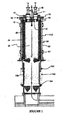
- the improved thermal reaction system disclosed herein has a thermal reaction unit 30 and a lower quenching chamber 150 as shown in Fig. 1 .
- the thermal reaction unit 30 includes a thermal reaction chamber 32, and an inlet adaptor 10 including a top plate 18, at least one waste gas inlet 14, at least one fuel inlet 17, optionally at least one oxidant inlet 11, burner jets 15, a center jet 16 and an interior plate 12 which is positioned at or within the thermal reaction chamber 32 (see also Fig. 3 for a schematic of the inlet adaptor independent of the thermal reaction unit).
- the inlet adaptor includes the fuel and oxidant gas inlets to provide a fuel rich gas mixture to the system for the destruction of contaminants.
- the fuel and oxidant may be pre-mixed prior to introduction into the thermal reaction chamber.
- Fuels contemplated herein include, but are not limited to, hydrogen, methane, natural gas, propane, LPG and city gas, preferably natural gas.
- Oxidants contemplated herein include, but are limited to, oxygen, ozone, air, clean dry air (CDA) and oxygen-enriched air.
- Waste gases to be abated comprise a species selected from the group consisting of CF 4 , C 2 F 6 , SF 6 , C 3 F 8 , C 4 H 8 , C 4 H 8 O, SiF 4 , BF 3 , NF 3 , BH 3 , B 2 H 6 , B 5 H 9 , NH 3 , PH 3 , SiH 4 , SeH 2 , F 2 , Cl 2 , HCl, HF, HBr, WF 6 , H 2 , Al(CH 3 ) 3 , primary and secondary amines, organosilanes, organometallics, and halosilanes.
- the interior walls of the waste gas inlet 14 may be altered to reduce the affinity of particles for the interior walls of the inlet.
- a surface may be electropolished to reduce the mechanical roughness (Ra) to a value less than 30, more preferably less than 17, most preferably less than 4. Reducing the mechanical roughness reduces the amount of particulate matter that adheres to the surface as well as improving the corrosion resistance of the surface.
- the interior wall of the inlet may be coated with a fluoropolymer coating, for example Teflon® or Halar®, which will also act to reduce the amount of particulate matter adhered at the interior wall as well as allow for easy cleaning.
- the fluoropolymer coating is applied as follows. First the surface to be coated is cleaned with a solvent to remove oils, etc. Then, the surface is bead-blasted to provide texture thereto. Following texturization, a pure layer of fluoropolymer, e.g., Teflon®, a layer of ceramic filled fluoropolymer, and another pure layer of fluoropolymer are deposited on the surface in that order. The resultant fluoropolymer-containing layer is essentially scratch-resistant.
- the waste gas inlet 14 tube is subjected to thermophoresis, wherein the interior wall of the inlet is heated thereby reducing particle adhesion thereto.
- Thermophoresis may be effected by actually heating the surface of the includes a thermal reaction chamber 32, and an inlet adaptor 10 including a top plate 18, at least one waste gas inlet 14, at least one fuel inlet 17, optionally at least one oxidant inlet 11, burner jets 15, a center jet 16 and an interior plate 12 which is positioned at or within the thermal reaction chamber 32 (see also Fig. 3 for a schematic of the inlet adaptor independent of the thermal reaction unit).
- the inlet adaptor includes the fuel and oxidant gas inlets to provide a fuel rich gas mixture to the system for the destruction of contaminants.
- the fuel and oxidant may be pre-mixed prior to introduction into the thermal reaction chamber.
- Fuels contemplated herein include, but are not limited to, hydrogen, methane, natural gas, propane, LPG and city gas, preferably natural gas.
- Oxidants contemplated herein include, but are limited to, oxygen, ozone, air, clean dry air (CDA) and oxygen-enriched air.
- Waste gases to be abated comprise a species selected from the group consisting of CF 4 , C 2 F 6 , SF 6 , C 3 F 8 , C 4 H 8 , C 4 H 8 O, SiF 4 , BF 3 , NF 3 , BH 3 , B 2 H 6 , B 5 H 9 , NH 3 , PH 3 , SiH 4 , SeH 2 , F 2 , Cl 2 , HCl, HF, HBr, WF 6 , H 2 , Al(CH 3 ) 3 , primary and secondary amines, organosilanes, organometallics, and halosilanes.
- the interior walls of the waste gas inlet 14 may be altered to reduce the affinity of particles for the interior walls of the inlet.
- a surface may be electropolished to reduce the mechanical roughness (Ra) to a value less than 30, more preferably less than 17, most preferably less than 4. Reducing the mechanical roughness reduces the amount of particulate matter that adheres to the surface as well as improving the corrosion resistance of the surface.
- the interior wall of the inlet may be coated with a fluoropolymer coating, for example Teflon® or Halar®, which will also act to reduce the amount of particulate matter adhered at the interior wall as well as allow for easy cleaning.
- the fluoropolymer coating is applied as follows. First the surface to be coated is cleaned with a solvent to remove oils, etc. Then, the surface is bead-blasted to provide texture thereto. Following texturization, a pure layer of fluoropolymer, e.g., Tellon®, a layer of ceramic filled fluoropolymer, and another pure layer of fluoropolymer are deposited on the surface in that order. The resultant fluoropolymer-containing layer is essentially scratch-resistant.
- the waste gas inlet 14 tube is subjected to thermophoresis, wherein the interior wall of the inlet is heated thereby reducing particle adhesion thereto.
- Thermophoresis may be effected by actually heating the surface of the and high resistance to corrosion at elevated temperatures.
- the voids are uniformly distributed throughout the material and the voids are of a size that permits fluids to easily diffuse through the material.
- the ceramic foam bodies should not react appreciably with PFC's in the effluent to form highly volatile halogen species.
- the ceramic foam bodies may include alumina materials, magnesium oxide, refractory metal oxides such as ZrO 2 , silicon carbide and silicon nitride, preferably higher purity alumina materials, e.g., spinel, and yttria-doped alumina materials.
- the ceramic foam bodies are ceramic bodies formed from yttria-doped alumina materials and yttria-stabilized zirconia-alumina (YZA). The preparation of ceramic foam bodies is well within the knowledge of those skilled in the art.
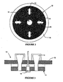
- a fluid inlet passageway may be incorporated into the center jet 16 of the inlet adaptor 10 (see for example Figs. 1 , 3 and 5 for placement of the center jet in the inlet adaptor).
- An embodiment of the center jet 16 is illustrated in Fig. 4 , said center jet including a pilot injection manifold tube 24, pilot ports 26, a pilot flame protective plate 22 and a fastening means 28, e.g., threading complementary to threading on the inlet adaptor, whereby the center jet and the inlet adaptor may be complementarily mated with one another in a leak-tight fashion.
- the pilot flame of the center jet 16 is used to ignite the burner jets 15 of the inlet adaptor.
- a bore-hole 25 Through the center of the center jet 16 is a bore-hole 25 through which a stream of high velocity fluid may be introduced to inject into the thermal reaction chamber 32 (see, e.g., Fig. 5 ).
- the high velocity fluid may include any gas sufficient to reduce deposition on the interior walls of the thermal reaction unit while not detrimentally affecting the abatement treatment in the thermal reaction chamber.
- the fluid may be introduced in a continuous or a pulsating mode, preferably a continuous mode.
- Gases contemplated herein include air, CDA, oxygen-enriched air, oxygen, ozone and inert gases, e.g., Ar, N 2 , etc.
- the gas is CDA and may be oxygen-enriched.
- the high velocity fluid is heated prior to introduction into the thermal reaction chamber.
- the thermal reaction unit includes a porous ceramic cylinder design defining the thermal reaction chamber 32.
- High velocity air may be directed through the pores of the thermal reaction unit 30 to at least partially reduce particle buildup on the interior walls of the thermal reaction unit.
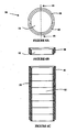
- the ceramic cylinder of the present invention includes at least two ceramic rings stacked upon one another, for example as illustrated in Fig. 6C . More preferably, the ceramic cylinder includes at least about two to about twenty rings stacked upon one another. It is understood that the term "ring" is not limited to circular rings per se, but may also include rings of any polygonal or elliptical shape. Preferably, the rings are generally tubular in form.
- Figure 6C is a partial cut-away view of the ceramic cylinder design of the present invention showing the stacking of the individual ceramic rings 36 having a complimentary ship-lap joint design, wherein the stacked ceramic rings define the thermal reaction chamber 32.
- the uppermost ceramic ring 40 is designed to accommodate the inlet adaptor.
- the joint design is not limited to lap joints but may also include beveled joints, butt joints, lap joints and tongue and groove joints. Gasketing or sealing means, e.g., GRAFOIL® or other high temperature materials, positioned between the stacked rings is contemplated herein, especially if the stacked ceramic rings are butt jointed.
- the joints between the stacked ceramic rings overlap, e.g., ship-lap, to prevent infrared radiation from escaping from the thermal reaction chamber.
- Each ceramic ring may be a circumferentially continuous ceramic ring or alternatively, may be at least two sections that may be joined together to make up the ceramic ring.
- Figure 6A illustrates the latter embodiment, wherein the ceramic ring 36 includes a first arcuate section 38 and a second arcuate section 40, and when the first and second arcuate sections are coupled together, a ring is formed that defines a portion of the thermal reaction chamber 32.
- the ceramic rings are preferably formed of the same materials as the ceramic foam bodies discussed previously, e.g., YZA.
- the advantage of having a thermal reaction chamber defined by individual stacked ceramic rings includes the reduction of cracking of the ceramic rings of the chamber due to thermal shock and concomitantly a reduction of equipment costs. For example, if one ceramic ring cracks, the damaged ring may be readily replaced for a fraction of the cost and the thermal reactor placed back online immediately.
- the ceramic rings of the invention must be held to another to form the thermal reaction unit 30 whereby high velocity air may be directed through the pores of the ceramic rings of the thermal reaction unit to at least partially reduce particle buildup at the interior walls of the thermal reaction unit.
- a perforated metal shell may be used to encase the stacked ceramic rings of the thermal reaction unit as well as control the flow of axially directed air through the porous interior walls of the thermal reaction unit.
- Figure 7 illustrates an embodiment of the perforated metal shell 110 of the present invention, wherein the metal shell has the same general form of the stacked ceramic rings, e.g., a circular cylinder or a polygonal cylinder, and the metal shell includes at least two attachable sections 112 that may be joined together to make up the general form of the ceramic cylinder.
- the two attachable sections 112 include ribs 114, e.g., clampable extensions 114, which upon coupling put pressure on the ceramic rings thereby holding the rings to one another.
- the metal shell 110 has a perforated pattern whereby preferably more air is directed towards the top of the thermal reaction unit, e.g., the portion closer to the inlet adaptor 10, than the bottom of the thermal reaction unit, e.g., the lower chamber (see Figs. 7 and 8 ).
- the perforated pattern is the same throughout the metal shell.
- "perforations" may represent any array of openings through the metal shell that do not compromise the integrity and strength of the metal shell, while ensuring that the flow of axially directed air through the porous interior walls may be controlled.
- the perforations may be holes having circular, polygonal or elliptical shapes or in the alternative, the perforations may be slits of various lengths and widths.
- the perforations are holes 1,6 mm (1/16") in diameter, and the perforation pattern towards the top of the thermal reaction unit has 1 hole per 645 mm 2 (1 hole per square inch), while the perforation pattern towards the bottom of the thermal reaction unit has 0.5 holes per 645 mm 2 (square inch).
- the perforation area is about 0.1 % to 1 % of the area of the metal shell.
- the metal shell is constructed from corrosion-resistant metals including, but not limited to: stainless steel; austenitic nickel-chromium-iron alloys such as Inconel® 600, 601, 617, 625, 625 LCF, 706, 718, 718 SPF, X-750, MA754, 783, 792, and HX; and other nickel-based alloys such as Hastelloy B, B2, C, C22, C276, C2000, G, G2, G3 and G30.
- austenitic nickel-chromium-iron alloys such as Inconel® 600, 601, 617, 625, 625 LCF, 706, 718, 718 SPF, X-750, MA754, 783, 792, and HX
- other nickel-based alloys such as Hastelloy B, B2, C, C22, C276, C2000, G, G2, G3 and G30.
- the thermal reaction unit of the invention is illustrated.
- the ceramic rings 36 are stacked upon one another, at least one layer of a fibrous blanket is wrapped around the exterior of the stacked ceramic rings and then the sections 112 of the metal shell 110 are positioned around the fibrous blanket and tightly attached together by coupling the ribs 114.
- the fibrous blanket can be any fibrous inorganic material having a low thermal conductivity, high temperature capability and an ability to deal with the thermal expansion coefficient mismatch of the metal shell and the ceramic rings.
- Fibrous blanket material contemplated herein includes, but is not limited to, spinel fibers, glass wool and other materials comprising aluminum silicates.
- the fibrous blanket may be a soft ceramic sleeve.
- fluid flow is axially and controllably introduced through the perforations of the metal shell, the fibrous blanket and the reticulated ceramic rings of the cylinder.
- the fluid experiences a pressure drop from the exterior of the thermal reaction unit to the interior of the thermal reaction unit in a range from about 3,4 hPa to about 21 hPa , preferably about 7hPa to 14 hPa (0.05 psi to about 0.30 psi, preferably about 0.1 psi to 0.2 psi).
- the fluid may be introduced in a continuous or a pulsating mode, preferably a continuous mode to reduce the recirculation of the fluid within the thermal reaction chamber.
- the fluid may include any gas sufficient to reduce deposition on the interior walls of the ceramic rings while not detrimentally affecting the abatement treatment in the thermal reaction chamber.
- Gases contemplated include air, CDA, oxygen-enriched air, oxygen, ozone and inert gases, e.g., Ar, N 2 , etc.
- the entire thermal reaction unit 30 is encased within an outer stainless steel reactor shell 60 (see, e.g., Fig. 1 ), whereby an annular space 62 is created between the interior wall of the outer reactor shell 60 and the exterior wall of the thermal reaction unit 30. Fluids to be introduced through the walls of the thermal reaction unit may be introduced at ports 64 positioned on the outer reactor shell 60.
- the interior plate 12 of the inlet adaptor 10 is positioned at or within the thermal reaction chamber 32 of the thermal reaction unit 30.
- a gasket or seal 42 is preferably positioned between the top ceramic ring 40 and the top plate 18 (see, e.g., Fig. 9 ).
- the gasket or seal 42 may be GRAFOIL® or some other high temperature material that will prevent leakage of blow-off air through the top plate/thermal reaction unit joint, i.e., to maintain a backpressure behind the ceramic rings for gas distribution.
- Figs. 10A and 10B show the buildup of particulate matter on a prior art interior plate and an interior plate according to the present invention, respectively. It can be seen that the buildup on the interior plate of the present invention (having a reticulated foam plate with fluid emanating from the pores, a reticulated ceramic cylinder with fluid emanating from the pores and high velocity fluid egression from the center jet) is substantially reduced relative to the interior plate of the prior art, which is devoid of the novel improvements disclosed herein.
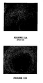
- Figs. 11A and 11B illustrate prior art thermal reaction units and the thermal reaction unit according to the present invention, respectively. It can be seen that the buildup of particulate matter on the interior walls of the thermal reaction unit of the present invention is substantially reduced relative to prior art thermal reaction unit walls. Using the apparatus and method described herein, the amount of particulate buildup at the interior walls of the thermal reaction unit is reduced by at least 50%, preferably at least 70% and more preferably at least 80%, relative to prior art units oxidizing an equivalent amount of effluent gas.
- the water quenching means Downstream of the thermal reaction chamber is a water quenching means positioned in the lower quenching chamber 150 to capture the particulate matter that egresses from the thermal reaction chamber.
- the water quenching means may include a water curtain as disclosed in co-pending U.S. Patent Application No. 10/249,703 in the name of Glenn Tom et al. , entitled “Gas Processing System Comprising a Water Curtain for Preventing Solids Deposition on Interior Walls Thereof,". Referring to Fig.
- the water for the water curtain is introduced at inlet 152 and water curtain 156 is formed, whereby the water curtain absorbs the heat of the combustion and decomposition reactions occurring in the thermal reaction unit 30, eliminates build-up of particulate matter on the walls of the lower quenching chamber 150, and absorbs water soluble gaseous products of the decomposition and combustion reactions, e.g., CO 2 , HF, etc.
- a shield 202 may be positioned between the bottom-most ceramic ring 198 and the water curtain in the lower chamber 150.
- the shield is L-shaped and assumes the three-dimensional form of the bottom-most ceramic ring, e.g., a circular ring, so that water does not come in contact with the bottom-most ceramic ring.
- the shield may be constructed from any material that is water- and corrosion-resistant and thermally stable including, but not limited to: stainless steel; austenitic nickel-chromium- iron alloys such as Inconel® 600, 601, 617, 625, 625 LCF, 706, 718, 718 SPF, X-750, MA754, 783, 792, and HX; and other nickel-based alloys such as Hastelloy B, B2, C, C22, C276, C2000, G, G2, G3 and G30.
- austenitic nickel-chromium- iron alloys such as Inconel® 600, 601, 617, 625, 625 LCF, 706, 718, 718 SPF, X-750, MA754, 783, 792, and HX
- other nickel-based alloys such as Hastelloy B, B2, C, C22, C276, C2000, G, G2, G3 and G30.
- effluent gases enter the thermal reaction chamber 32 from at least one inlet provided in the inlet adaptor 10, and the fuel/oxidant mixture enter the thermal reaction chamber 32 from at least one burner jet 15.
- the pilot flame of the center jet 16 is used to ignite the burner jets 15 of the inlet adaptor, creating thermal reaction unit temperatures in a range from about 500°C to about 2000°C.
- the high temperatures facilitate decomposition of the effluent gases that are present within the thermal reaction chamber. It is also possible that some effluent gases undergo combustion/oxidation in the presence of the fuel/oxidant mixture.
- the pressure within the thermal reaction chamber is in a range from about 0.5 atm to about 5 atm, preferably slightly subatmospheric, e.g., about 0.98 atm to about 0.99 atm.
- a water curtain 156 may be used to cool the walls of the lower chamber and inhibit deposition of particulate matter on the walls. It is contemplated that some particulate matter and water soluble gases may be removed from the gas stream using the water curtain 156. Further downstream of the water curtain, a water spraying means 154 may be positioned within the lower quenching chamber 150 to cool the gas stream, and remove the particulate matter and water soluble gases. Cooling the gas stream allows for the use of lower temperature materials downstream of the water spraying means thereby reducing material costs.
- Gases passing through the lower quenching chamber may be released to the atmosphere or alternatively may be directed to additional treatment units including, but not limited to, liquid/liquid scrubbing, physical and/or chemical adsorption, coal traps, electrostatic precipitators, and cyclones.
- additional treatment units including, but not limited to, liquid/liquid scrubbing, physical and/or chemical adsorption, coal traps, electrostatic precipitators, and cyclones.
- the concentration of the effluent gases is preferably below detection limits, e.g., less than 1 ppm.
- the apparatus described herein removes greater than 90% of the toxic effluent components that enter the abatement apparatus, preferably greater than 98%, most preferably greater than 99.9%.
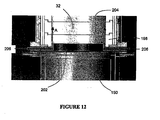
- an "air knife” is positioned within the thermal reaction unit.
- fluid may be intermittently injected into the air knife inlet 206, which is situated between the bottom-most ceramic ring 198 and the water quenching means in the lower quenching chamber 150.
- the air knife inlet 206 may be incorporated into the shield 202 which prevents water from wetting the bottom-most ceramic ring 198 as described hereinabove.
- the air knife fluid may include any gas sufficient to reduce deposition on the interior walls of the thermal reaction unit while not detrimentally affecting the decomposition treatment in said unit. Gases contemplated include air, CDA, oxygen-enriched air, oxygen, ozone and inert gases, e.g., Ar, N 2 , etc.
- gas is intermittently injected through the air knife inlet 206 and exits a very thin slit 204 that is positioned parallel to the interior wall of the thermal reaction chamber 32.
- gases are directed upwards along the wall (in the direction of the arrows in Fig. 12 ) to force any deposited particulate matter from the surface of the interior wall.
Landscapes
- Engineering & Computer Science (AREA)
- Mechanical Engineering (AREA)
- General Engineering & Computer Science (AREA)
- Environmental & Geological Engineering (AREA)
- Chemical & Material Sciences (AREA)
- Combustion & Propulsion (AREA)
- Physical Or Chemical Processes And Apparatus (AREA)
- Incineration Of Waste (AREA)
- Devices And Processes Conducted In The Presence Of Fluids And Solid Particles (AREA)
- Treating Waste Gases (AREA)
Abstract
Claims (15)
- Réacteur thermique pour éliminer les polluants d'un gaz résiduaire, le réacteur thermique comprenant :une unité de réaction thermique (30) comprenant :i) une paroi extérieure (110) ayant une pluralité de perforations pour le passage d'un fluide à travers elle ;ii) une paroi intérieure en céramique poreuse définissant une chambre de réaction thermique (32) ;iii) au moins une entrée de gaz résiduaire (14) en communication de fluide avec la chambre de réaction thermique (32) pour introduire un gaz résiduaire à l'intérieur de celle-ci ; etiv) au moins une entrée de combustible (17) en communication de fluide avec la chambre de réaction thermique (32) pour introduire un combustible pour utilisation pendant la décomposition dudit gaz résiduaire dans la chambre de réaction thermique (32) ; etv) des moyens pour diriger un fluide à travers la ou les perforations de la paroi extérieure (110) et la paroi intérieure en céramique poreuse pour réduire le dépôt et l'accumulation de matière particulaire sur celles-ci ; etune unité de refroidissement à l'eau (150) couplée à l'unité de réaction thermique (30) et adaptée pour recevoir un flux de gaz provenant de l'unité de réaction thermique (30) ;caractérisé en ce quela paroi intérieure comprend au moins deux sections annulaires (36, 38, 40) dans un agencement empilé ; etdans lequel le nombre total de perforations à proximité de l'entrée de gaz résiduaire (14) et de l'entrée de combustible (17) est supérieur au nombre total de perforations à proximité de l'unité de refroidissement à l'eau (150).
- Réacteur thermique selon la revendication 1, couplé en relation de réception de gaz résiduaire à une installation de traitement choisie dans le groupe constitué par une installation de traitement de fabrication de semi-conducteurs et une installation de traitement d'affichages à cristaux liquides (LCD).
- Réacteur thermique selon la revendication 1, dans lequel la paroi intérieure en céramique poreuse (36) a une forme généralement tubulaire.
- Réacteur thermique selon la revendication 3, dans lequel la forme généralement tubulaire comprend une forme choisie dans le groupe constitué par les formes cylindriques, polygonales et elliptiques.
- Réacteur thermique selon la revendication 3, dans lequel chacune des au moins deux sections annulaires (36, 38, 40) est de forme arquée.
- Réacteur thermique selon la revendication 1, dans lequel la paroi extérieure (110) comprend un métal résistant à la corrosion et stable thermiquement.
- Réacteur thermique selon la revendication 1, dans lequel la paroi extérieure (110) présente des perforations qui fournissent une chute de pression à travers l'unité de réaction thermique supérieure à environ 7 hPa (0,1 psi).
- Réacteur thermique selon la revendication 1, dans lequel la paroi extérieure (110) comprend au moins deux sections couplées (112).
- Réacteur thermique selon la revendication 1, comprenant en outre un matériau fibreux disposé entre la paroi extérieure (110) et la paroi intérieure en céramique poreuse (36).
- Réacteur thermique selon la revendication 1, dans lequel la paroi intérieure comprend au moins environ vingt sections annulaires (36).
- Réacteur thermique selon la revendication 1, dans lequel les au moins deux sections annulaires (36) sont assemblées de façon complémentaire pour la connexion d'anneaux empilés adjacents.
- Réacteur thermique selon la revendication 1, comprenant en outre au moins une entrée d'oxydant (11) en communication de fluide avec la chambre de réaction thermique (32) pour l'introduction d'oxydant pour mélange avec le combustible.
- Réacteur thermique selon la revendication 1, dans lequel l'unité de réaction thermique (30) comprend en outre une plaque en céramique poreuse (12) positionnée au niveau ou au sein de la paroi intérieure (36) de la chambre de réaction thermique (32), et dans lequel la plaque en céramique poreuse (12) renferme une extrémité de ladite chambre de réaction thermique (32).
- Réacteur thermique selon la revendication 13, comprenant en outre une tuyère centrale (11) en communication de fluide avec la chambre de réaction thermique (32), dans lequel la tuyère centrale (11) est à proximité de l'au moins une entrée de gaz résiduaire (14) et de l'au moins une entrée de combustible (17), et dans lequel la tuyère centrale (11) est adaptée pour introduire du fluide à haute vitesse dans la chambre de réaction thermique (32) à travers la tuyère centrale (11) pendant la décomposition du gaz résiduaire pour empêcher le dépôt et l'accumulation de matière particulaire sur la paroi intérieure (36) et la plaque en céramique poreuse (12) de la chambre de réaction thermique (32) à proximité de la tuyère centrale (11).
- Réacteur thermique selon la revendication 1, comprenant en outre une enveloppe de réacteur externe (60) ayant une paroi intérieure d'enveloppe de réacteur, dans lequel un espace annulaire (62) est formé entre la paroi intérieure d'enveloppe de réacteur externe et la paroi extérieure de l'unité de réaction thermique (30).
Applications Claiming Priority (2)
| Application Number | Priority Date | Filing Date | Title |
|---|---|---|---|
| US10/987,921 US7736599B2 (en) | 2004-11-12 | 2004-11-12 | Reactor design to reduce particle deposition during process abatement |
| PCT/US2005/040960 WO2006053231A2 (fr) | 2004-11-12 | 2005-11-12 | Conception d'un reacteur reduisant le depot de particules pendant le processus de reduction |
Publications (2)
| Publication Number | Publication Date |
|---|---|
| EP1828680A2 EP1828680A2 (fr) | 2007-09-05 |
| EP1828680B1 true EP1828680B1 (fr) | 2012-02-01 |
Family
ID=36115480
Family Applications (1)
| Application Number | Title | Priority Date | Filing Date |
|---|---|---|---|
| EP05820049A Expired - Fee Related EP1828680B1 (fr) | 2004-11-12 | 2005-11-12 | Conception d'un réacteur réduisant les dépôts de particules dans un procédé de réduction des effluents |
Country Status (8)
| Country | Link |
|---|---|
| US (2) | US7736599B2 (fr) |
| EP (1) | EP1828680B1 (fr) |
| JP (1) | JP2008519959A (fr) |
| KR (1) | KR20070086017A (fr) |
| CN (1) | CN101069041B (fr) |
| IL (1) | IL183122A0 (fr) |
| TW (2) | TW201023244A (fr) |
| WO (1) | WO2006053231A2 (fr) |
Families Citing this family (75)
| Publication number | Priority date | Publication date | Assignee | Title |
|---|---|---|---|---|
| US7569193B2 (en) * | 2003-12-19 | 2009-08-04 | Applied Materials, Inc. | Apparatus and method for controlled combustion of gaseous pollutants |
| US7316721B1 (en) * | 2004-02-09 | 2008-01-08 | Porvair, Plc | Ceramic foam insulator with thermal expansion joint |
| US7736599B2 (en) * | 2004-11-12 | 2010-06-15 | Applied Materials, Inc. | Reactor design to reduce particle deposition during process abatement |
| US7682574B2 (en) * | 2004-11-18 | 2010-03-23 | Applied Materials, Inc. | Safety, monitoring and control features for thermal abatement reactor |
| US8095240B2 (en) * | 2004-11-18 | 2012-01-10 | Applied Materials, Inc. | Methods for starting and operating a thermal abatement system |
| GB0509163D0 (en) * | 2005-05-05 | 2005-06-15 | Boc Group Plc | Gas combustion apparatus |
| US8617672B2 (en) | 2005-07-13 | 2013-12-31 | Applied Materials, Inc. | Localized surface annealing of components for substrate processing chambers |
| WO2007053626A2 (fr) * | 2005-10-31 | 2007-05-10 | Applied Materials, Inc. | Reacteur de moderation de process |
| EP1994456A4 (fr) | 2006-03-16 | 2010-05-19 | Applied Materials Inc | Procédés et appareil permettant de commander la pression dans des systèmes de fabrication de dispositifs électroniques |
| US7522974B2 (en) * | 2006-08-23 | 2009-04-21 | Applied Materials, Inc. | Interface for operating and monitoring abatement systems |
| TW200832097A (en) * | 2006-08-23 | 2008-08-01 | Applied Materials Inc | Systems and methods for operating and monitoring abatement systems |
| US20080092806A1 (en) * | 2006-10-19 | 2008-04-24 | Applied Materials, Inc. | Removing residues from substrate processing components |
| US8591819B2 (en) * | 2006-12-05 | 2013-11-26 | Ebara Corporation | Combustion-type exhaust gas treatment apparatus |
| US7981262B2 (en) | 2007-01-29 | 2011-07-19 | Applied Materials, Inc. | Process kit for substrate processing chamber |
| EP2150360A4 (fr) * | 2007-05-25 | 2013-01-23 | Applied Materials Inc | Procédés et appareil d'exploitation efficace d'un système d'assainissement |
| US7942969B2 (en) | 2007-05-30 | 2011-05-17 | Applied Materials, Inc. | Substrate cleaning chamber and components |
| US20090018688A1 (en) * | 2007-06-15 | 2009-01-15 | Applied Materials, Inc. | Methods and systems for designing and validating operation of abatement systems |
| DE102007042543A1 (de) * | 2007-09-07 | 2009-03-12 | Choren Industries Gmbh | Verfahren und Vorrichtung zur Behandlung von beladenem Heißgas |
| KR20100084676A (ko) * | 2007-10-26 | 2010-07-27 | 어플라이드 머티어리얼스, 인코포레이티드 | 향상된 연료 회로를 사용하는 스마트 저감을 위한 방법 및 장치 |
| US20090149996A1 (en) * | 2007-12-05 | 2009-06-11 | Applied Materials, Inc. | Multiple inlet abatement system |
| KR100901267B1 (ko) * | 2008-01-25 | 2009-06-09 | 고등기술연구원연구조합 | 산소 부화식 합성가스 연소장치 |
| KR101555469B1 (ko) * | 2008-02-05 | 2015-09-24 | 어플라이드 머티어리얼스, 인코포레이티드 | 전자 디바이스 제조 시스템을 동작하기 위한 방법 및 장치 |
| KR101581673B1 (ko) * | 2008-02-05 | 2015-12-31 | 어플라이드 머티어리얼스, 인코포레이티드 | 제조 프로세스들로부터의 가연성 폐기물 가스들을 처리하기 위한 시스템 및 방법 |
| EP2090825A1 (fr) * | 2008-02-14 | 2009-08-19 | Siemens Aktiengesellschaft | Elément de brûleur et brûleur doté d'une garniture résistant à la corrosion |
| US20100119984A1 (en) * | 2008-11-10 | 2010-05-13 | Fox Allen G | Abatement system |
| US8596075B2 (en) | 2009-02-26 | 2013-12-03 | Palmer Labs, Llc | System and method for high efficiency power generation using a carbon dioxide circulating working fluid |
| US9068743B2 (en) * | 2009-02-26 | 2015-06-30 | 8 Rivers Capital, LLC & Palmer Labs, LLC | Apparatus for combusting a fuel at high pressure and high temperature, and associated system |
| US10018115B2 (en) | 2009-02-26 | 2018-07-10 | 8 Rivers Capital, Llc | System and method for high efficiency power generation using a carbon dioxide circulating working fluid |
| US8986002B2 (en) * | 2009-02-26 | 2015-03-24 | 8 Rivers Capital, Llc | Apparatus for combusting a fuel at high pressure and high temperature, and associated system |
| EA024852B1 (ru) | 2009-02-26 | 2016-10-31 | Палмер Лэбз, Ллк | Способ и устройство для сжигания топлива при высокой температуре и высоком давлении и соответствующие система и средства |
| WO2011162023A1 (fr) * | 2010-06-21 | 2011-12-29 | エドワーズ株式会社 | Système de traitement de gaz |
| KR101253698B1 (ko) * | 2010-08-06 | 2013-04-11 | 주식회사 글로벌스탠다드테크놀로지 | 폐 가스 정화용 연소장치 |
| US8869889B2 (en) | 2010-09-21 | 2014-10-28 | Palmer Labs, Llc | Method of using carbon dioxide in recovery of formation deposits |
| CN104160130B (zh) | 2011-11-02 | 2017-08-25 | 八河流资产有限责任公司 | 发电系统和相应方法 |
| EP2780483B1 (fr) * | 2011-11-15 | 2017-03-01 | Outotec Oyj | Procédé pour la fabrication de ferrochrome |
| WO2013086217A1 (fr) | 2011-12-06 | 2013-06-13 | Masco Corporation Of Indiana | Distribution d'ozone dans un robinet |
| MX358190B (es) | 2012-02-11 | 2018-08-08 | Palmer Labs Llc | Reaccion de oxidacion parcial con enfriamiento de ciclo cerrado. |
| US9089811B2 (en) * | 2012-04-30 | 2015-07-28 | Highvac Corp. | Coaxial / coaxial treatment module |
| GB2504335A (en) * | 2012-07-26 | 2014-01-29 | Edwards Ltd | Radiant burner for the combustion of manufacturing effluent gases. |
| CN103308662B (zh) * | 2013-06-07 | 2015-07-08 | 北京理工大学 | 一种高温高压单液滴蒸发与燃烧装置 |
| GB2516267B (en) * | 2013-07-17 | 2016-08-17 | Edwards Ltd | Head assembly |
| JP6250332B2 (ja) | 2013-08-27 | 2017-12-20 | 8 リバーズ キャピタル,エルエルシー | ガスタービン設備 |
| CN103529078B (zh) * | 2013-10-25 | 2016-04-13 | 中国人民解放军装备学院 | 一种高温高压环境下液滴蒸发点火实验装置及其使用方法 |
| JP6258797B2 (ja) * | 2014-06-27 | 2018-01-10 | 日本パイオニクス株式会社 | 排ガスの燃焼式浄化装置 |
| CN105090999B (zh) * | 2014-05-12 | 2018-11-20 | 日本派欧尼株式会社 | 废气的燃烧式净化装置 |
| TWI691644B (zh) | 2014-07-08 | 2020-04-21 | 美商八河資本有限公司 | 具改良效率之功率生產方法及系統 |
| GB2528444B (en) * | 2014-07-21 | 2018-06-20 | Edwards Ltd | Abatement apparatus |
| GB2528445B (en) | 2014-07-21 | 2018-06-20 | Edwards Ltd | Separator apparatus |
| US11231224B2 (en) | 2014-09-09 | 2022-01-25 | 8 Rivers Capital, Llc | Production of low pressure liquid carbon dioxide from a power production system and method |
| PL3204331T3 (pl) | 2014-09-09 | 2019-03-29 | 8 Rivers Capital, Llc | Wytwarzanie niskociśnieniowego ditlenku węgla w układach i systemach wytwarzania energii |
| US11686258B2 (en) | 2014-11-12 | 2023-06-27 | 8 Rivers Capital, Llc | Control systems and methods suitable for use with power production systems and methods |
| US10961920B2 (en) | 2018-10-02 | 2021-03-30 | 8 Rivers Capital, Llc | Control systems and methods suitable for use with power production systems and methods |
| MA40950A (fr) | 2014-11-12 | 2017-09-19 | 8 Rivers Capital Llc | Systèmes et procédés de commande appropriés pour une utilisation avec des systèmes et des procédés de production d'énergie |
| MX2017016478A (es) | 2015-06-15 | 2018-05-17 | 8 Rivers Capital Llc | Sistema y metodo para la puesta en marcha de una instalacion de produccion de energia. |
| CN106298421A (zh) * | 2015-06-23 | 2017-01-04 | 应用材料公司 | 用以消除来自离子注入工艺的自燃副产物的方法和装置 |
| GB201515489D0 (en) * | 2015-09-01 | 2015-10-14 | Edwards Ltd | Abatement apparatus |
| CN115093008B (zh) | 2015-12-21 | 2024-05-14 | 德尔塔阀门公司 | 包括消毒装置的流体输送系统 |
| CA3015050C (fr) | 2016-02-18 | 2024-01-02 | 8 Rivers Capital, Llc | Systeme et procede de production d'electricite comprenant la methanation |
| AU2017223264B2 (en) | 2016-02-26 | 2019-08-29 | 8 Rivers Capital, Llc | Systems and methods for controlling a power plant |
| GB2550382B (en) * | 2016-05-18 | 2020-04-22 | Edwards Ltd | Burner Inlet Assembly |
| JP7449090B2 (ja) | 2016-09-13 | 2024-03-13 | 8 リバーズ キャピタル,エルエルシー | 部分酸化を使用した電力生産のためのシステムおよび方法 |
| US10690341B2 (en) | 2017-01-06 | 2020-06-23 | Alzeta Corporation | Systems and methods for improved waste gas abatement |
| CA3055401A1 (fr) | 2017-03-07 | 2018-09-13 | 8 Rivers Capital, Llc | Systeme et procede de fonctionnement de chambre de combustion a combustible mixte pour turbine a gaz |
| CN110662922B (zh) | 2017-03-07 | 2021-08-20 | 八河流资产有限责任公司 | 用于固体燃料及其衍生物的燃烧的系统和方法 |
| SG10202001081TA (en) * | 2017-07-07 | 2020-03-30 | Siw Eng Pte Ltd | Device and system for controlling decomposition oxidation of gaseous pollutants |
| AU2018322996B2 (en) | 2017-08-28 | 2024-02-15 | 8 Rivers Capital, Llc | Low-grade heat optimization of recuperative supercritical co |
| JP7291157B2 (ja) | 2018-03-02 | 2023-06-14 | 8 リバーズ キャピタル,エルエルシー | 二酸化炭素作動流体を用いた電力生成のためのシステムおよび方法 |
| US11572828B2 (en) | 2018-07-23 | 2023-02-07 | 8 Rivers Capital, Llc | Systems and methods for power generation with flameless combustion |
| GB2579197B (en) * | 2018-11-22 | 2021-06-09 | Edwards Ltd | Abatement method |
| GB2584675B (en) * | 2019-06-10 | 2021-11-17 | Edwards Ltd | Inlet assembly for an abatement apparatus |
| CN111412481B (zh) * | 2020-03-19 | 2023-01-10 | 长江存储科技有限责任公司 | 废气处理装置 |
| US20210322911A1 (en) * | 2020-04-16 | 2021-10-21 | Integrated Global Services Inc. | System, method, and apparatus for ameliorating deposits in selective catalytic reduction systems for the reduction of nitrogen oxide emissions in steam methane reformers |
| CN112915718B (zh) * | 2021-01-25 | 2022-05-17 | 北京京仪自动化装备技术股份有限公司 | 半导体制程废气处理设备 |
| CN113058360B (zh) * | 2021-03-17 | 2022-06-21 | 北京京仪自动化装备技术股份有限公司 | 一种在线可拆废气处理装置 |
| CN113058356B (zh) * | 2021-03-17 | 2022-06-21 | 北京京仪自动化装备技术股份有限公司 | 一种处理半导体dpy工艺的废气处理装置 |
Family Cites Families (241)
| Publication number | Priority date | Publication date | Assignee | Title |
|---|---|---|---|---|
| US1759498A (en) * | 1924-05-01 | 1930-05-20 | Abrate Attilio | Carburetor |
| US2819151A (en) * | 1954-03-02 | 1958-01-07 | Flemmert Gosta Lennart | Process for burning silicon fluorides to form silica |
| BE609721A (fr) | 1960-11-03 | 1962-02-15 | Goesta Lennart Flemmert | Méthode de récupération du bioxyde de silicium finement divisé obtenu en faisant réagir en phase gazeuse des composés de silicium et de fluor avec de l'eau |
| US3185846A (en) | 1961-05-16 | 1965-05-25 | Bailey Meter Co | Ultra-violet radiation flame monitor |
| DE1221755B (de) | 1963-12-19 | 1966-07-28 | Appbau Eugen Schrag Kommanditg | Steuer- und Sicherheitsvorrichtung fuer Gas- oder OElfeuerung |
| US3603711A (en) | 1969-09-17 | 1971-09-07 | Edgar S Downs | Combination pressure atomizer and surface-type burner for liquid fuel |
| BE756604A (fr) | 1969-09-26 | 1971-03-01 | Electronics Corp America | Dispositif analyseur, notamment pour la regulation d'une combustion |
| US3983021A (en) | 1971-06-09 | 1976-09-28 | Monsanto Company | Nitrogen oxide decomposition process |
| US3698696A (en) | 1971-06-14 | 1972-10-17 | Standard Int Corp | Combustion mixture control system for calenders |
| US3969485A (en) | 1971-10-28 | 1976-07-13 | Flemmert Goesta Lennart | Process for converting silicon-and-fluorine-containing waste gases into silicon dioxide and hydrogen fluoride |
| NO131825C (fr) * | 1972-03-22 | 1975-08-13 | Elkem Spigerverket As | |
| US3845191A (en) | 1972-06-02 | 1974-10-29 | Du Pont | Method of removing halocarbons from gases |
| US3898040A (en) | 1972-06-29 | 1975-08-05 | Universal Oil Prod Co | Recuperative form of thermal-catalytic incinerator |
| US3949057A (en) * | 1973-01-29 | 1976-04-06 | Croll-Reynolds Company, Inc. | Air pollution control of oxides of nitrogen |
| JPS5643771B2 (fr) * | 1973-12-18 | 1981-10-15 | ||
| US3969482A (en) | 1974-04-25 | 1976-07-13 | Teller Environmental Systems, Inc. | Abatement of high concentrations of acid gas emissions |
| US4059386A (en) | 1976-01-21 | 1977-11-22 | A. O. Smith Corporation | Combustion heating apparatus to improve operation of gas pilot burners |
| US4083607A (en) * | 1976-05-05 | 1978-04-11 | Mott Lambert H | Gas transport system for powders |
| US4206189A (en) * | 1977-01-04 | 1980-06-03 | Belov Viktor Y | Method of producing hydrogen fluoride and silicon dioxide from silicon tetra-fluoride |
| NL7704399A (nl) | 1977-04-22 | 1978-10-24 | Shell Int Research | Werkwijze en reactor voor de partiele ver- branding van koolpoeder. |
| US4154141A (en) * | 1977-05-17 | 1979-05-15 | The United States Of America As Represented By The Secretary Of The Army | Ultrafast, linearly-deflagration ignition system |
| US4296079A (en) | 1978-02-10 | 1981-10-20 | Vinings Chemical Company | Method of manufacturing aluminum sulfate from flue gas |
| US4236464A (en) | 1978-03-06 | 1980-12-02 | Aerojet-General Corporation | Incineration of noxious materials |
| DE2932129A1 (de) | 1978-08-25 | 1980-02-28 | Satronic Ag | Flammenwaechter an oel- oder gasbrennern |
| US4238460A (en) | 1979-02-02 | 1980-12-09 | United States Steel Corporation | Waste gas purification systems and methods |
| US4243372A (en) * | 1979-02-05 | 1981-01-06 | Electronics Corporation Of America | Burner control system |
| US4519999A (en) * | 1980-03-31 | 1985-05-28 | Union Carbide Corporation | Waste treatment in silicon production operations |
| CH649274A5 (de) | 1980-10-14 | 1985-05-15 | Maerz Ofenbau | Kalzinierofen zum brennen von kalkstein und aehnlichen mineralischen rohstoffen. |
| US4374649A (en) * | 1981-02-12 | 1983-02-22 | Burns & Roe, Inc. | Flame arrestor |
| US4479443A (en) | 1982-03-08 | 1984-10-30 | Inge Faldt | Method and apparatus for thermal decomposition of stable compounds |
| US4479809A (en) | 1982-12-13 | 1984-10-30 | Texaco Inc. | Apparatus for gasifying coal including a slag trap |
| US4483672A (en) | 1983-01-19 | 1984-11-20 | Essex Group, Inc. | Gas burner control system |
| US4584001A (en) * | 1983-08-09 | 1986-04-22 | Vbm Corporation | Modular oxygen generator |
| US4541995A (en) | 1983-10-17 | 1985-09-17 | W. R. Grace & Co. | Process for utilizing doubly promoted catalyst with high geometric surface area |
| US4788036A (en) | 1983-12-29 | 1988-11-29 | Inco Alloys International, Inc. | Corrosion resistant high-strength nickel-base alloy |
| CA1225441A (fr) * | 1984-01-23 | 1987-08-11 | Edward S. Fox | Incineration des dechets par pyrolyse avec apport de plasma |
| US4555389A (en) | 1984-04-27 | 1985-11-26 | Toyo Sanso Co., Ltd. | Method of and apparatus for burning exhaust gases containing gaseous silane |
| US5137701A (en) | 1984-09-17 | 1992-08-11 | Mundt Randall S | Apparatus and method for eliminating unwanted materials from a gas flow line |
| JPS61204022A (ja) * | 1985-02-12 | 1986-09-10 | Taiyo Sanso Kk | ガス中の酸分の除去方法及び装置 |
| DE3539127C1 (de) * | 1985-11-05 | 1987-01-02 | Hoechst Ag | Verfahren zur Herstellung eines Traegerkatalysators |
| US4801437A (en) * | 1985-12-04 | 1989-01-31 | Japan Oxygen Co., Ltd. | Process for treating combustible exhaust gases containing silane and the like |
| US4661056A (en) * | 1986-03-14 | 1987-04-28 | American Hoechst Corporation | Turbulent incineration of combustible materials supplied in low pressure laminar flow |
| US4941957A (en) | 1986-10-22 | 1990-07-17 | Ultrox International | Decomposition of volatile ogranic halogenated compounds contained in gases and aqueous solutions |
| EP0306540B1 (fr) | 1986-11-27 | 1995-02-22 | Friedrich Dipl.-Chem. Suppan | Procédé et installation pour la production d'énergie à partir de déchets toxiques et leur enlèvement simultané |
| US5364604A (en) | 1987-03-02 | 1994-11-15 | Turbotak Technologies Inc. | Solute gas-absorbing procedure |
| FR2616884B1 (fr) | 1987-06-19 | 1991-05-10 | Air Liquide | Procede de traitement d'effluents gazeux provenant de la fabrication de composants electroniques et appareil d'incineration pour sa mise en oeuvre |
| US4908191A (en) * | 1987-07-21 | 1990-03-13 | Ethyl Corporation | Removing arsine from gaseous streams |
| US4834020A (en) * | 1987-12-04 | 1989-05-30 | Watkins-Johnson Company | Atmospheric pressure chemical vapor deposition apparatus |
| US5009869A (en) * | 1987-12-28 | 1991-04-23 | Electrocinerator Technologies, Inc. | Methods for purification of air |
| US5255710A (en) | 1988-04-07 | 1993-10-26 | David Palmer | Process-chamber flow control system |
| US5450873A (en) | 1988-04-07 | 1995-09-19 | Palmer; David W. | System for controlling flow through a process region |
| US5251654A (en) | 1988-04-07 | 1993-10-12 | David Palmer | Flow regulator adaptable for use with exhaust from a process chamber |
| US5220940A (en) * | 1988-04-07 | 1993-06-22 | David Palmer | Flow control valve with venturi |
| US5320124A (en) * | 1988-04-07 | 1994-06-14 | Palmer David W | Regulator adaptable for maintaining a constant partial vacuum in a remote region |
| US5456280A (en) | 1988-04-07 | 1995-10-10 | Palmer; David W. | Process-chamber flow control system |
| US5255709A (en) | 1988-04-07 | 1993-10-26 | David Palmer | Flow regulator adaptable for use with process-chamber air filter |
| US5000221A (en) * | 1989-09-11 | 1991-03-19 | Palmer David W | Flow control system |
| US4954320A (en) | 1988-04-22 | 1990-09-04 | The United States Of America As Represented By The Secretary Of The Army | Reactive bed plasma air purification |
| US4975098A (en) | 1988-05-31 | 1990-12-04 | Lee John H S | Low pressure drop detonation arrestor for pipelines |
| GB8813270D0 (en) * | 1988-06-04 | 1988-07-06 | Plasma Products Ltd | Dry exhaust gas conditioning |
| US5417934A (en) * | 1988-06-04 | 1995-05-23 | Boc Limited | Dry exhaust gas conditioning |
| US5123836A (en) | 1988-07-29 | 1992-06-23 | Chiyoda Corporation | Method for the combustion treatment of toxic gas-containing waste gas |
| DD274830A1 (de) * | 1988-08-12 | 1990-01-03 | Elektromat Veb | Vorrichtung zur gasphasenbearbeitung von scheibenfoermigen werkstuecken |
| DE3841847C1 (fr) * | 1988-12-13 | 1990-02-01 | Man Technologie Ag, 8000 Muenchen, De | |
| EP0382984A1 (fr) * | 1989-02-13 | 1990-08-22 | L'air Liquide, Societe Anonyme Pour L'etude Et L'exploitation Des Procedes Georges Claude | Piège pour décomposition thermique |
| JP2664984B2 (ja) * | 1989-02-28 | 1997-10-22 | 三菱重工業株式会社 | 難燃性低発熱量ガスの燃焼装置 |
| US5199856A (en) * | 1989-03-01 | 1993-04-06 | Massachusetts Institute Of Technology | Passive structural and aerodynamic control of compressor surge |
| US4966611A (en) | 1989-03-22 | 1990-10-30 | Custom Engineered Materials Inc. | Removal and destruction of volatile organic compounds from gas streams |
| US5183646A (en) * | 1989-04-12 | 1993-02-02 | Custom Engineered Materials, Inc. | Incinerator for complete oxidation of impurities in a gas stream |
| US5176897A (en) * | 1989-05-01 | 1993-01-05 | Allied-Signal Inc. | Catalytic destruction of organohalogen compounds |
| US4986838A (en) * | 1989-06-14 | 1991-01-22 | Airgard, Inc. | Inlet system for gas scrubber |
| US5206003A (en) * | 1989-07-07 | 1993-04-27 | Ngk Insulators, Ltd. | Method of decomposing flow |
| US4993358A (en) * | 1989-07-28 | 1991-02-19 | Watkins-Johnson Company | Chemical vapor deposition reactor and method of operation |
| JPH0649086B2 (ja) | 1989-08-05 | 1994-06-29 | 三井・デュポンフロロケミカル株式会社 | 塩弗化アルカンの接触分解法 |
| US5160707A (en) | 1989-08-25 | 1992-11-03 | Washington Suburban Sanitary Commission | Methods of and apparatus for removing odors from process airstreams |
| US5207836A (en) * | 1989-08-25 | 1993-05-04 | Applied Materials, Inc. | Cleaning process for removal of deposits from the susceptor of a chemical vapor deposition apparatus |
| US5045288A (en) | 1989-09-15 | 1991-09-03 | Arizona Board Of Regents, A Body Corporate Acting On Behalf Of Arizona State University | Gas-solid photocatalytic oxidation of environmental pollutants |
| US5011520A (en) * | 1989-12-15 | 1991-04-30 | Vector Technical Group, Inc. | Hydrodynamic fume scrubber |
| US5077525A (en) | 1990-01-24 | 1991-12-31 | Rosemount Inc. | Electrodeless conductivity sensor with inflatable surface |
| US5045511A (en) | 1990-02-26 | 1991-09-03 | Alusuisse-Lonza Services, Ltd. | Ceramic bodies formed from yttria stabilized zirconia-alumina |
| US5113789A (en) * | 1990-04-24 | 1992-05-19 | Watkins Johnson Company | Self cleaning flow control orifice |
| US5136975A (en) | 1990-06-21 | 1992-08-11 | Watkins-Johnson Company | Injector and method for delivering gaseous chemicals to a surface |
| US6110529A (en) | 1990-07-06 | 2000-08-29 | Advanced Tech Materials | Method of forming metal films on a substrate by chemical vapor deposition |
| US5840897A (en) | 1990-07-06 | 1998-11-24 | Advanced Technology Materials, Inc. | Metal complex source reagents for chemical vapor deposition |
| US5453494A (en) | 1990-07-06 | 1995-09-26 | Advanced Technology Materials, Inc. | Metal complex source reagents for MOCVD |
| SE466825B (sv) * | 1990-08-14 | 1992-04-06 | Asea Atom Ab | Foerfarande foer fastsaettning av ett fjaederpaket paa en topplatta i en braenslepatron foer en kaernreaktor |
| JPH0663357A (ja) | 1990-10-26 | 1994-03-08 | Tosoh Corp | 有機ハロゲン化合物を含む排ガスの処理装置 |
| GB2251551B (en) | 1991-01-10 | 1994-08-31 | Graviner Ltd Kidde | Detonation suppression and fire extinguishing |
| US5118286A (en) * | 1991-01-17 | 1992-06-02 | Amtech Systems | Closed loop method and apparatus for preventing exhausted reactant gas from mixing with ambient air and enhancing repeatability of reaction gas results on wafers |
| DE4102969C1 (fr) | 1991-02-01 | 1992-10-08 | Cs Halbleiter- Und Solartechnologie Gmbh, 8000 Muenchen, De | |
| US5122391A (en) * | 1991-03-13 | 1992-06-16 | Watkins-Johnson Company | Method for producing highly conductive and transparent films of tin and fluorine doped indium oxide by APCVD |
| US5147421A (en) | 1991-07-12 | 1992-09-15 | Calvert Environmental, Inc. | Wet scrubber particle discharge system and method of using the same |
| US5371828A (en) | 1991-08-28 | 1994-12-06 | Mks Instruments, Inc. | System for delivering and vaporizing liquid at a continuous and constant volumetric rate and pressure |
| US5211729A (en) * | 1991-08-30 | 1993-05-18 | Sematech, Inc. | Baffle/settling chamber for a chemical vapor deposition equipment |
| US5378444A (en) * | 1991-12-11 | 1995-01-03 | Japan Pionics Co., Ltd. | Process for cleaning harmful gas |
| DE4202158C1 (fr) * | 1992-01-27 | 1993-07-22 | Siemens Ag, 8000 Muenchen, De | |
| US5280664A (en) * | 1992-03-20 | 1994-01-25 | Lin Mary D | Disposable household cleaning devices |
| US5271908A (en) | 1992-04-07 | 1993-12-21 | Intel Corporation | Pyrophoric gas neutralization chamber |
| US5252007A (en) | 1992-05-04 | 1993-10-12 | University Of Pittsburgh Of The Commonwealth System Of Higher Education | Apparatus for facilitating solids transport in a pneumatic conveying line and associated method |
| US5510066A (en) * | 1992-08-14 | 1996-04-23 | Guild Associates, Inc. | Method for free-formation of a free-standing, three-dimensional body |
| US5393394A (en) * | 1992-08-18 | 1995-02-28 | Kabushiki Kaisha Toshiba | Method and apparatus for decomposing organic halogen-containing compound |
| US5417948A (en) | 1992-11-09 | 1995-05-23 | Japan Pionics Co., Ltd. | Process for cleaning harmful gas |
| AU5741594A (en) | 1992-12-17 | 1994-07-04 | Thermatrix Inc. | Method and apparatus for control of fugitive voc emissions |
| JP3421954B2 (ja) | 1992-12-18 | 2003-06-30 | 株式会社ダイオー | オゾン層破壊物質の処理方法 |
| DE4311061A1 (de) | 1993-04-03 | 1994-10-06 | Solvay Fluor & Derivate | Zersetzung von NF¶3¶ in Abgasen |
| JP2774918B2 (ja) * | 1993-04-30 | 1998-07-09 | 品川白煉瓦株式会社 | 焼却炉側壁構造 |
| TW279137B (en) * | 1993-06-01 | 1996-06-21 | Babcock & Wilcox Co | Method and apparatus for removing acid gases and air toxics from a flue gas |
| US5304398A (en) * | 1993-06-03 | 1994-04-19 | Watkins Johnson Company | Chemical vapor deposition of silicon dioxide using hexamethyldisilazane |
| DE4319118A1 (de) | 1993-06-09 | 1994-12-15 | Breitbarth Friedrich Wilhelm D | Verfahren und Vorrichtung zur Entsorgung von Fluorkohlenstoffen und anderen fluorhaltigen Verbindungen |
| DE4320044A1 (de) | 1993-06-17 | 1994-12-22 | Das Duennschicht Anlagen Sys | Verfahren und Einrichtung zur Reinigung von Abgasen |
| US5425886A (en) * | 1993-06-23 | 1995-06-20 | The United States Of America As Represented By The Secretary Of The Navy | On demand, non-halon, fire extinguishing systems |
| DE4321762A1 (de) | 1993-06-30 | 1995-01-12 | Bayer Ag | Verfahren zur Spaltung von Fluor und anderes Halogen enthaltenden C¶1¶-Verbindungen in der Gasphase |
| HUT76182A (en) * | 1993-07-16 | 1997-07-28 | Thermatrix Inc | Method and afterburner apparatus for control of highly variable flows |
| KR100386965B1 (ko) | 1993-08-16 | 2003-10-10 | 가부시키 가이샤 에바라 세이사꾸쇼 | 폴리싱장치내의배기물처리시스템 |
| AT404431B (de) | 1993-09-09 | 1998-11-25 | Chemie Linz Gmbh | Verfahren zur umweltgerechten entsorgung von triazinabfällen |
| US5451388A (en) | 1994-01-21 | 1995-09-19 | Engelhard Corporation | Catalytic method and device for controlling VOC. CO and halogenated organic emissions |
| US5453125A (en) | 1994-02-17 | 1995-09-26 | Krogh; Ole D. | ECR plasma source for gas abatement |
| TW299345B (fr) * | 1994-02-18 | 1997-03-01 | Westinghouse Electric Corp | |
| US6030591A (en) * | 1994-04-06 | 2000-02-29 | Atmi Ecosys Corporation | Process for removing and recovering halocarbons from effluent process streams |
| US5622682A (en) | 1994-04-06 | 1997-04-22 | Atmi Ecosys Corporation | Method for concentration and recovery of halocarbons from effluent gas streams |
| US5572866A (en) | 1994-04-29 | 1996-11-12 | Environmental Thermal Oxidizers, Inc. | Pollution abatement incinerator system |
| US5663476A (en) | 1994-04-29 | 1997-09-02 | Motorola, Inc. | Apparatus and method for decomposition of chemical compounds by increasing residence time of a chemical compound in a reaction chamber |
| US5495893A (en) * | 1994-05-10 | 1996-03-05 | Ada Technologies, Inc. | Apparatus and method to control deflagration of gases |
| US5407647A (en) * | 1994-05-27 | 1995-04-18 | Florida Scientific Laboratories Inc. | Gas-scrubber apparatus for the chemical conversion of toxic gaseous compounds into non-hazardous inert solids |
| US5575636A (en) | 1994-06-21 | 1996-11-19 | Praxair Technology, Inc. | Porous non-fouling nozzle |
| US5510093A (en) * | 1994-07-25 | 1996-04-23 | Alzeta Corporation | Combustive destruction of halogenated compounds |
| US5494004A (en) * | 1994-09-23 | 1996-02-27 | Lockheed Corporation | On line pulsed detonation/deflagration soot blower |
| AU706663B2 (en) | 1994-09-23 | 1999-06-17 | Standard Oil Company, The | Oxygen permeable mixed conductor membranes |
| JP3566995B2 (ja) | 1994-10-05 | 2004-09-15 | 日本パイオニクス株式会社 | ハロゲンガスの精製方法 |
| JP3280173B2 (ja) | 1994-11-29 | 2002-04-30 | 日本エア・リキード株式会社 | 排ガス処理装置 |
| US5650128A (en) | 1994-12-01 | 1997-07-22 | Thermatrix, Inc. | Method for destruction of volatile organic compound flows of varying concentration |
| DE19501914C1 (de) * | 1995-01-23 | 1996-04-04 | Centrotherm Elektrische Anlage | Vorrichtung zur Reinigung von Abgasen |
| US5620128A (en) * | 1995-02-17 | 1997-04-15 | Robert K. Dingman | Dispenser for rolled sheet material |
| JP3404981B2 (ja) * | 1995-04-21 | 2003-05-12 | 日本鋼管株式会社 | 気体加熱装置 |
| US5520536A (en) | 1995-05-05 | 1996-05-28 | Burner Systems International, Inc. | Premixed gas burner |
| JP2872637B2 (ja) | 1995-07-10 | 1999-03-17 | アプライド マテリアルズ インコーポレイテッド | マイクロ波プラズマベースアプリケータ |
| US5785741A (en) | 1995-07-17 | 1998-07-28 | L'air Liquide, Societe Anonyme Pour L'etude Et L'exploitation Des Procedes Georges, Claude | Process and system for separation and recovery of perfluorocompound gases |
| US5858065A (en) * | 1995-07-17 | 1999-01-12 | American Air Liquide | Process and system for separation and recovery of perfluorocompound gases |
| US5720931A (en) * | 1995-07-21 | 1998-02-24 | Guild Associates, Inc. | Catalytic oxidation of organic nitrogen-containing compounds |
| DE19526737C2 (de) | 1995-07-21 | 2003-04-03 | Werkstoffpruefung Mbh Ges | Absorber zum Entfernen von gasförmigen fluorhaltigen und/oder chlorhaltigen Verbindungen aus einem Gasgemisch sowie dessen Verwendung |
| DE19532279C2 (de) | 1995-09-01 | 1998-07-23 | Cs Halbleiter Solartech | Vorrichtung zur Reinigung von Gasen, die ozonabbauende und/oder klimawirksame halogenierte Verbindungen enthalten |
| US6187072B1 (en) * | 1995-09-25 | 2001-02-13 | Applied Materials, Inc. | Method and apparatus for reducing perfluorocompound gases from substrate processing equipment emissions |
| US5609736A (en) | 1995-09-26 | 1997-03-11 | Research Triangle Institute | Methods and apparatus for controlling toxic compounds using catalysis-assisted non-thermal plasma |
| JP3486022B2 (ja) * | 1995-10-16 | 2004-01-13 | ジャパン・エア・ガシズ株式会社 | 排ガス処理装置 |
| US5817284A (en) | 1995-10-30 | 1998-10-06 | Central Glass Company, Limited | Method for decomposing halide-containing gas |
| JPH09133333A (ja) * | 1995-11-08 | 1997-05-20 | Maroo Zokei Kk | 焼 却 炉 |
| US5649985A (en) | 1995-11-29 | 1997-07-22 | Kanken Techno Co., Ltd. | Apparatus for removing harmful substances of exhaust gas discharged from semiconductor manufacturing process |
| US6009827A (en) * | 1995-12-06 | 2000-01-04 | Applied Materials, Inc. | Apparatus for creating strong interface between in-situ SACVD and PECVD silicon oxide films |
| KR100197335B1 (ko) * | 1995-12-22 | 1999-06-15 | 윤종용 | 반도체 장치의 가스 세정기 및 이를 이용한 필터링법 |
| JP3263586B2 (ja) * | 1995-12-26 | 2002-03-04 | 享三 須山 | 排煙処理システム |
| US5665317A (en) | 1995-12-29 | 1997-09-09 | General Electric Company | Flue gas scrubbing apparatus |
| US5720444A (en) * | 1996-01-24 | 1998-02-24 | Guild International Inc. | Strip accumulators |
| US6095084A (en) | 1996-02-02 | 2000-08-01 | Applied Materials, Inc. | High density plasma process chamber |
| US5914091A (en) | 1996-02-15 | 1999-06-22 | Atmi Ecosys Corp. | Point-of-use catalytic oxidation apparatus and method for treatment of voc-containing gas streams |
| DE19607862C2 (de) | 1996-03-01 | 1998-10-29 | Volkswagen Ag | Verfahren und Vorrichtungen zur Abgasreinigung |
| EP0793995B1 (fr) * | 1996-03-05 | 2001-10-04 | Hitachi, Ltd. | Procédé pour le traitement de gaz contenant des composants organo-halogènes |
| JPH09243033A (ja) * | 1996-03-07 | 1997-09-16 | Katsuyoshi Niimura | 焼却炉 |
| USH1701H (en) * | 1996-03-15 | 1998-01-06 | Motorola, Inc. | Method and apparatus for using molten aluminum to abate PFC gases from a semiconductor facility |
| US5989412A (en) | 1996-04-08 | 1999-11-23 | Catalysts & Chemicals Industries Co., Ltd. | Hydrodemetallizing catalyst for hydrocarbon oil and process of hydrodemetallizing hydrocarbon oil therewith |
| GB9608061D0 (en) | 1996-04-16 | 1996-06-19 | Boc Group Plc | Removal of noxious substances from gas streams |
| IE80909B1 (en) | 1996-06-14 | 1999-06-16 | Air Liquide | An improved process and system for separation and recovery of perfluorocompound gases |
| US5759237A (en) | 1996-06-14 | 1998-06-02 | L'air Liquide Societe Anonyme Pour L'etude Et, L'exploitation Des Procedes Georges Claude | Process and system for selective abatement of reactive gases and recovery of perfluorocompound gases |
| JP2001505477A (ja) | 1996-06-26 | 2001-04-24 | セーエス―ゲーエムベーハー・ハルプライター・ウント・ゾラールテヒノロギー | オゾン枯渇および/または気候活性弗素化化合物をガス流から除去する方法、ならびに該方法の適用 |
| FR2751565B1 (fr) | 1996-07-26 | 1998-09-04 | Air Liquide | Procede et installation de traitement de gaz perfluores et hydrofluorocarbones en vue de leur destruction |
| JPH10110926A (ja) | 1996-08-14 | 1998-04-28 | Nippon Sanso Kk | 燃焼式除害装置 |
| TW342436B (en) * | 1996-08-14 | 1998-10-11 | Nippon Oxygen Co Ltd | Combustion type harm removal apparatus (1) |
| JP3316619B2 (ja) * | 1996-08-14 | 2002-08-19 | 日本酸素株式会社 | 燃焼式排ガス処理装置 |
| US5788778A (en) | 1996-09-16 | 1998-08-04 | Applied Komatsu Technology, Inc. | Deposition chamber cleaning technique using a high power remote excitation source |
| US5790934A (en) | 1996-10-25 | 1998-08-04 | E. Heller & Company | Apparatus for photocatalytic fluid purification |
| US5992409A (en) | 1996-12-02 | 1999-11-30 | Catalytic Systems Technologies Ltd. | Catalytic radiant tube heater and method for its use |
| US5759498A (en) | 1996-12-12 | 1998-06-02 | United Microelectronics Corp. | Gas exhaust apparatus |
| JP3648539B2 (ja) | 1996-12-31 | 2005-05-18 | アドバンスド.テクノロジー.マテリアルス.インコーポレイテッド | 半導体製造排気の酸化処理のための排気流処理システム |
| US6322756B1 (en) | 1996-12-31 | 2001-11-27 | Advanced Technology And Materials, Inc. | Effluent gas stream treatment system having utility for oxidation treatment of semiconductor manufacturing effluent gases |
| US5955037A (en) | 1996-12-31 | 1999-09-21 | Atmi Ecosys Corporation | Effluent gas stream treatment system having utility for oxidation treatment of semiconductor manufacturing effluent gases |
| US5833888A (en) | 1996-12-31 | 1998-11-10 | Atmi Ecosys Corporation | Weeping weir gas/liquid interface structure |
| US5935283A (en) | 1996-12-31 | 1999-08-10 | Atmi Ecosys Corporation | Clog-resistant entry structure for introducing a particulate solids-containing and/or solids-forming gas stream to a gas processing system |
| US20010001652A1 (en) * | 1997-01-14 | 2001-05-24 | Shuichi Kanno | Process for treating flourine compound-containing gas |
| US5779863A (en) | 1997-01-16 | 1998-07-14 | Air Liquide America Corporation | Perfluorocompound separation and purification method and system |
| US6338312B2 (en) * | 1998-04-15 | 2002-01-15 | Advanced Technology Materials, Inc. | Integrated ion implant scrubber system |
| US6013584A (en) * | 1997-02-19 | 2000-01-11 | Applied Materials, Inc. | Methods and apparatus for forming HDP-CVD PSG film used for advanced pre-metal dielectric layer applications |
| US6277347B1 (en) | 1997-02-24 | 2001-08-21 | Applied Materials, Inc. | Use of ozone in process effluent abatement |
| US5843239A (en) | 1997-03-03 | 1998-12-01 | Applied Materials, Inc. | Two-step process for cleaning a substrate processing chamber |
| US5935540A (en) | 1997-04-25 | 1999-08-10 | Japan Pionics Co., Ltd. | Cleaning process for harmful gas |
| US20010009652A1 (en) | 1998-05-28 | 2001-07-26 | Jose I. Arno | Apparatus and method for point-of-use abatement of fluorocompounds |
| US6759018B1 (en) | 1997-05-16 | 2004-07-06 | Advanced Technology Materials, Inc. | Method for point-of-use treatment of effluent gas streams |
| JP3294151B2 (ja) | 1997-05-20 | 2002-06-24 | 三菱重工業株式会社 | 燃焼器の火炎検知装置 |
| US5855648A (en) * | 1997-06-05 | 1999-01-05 | Praxair Technology, Inc. | Solid electrolyte system for use with furnaces |
| DE69820926T2 (de) | 1997-06-20 | 2004-09-02 | Hitachi, Ltd. | Verfahren, Vorrichtung und Verwendung eines Katalysators zur Zersetzung fluorierter Verbindungen |
| DE29712026U1 (de) | 1997-07-09 | 1998-11-12 | Ebara Germany Gmbh | Brenner für die Verbrennung von Abgasen mit mindestens einer kondensationsfähigen Komponente |
| US5972078A (en) | 1997-07-31 | 1999-10-26 | Fsi International, Inc. | Exhaust rinse manifold for use with a coating apparatus |
| US5855822A (en) * | 1997-08-22 | 1999-01-05 | Chen; Tsong-Maw | Water discharge module for semi-conductor exhaust treatment apparatus |
| WO1999011572A1 (fr) | 1997-09-01 | 1999-03-11 | Laxarco Holding Limited | Oxydation partielle par de l'oxygene d'hydrocarbures legers, assistee electriquement |
| US6059858A (en) * | 1997-10-30 | 2000-05-09 | The Boc Group, Inc. | High temperature adsorption process |
| TW550112B (en) * | 1997-11-14 | 2003-09-01 | Hitachi Ltd | Method for processing perfluorocarbon, and apparatus therefor |
| JP4066107B2 (ja) | 1997-11-21 | 2008-03-26 | 株式会社荏原製作所 | 排ガス処理用燃焼器 |
| US6153150A (en) | 1998-01-12 | 2000-11-28 | Advanced Technology Materials, Inc. | Apparatus and method for controlled decomposition oxidation of gaseous pollutants |
| US6261524B1 (en) * | 1999-01-12 | 2001-07-17 | Advanced Technology Materials, Inc. | Advanced apparatus for abatement of gaseous pollutants |
| JPH11218318A (ja) | 1998-02-03 | 1999-08-10 | Air Liquide Japan Ltd | 排ガス処理設備 |
| US6054379A (en) | 1998-02-11 | 2000-04-25 | Applied Materials, Inc. | Method of depositing a low k dielectric with organo silane |
| US6185839B1 (en) * | 1998-05-28 | 2001-02-13 | Applied Materials, Inc. | Semiconductor process chamber having improved gas distributor |
| US6190507B1 (en) * | 1998-07-24 | 2001-02-20 | The United States Of America As Represented By The Department Of Energy | Method for generating a highly reactive plasma for exhaust gas aftertreatment and enhanced catalyst reactivity |
| US6602480B1 (en) | 1998-08-17 | 2003-08-05 | Ebara Corporation | Method for treating waste gas containing fluorochemical |
| US6010576A (en) * | 1998-08-27 | 2000-01-04 | Taiwan Semiconductor Manufacturing Company, Ltd. | Apparatus and method for cleaning an exhaust gas reactor |
| EP0994083B1 (fr) | 1998-10-07 | 2003-07-23 | Haldor Topsoe A/S | Matériau céramique stratifié |
| WO2000032990A1 (fr) * | 1998-12-01 | 2000-06-08 | Ebara Corporation | Dispositif de traitement des gaz d'echappement |
| JP4203183B2 (ja) * | 1999-06-03 | 2008-12-24 | パロマ工業株式会社 | 貯湯式ボイラーのコントロールバルブ |
| JP3460122B2 (ja) | 1999-07-14 | 2003-10-27 | 日本酸素株式会社 | 燃焼式除害装置及び燃焼式除害装置用バーナー |
| US6468490B1 (en) | 2000-06-29 | 2002-10-22 | Applied Materials, Inc. | Abatement of fluorine gas from effluent |
| US6217640B1 (en) * | 1999-08-09 | 2001-04-17 | United Microelectronics Corp. | Exhaust gas treatment apparatus |
| US6187080B1 (en) * | 1999-08-09 | 2001-02-13 | United Microelectronics Inc. | Exhaust gas treatment apparatus including a water vortex means and a discharge pipe |
| US6211729B1 (en) * | 1999-09-07 | 2001-04-03 | Agilent Technologies, Inc. | Amplifier circuit with a switch bypass |
| RU2252064C2 (ru) | 1999-10-15 | 2005-05-20 | Абб Ламмус Глобал, Инк. | Конверсия окислов азота в присутствии катализатора, нанесенного на структуру в виде сетки |
| US6423284B1 (en) | 1999-10-18 | 2002-07-23 | Advanced Technology Materials, Inc. | Fluorine abatement using steam injection in oxidation treatment of semiconductor manufacturing effluent gases |
| US6361584B1 (en) * | 1999-11-02 | 2002-03-26 | Advanced Technology Materials, Inc. | High temperature pressure swing adsorption system for separation of oxygen-containing gas mixtures |
| KR100729253B1 (ko) * | 1999-11-02 | 2007-06-15 | 가부시키가이샤 에바라 세이사꾸쇼 | 배기가스처리용 연소기 |
| US6491884B1 (en) | 1999-11-26 | 2002-12-10 | Advanced Technology Materials, Inc. | In-situ air oxidation treatment of MOCVD process effluent |
| GB0005231D0 (en) | 2000-03-03 | 2000-04-26 | Boc Group Plc | Abatement of semiconductor processing gases |
| US6544482B1 (en) * | 2000-03-14 | 2003-04-08 | Advanced Technology Materials, Inc. | Chamber cleaning mechanism |
| US6905663B1 (en) | 2000-04-18 | 2005-06-14 | Jose I. Arno | Apparatus and process for the abatement of semiconductor manufacturing effluents containing fluorine gas |
| KR20030024892A (ko) * | 2000-08-22 | 2003-03-26 | 가부시키 가이샤 에바라 세이사꾸쇼 | 연소식 배기가스처리방법 및 장치 |
| JP4211227B2 (ja) | 2001-03-16 | 2009-01-21 | 株式会社日立製作所 | 過弗化物の処理方法及びその処理装置 |
| US6527828B2 (en) * | 2001-03-19 | 2003-03-04 | Advanced Technology Materials, Inc. | Oxygen enhanced CDA modification to a CDO integrated scrubber |
| US6824748B2 (en) | 2001-06-01 | 2004-11-30 | Applied Materials, Inc. | Heated catalytic treatment of an effluent gas from a substrate fabrication process |
| US6655137B1 (en) | 2001-06-25 | 2003-12-02 | Amir A. Sardari | Advanced combined cycle co-generation abatement system |
| JPWO2003001122A1 (ja) | 2001-06-26 | 2004-10-14 | ニチアス株式会社 | 空気清浄方法及びこれに用いる空気清浄装置 |
| US7160521B2 (en) * | 2001-07-11 | 2007-01-09 | Applied Materials, Inc. | Treatment of effluent from a substrate processing chamber |
| US6551381B2 (en) * | 2001-07-23 | 2003-04-22 | Advanced Technology Materials, Inc. | Method for carbon monoxide reduction during thermal/wet abatement of organic compounds |
| KR100962695B1 (ko) | 2001-12-04 | 2010-06-11 | 가부시키가이샤 에바라 세이사꾸쇼 | 배기 가스 처리 방법 및 장치 |
| US7047893B2 (en) * | 2002-06-03 | 2006-05-23 | Loving Ronald E | Pollution abatement incinerator system |
| US6712603B2 (en) * | 2002-08-07 | 2004-03-30 | General Motors Corporation | Multiple port catalytic combustion device and method of operating same |
| KR100461758B1 (ko) * | 2002-09-16 | 2004-12-14 | 한국화학연구원 | 폐가스 중의 과불화화합물 분해제거용 촉매와 이를 이용한폐가스중의 과불화화합물 분해제거 방법 |
| US7341609B2 (en) * | 2002-10-03 | 2008-03-11 | Genesis Fueltech, Inc. | Reforming and hydrogen purification system |
| US6805728B2 (en) | 2002-12-09 | 2004-10-19 | Advanced Technology Materials, Inc. | Method and apparatus for the abatement of toxic gas components from a semiconductor manufacturing process effluent stream |
| GB2396402B (en) | 2002-12-21 | 2006-01-11 | Aeromatix Ltd | Gas burner |
| US6813943B2 (en) | 2003-03-19 | 2004-11-09 | Mks Instruments, Inc. | Method and apparatus for conditioning a gas flow to improve a rate of pressure change measurement |
| US6843830B2 (en) * | 2003-04-15 | 2005-01-18 | Advanced Technology Materials, Inc. | Abatement system targeting a by-pass effluent stream of a semiconductor process tool |
| US20040216610A1 (en) | 2003-05-01 | 2004-11-04 | Glenn Tom | Gas processing system comprising a water curtain for preventing solids deposition of interior walls thereof |
| US7569193B2 (en) * | 2003-12-19 | 2009-08-04 | Applied Materials, Inc. | Apparatus and method for controlled combustion of gaseous pollutants |
| US7316721B1 (en) * | 2004-02-09 | 2008-01-08 | Porvair, Plc | Ceramic foam insulator with thermal expansion joint |
| US7736599B2 (en) | 2004-11-12 | 2010-06-15 | Applied Materials, Inc. | Reactor design to reduce particle deposition during process abatement |
| WO2007053626A2 (fr) | 2005-10-31 | 2007-05-10 | Applied Materials, Inc. | Reacteur de moderation de process |
-
2004
- 2004-11-12 US US10/987,921 patent/US7736599B2/en not_active Expired - Fee Related
-
2005
- 2005-11-11 TW TW098138160A patent/TW201023244A/zh unknown
- 2005-11-11 TW TW094139700A patent/TWI323003B/zh not_active IP Right Cessation
- 2005-11-12 EP EP05820049A patent/EP1828680B1/fr not_active Expired - Fee Related
- 2005-11-12 WO PCT/US2005/040960 patent/WO2006053231A2/fr active Application Filing
- 2005-11-12 JP JP2007541359A patent/JP2008519959A/ja not_active Ceased
- 2005-11-12 KR KR1020077013112A patent/KR20070086017A/ko not_active Application Discontinuation
- 2005-11-12 CN CN2005800393936A patent/CN101069041B/zh not_active Expired - Fee Related
-
2007
- 2007-05-10 IL IL183122A patent/IL183122A0/en unknown
- 2007-08-14 US US11/838,435 patent/US7985379B2/en not_active Expired - Fee Related
Also Published As
| Publication number | Publication date |
|---|---|
| JP2008519959A (ja) | 2008-06-12 |
| CN101069041A (zh) | 2007-11-07 |
| US7736599B2 (en) | 2010-06-15 |
| US20070274876A1 (en) | 2007-11-29 |
| KR20070086017A (ko) | 2007-08-27 |
| CN101069041B (zh) | 2012-07-18 |
| IL183122A0 (en) | 2007-09-20 |
| WO2006053231A3 (fr) | 2006-11-23 |
| TW200623226A (en) | 2006-07-01 |
| WO2006053231A2 (fr) | 2006-05-18 |
| US7985379B2 (en) | 2011-07-26 |
| US20060104879A1 (en) | 2006-05-18 |
| EP1828680A2 (fr) | 2007-09-05 |
| TW201023244A (en) | 2010-06-16 |
| TWI323003B (en) | 2010-04-01 |
Similar Documents
| Publication | Publication Date | Title |
|---|---|---|
| EP1828680B1 (fr) | Conception d'un réacteur réduisant les dépôts de particules dans un procédé de réduction des effluents | |
| US7700049B2 (en) | Methods and apparatus for sensing characteristics of the contents of a process abatement reactor | |
| EP1143197B1 (fr) | Dispositif de traitement des gaz d'echappement | |
| EP0768109B1 (fr) | Dispositif et procédé pour la purification de gaz d'échappement | |
| EP0694735B9 (fr) | Destruction de substances toxiques par combustion | |
| EP0916388B1 (fr) | Méthode et dispositif pour le traitement de perfluorocarbone | |
| US20090010816A1 (en) | Apparatus and method for controlled combustion of gaseous pollutants | |
| JP2006170603A (ja) | 廃ガス処理装置 | |
| CN110461437B (zh) | 用于改善废气消减的系统和方法 | |
| US20030049182A1 (en) | System and method for abatement of dangerous substances from a waste gas stream | |
| US8231851B2 (en) | Method for processing perfluorocarbon, and apparatus therefor | |
| JP2001355820A (ja) | 排ガスの処理方法および処理装置 | |
| KR102296714B1 (ko) | 질소 산화물 제거장치 | |
| JPH11257640A (ja) | 排ガスの除害装置 | |
| KR20070009797A (ko) | 유해가스 연소분해 장치 |
Legal Events
| Date | Code | Title | Description |
|---|---|---|---|
| PUAI | Public reference made under article 153(3) epc to a published international application that has entered the european phase |
Free format text: ORIGINAL CODE: 0009012 |
|
| 17P | Request for examination filed |
Effective date: 20070612 |
|
| AK | Designated contracting states |
Kind code of ref document: A2 Designated state(s): DE FR GB IE IT |
|
| RBV | Designated contracting states (corrected) |
Designated state(s): DE FR GB IE IT |
|
| DAX | Request for extension of the european patent (deleted) | ||
| 17Q | First examination report despatched |
Effective date: 20101217 |
|
| GRAP | Despatch of communication of intention to grant a patent |
Free format text: ORIGINAL CODE: EPIDOSNIGR1 |
|
| RTI1 | Title (correction) |
Free format text: REACTOR DESIGN TO REDUCE PARTICLE DEPOSITION DURING EFFLUENT ABATEMENT PROCESS |
|
| GRAS | Grant fee paid |
Free format text: ORIGINAL CODE: EPIDOSNIGR3 |
|
| GRAA | (expected) grant |
Free format text: ORIGINAL CODE: 0009210 |
|
| AK | Designated contracting states |
Kind code of ref document: B1 Designated state(s): DE FR GB IE IT |
|
| REG | Reference to a national code |
Ref country code: GB Ref legal event code: FG4D |
|
| REG | Reference to a national code |
Ref country code: DE Ref legal event code: R096 Ref document number: 602005032546 Country of ref document: DE Effective date: 20120329 |
|
| PG25 | Lapsed in a contracting state [announced via postgrant information from national office to epo] |
Ref country code: IT Free format text: LAPSE BECAUSE OF FAILURE TO SUBMIT A TRANSLATION OF THE DESCRIPTION OR TO PAY THE FEE WITHIN THE PRESCRIBED TIME-LIMIT Effective date: 20120201 |
|
| PLBE | No opposition filed within time limit |
Free format text: ORIGINAL CODE: 0009261 |
|
| STAA | Information on the status of an ep patent application or granted ep patent |
Free format text: STATUS: NO OPPOSITION FILED WITHIN TIME LIMIT |
|
| 26N | No opposition filed |
Effective date: 20121105 |
|
| REG | Reference to a national code |
Ref country code: DE Ref legal event code: R097 Ref document number: 602005032546 Country of ref document: DE Effective date: 20121105 |
|
| PGFP | Annual fee paid to national office [announced via postgrant information from national office to epo] |
Ref country code: DE Payment date: 20121129 Year of fee payment: 8 |
|
| GBPC | Gb: european patent ceased through non-payment of renewal fee |
Effective date: 20121112 |
|
| REG | Reference to a national code |
Ref country code: IE Ref legal event code: MM4A |
|
| REG | Reference to a national code |
Ref country code: FR Ref legal event code: ST Effective date: 20130731 |
|
| PG25 | Lapsed in a contracting state [announced via postgrant information from national office to epo] |
Ref country code: IE Free format text: LAPSE BECAUSE OF NON-PAYMENT OF DUE FEES Effective date: 20121112 |
|
| PG25 | Lapsed in a contracting state [announced via postgrant information from national office to epo] |
Ref country code: GB Free format text: LAPSE BECAUSE OF NON-PAYMENT OF DUE FEES Effective date: 20121112 Ref country code: FR Free format text: LAPSE BECAUSE OF NON-PAYMENT OF DUE FEES Effective date: 20121130 |
|
| PG25 | Lapsed in a contracting state [announced via postgrant information from national office to epo] |
Ref country code: DE Free format text: LAPSE BECAUSE OF NON-PAYMENT OF DUE FEES Effective date: 20140603 |
|
| REG | Reference to a national code |
Ref country code: DE Ref legal event code: R119 Ref document number: 602005032546 Country of ref document: DE Effective date: 20140603 |