EP1796244A2 - Rotierende elektrische Maschine für einen Wechselstromgenerator, und Verfahren zur Herstellung eines Rotorkerns für diese Maschine - Google Patents
Rotierende elektrische Maschine für einen Wechselstromgenerator, und Verfahren zur Herstellung eines Rotorkerns für diese Maschine Download PDFInfo
- Publication number
- EP1796244A2 EP1796244A2 EP06025371A EP06025371A EP1796244A2 EP 1796244 A2 EP1796244 A2 EP 1796244A2 EP 06025371 A EP06025371 A EP 06025371A EP 06025371 A EP06025371 A EP 06025371A EP 1796244 A2 EP1796244 A2 EP 1796244A2
- Authority
- EP
- European Patent Office
- Prior art keywords
- claw
- yoke
- core
- equipped core
- electrical machine
- Prior art date
- Legal status (The legal status is an assumption and is not a legal conclusion. Google has not performed a legal analysis and makes no representation as to the accuracy of the status listed.)
- Withdrawn
Links
- 238000004519 manufacturing process Methods 0.000 title claims abstract description 12
- 238000005304 joining Methods 0.000 claims abstract description 58
- 210000000078 claw Anatomy 0.000 claims abstract description 38
- 239000000463 material Substances 0.000 claims description 22
- 238000003825 pressing Methods 0.000 claims description 22
- 238000000034 method Methods 0.000 claims description 14
- 230000002093 peripheral effect Effects 0.000 claims description 13
- 238000000137 annealing Methods 0.000 claims description 5
- 238000005097 cold rolling Methods 0.000 claims description 3
- 230000009471 action Effects 0.000 abstract description 6
- 230000006866 deterioration Effects 0.000 abstract description 3
- 238000010273 cold forging Methods 0.000 description 7
- 230000008569 process Effects 0.000 description 7
- 229910001209 Low-carbon steel Inorganic materials 0.000 description 4
- 230000004907 flux Effects 0.000 description 4
- 238000005520 cutting process Methods 0.000 description 3
- 230000005489 elastic deformation Effects 0.000 description 3
- 238000005242 forging Methods 0.000 description 3
- 238000005482 strain hardening Methods 0.000 description 3
- XEEYBQQBJWHFJM-UHFFFAOYSA-N Iron Chemical compound [Fe] XEEYBQQBJWHFJM-UHFFFAOYSA-N 0.000 description 2
- 241000258957 Asteroidea Species 0.000 description 1
- 230000008859 change Effects 0.000 description 1
- 230000006835 compression Effects 0.000 description 1
- 238000007906 compression Methods 0.000 description 1
- 230000008094 contradictory effect Effects 0.000 description 1
- 230000002542 deteriorative effect Effects 0.000 description 1
- 230000000694 effects Effects 0.000 description 1
- 238000003780 insertion Methods 0.000 description 1
- 230000037431 insertion Effects 0.000 description 1
- 229910052742 iron Inorganic materials 0.000 description 1
- 230000001050 lubricating effect Effects 0.000 description 1
- 238000003754 machining Methods 0.000 description 1
- 239000000696 magnetic material Substances 0.000 description 1
- 238000012986 modification Methods 0.000 description 1
- 230000004048 modification Effects 0.000 description 1
- 230000000149 penetrating effect Effects 0.000 description 1
- 238000010248 power generation Methods 0.000 description 1
- 238000004080 punching Methods 0.000 description 1
- 238000005096 rolling process Methods 0.000 description 1
- 102200082816 rs34868397 Human genes 0.000 description 1
- 238000003466 welding Methods 0.000 description 1
Images


Classifications
-
- H—ELECTRICITY
- H02—GENERATION; CONVERSION OR DISTRIBUTION OF ELECTRIC POWER
- H02K—DYNAMO-ELECTRIC MACHINES
- H02K15/00—Processes or apparatus specially adapted for manufacturing, assembling, maintaining or repairing of dynamo-electric machines
- H02K15/02—Processes or apparatus specially adapted for manufacturing, assembling, maintaining or repairing of dynamo-electric machines of stator or rotor bodies
- H02K15/021—Magnetic cores
- H02K15/022—Magnetic cores with salient poles
-
- B—PERFORMING OPERATIONS; TRANSPORTING
- B21—MECHANICAL METAL-WORKING WITHOUT ESSENTIALLY REMOVING MATERIAL; PUNCHING METAL
- B21K—MAKING FORGED OR PRESSED METAL PRODUCTS, e.g. HORSE-SHOES, RIVETS, BOLTS OR WHEELS
- B21K1/00—Making machine elements
- B21K1/28—Making machine elements wheels; discs
-
- B—PERFORMING OPERATIONS; TRANSPORTING
- B21—MECHANICAL METAL-WORKING WITHOUT ESSENTIALLY REMOVING MATERIAL; PUNCHING METAL
- B21K—MAKING FORGED OR PRESSED METAL PRODUCTS, e.g. HORSE-SHOES, RIVETS, BOLTS OR WHEELS
- B21K25/00—Uniting components to form integral members, e.g. turbine wheels and shafts, caulks with inserts, with or without shaping of the components
-
- H—ELECTRICITY
- H02—GENERATION; CONVERSION OR DISTRIBUTION OF ELECTRIC POWER
- H02K—DYNAMO-ELECTRIC MACHINES
- H02K1/00—Details of the magnetic circuit
- H02K1/06—Details of the magnetic circuit characterised by the shape, form or construction
- H02K1/22—Rotating parts of the magnetic circuit
- H02K1/24—Rotor cores with salient poles ; Variable reluctance rotors
- H02K1/243—Rotor cores with salient poles ; Variable reluctance rotors of the claw-pole type
-
- H—ELECTRICITY
- H02—GENERATION; CONVERSION OR DISTRIBUTION OF ELECTRIC POWER
- H02K—DYNAMO-ELECTRIC MACHINES
- H02K5/00—Casings; Enclosures; Supports
- H02K5/04—Casings or enclosures characterised by the shape, form or construction thereof
- H02K5/08—Insulating casings
-
- Y—GENERAL TAGGING OF NEW TECHNOLOGICAL DEVELOPMENTS; GENERAL TAGGING OF CROSS-SECTIONAL TECHNOLOGIES SPANNING OVER SEVERAL SECTIONS OF THE IPC; TECHNICAL SUBJECTS COVERED BY FORMER USPC CROSS-REFERENCE ART COLLECTIONS [XRACs] AND DIGESTS
- Y10—TECHNICAL SUBJECTS COVERED BY FORMER USPC
- Y10T—TECHNICAL SUBJECTS COVERED BY FORMER US CLASSIFICATION
- Y10T29/00—Metal working
- Y10T29/49—Method of mechanical manufacture
- Y10T29/49002—Electrical device making
- Y10T29/49009—Dynamoelectric machine
- Y10T29/49012—Rotor
Definitions
- plate-like rotor cores are disposed at opposite ends of a cylindrical yoke which is disposed in the inner peripheral side, and a plurality of claws are axially projected from outer peripheries of the rotor cores in alternately interdigitated relation.
- a shaft is inserted within the yoke.
- Patent Document 1 JP-B-61-000979 discloses a rotor core structure in which claw-equipped cores and a yoke are constituted as separate parts, and these separates parts are individually fastened to a shaft to constitute an integral assembly for the purpose of avoiding a production facility from increasing in scale corresponding to an increase of the component size.
- An object of the present invention is to provide a rotating electrical machine or an alternator in which claws of a rotor core are hard to open in the radial direction even under the action of a centrifugal force during rotation and an air gap between the claws and a stator core can be reduced, and a method of manufacturing a rotor core used in the rotating electrical machine or the alternator.
- the present invention is featured in that a yoke is joined to a claw-equipped core by plastic flow.
- the present invention is featured in that the claw-equipped core and the yoke are mechanically integrally joined to each other.
- the present invention is featured in comprising the steps of forming a fitting portion in the claw-equipped core, fitting the yoke to the fitting portion, and axially pressing a part of the claw-equipped core around the fitting portion to be plastically deformed, thereby joining the claw-equipped core and the yoke to each other.
- claws of the rotor core are hard to open in the radial direction even under the action of a centrifugal force during rotation and an air gap between the claws and a stator core can be reduced. As a result, magnetic performance can be ensured at a sufficient level.
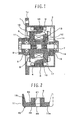
- Fig. 1 is a longitudinal sectional view of the vehicular alternator.
- a stator core 3 is held between a front housing 1 and a rear housing 2.
- the front housing 1, the rear housing 2, and the stator core 3 are fixed together by tightening screws and nuts (not shown) to apply a strong force in the direction in which the front housing 1 and the rear housing 2 grip the stator core 3 between them.
- the front housing 1 includes a flange 1a which is used to fix the alternator to a bracket provided on an engine block (not shown).
- the stator core 3 has a plurality of teeth formed along an entire inner periphery facing the rotor side, and stator coils 4 are wound over the teeth. Three-phase AC voltages are induced in the stator coils 4 with the rotation of magnetized rotor cores 11 and 14 (described later).
- a rotary shaft 5 is rotatably supported by the front housing 1 and the rear housing 2 through a bearing 6 provided in the front housing 1 and a bearing 7 provided in the rear housing 2.
- a pulley 8 for receiving torque from a driving source, i.e., an engine, is fastened to an end of the rotary shaft 5 on the same side as the front housing 1 by screwing a nut.
- a rotor core 11 is made up of a hollow cylindrical yoke 9 and a claw-equipped core 10 having a plurality (six in the illustrated example) of claws 15, which are integrally projected from an outer peripheral portion of the core 10 so as to serve as magnetic poles, the yoke 12 and the claw-equipped core 10 being integrated with each other by the method according to the present invention.
- a rotor core 14 is made up of a yoke 12 and a claw-equipped core 13 which are integrated with each other similarly to the rotor core 11.
- the claw-equipped core 10 and the claw-equipped core 13 are fixed to a substantially central area of the rotary shaft 5 to be held in mutually fixed state.
- the claws 15 and 16 of the claw-equipped cores 10 and 13 are arranged in interdigitated relation.
- the rotor cores 11 and 14 are fixed to the rotary shaft 5 by causing parts of the yokes 9 and 12 to flow into respective annular grooves formed in the rotary shaft 5 by plastic flow.
- a field coil 17 is wound over the yokes 9 and 12 of the rotor cores 11 and 14.
- a slip ring 18 is fastened to an end of the rotary shaft 5 on the side nearer to the rear housing 2 and is supplied with a current from the exterior through a brush 19.
- a current is supplied to the field coil 17 from the exterior, magnetic flux is generated in the rotor cores 11 and 14 and around the stator core 3 on the housing side, to thereby constitute a magnetic flux path as indicated by an arrow ⁇ in Fig. 1.
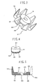
- Figs. 5 and 6 show one example of the claw-equipped core 10 according to the present invention.
- the claw-equipped core 10 has a base portion 10a substantially in the form of a starfish, and six claws 15 are projected from the base portion 10a in the axial direction of the rotary shaft 5 (i.e., the upward direction in Fig. 2) such that each claw 15 has a tapered shape.
- the claws 15 are not necessarily required to project exactly parallel to the rotary shaft 5, and the claws 15 may be inclined to some extent with respect to the rotary shaft 5 so long as they are projected substantially in the axial direction of the rotary shaft 5.
- a joining hole 23 in the form of a recessed hole is formed as a fitting portion substantially at a central position of one surface of the starfish-shaped base portion 10a on the side where the claws 15 are projected.
- the joining hole 23 has a diameter slightly larger than an outer diameter of the yoke 9.
- a core center hole 20 through which is inserted the rotary shaft 5 is formed substantially at a central position of the bottom of the joining hole 23 so as to penetrate the starfish-shaped base portion 10a up to the opposite side.
- the core central hole 20 is also utilized as a positioning hole when the yoke 9 is plastically joined to the claw-equipped core 10.
- Fig. 4 shows one example of the yoke 9 according to the present invention.
- the yoke 9 has a hollow cylindrical shape with a through-hole 21 formed at a center to penetrate thoroughly.
- the through-hole 21 is formed to be positioned in substantially continuous relation to the core central hole 20.
- the through-hole 21 also receives the rotary shaft 5 and is utilized as a positioning hole when the yoke 9 is plastically joined to the claw-equipped core 10. Further, as shown in enlarged views of Figs.
- annular grooves 40 each having an almost triangular axial cross-section, are preferably formed in an outer diameter portion of the yoke 9 near one end thereof, which portion is to be joined to the claw-equipped core 10, thus providing substantially saw-toothed annular grooves 40.
- Figs. 2 and 3 show one example of the rotor core 11 made up of the claw-equipped core 10 and the yoke 9 according to the present invention.
- the end of the yoke 9 on the side where the annular grooves 40 are formed to the joining hole 23 of the claw-equipped core 10 and locally pressing an outer peripheral edge of the joining hole 23, the yoke 9 and the claw-equipped core 10 are plastically joined to each other while a pressing mark 22 is left as shown.
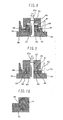
- FIG. 7 the core central hole 20 formed in the claw-equipped core 10 is inserted through a column-like mandrel 30 fixed on a plate 29 such that the claw-equipped core 10 is held in an illustrated state. Thereafter, an end 42 of the yoke 9 on the side where the annular grooves 40 are formed is fitted to the joining hole 23 of the claw-equipped core 10. Portions of the claw-equipped core 10 and the yoke 9 fitted to each other are desirably dimensioned to allow clearance fit when the end of the yoke 9 is fitted to the joining hole 23 of the claw-equipped core 10. The fitted portions of the claw-equipped core 10 and the yoke 9 are as shown in an enlarged longitudinal sectional view of Fig. 10 or 11.
- a punch 27 having a mandrel insertion hole 27a formed to penetrate therethrough is fitted over the mandrel 30, thus coming into a state just before the start of pressing. Then, by pressing the punch 27 to drive it in the direction of an arrow by a press ram (not shown), an annular boss 28 of the punch 27 presses a portion of an end surface 24 of the claw-equipped core 10 which is positioned near the joining hole 23, desirably the outer peripheral edge of the joining hole 23.
- Fig. 9 shows a state where the pressing is completed.
- a pressing force of the punch 27 is set to apply a load for generating stresses sufficient to plastically deform the material of the claw-equipped core 10 so that the material near the joining hole 23 is deformed in the axial direction of the rotary shaft 5 to flow into the annular grooves 40 by plastic flow for joining the yoke 9 and the claw-equipped core 10 together.
- the annular grooves 40 have the triangular cross-sections, the sloped surfaces enable the material to flow more easily by plastic flow. Therefore, compressive stresses can also be more easily generated.
- the fitted portions after being subjected to the plastic flow in such a manner are as shown in the enlarged longitudinal sectional view of Fig. 11.
- the annular grooves 40 are not necessarily required to be formed in the yoke 9 and a part of the claw-equipped core 10 may be pressed and joined to an outer periphery of the yoke 9 just by plastic flow.
- a boss width W of the annular boss 28 of the punch 27 and a pressing depth H, shown in Fig. 17, are desirably set in conformity with the shape of the annular grooves 40 for the reason as follows. If the boss width W and the pressing depth H are too large, the material is caused to flow in amount in excess of the amount allowable to flow into the annular grooves 40 and the claw-equipped core 10 is deformed, thus resulting in deterioration of joining accuracy. The joining strength is increased with an increase in a depth K of the annular grooves 40.
- the annular grooves 40 are shaped to have the groove depth K of about 0.3 - 0.5 mm, a groove angle ⁇ of about 60° - 90°, and a groove width K' of about 0.6 - 2 mm. Further, the boss width W is set to about 0.5 - 1.6 mm and the pressing depth H is set to about 0.4 - 1 mm.
- the cross-sectional shape of the annular grooves 40 of the yoke 9 is not necessarily required to be triangular as shown in Fig. 14. More specifically, the annular grooves 40 can be replaced with circularly curved grooves, i.e., grooves 44 having substantially semicircular curved surfaces in an axial cross-section as shown in Fig. 15, or with a single groove 45 having a trapezoidal shape as shown in Fig. 16.
- the substantially semicircular grooves 44 are easier to machine it and enable the plastic flow to be more easily caused along their inner curved surfaces.
- the trapezoidal groove 45 is even easier to machine it and is suitable for manufacturing a product at an inexpensive cost.
- the substantially semicircular groove is suitably used for a yoke having a relatively large diameter.
- the number of the annular grooves is not limited to a particular number and it may be one or plural.
- the grooves may be spaced from each other by a certain distance or may be formed in a spiral shape. Further, by machining the annular grooves by cold rolling, the strength of groove portions is increased by work hardening and a degree of deformation caused during the joining process is reduced, thus resulting in higher joining strength.
- the groove inner surface is formed to have a roughly projected and recessed shape by knurling as shown in Figs. 12 and 13, a larger degree of the rolling work is obtained so as to provide higher work hardening.
- the knurling of the groove inner surface is effective in increasing the groove strength and the joining strength.
- the press ram (not shown) is ascended to move the punch 27 away from the yoke 9, and the rotor core 11 including the yoke 9 and the claw-equipped core 10 integrally joined to each other is removed from the plate 29 and the mandrel 30.
- the rotor core 11 is thereby completed.
- the claw-equipped core 10 and the yoke 9 are integrally joined to each other in coaxial relation with the aid of the mandrel 30, they have superior coaxial accuracy. Therefore, when the thus-obtained rotor core 11 is fastened to the rotary shaft 5, balance required as a rotating member can be easily established.
- the material caused to flow into the annular grooves 40 by plastic flow develops the so-called spike effect which makes the contact surfaces of the claw-equipped core 10 and the yoke 9 harder to separate from each other.
- the annular grooves 40 have the knurled inner surfaces, the resistance against forces in the rotating direction as well can be further increased.
- the rotor core 14 is manufactured in the same manner as the rotor core 11.
- the rotor cores 11 and 14 are fixed to knurled annular grooves formed in the rotary shaft 5 by a similar method to the above-described method used for joining the yokes 9, 12 and the claw-equipped cores 10, 13 such that the yokes 9 and 12 are contacted with each other and the rotor cores 11 and 14 are held fixed in both the axial direction and the rotating direction by plastic flow.
- the claw-equipped core 10 and the yoke 9 can be manufactured respectively at inexpensive costs, for example, by cold-forging of a blank which is obtained by punching a low-carbon steel plate into a starfish-like shape, and by cold-forging of a round rod under compression.
- the claw-equipped core 10 and the yoke 9 may be manufactured by cutting.
- the rotor cores 11 and 14 are obtained by manufacturing the yokes 9, 12 and the claw-equipped cores 10, 13 as separate members, and joining the paired members to each other by plastic flow. In comparison with the case where the yoke and the claw-equipped core are integrally formed as one component, therefore, the scale of a production facility including a cold-forging pressing step, an intermediate annealing step, a lubricating step, etc. is not so increased and the rotor core can be inexpensively produced in a relatively small-scaled facility.
- Hot forging is also usable instead of cold forging, but the hot forging is disadvantageous in deteriorating accuracy, requiring more complicated steps because of the necessity of ensuring accuracy in shape by additional cutting or cold forging, and contradicting with the aspect of energy saving. Therefore, the cold forging is more desirable than the hot forging.
- the yokes 9 and 12 and the claw-equipped cores 10 and 13 can be positively avoided from separating from each other at their joined portions under influences of centrifugal forces acting on the claw-equipped cores 10 and 13 even when the rotor cores 11 and 14 are rotated at high speed with the rotation of the engine. Accordingly, it is possible to prevent an increase of magnetic resistance and deterioration of magnetic performance.
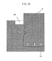
- the material of the claw-equipped core 10 is caused to flow radially inward toward the yoke 9 as indicated by arrows in Fig. 20, and the yoke 9 and the claw-equipped core 10 can be jointed to each other in a state where radial compressive stresses are held therein. Also, since the material of the claw-equipped core 10 subjected to the plastic flow is more apt to flow in the axial direction, component forces acting from the annular grooves 40 toward the bottom surface 25 of the joining hole 23 become larger, whereby stresses acting to closely contact the yoke 9 and the claw-equipped core 10 with each other in the axial direction can also be held therein.
- the yoke 9 and the claw-equipped core 10 can be maintained in a closely contacted state, and a gap between the claw-equipped core 10 and the stator core 3 can be set to a minimum value so that they are positioned as close as possible.
- magnetic characteristics are improved, an output is increased, and magnetic noise is reduced.
- the yoke 9 and the claw-equipped core 10 can be joined to each other in a state where larger axial compressive stresses act between the bottom surface of the joining hole 23 and the end of the yoke 9.
- the material of the claw-equipped core 10 is caused to fill into the annular grooves 40 when the claw-equipped core 10 is subjected to plastic flow.
- the material of the claw-equipped core 10 is not just pressed against the yoke 9, but it is caused to bite into the yoke 9, whereby the yoke 9 and the claw-equipped core 10 can be joined to each other with higher reliability.
- the annular grooves 40 are knurled by cold forging, a portion around the annular grooves 40 is hardened so that the material of the claw-equipped core 10 can more easily bite into the yoke 9.
- the material of the claw-equipped core 10 is able to more easily bite into the yoke 9.
- the number of the claws of the claw-equipped core 10 may be eight instead of six. Namely, the number and the shape of the claws is a matter of choice in design. When the number of the claws is increased, the number of magnetic flux paths is also increased and the efficiency of power generation is improved correspondingly. On the other hand, the strength of each claw is reduced. Therefore, the number of the claws is required to be set to an appropriate number.
- each yoke 9 and 12 are each formed into a cylindrical shape in the above-described embodiment, the yoke is not always required to have a cylindrical shape so long as it is tubular. Depending on applications, each yoke can be formed into a polygonal shape, a partly cutout shape, or any other suitable shape.
- the fitting portion is constituted by the joining hole 23 formed in the claw-equipped core 10 in the above-described embodiment
- plastic flow may be performed in such a state that a joining hole is formed in the yoke 9 and a projection formed on the claw-equipped core 10 is fitted to the joining hole of the yoke.
- the joining hole 23 is not always required to be a recess directly formed in the claw-equipped core 10 or the yoke 9.
- the joining hole 23 may be given as a recess formed by raising a portion around the joining hole 23.
- the pressing mark 22 is formed in the outer peripheral edge of the joining hole 23 in the above-described embodiment, the pressing mark 22 is not always required to be positioned just at the edge of the joining hole 23 and it may be formed at a certain distance away from the edge the joining hole 23. When a portion around the joining hole 23 is in the protruded form, the pressing mark 22 may be positioned in a side surface of the protruded portion around the joining hole 23.
- the pressing mark 22 is formed in an annular shape in the above-described embodiment, the pressing mark is not always required to have an annular shape and it may be formed at plural positions in the circumferential direction. When the pressing mark is formed at plural positions, those marks are preferably positioned at equal intervals in the circumferential direction.
- the groove is not always required to have an annular shape and it may be formed at plural positions in the circumferential direction.
- those grooves are preferably positioned at equal intervals in the circumferential direction.
- the groove can be formed in the claw-equipped core 10.
- annular groove 40 is subjected to cold rolling for work hardening in the above-described embodiment, any other suitable method can also be used so long as the method is able to harden the material forming the annular groove.
- cutting can be used instead.
- the yoke is required to be annealed in the case of causing the material of the yoke to flow by plastic flow.
- plastic flow is employed in the above-described embodiment as means for mechanically integrating the claw-equipped core 10 and the yoke 9, they may be mechanically integrated with each other by any other suitable means, such as friction welding.
- the joining hole 23 is formed as a hole in the form of a recess equipped with the bottom in the above-described embodiment, the joining hole may be formed, for example, as a hole penetrating through the claw-equipped core 10 at the same diameter as that of a base portion of the yoke 9.
Landscapes
- Engineering & Computer Science (AREA)
- Mechanical Engineering (AREA)
- Power Engineering (AREA)
- Manufacturing & Machinery (AREA)
- Iron Core Of Rotating Electric Machines (AREA)
- Synchronous Machinery (AREA)
- Manufacture Of Motors, Generators (AREA)
Applications Claiming Priority (1)
| Application Number | Priority Date | Filing Date | Title |
|---|---|---|---|
| JP2005355533A JP4856940B2 (ja) | 2005-12-09 | 2005-12-09 | 回転電機およびその製造方法 |
Publications (2)
| Publication Number | Publication Date |
|---|---|
| EP1796244A2 true EP1796244A2 (de) | 2007-06-13 |
| EP1796244A3 EP1796244A3 (de) | 2015-04-01 |
Family
ID=37857105
Family Applications (1)
| Application Number | Title | Priority Date | Filing Date |
|---|---|---|---|
| EP06025371.3A Withdrawn EP1796244A3 (de) | 2005-12-09 | 2006-12-07 | Rotierende elektrische Maschine für einen Wechselstromgenerator, und Verfahren zur Herstellung eines Rotorkerns für diese Maschine |
Country Status (4)
| Country | Link |
|---|---|
| US (1) | US7737602B2 (de) |
| EP (1) | EP1796244A3 (de) |
| JP (1) | JP4856940B2 (de) |
| CN (1) | CN1980006B (de) |
Cited By (1)
| Publication number | Priority date | Publication date | Assignee | Title |
|---|---|---|---|---|
| FR3036550A1 (fr) * | 2015-05-22 | 2016-11-25 | Valeo Systemes De Controle Moteur | Procede de blocage de deux pieces |
Families Citing this family (13)
| Publication number | Priority date | Publication date | Assignee | Title |
|---|---|---|---|---|
| JP2008092673A (ja) * | 2006-10-02 | 2008-04-17 | Denso Corp | 車両用交流発電機の回転子 |
| JP5268553B2 (ja) * | 2008-10-15 | 2013-08-21 | 日立オートモティブシステムズ株式会社 | 車両用回転電機 |
| JPWO2011121770A1 (ja) * | 2010-03-31 | 2013-07-04 | 株式会社日立製作所 | 車両用交流発電機 |
| JP5397396B2 (ja) * | 2011-03-02 | 2014-01-22 | 株式会社デンソー | 回転電機の回転子鉄心の製造方法 |
| DE102012021042A1 (de) * | 2011-10-31 | 2013-05-02 | Asmo Co., Ltd. | Rotor und Motor |
| DE102012021041A1 (de) | 2011-10-31 | 2013-05-02 | Asmo Co., Ltd. | Rotor und Motor |
| DE102012021109B4 (de) | 2011-10-31 | 2023-04-27 | Denso Corporation | Rotor und Motor |
| DE102012021049A1 (de) | 2011-10-31 | 2013-05-02 | Asmo Co., Ltd. | Rotor und Motor |
| DE102012021048A1 (de) | 2011-10-31 | 2013-05-02 | Asmo Co., Ltd. | Rotor und Motor |
| FR3019399B1 (fr) * | 2014-03-25 | 2016-03-11 | Valeo Equip Electr Moteur | Roue polaire forgee pour alternateur de vehicule automobile muni d'aimants permanents interpolaires |
| CN103997142A (zh) * | 2014-05-07 | 2014-08-20 | 江苏航天动力机电有限公司 | 电励磁双凸极电机转子 |
| FR3040835B1 (fr) * | 2015-09-03 | 2017-08-25 | Valeo Equip Electr Moteur | Machine electrique tournante comportant un arbre a diametres etages et procede d'assemblage d'une telle machine |
| DE102018116988A1 (de) * | 2018-07-13 | 2020-01-16 | Nidec Corporation | Elektromotor mit einstückigem Innenläufer-Rotorkern |
Family Cites Families (26)
| Publication number | Priority date | Publication date | Assignee | Title |
|---|---|---|---|---|
| US2795715A (en) * | 1954-11-16 | 1957-06-11 | Leece Neville Co | Rotor construction for electrical machines |
| US3242364A (en) * | 1960-12-05 | 1966-03-22 | Bendix Corp | Electrical apparatus |
| US3529856A (en) * | 1969-01-08 | 1970-09-22 | Dumont Aviat Associates | Coupling and method of forming same |
| US3614593A (en) * | 1970-05-06 | 1971-10-19 | Motorola Inc | Rotary transformer for alternator |
| US4019799A (en) * | 1976-02-11 | 1977-04-26 | The Bendix Corporation | Electrical connector |
| DE2811323A1 (de) * | 1978-03-16 | 1979-09-27 | Bosch Gmbh Robert | Laeufer fuer elektrische maschine |
| JPS55117459A (en) * | 1979-03-05 | 1980-09-09 | Hitachi Ltd | Rotor of rotating-electric machine and its manufacturing method |
| JPS567477A (en) * | 1979-06-29 | 1981-01-26 | Mitsubishi Electric Corp | Amplification switching semiconductor device |
| JPS5698349A (en) * | 1980-01-07 | 1981-08-07 | Hitachi Ltd | Rotor of rotary electric machine and manufacture thereof |
| JPS57148552A (en) * | 1981-03-06 | 1982-09-13 | Hitachi Ltd | Coupling method for rotor of magneto generator |
| JPS58130756A (ja) * | 1982-01-27 | 1983-08-04 | Hitachi Ltd | 交流発電機の回転子の製造方法 |
| NL8400780A (nl) * | 1984-03-12 | 1985-10-01 | Philips Nv | Rotor voor een electrische machine. |
| JPS6168653A (ja) * | 1984-09-12 | 1986-04-09 | Fujitsu Ltd | 領域検索制御方式 |
| US4703987A (en) * | 1985-09-27 | 1987-11-03 | Amphenol Corporation | Apparatus and method for retaining an insert in an electrical connector |
| US4746240A (en) * | 1987-04-01 | 1988-05-24 | General Motors Corporation | Self crimping connection for inner and outer members and method of assembling the same |
| DE3931442A1 (de) * | 1989-09-21 | 1991-04-04 | Bosch Gmbh Robert | Laeufer fuer elektrische maschinen und verfahren zu seiner herstellung |
| US5177391A (en) * | 1990-03-14 | 1993-01-05 | Nippondenso Co., Ltd. | Power generating apparatus |
| US5457588A (en) * | 1992-09-22 | 1995-10-10 | Nippon Densan Corporation | Low profile hydrodynamic motor having minimum leakage properties |
| JP3429016B2 (ja) * | 1992-12-04 | 2003-07-22 | 株式会社デンソー | 爪付界磁鉄心及びその製造方法 |
| DE19642784A1 (de) * | 1996-10-17 | 1998-04-23 | Bosch Gmbh Robert | Klauenpolgenerator |
| JP2001054268A (ja) * | 1999-08-06 | 2001-02-23 | Hitachi Ltd | ディスク装置のシャフトとハブの結合方法とその結合体 |
| JP3974315B2 (ja) * | 2000-07-25 | 2007-09-12 | 三菱電機株式会社 | 交流発電機 |
| JP2004072852A (ja) * | 2002-08-05 | 2004-03-04 | Denso Corp | 回転電機の回転子およびその製造方法 |
| JP3868361B2 (ja) * | 2002-10-04 | 2007-01-17 | 株式会社日立製作所 | 塑性流動結合体とその結合方法 |
| JP3938090B2 (ja) * | 2003-04-16 | 2007-06-27 | 株式会社日立製作所 | ローターコアの製造方法 |
| CN101421129A (zh) * | 2003-11-24 | 2009-04-29 | 雅各布斯车辆系统公司 | 电磁减速器系统和方法 |
-
2005
- 2005-12-09 JP JP2005355533A patent/JP4856940B2/ja not_active Expired - Fee Related
-
2006
- 2006-12-06 CN CN2006101641639A patent/CN1980006B/zh not_active Expired - Fee Related
- 2006-12-07 EP EP06025371.3A patent/EP1796244A3/de not_active Withdrawn
- 2006-12-07 US US11/634,977 patent/US7737602B2/en not_active Expired - Fee Related
Cited By (2)
| Publication number | Priority date | Publication date | Assignee | Title |
|---|---|---|---|---|
| FR3036550A1 (fr) * | 2015-05-22 | 2016-11-25 | Valeo Systemes De Controle Moteur | Procede de blocage de deux pieces |
| WO2016189226A1 (fr) * | 2015-05-22 | 2016-12-01 | Valeo Systemes De Controle Moteur | Procédé de blocage de deux pièces |
Also Published As
| Publication number | Publication date |
|---|---|
| JP2007159378A (ja) | 2007-06-21 |
| CN1980006B (zh) | 2010-05-19 |
| JP4856940B2 (ja) | 2012-01-18 |
| US7737602B2 (en) | 2010-06-15 |
| EP1796244A3 (de) | 2015-04-01 |
| CN1980006A (zh) | 2007-06-13 |
| US20070132337A1 (en) | 2007-06-14 |
Similar Documents
| Publication | Publication Date | Title |
|---|---|---|
| US7737602B2 (en) | Rotating electrical machine or alternator and method of manufacturing rotor core used in the same | |
| CN101517862B (zh) | 爪形极转子轴、配备有这种轴的爪形极转子和配备有这种转子的旋转电机 | |
| US4339873A (en) | Method of making rotor of rotary machines | |
| US10944306B2 (en) | Rotary electric rotor and method of manufacturing rotary electric rotor | |
| CA2064627C (en) | Pulley with integral fastener and spacer | |
| EP2582015A1 (de) | Rotor für eine elektrische drehmaschine | |
| CN103219812B (zh) | 具有分割式铁芯的电动机的转子及其制造方法 | |
| US4792713A (en) | Lamination to rotor shaft retention method utilizing spring pins | |
| JP2005520999A (ja) | 自動車のオルタネータのプーリを含む組み立て体及びその組み立て方法 | |
| KR20070116054A (ko) | 샤프트와 자극편 사이에 개재된 중간 슬리브를 포함하는회전식 전기 기계 및 로터 제조 방법 | |
| JP2011254663A (ja) | 回転電機用ロータの製造方法及び回転電機用シャフト素材 | |
| CN101189780B (zh) | 旋转电机的电枢及其制造方法 | |
| GB2029743A (en) | Flywheel magneto rotor and method of manufacture thereof | |
| US11336158B2 (en) | Manufacturing method of core of rotating electrical machine, and core of rotating electrical machine | |
| JP7214577B2 (ja) | 始動発電機及び始動発電機の製造方法 | |
| US4934042A (en) | Lamination to rotor shaft retention method utilizing spring pins | |
| JP5445523B2 (ja) | 回転電機 | |
| CN100333854C (zh) | 轴及其成型装置 | |
| JP3727476B2 (ja) | 回転電機の固定子 | |
| JP2000329214A (ja) | 組立カムシャフトおよびその製造方法 | |
| JP2017204912A (ja) | 回転電機の固定子 | |
| EP1467122A1 (de) | Verfahren zur Herstellung einer Motorschwungscheibe und eine derartig hergestellte Motorschwungscheibe. | |
| JP6355268B2 (ja) | 嵌合構造及び被嵌合部材の製造方法 | |
| JPS6059816B2 (ja) | 車両用交流発電機の回転軸 | |
| JP2004299666A (ja) | 車輪用軸受装置 |
Legal Events
| Date | Code | Title | Description |
|---|---|---|---|
| PUAI | Public reference made under article 153(3) epc to a published international application that has entered the european phase |
Free format text: ORIGINAL CODE: 0009012 |
|
| AK | Designated contracting states |
Kind code of ref document: A2 Designated state(s): AT BE BG CH CY CZ DE DK EE ES FI FR GB GR HU IE IS IT LI LT LU LV MC NL PL PT RO SE SI SK TR |
|
| AX | Request for extension of the european patent |
Extension state: AL BA HR MK YU |
|
| 17P | Request for examination filed |
Effective date: 20090618 |
|
| PUAL | Search report despatched |
Free format text: ORIGINAL CODE: 0009013 |
|
| AK | Designated contracting states |
Kind code of ref document: A3 Designated state(s): AT BE BG CH CY CZ DE DK EE ES FI FR GB GR HU IE IS IT LI LT LU LV MC NL PL PT RO SE SI SK TR |
|
| AX | Request for extension of the european patent |
Extension state: AL BA HR MK RS |
|
| RIC1 | Information provided on ipc code assigned before grant |
Ipc: H02K 1/24 20060101AFI20150225BHEP Ipc: H02K 5/08 20060101ALI20150225BHEP Ipc: H02K 15/02 20060101ALI20150225BHEP Ipc: B21K 1/28 20060101ALI20150225BHEP |
|
| STAA | Information on the status of an ep patent application or granted ep patent |
Free format text: STATUS: THE APPLICATION HAS BEEN WITHDRAWN |
|
| 18W | Application withdrawn |
Effective date: 20150317 |