EP1796244A2 - Rotating electrical machine for alternator and method of manufacturing rotor core used in the same - Google Patents
Rotating electrical machine for alternator and method of manufacturing rotor core used in the same Download PDFInfo
- Publication number
- EP1796244A2 EP1796244A2 EP06025371A EP06025371A EP1796244A2 EP 1796244 A2 EP1796244 A2 EP 1796244A2 EP 06025371 A EP06025371 A EP 06025371A EP 06025371 A EP06025371 A EP 06025371A EP 1796244 A2 EP1796244 A2 EP 1796244A2
- Authority
- EP
- European Patent Office
- Prior art keywords
- claw
- yoke
- core
- equipped core
- electrical machine
- Prior art date
- Legal status (The legal status is an assumption and is not a legal conclusion. Google has not performed a legal analysis and makes no representation as to the accuracy of the status listed.)
- Withdrawn
Links
Images


Classifications
-
- H—ELECTRICITY
- H02—GENERATION; CONVERSION OR DISTRIBUTION OF ELECTRIC POWER
- H02K—DYNAMO-ELECTRIC MACHINES
- H02K15/00—Methods or apparatus specially adapted for manufacturing, assembling, maintaining or repairing of dynamo-electric machines
- H02K15/02—Methods or apparatus specially adapted for manufacturing, assembling, maintaining or repairing of dynamo-electric machines of stator or rotor bodies
- H02K15/022—Methods or apparatus specially adapted for manufacturing, assembling, maintaining or repairing of dynamo-electric machines of stator or rotor bodies with salient poles or claw-shaped poles
-
- B—PERFORMING OPERATIONS; TRANSPORTING
- B21—MECHANICAL METAL-WORKING WITHOUT ESSENTIALLY REMOVING MATERIAL; PUNCHING METAL
- B21K—MAKING FORGED OR PRESSED METAL PRODUCTS, e.g. HORSE-SHOES, RIVETS, BOLTS OR WHEELS
- B21K1/00—Making machine elements
- B21K1/28—Making machine elements wheels; discs
-
- B—PERFORMING OPERATIONS; TRANSPORTING
- B21—MECHANICAL METAL-WORKING WITHOUT ESSENTIALLY REMOVING MATERIAL; PUNCHING METAL
- B21K—MAKING FORGED OR PRESSED METAL PRODUCTS, e.g. HORSE-SHOES, RIVETS, BOLTS OR WHEELS
- B21K25/00—Uniting components to form integral members, e.g. turbine wheels and shafts, caulks with inserts, with or without shaping of the components
-
- H—ELECTRICITY
- H02—GENERATION; CONVERSION OR DISTRIBUTION OF ELECTRIC POWER
- H02K—DYNAMO-ELECTRIC MACHINES
- H02K1/00—Details of the magnetic circuit
- H02K1/06—Details of the magnetic circuit characterised by the shape, form or construction
- H02K1/22—Rotating parts of the magnetic circuit
- H02K1/24—Rotor cores with salient poles ; Variable reluctance rotors
- H02K1/243—Rotor cores with salient poles ; Variable reluctance rotors of the claw-pole type
-
- H—ELECTRICITY
- H02—GENERATION; CONVERSION OR DISTRIBUTION OF ELECTRIC POWER
- H02K—DYNAMO-ELECTRIC MACHINES
- H02K5/00—Casings; Enclosures; Supports
- H02K5/04—Casings or enclosures characterised by the shape, form or construction thereof
- H02K5/08—Insulating casings
-
- Y—GENERAL TAGGING OF NEW TECHNOLOGICAL DEVELOPMENTS; GENERAL TAGGING OF CROSS-SECTIONAL TECHNOLOGIES SPANNING OVER SEVERAL SECTIONS OF THE IPC; TECHNICAL SUBJECTS COVERED BY FORMER USPC CROSS-REFERENCE ART COLLECTIONS [XRACs] AND DIGESTS
- Y10—TECHNICAL SUBJECTS COVERED BY FORMER USPC
- Y10T—TECHNICAL SUBJECTS COVERED BY FORMER US CLASSIFICATION
- Y10T29/00—Metal working
- Y10T29/49—Method of mechanical manufacture
- Y10T29/49002—Electrical device making
- Y10T29/49009—Dynamoelectric machine
- Y10T29/49012—Rotor
Definitions
- plate-like rotor cores are disposed at opposite ends of a cylindrical yoke which is disposed in the inner peripheral side, and a plurality of claws are axially projected from outer peripheries of the rotor cores in alternately interdigitated relation.
- a shaft is inserted within the yoke.
- Patent Document 1 JP-B-61-000979 discloses a rotor core structure in which claw-equipped cores and a yoke are constituted as separate parts, and these separates parts are individually fastened to a shaft to constitute an integral assembly for the purpose of avoiding a production facility from increasing in scale corresponding to an increase of the component size.
- An object of the present invention is to provide a rotating electrical machine or an alternator in which claws of a rotor core are hard to open in the radial direction even under the action of a centrifugal force during rotation and an air gap between the claws and a stator core can be reduced, and a method of manufacturing a rotor core used in the rotating electrical machine or the alternator.
- the present invention is featured in that a yoke is joined to a claw-equipped core by plastic flow.
- the present invention is featured in that the claw-equipped core and the yoke are mechanically integrally joined to each other.
- the present invention is featured in comprising the steps of forming a fitting portion in the claw-equipped core, fitting the yoke to the fitting portion, and axially pressing a part of the claw-equipped core around the fitting portion to be plastically deformed, thereby joining the claw-equipped core and the yoke to each other.
- claws of the rotor core are hard to open in the radial direction even under the action of a centrifugal force during rotation and an air gap between the claws and a stator core can be reduced. As a result, magnetic performance can be ensured at a sufficient level.
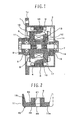
- Fig. 1 is a longitudinal sectional view of the vehicular alternator.
- a stator core 3 is held between a front housing 1 and a rear housing 2.
- the front housing 1, the rear housing 2, and the stator core 3 are fixed together by tightening screws and nuts (not shown) to apply a strong force in the direction in which the front housing 1 and the rear housing 2 grip the stator core 3 between them.
- the front housing 1 includes a flange 1a which is used to fix the alternator to a bracket provided on an engine block (not shown).
- the stator core 3 has a plurality of teeth formed along an entire inner periphery facing the rotor side, and stator coils 4 are wound over the teeth. Three-phase AC voltages are induced in the stator coils 4 with the rotation of magnetized rotor cores 11 and 14 (described later).
- a rotary shaft 5 is rotatably supported by the front housing 1 and the rear housing 2 through a bearing 6 provided in the front housing 1 and a bearing 7 provided in the rear housing 2.
- a pulley 8 for receiving torque from a driving source, i.e., an engine, is fastened to an end of the rotary shaft 5 on the same side as the front housing 1 by screwing a nut.
- a rotor core 11 is made up of a hollow cylindrical yoke 9 and a claw-equipped core 10 having a plurality (six in the illustrated example) of claws 15, which are integrally projected from an outer peripheral portion of the core 10 so as to serve as magnetic poles, the yoke 12 and the claw-equipped core 10 being integrated with each other by the method according to the present invention.
- a rotor core 14 is made up of a yoke 12 and a claw-equipped core 13 which are integrated with each other similarly to the rotor core 11.
- the claw-equipped core 10 and the claw-equipped core 13 are fixed to a substantially central area of the rotary shaft 5 to be held in mutually fixed state.
- the claws 15 and 16 of the claw-equipped cores 10 and 13 are arranged in interdigitated relation.
- the rotor cores 11 and 14 are fixed to the rotary shaft 5 by causing parts of the yokes 9 and 12 to flow into respective annular grooves formed in the rotary shaft 5 by plastic flow.
- a field coil 17 is wound over the yokes 9 and 12 of the rotor cores 11 and 14.
- a slip ring 18 is fastened to an end of the rotary shaft 5 on the side nearer to the rear housing 2 and is supplied with a current from the exterior through a brush 19.
- a current is supplied to the field coil 17 from the exterior, magnetic flux is generated in the rotor cores 11 and 14 and around the stator core 3 on the housing side, to thereby constitute a magnetic flux path as indicated by an arrow ⁇ in Fig. 1.
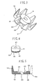
- Figs. 5 and 6 show one example of the claw-equipped core 10 according to the present invention.
- the claw-equipped core 10 has a base portion 10a substantially in the form of a starfish, and six claws 15 are projected from the base portion 10a in the axial direction of the rotary shaft 5 (i.e., the upward direction in Fig. 2) such that each claw 15 has a tapered shape.
- the claws 15 are not necessarily required to project exactly parallel to the rotary shaft 5, and the claws 15 may be inclined to some extent with respect to the rotary shaft 5 so long as they are projected substantially in the axial direction of the rotary shaft 5.
- a joining hole 23 in the form of a recessed hole is formed as a fitting portion substantially at a central position of one surface of the starfish-shaped base portion 10a on the side where the claws 15 are projected.
- the joining hole 23 has a diameter slightly larger than an outer diameter of the yoke 9.
- a core center hole 20 through which is inserted the rotary shaft 5 is formed substantially at a central position of the bottom of the joining hole 23 so as to penetrate the starfish-shaped base portion 10a up to the opposite side.
- the core central hole 20 is also utilized as a positioning hole when the yoke 9 is plastically joined to the claw-equipped core 10.
- Fig. 4 shows one example of the yoke 9 according to the present invention.
- the yoke 9 has a hollow cylindrical shape with a through-hole 21 formed at a center to penetrate thoroughly.
- the through-hole 21 is formed to be positioned in substantially continuous relation to the core central hole 20.
- the through-hole 21 also receives the rotary shaft 5 and is utilized as a positioning hole when the yoke 9 is plastically joined to the claw-equipped core 10. Further, as shown in enlarged views of Figs.
- annular grooves 40 each having an almost triangular axial cross-section, are preferably formed in an outer diameter portion of the yoke 9 near one end thereof, which portion is to be joined to the claw-equipped core 10, thus providing substantially saw-toothed annular grooves 40.
- Figs. 2 and 3 show one example of the rotor core 11 made up of the claw-equipped core 10 and the yoke 9 according to the present invention.
- the end of the yoke 9 on the side where the annular grooves 40 are formed to the joining hole 23 of the claw-equipped core 10 and locally pressing an outer peripheral edge of the joining hole 23, the yoke 9 and the claw-equipped core 10 are plastically joined to each other while a pressing mark 22 is left as shown.
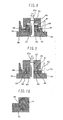
- FIG. 7 the core central hole 20 formed in the claw-equipped core 10 is inserted through a column-like mandrel 30 fixed on a plate 29 such that the claw-equipped core 10 is held in an illustrated state. Thereafter, an end 42 of the yoke 9 on the side where the annular grooves 40 are formed is fitted to the joining hole 23 of the claw-equipped core 10. Portions of the claw-equipped core 10 and the yoke 9 fitted to each other are desirably dimensioned to allow clearance fit when the end of the yoke 9 is fitted to the joining hole 23 of the claw-equipped core 10. The fitted portions of the claw-equipped core 10 and the yoke 9 are as shown in an enlarged longitudinal sectional view of Fig. 10 or 11.
- a punch 27 having a mandrel insertion hole 27a formed to penetrate therethrough is fitted over the mandrel 30, thus coming into a state just before the start of pressing. Then, by pressing the punch 27 to drive it in the direction of an arrow by a press ram (not shown), an annular boss 28 of the punch 27 presses a portion of an end surface 24 of the claw-equipped core 10 which is positioned near the joining hole 23, desirably the outer peripheral edge of the joining hole 23.
- Fig. 9 shows a state where the pressing is completed.
- a pressing force of the punch 27 is set to apply a load for generating stresses sufficient to plastically deform the material of the claw-equipped core 10 so that the material near the joining hole 23 is deformed in the axial direction of the rotary shaft 5 to flow into the annular grooves 40 by plastic flow for joining the yoke 9 and the claw-equipped core 10 together.
- the annular grooves 40 have the triangular cross-sections, the sloped surfaces enable the material to flow more easily by plastic flow. Therefore, compressive stresses can also be more easily generated.
- the fitted portions after being subjected to the plastic flow in such a manner are as shown in the enlarged longitudinal sectional view of Fig. 11.
- the annular grooves 40 are not necessarily required to be formed in the yoke 9 and a part of the claw-equipped core 10 may be pressed and joined to an outer periphery of the yoke 9 just by plastic flow.
- a boss width W of the annular boss 28 of the punch 27 and a pressing depth H, shown in Fig. 17, are desirably set in conformity with the shape of the annular grooves 40 for the reason as follows. If the boss width W and the pressing depth H are too large, the material is caused to flow in amount in excess of the amount allowable to flow into the annular grooves 40 and the claw-equipped core 10 is deformed, thus resulting in deterioration of joining accuracy. The joining strength is increased with an increase in a depth K of the annular grooves 40.
- the annular grooves 40 are shaped to have the groove depth K of about 0.3 - 0.5 mm, a groove angle ⁇ of about 60° - 90°, and a groove width K' of about 0.6 - 2 mm. Further, the boss width W is set to about 0.5 - 1.6 mm and the pressing depth H is set to about 0.4 - 1 mm.
- the cross-sectional shape of the annular grooves 40 of the yoke 9 is not necessarily required to be triangular as shown in Fig. 14. More specifically, the annular grooves 40 can be replaced with circularly curved grooves, i.e., grooves 44 having substantially semicircular curved surfaces in an axial cross-section as shown in Fig. 15, or with a single groove 45 having a trapezoidal shape as shown in Fig. 16.
- the substantially semicircular grooves 44 are easier to machine it and enable the plastic flow to be more easily caused along their inner curved surfaces.
- the trapezoidal groove 45 is even easier to machine it and is suitable for manufacturing a product at an inexpensive cost.
- the substantially semicircular groove is suitably used for a yoke having a relatively large diameter.
- the number of the annular grooves is not limited to a particular number and it may be one or plural.
- the grooves may be spaced from each other by a certain distance or may be formed in a spiral shape. Further, by machining the annular grooves by cold rolling, the strength of groove portions is increased by work hardening and a degree of deformation caused during the joining process is reduced, thus resulting in higher joining strength.
- the groove inner surface is formed to have a roughly projected and recessed shape by knurling as shown in Figs. 12 and 13, a larger degree of the rolling work is obtained so as to provide higher work hardening.
- the knurling of the groove inner surface is effective in increasing the groove strength and the joining strength.
- the press ram (not shown) is ascended to move the punch 27 away from the yoke 9, and the rotor core 11 including the yoke 9 and the claw-equipped core 10 integrally joined to each other is removed from the plate 29 and the mandrel 30.
- the rotor core 11 is thereby completed.
- the claw-equipped core 10 and the yoke 9 are integrally joined to each other in coaxial relation with the aid of the mandrel 30, they have superior coaxial accuracy. Therefore, when the thus-obtained rotor core 11 is fastened to the rotary shaft 5, balance required as a rotating member can be easily established.
- the material caused to flow into the annular grooves 40 by plastic flow develops the so-called spike effect which makes the contact surfaces of the claw-equipped core 10 and the yoke 9 harder to separate from each other.
- the annular grooves 40 have the knurled inner surfaces, the resistance against forces in the rotating direction as well can be further increased.
- the rotor core 14 is manufactured in the same manner as the rotor core 11.
- the rotor cores 11 and 14 are fixed to knurled annular grooves formed in the rotary shaft 5 by a similar method to the above-described method used for joining the yokes 9, 12 and the claw-equipped cores 10, 13 such that the yokes 9 and 12 are contacted with each other and the rotor cores 11 and 14 are held fixed in both the axial direction and the rotating direction by plastic flow.
- the claw-equipped core 10 and the yoke 9 can be manufactured respectively at inexpensive costs, for example, by cold-forging of a blank which is obtained by punching a low-carbon steel plate into a starfish-like shape, and by cold-forging of a round rod under compression.
- the claw-equipped core 10 and the yoke 9 may be manufactured by cutting.
- the rotor cores 11 and 14 are obtained by manufacturing the yokes 9, 12 and the claw-equipped cores 10, 13 as separate members, and joining the paired members to each other by plastic flow. In comparison with the case where the yoke and the claw-equipped core are integrally formed as one component, therefore, the scale of a production facility including a cold-forging pressing step, an intermediate annealing step, a lubricating step, etc. is not so increased and the rotor core can be inexpensively produced in a relatively small-scaled facility.
- Hot forging is also usable instead of cold forging, but the hot forging is disadvantageous in deteriorating accuracy, requiring more complicated steps because of the necessity of ensuring accuracy in shape by additional cutting or cold forging, and contradicting with the aspect of energy saving. Therefore, the cold forging is more desirable than the hot forging.
- the yokes 9 and 12 and the claw-equipped cores 10 and 13 can be positively avoided from separating from each other at their joined portions under influences of centrifugal forces acting on the claw-equipped cores 10 and 13 even when the rotor cores 11 and 14 are rotated at high speed with the rotation of the engine. Accordingly, it is possible to prevent an increase of magnetic resistance and deterioration of magnetic performance.
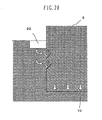
- the material of the claw-equipped core 10 is caused to flow radially inward toward the yoke 9 as indicated by arrows in Fig. 20, and the yoke 9 and the claw-equipped core 10 can be jointed to each other in a state where radial compressive stresses are held therein. Also, since the material of the claw-equipped core 10 subjected to the plastic flow is more apt to flow in the axial direction, component forces acting from the annular grooves 40 toward the bottom surface 25 of the joining hole 23 become larger, whereby stresses acting to closely contact the yoke 9 and the claw-equipped core 10 with each other in the axial direction can also be held therein.
- the yoke 9 and the claw-equipped core 10 can be maintained in a closely contacted state, and a gap between the claw-equipped core 10 and the stator core 3 can be set to a minimum value so that they are positioned as close as possible.
- magnetic characteristics are improved, an output is increased, and magnetic noise is reduced.
- the yoke 9 and the claw-equipped core 10 can be joined to each other in a state where larger axial compressive stresses act between the bottom surface of the joining hole 23 and the end of the yoke 9.
- the material of the claw-equipped core 10 is caused to fill into the annular grooves 40 when the claw-equipped core 10 is subjected to plastic flow.
- the material of the claw-equipped core 10 is not just pressed against the yoke 9, but it is caused to bite into the yoke 9, whereby the yoke 9 and the claw-equipped core 10 can be joined to each other with higher reliability.
- the annular grooves 40 are knurled by cold forging, a portion around the annular grooves 40 is hardened so that the material of the claw-equipped core 10 can more easily bite into the yoke 9.
- the material of the claw-equipped core 10 is able to more easily bite into the yoke 9.
- the number of the claws of the claw-equipped core 10 may be eight instead of six. Namely, the number and the shape of the claws is a matter of choice in design. When the number of the claws is increased, the number of magnetic flux paths is also increased and the efficiency of power generation is improved correspondingly. On the other hand, the strength of each claw is reduced. Therefore, the number of the claws is required to be set to an appropriate number.
- each yoke 9 and 12 are each formed into a cylindrical shape in the above-described embodiment, the yoke is not always required to have a cylindrical shape so long as it is tubular. Depending on applications, each yoke can be formed into a polygonal shape, a partly cutout shape, or any other suitable shape.
- the fitting portion is constituted by the joining hole 23 formed in the claw-equipped core 10 in the above-described embodiment
- plastic flow may be performed in such a state that a joining hole is formed in the yoke 9 and a projection formed on the claw-equipped core 10 is fitted to the joining hole of the yoke.
- the joining hole 23 is not always required to be a recess directly formed in the claw-equipped core 10 or the yoke 9.
- the joining hole 23 may be given as a recess formed by raising a portion around the joining hole 23.
- the pressing mark 22 is formed in the outer peripheral edge of the joining hole 23 in the above-described embodiment, the pressing mark 22 is not always required to be positioned just at the edge of the joining hole 23 and it may be formed at a certain distance away from the edge the joining hole 23. When a portion around the joining hole 23 is in the protruded form, the pressing mark 22 may be positioned in a side surface of the protruded portion around the joining hole 23.
- the pressing mark 22 is formed in an annular shape in the above-described embodiment, the pressing mark is not always required to have an annular shape and it may be formed at plural positions in the circumferential direction. When the pressing mark is formed at plural positions, those marks are preferably positioned at equal intervals in the circumferential direction.
- the groove is not always required to have an annular shape and it may be formed at plural positions in the circumferential direction.
- those grooves are preferably positioned at equal intervals in the circumferential direction.
- the groove can be formed in the claw-equipped core 10.
- annular groove 40 is subjected to cold rolling for work hardening in the above-described embodiment, any other suitable method can also be used so long as the method is able to harden the material forming the annular groove.
- cutting can be used instead.
- the yoke is required to be annealed in the case of causing the material of the yoke to flow by plastic flow.
- plastic flow is employed in the above-described embodiment as means for mechanically integrating the claw-equipped core 10 and the yoke 9, they may be mechanically integrated with each other by any other suitable means, such as friction welding.
- the joining hole 23 is formed as a hole in the form of a recess equipped with the bottom in the above-described embodiment, the joining hole may be formed, for example, as a hole penetrating through the claw-equipped core 10 at the same diameter as that of a base portion of the yoke 9.
Abstract
Description
- The present invention relates to a rotating electrical machine or an alternator and a method of manufacturing a rotor core used in the rotating electrical machine or the alternator.
- In a known alternator, plate-like rotor cores are disposed at opposite ends of a cylindrical yoke which is disposed in the inner peripheral side, and a plurality of claws are axially projected from outer peripheries of the rotor cores in alternately interdigitated relation. A shaft is inserted within the yoke. Further, because of the necessity of arranging a field coil between inner peripheries of the claws and an outer periphery of the yoke, the yoke is divided into a plurality of pieces and the divided yoke pieces are fixed to each other after arranging the field coil in place.
- Patent Document 1 (
JP-B-61-000979 - With the rotor core structure disclosed in
Patent Document 1, however, because the claw-equipped cores and the yoke are held in contact with each other just by respective fastening forces to the shaft, rigidity is low and claws are apt to open in the radial direction with elastic deformation by the action of a centrifugal force during high-speed rotation. For that reason, an air gap has to be set to a larger value so that the claws will not contact with a stator core disposed around the claw-equipped cores. This leads to another problem that magnetic resistance is increased in a magnetic path extending from the claw-equipped cores to the stator core and efficiency is deteriorated. - An object of the present invention is to provide a rotating electrical machine or an alternator in which claws of a rotor core are hard to open in the radial direction even under the action of a centrifugal force during rotation and an air gap between the claws and a stator core can be reduced, and a method of manufacturing a rotor core used in the rotating electrical machine or the alternator.
- To achieve the above object, the present invention is featured in that a yoke is joined to a claw-equipped core by plastic flow.
- Also, the present invention is featured in that the claw-equipped core and the yoke are mechanically integrally joined to each other.
- Further, the present invention is featured in comprising the steps of forming a fitting portion in the claw-equipped core, fitting the yoke to the fitting portion, and axially pressing a part of the claw-equipped core around the fitting portion to be plastically deformed, thereby joining the claw-equipped core and the yoke to each other.
- According to the present invention, claws of the rotor core are hard to open in the radial direction even under the action of a centrifugal force during rotation and an air gap between the claws and a stator core can be reduced. As a result, magnetic performance can be ensured at a sufficient level.
-
- Fig. 1 is a longitudinal sectional view showing one example of a vehicular alternator using a rotor core according to the present invention;
- Fig. 2 is a longitudinal sectional view showing one example of the rotor core according to the present invention;
- Fig. 3 is a perspective view of the rotor core according to the present invention;
- Fig. 4 is a perspective view of a yoke alone according to the present invention;
- Fig. 5 is a longitudinal sectional view of a claw-equipped core alone according to the present invention;
- Fig. 6 is a perspective view of the claw-equipped core alone according to the present invention;
- Fig. 7 is a longitudinal sectional view showing a state where the claw-equipped core and the yoke are set on a die in a plastic-flow joining process according to the present invention;
- Fig. 8 is a longitudinal sectional view showing a state just before the joining between the claw-equipped core and the yoke is started in the plastic-flow joining process according to the present invention;
- Fig. 9 is a longitudinal sectional view showing a state just after the joining between the claw-equipped core and the yoke is completed in the plastic-flow joining process according to the present invention;
- Fig. 10 is a partially enlarged longitudinal sectional view showing one example of portions of the claw-equipped core and the yoke joined to each other according to the present invention;
- Fig. 11 is a partially enlarged longitudinal sectional view showing another example of the portions of the claw-equipped core and the yoke joined to each other according to the present invention;
- Fig. 12 is a partially enlarged longitudinal sectional view showing still another example of the portions of the claw-equipped core and the yoke joined to each other according to the present invention;
- Fig. 13 is a perspective view showing one example of the yoke according to the present invention;
- Fig. 14 is a partially enlarged longitudinal sectional view showing one example of shape of an annular groove in the yoke according to the present invention;
- Fig. 15 is a partially enlarged longitudinal sectional view showing another example of shape of the annular groove in the yoke according to the present invention;
- Fig. 16 is a partially enlarged longitudinal sectional view showing still another example of shape of the annular groove in the yoke according to the present invention;
- Fig. 17 is a partially enlarged longitudinal sectional view showing dimensions of the portions of the claw-equipped core and the yoke joined to each other according to the present invention;
- Fig. 18 is a partial longitudinal sectional view showing elastic deformation caused by a centrifugal force in a state where a yoke and a core are fastened to a rotary shaft in the related art;
- Fig. 19 is a partial longitudinal sectional view showing elastic deformation caused by a centrifugal force in a state where the rotor core according to the present invention is fastened to a rotary shaft; and
- Fig. 20 is a partially enlarged longitudinal sectional view showing how stresses act in the present invention.
- One example of a vehicular alternator will be described below as a typical example of a rotating electrical machine according to one embodiment of the present invention. Fig. 1 is a longitudinal sectional view of the vehicular alternator.
- A
stator core 3 is held between afront housing 1 and arear housing 2. Thefront housing 1, therear housing 2, and thestator core 3 are fixed together by tightening screws and nuts (not shown) to apply a strong force in the direction in which thefront housing 1 and therear housing 2 grip thestator core 3 between them. Thefront housing 1 includes a flange 1a which is used to fix the alternator to a bracket provided on an engine block (not shown). Thestator core 3 has a plurality of teeth formed along an entire inner periphery facing the rotor side, andstator coils 4 are wound over the teeth. Three-phase AC voltages are induced in thestator coils 4 with the rotation ofmagnetized rotor cores 11 and 14 (described later). - A
rotary shaft 5 is rotatably supported by thefront housing 1 and therear housing 2 through abearing 6 provided in thefront housing 1 and abearing 7 provided in therear housing 2. Apulley 8 for receiving torque from a driving source, i.e., an engine, is fastened to an end of therotary shaft 5 on the same side as thefront housing 1 by screwing a nut. Arotor core 11 is made up of a hollowcylindrical yoke 9 and a claw-equippedcore 10 having a plurality (six in the illustrated example) ofclaws 15, which are integrally projected from an outer peripheral portion of thecore 10 so as to serve as magnetic poles, theyoke 12 and the claw-equippedcore 10 being integrated with each other by the method according to the present invention. Arotor core 14 is made up of ayoke 12 and a claw-equippedcore 13 which are integrated with each other similarly to therotor core 11. The claw-equippedcore 10 and the claw-equippedcore 13 are fixed to a substantially central area of therotary shaft 5 to be held in mutually fixed state. Theclaws cores rotor cores rotary shaft 5 by causing parts of theyokes rotary shaft 5 by plastic flow. Therotary shaft 5 is made of an iron-based material, i.e., S45C, and the claw-equippedcores yokes rotor cores - A
field coil 17 is wound over theyokes rotor cores slip ring 18 is fastened to an end of therotary shaft 5 on the side nearer to therear housing 2 and is supplied with a current from the exterior through abrush 19. When a current is supplied to thefield coil 17 from the exterior, magnetic flux is generated in therotor cores stator core 3 on the housing side, to thereby constitute a magnetic flux path as indicated by an arrow ω in Fig. 1. When torque is inputted to therotary shaft 5 through thepulley 8 and therotor cores rotary shaft 5 in the state of the magnetic flux path being thus formed, an AC electromotive force is induced in thestator coils 4. - The claw-equipped
core 10 and theyoke 9 will be described in more detail below. The claw-equippedcore 10 is desirably made of a material that is easily subjected to plastic working and has superior magnetic characteristics, i.e., low carbon steel in which the C content is 0.1% or less. Theyoke 9 is also desirably made of a material that is easily subjected to plastic working and has superior magnetic characteristics, i.e., low carbon steel in which the C content is 0.1% or less. - Figs. 5 and 6 show one example of the claw-equipped
core 10 according to the present invention. The claw-equippedcore 10 has abase portion 10a substantially in the form of a starfish, and sixclaws 15 are projected from thebase portion 10a in the axial direction of the rotary shaft 5 (i.e., the upward direction in Fig. 2) such that eachclaw 15 has a tapered shape. Theclaws 15 are not necessarily required to project exactly parallel to therotary shaft 5, and theclaws 15 may be inclined to some extent with respect to therotary shaft 5 so long as they are projected substantially in the axial direction of therotary shaft 5. A joininghole 23 in the form of a recessed hole is formed as a fitting portion substantially at a central position of one surface of the starfish-shapedbase portion 10a on the side where theclaws 15 are projected. The joininghole 23 has a diameter slightly larger than an outer diameter of theyoke 9. Further, acore center hole 20 through which is inserted therotary shaft 5 is formed substantially at a central position of the bottom of the joininghole 23 so as to penetrate the starfish-shapedbase portion 10a up to the opposite side. The corecentral hole 20 is also utilized as a positioning hole when theyoke 9 is plastically joined to the claw-equippedcore 10. - Fig. 4 shows one example of the
yoke 9 according to the present invention. Theyoke 9 has a hollow cylindrical shape with a through-hole 21 formed at a center to penetrate thoroughly. The through-hole 21 is formed to be positioned in substantially continuous relation to the corecentral hole 20. Similarly to the roles of the corecentral hole 20, the through-hole 21 also receives therotary shaft 5 and is utilized as a positioning hole when theyoke 9 is plastically joined to the claw-equippedcore 10. Further, as shown in enlarged views of Figs. 11 and 14, a plurality (two in the illustrated example) of grooves each having sloped surfaces in a cross-section as viewed in the axial direction, i.e.,annular grooves 40 each having an almost triangular axial cross-section, are preferably formed in an outer diameter portion of theyoke 9 near one end thereof, which portion is to be joined to the claw-equippedcore 10, thus providing substantially saw-toothedannular grooves 40. - Figs. 2 and 3 show one example of the
rotor core 11 made up of the claw-equippedcore 10 and theyoke 9 according to the present invention. By fitting the end of theyoke 9 on the side where theannular grooves 40 are formed to the joininghole 23 of the claw-equippedcore 10 and locally pressing an outer peripheral edge of the joininghole 23, theyoke 9 and the claw-equippedcore 10 are plastically joined to each other while apressing mark 22 is left as shown. - A plastically joining process will be described below with reference to Figs. 7, 8 and 9. As shown in Fig. 7, the core
central hole 20 formed in the claw-equippedcore 10 is inserted through a column-like mandrel 30 fixed on aplate 29 such that the claw-equippedcore 10 is held in an illustrated state. Thereafter, anend 42 of theyoke 9 on the side where theannular grooves 40 are formed is fitted to the joininghole 23 of the claw-equippedcore 10. Portions of the claw-equippedcore 10 and theyoke 9 fitted to each other are desirably dimensioned to allow clearance fit when the end of theyoke 9 is fitted to the joininghole 23 of the claw-equippedcore 10. The fitted portions of the claw-equippedcore 10 and theyoke 9 are as shown in an enlarged longitudinal sectional view of Fig. 10 or 11. - Subsequently, as shown in Fig. 8, a
punch 27 having amandrel insertion hole 27a formed to penetrate therethrough is fitted over themandrel 30, thus coming into a state just before the start of pressing. Then, by pressing thepunch 27 to drive it in the direction of an arrow by a press ram (not shown), anannular boss 28 of thepunch 27 presses a portion of anend surface 24 of the claw-equippedcore 10 which is positioned near the joininghole 23, desirably the outer peripheral edge of the joininghole 23. - Fig. 9 shows a state where the pressing is completed. A pressing force of the
punch 27 is set to apply a load for generating stresses sufficient to plastically deform the material of the claw-equippedcore 10 so that the material near the joininghole 23 is deformed in the axial direction of therotary shaft 5 to flow into theannular grooves 40 by plastic flow for joining theyoke 9 and the claw-equippedcore 10 together. At that time, since theannular grooves 40 have the triangular cross-sections, the sloped surfaces enable the material to flow more easily by plastic flow. Therefore, compressive stresses can also be more easily generated. The fitted portions after being subjected to the plastic flow in such a manner are as shown in the enlarged longitudinal sectional view of Fig. 11. Alternatively, as shown in Fig. 10, theannular grooves 40 are not necessarily required to be formed in theyoke 9 and a part of the claw-equippedcore 10 may be pressed and joined to an outer periphery of theyoke 9 just by plastic flow. - When the material near the joining
hole 23 is deformed to flow into theannular grooves 40 by plastic flow, resulting pressure is transmitted in the axial direction, whereby anend surface 43 of theyoke 9 is joined to thebottom surface 25 of the joininghole 23 of the claw-equippedcore 10 in close contact relation by that joining pressure. Therefore, the joining is completed in such a state that theend surface 43 of theyoke 9 and thebottom surface 25 of the joininghole 23 of the claw-equippedcore 10 are closely contacted with each other while adhesion stresses are held and enclosed between them. As a result, magnetic characteristics are improved, an output is increased, and magnetic noise is reduced. - Further, a boss width W of the
annular boss 28 of thepunch 27 and a pressing depth H, shown in Fig. 17, are desirably set in conformity with the shape of theannular grooves 40 for the reason as follows. If the boss width W and the pressing depth H are too large, the material is caused to flow in amount in excess of the amount allowable to flow into theannular grooves 40 and the claw-equippedcore 10 is deformed, thus resulting in deterioration of joining accuracy. The joining strength is increased with an increase in a depth K of theannular grooves 40. However, if the depth K of theannular grooves 40 is too large, the strength of the claw-equippedcore 10 itself is reduced because the depth of the joininghole 23 has to be increased and the thickness of the claw-equippedcore 10 at the bottom of the joininghole 23 is reduced correspondingly. Also, an increase in the depth K of theannular grooves 40 requires a larger amount of plastic flow and a larger pressing force, whereby the joining accuracy is deteriorated. In this embodiment, therefore, theannular grooves 40 are shaped to have the groove depth K of about 0.3 - 0.5 mm, a groove angle θ of about 60° - 90°, and a groove width K' of about 0.6 - 2 mm. Further, the boss width W is set to about 0.5 - 1.6 mm and the pressing depth H is set to about 0.4 - 1 mm. - The cross-sectional shape of the
annular grooves 40 of theyoke 9 is not necessarily required to be triangular as shown in Fig. 14. More specifically, theannular grooves 40 can be replaced with circularly curved grooves, i.e.,grooves 44 having substantially semicircular curved surfaces in an axial cross-section as shown in Fig. 15, or with asingle groove 45 having a trapezoidal shape as shown in Fig. 16. The substantiallysemicircular grooves 44 are easier to machine it and enable the plastic flow to be more easily caused along their inner curved surfaces. Thetrapezoidal groove 45 is even easier to machine it and is suitable for manufacturing a product at an inexpensive cost. Because the groove depth cannot be so increased when the annular groove is formed to have a substantially semicircular cross-section, the substantially semicircular groove is suitably used for a yoke having a relatively large diameter. The number of the annular grooves is not limited to a particular number and it may be one or plural. When a plurality of annular grooves are formed, the grooves may be spaced from each other by a certain distance or may be formed in a spiral shape. Further, by machining the annular grooves by cold rolling, the strength of groove portions is increased by work hardening and a degree of deformation caused during the joining process is reduced, thus resulting in higher joining strength. In particular, when the groove inner surface is formed to have a roughly projected and recessed shape by knurling as shown in Figs. 12 and 13, a larger degree of the rolling work is obtained so as to provide higher work hardening. Thus, the knurling of the groove inner surface is effective in increasing the groove strength and the joining strength. Moreover, by making the claw-equippedcore 10 softer than theyoke 9 with annealing, for example, since a hardness difference between the claw-equippedcore 10 and theyoke 9 is increased, it is possible to reduce the amount of deformation of theannular grooves 40 of theyoke 9 in the plastic-flow joining process, and to increase the joining strength. - After the completion of the plastic-flow joining process as shown in Fig. 9, the press ram (not shown) is ascended to move the
punch 27 away from theyoke 9, and therotor core 11 including theyoke 9 and the claw-equippedcore 10 integrally joined to each other is removed from theplate 29 and themandrel 30. Therotor core 11 is thereby completed. - Because the claw-equipped
core 10 and theyoke 9 are integrally joined to each other in coaxial relation with the aid of themandrel 30, they have superior coaxial accuracy. Therefore, when the thus-obtainedrotor core 11 is fastened to therotary shaft 5, balance required as a rotating member can be easily established. - When the
rotor core 11 is subjected to a centrifugal force with high-speed rotation of therotary shaft 5, the claw-equipped core and the yoke tend to separate at their contact surfaces by the action of a centrifugal force F, as shown in Fig. 18, if they are not joined to each other by plastic flow. On the other hand, in the case of therotor core 11 in which the claw-equippedcore 10 and theyoke 9 are joined to each other by plastic flow as in this embodiment, the contact surfaces of the claw-equippedcore 10 and theyoke 9 are hard to separate from each other even under the action of the centrifugal force F because, as shown in Fig. 19, radial compressive stresses Pr are generated along the entire circumference of the claw-equippedcore 10 by the axial joining force and adhesion forces between the claw-equippedcore 10 and theyoke 9 are held therein as residue stresses by the presence of axial stresses Ps. - Further, with the
annular grooves 40 formed in theyoke 9, the material caused to flow into theannular grooves 40 by plastic flow develops the so-called spike effect which makes the contact surfaces of the claw-equippedcore 10 and theyoke 9 harder to separate from each other. When theannular grooves 40 have the knurled inner surfaces, the resistance against forces in the rotating direction as well can be further increased. - Because the
rotor cores rotor core 14 is manufactured in the same manner as therotor core 11. Therotor cores rotary shaft 5 by a similar method to the above-described method used for joining theyokes cores yokes rotor cores - The claw-equipped
core 10 and theyoke 9 can be manufactured respectively at inexpensive costs, for example, by cold-forging of a blank which is obtained by punching a low-carbon steel plate into a starfish-like shape, and by cold-forging of a round rod under compression. As an alternative, the claw-equippedcore 10 and theyoke 9 may be manufactured by cutting. - The advantages of this embodiment will be described below.
- The
rotor cores yokes cores - Since the
rotor cores yokes cores yokes cores cores rotor cores - Since the
yoke 9 and the claw-equippedcore 10 are joined to each other by plastic deformation, the material of the claw-equippedcore 10 is caused to flow radially inward toward theyoke 9 as indicated by arrows in Fig. 20, and theyoke 9 and the claw-equippedcore 10 can be jointed to each other in a state where radial compressive stresses are held therein. Also, since the material of the claw-equippedcore 10 subjected to the plastic flow is more apt to flow in the axial direction, component forces acting from theannular grooves 40 toward thebottom surface 25 of the joininghole 23 become larger, whereby stresses acting to closely contact theyoke 9 and the claw-equippedcore 10 with each other in the axial direction can also be held therein. Even with the centrifugal force acting on the claw-equippedcore 10, therefore, theyoke 9 and the claw-equippedcore 10 can be maintained in a closely contacted state, and a gap between the claw-equippedcore 10 and thestator core 3 can be set to a minimum value so that they are positioned as close as possible. As a result, magnetic characteristics are improved, an output is increased, and magnetic noise is reduced. In particular, by forming the bottom-equipped joininghole 23 in the claw-equippedcore 10, fitting the end of theyoke 9 to the joininghole 23, and then causing a part of the claw-equippedcore 10 to deform by plastic flow, theyoke 9 and the claw-equippedcore 10 can be joined to each other in a state where larger axial compressive stresses act between the bottom surface of the joininghole 23 and the end of theyoke 9. - Further, since the
annular grooves 40 are formed in the outer periphery of theyoke 9 near its one end, the material of the claw-equippedcore 10 is caused to fill into theannular grooves 40 when the claw-equippedcore 10 is subjected to plastic flow. Thus, the material of the claw-equippedcore 10 is not just pressed against theyoke 9, but it is caused to bite into theyoke 9, whereby theyoke 9 and the claw-equippedcore 10 can be joined to each other with higher reliability. Moreover, since theannular grooves 40 are knurled by cold forging, a portion around theannular grooves 40 is hardened so that the material of the claw-equippedcore 10 can more easily bite into theyoke 9. In addition, by annealing the claw-equippedcore 10 to make it softer, the material of the claw-equippedcore 10 is able to more easily bite into theyoke 9. - While the present invention has been described above in connection with one embodiment, the number of the claws of the claw-equipped
core 10 may be eight instead of six. Namely, the number and the shape of the claws is a matter of choice in design. When the number of the claws is increased, the number of magnetic flux paths is also increased and the efficiency of power generation is improved correspondingly. On the other hand, the strength of each claw is reduced. Therefore, the number of the claws is required to be set to an appropriate number. - While the embodiment has been described above in connection with the rotor core of the alternator, similar advantages to those of the above-described embodiment can also be obtained so long as the rotor core is a rotatable member regardless of the type of rotating electrical machine.
- While the
yokes - While the fitting portion is constituted by the joining
hole 23 formed in the claw-equippedcore 10 in the above-described embodiment, plastic flow may be performed in such a state that a joining hole is formed in theyoke 9 and a projection formed on the claw-equippedcore 10 is fitted to the joining hole of the yoke. Also, the joininghole 23 is not always required to be a recess directly formed in the claw-equippedcore 10 or theyoke 9. For example, the joininghole 23 may be given as a recess formed by raising a portion around the joininghole 23. - While the
pressing mark 22 is formed in the outer peripheral edge of the joininghole 23 in the above-described embodiment, thepressing mark 22 is not always required to be positioned just at the edge of the joininghole 23 and it may be formed at a certain distance away from the edge the joininghole 23. When a portion around the joininghole 23 is in the protruded form, thepressing mark 22 may be positioned in a side surface of the protruded portion around the joininghole 23. - While the
pressing mark 22 is formed in an annular shape in the above-described embodiment, the pressing mark is not always required to have an annular shape and it may be formed at plural positions in the circumferential direction. When the pressing mark is formed at plural positions, those marks are preferably positioned at equal intervals in the circumferential direction. - While the embodiment has been described above as forming, in the
yoke 9, theannular groove 40 into which is caused the material to flow by plastic flow, the groove is not always required to have an annular shape and it may be formed at plural positions in the circumferential direction. When the groove is formed in plural positions, those grooves are preferably positioned at equal intervals in the circumferential direction. Further, when the material of theyoke 9 is caused to flow by plastic flow, the groove can be formed in the claw-equippedcore 10. - While the embodiment has been described above as knurling the inner surface of the
annular groove 40, similar advantages to those of the above-described embodiment can also be obtained if certain irregularities including projections and recesses are present within the groove. - While the
annular groove 40 is subjected to cold rolling for work hardening in the above-described embodiment, any other suitable method can also be used so long as the method is able to harden the material forming the annular groove. For example, cutting can be used instead. - While the claw-equipped
core 10 is subjected to annealing to make the claw-equippedcore 10 softer than theyoke 9 in the above-described embodiment, the yoke is required to be annealed in the case of causing the material of the yoke to flow by plastic flow. As an alternative method of providing a difference in hardness between the claw-equippedcore 10 and theyoke 9, it is also conceivable to change their materials. - While plastic flow is employed in the above-described embodiment as means for mechanically integrating the claw-equipped
core 10 and theyoke 9, they may be mechanically integrated with each other by any other suitable means, such as friction welding. - While the joining
hole 23 is formed as a hole in the form of a recess equipped with the bottom in the above-described embodiment, the joining hole may be formed, for example, as a hole penetrating through the claw-equippedcore 10 at the same diameter as that of a base portion of theyoke 9. - Other embodiments derived from the above-described embodiment and not set forth in claims will be described below along advantages thereof.
- (1) An alternator featured in including two rotor cores in each of which a claw-equipped core having claws projecting in the axial direction and a yoke disposed on the inner peripheral side of the claws in contact with an axially-faced side surface of the claw-equipped core are mechanically integrally joined to each other, wherein the two rotor cores are fixed to a rotary shaft such that end surfaces of the yokes are held in a mutually abutted state while allowing a field coil to be disposed between inner peripheries of the claws and outer peripheries of the yokes. Those features can provide similar advantages to those obtained with the alternator set forth in
Claim 12. - (2) A rotor core of an alternator, which is featured in that the claw-equipped core having the claws projecting in the axial direction and the yoke disposed on the inner peripheral side of the claws in contact with the axially-faced side surface of the claw-equipped core are joined to each other while residue stresses in both the radial direction and the axial direction are held therein. With that feature, contact surfaces of the claw-equipped core and the yoke are harder to separate from each other even when a large centrifugal force acts on them during high-speed rotation.
- (3) A rotor core of an alternator, which is featured in that the claw-equipped core having the claws projecting in the axial direction and the yoke disposed on the inner peripheral side of the claws in contact with the axially-faced side surface of the claw-equipped core are integrally joined to each other, and a hardened portion is formed near the interface between the claw-equipped core and the yoke to have larger hardness than other portion. With that feature, since the strength in the portion near the interface between the claw-equipped core and the yoke is increased, the claw-equipped core and the yoke can be prevented from separating from each other at a minimum possibility even when a large centrifugal force acts on them during high-speed rotation.
- (4) The rotating electrical machine described in (3), which is featured in that the hardened portion is formed in an annular shape. With that feature, since the strength in the portion near the interface between the claw-equipped core and the yoke is increased in an annular area, the claw-equipped core and the yoke can be prevented from separating from each other with higher reliability.
- (5) A method of manufacturing a rotor core of an alternator including two rotor cores each of which is made up of a claw-equipped core having claws projecting in the axial direction and a yoke disposed on the inner peripheral side of the claws in contact with an axially-faced side surface of the claw-equipped core, wherein each of the rotor cores is manufactured through the steps of forming a fitting portion in the claw-equipped core, fitting the yoke to the fitting portion, and axially pressing a part of the claw-equipped core around the fitting portion to be plastically deformed, thereby joining the claw-equipped core and the yoke to each other, and wherein the two rotor cores are fixed to a rotary shaft such that end surfaces of the yokes are held in a mutually abutted state while allowing a field coil to be disposed between inner peripheries of the claws and outer peripheries of the yokes. The manufacturing method having the above features can also provide similar advantages to those obtained with the manufacturing method set forth in
Claim 20. - Features, components and specific details of the structures of the above-described embodiments may be exchanged or combined to form further embodiments optimized for the respective application. As far as those modifications are readily apparent for an expert skilled in the art they shall be disclosed implicitly by the above description without specifying explicitly every possible combination, for the sake of conciseness of the present description.
Claims (20)
- A rotating electrical machine comprising:a rotor core (11, 14) made up of a claw-equipped core (10, 13) having claws (15, 16) projecting in the axial direction and a tubular yoke disposed on the inner peripheral side of said claws (15, 16) in contact with an axially-faced side surface of said claw-equipped core (10, 13);a field coil (17) disposed around said yoke (9, 12);
anda stator core (3) disposed with a gap left relative to said claw-equipped core (10, 13),wherein said yoke (9, 12) is jointed to said claw-equipped core (10, 13) by plastic flow. - The rotating electrical machine according to Claim 1, wherein a fitting portion is formed in said claw-equipped core (10, 13), and the plastic flow is performed in a state of said yoke (9, 12) being fitted to said fitting portion.
- The rotating electrical machine according to Claim 1 or 2, wherein a pressing mark generated with the plastic flow is formed in said claw-equipped core (10, 13) around said fitting portion.
- The rotating electrical machine according to at least one of Claims 1-3, wherein said pressing mark is formed in an annular shape.
- The rotating electrical machine according to at least one of Claims 1-4, wherein a groove (40) is formed in one of said claw-equipped core and said yoke (9, 12) at a position where the plastic flow is caused.
- The rotating electrical machine according to at least one of Claims 1-5, wherein said groove (40) is an annular groove.
- The rotating electrical machine according to at least one of Claims 1-6, wherein said annular groove (40) is knurled.
- The rotating electrical machine according to at least one of Claims 1-6, wherein said annular groove (40) is formed by cold rolling.
- The rotating electrical machine according to at least one of Claims 1-8, wherein said claw-equipped core (10, 13) is made of a material softer than a material of said yoke (9, 12).
- The rotating electrical machine according to at least one of Claims 1-9, wherein said claw-equipped core (10, 13) is subjected to annealing.
- The rotating electrical machine according to at least one of Claims 1-10, wherein said claw-equipped core (10, 13) and said yoke (9, 12) are coaxially joined to each other while said claw-equipped core (10, 13) and said yoke (9, 12) have the same diameter.
- An alternator comprising:a rotor core (11, 14) made up of a claw-equipped core (10, 13) having claws (15, 16) projecting in the axial direction and a tubular yoke disposed on the inner peripheral side of said claws (15, 16) in contact with an axially-faced side surface of said claw-equipped core (10, 13);a rotary shaft (5) for applying torque to said rotor core (11, 14);a field coil (17) disposed around said yoke (9, 12);a stator core (3) disposed with a gap left relative to said claw-equipped core (10, 13); anda stator coil (4) disposed on said stator core (3),wherein said rotor core (11, 14) is fixed to said rotary shaft (5) in a state where said yoke (9, 12) disposed on the inner peripheral side of said claws (15, 16) in contact with the axially-faced side surface of said claw-equipped core (10, 13) is integrally jointed to said claw-equipped core (10, 13).
- The alternator according to Claim 12, wherein said yoke (9, 12) is joined to said claw-equipped core (10, 13) while adhesion stresses are held in said yoke (9, 12).
- The alternator according to Claim 12 or 13, wherein, in said rotor core (11, 14), said yoke (9, 12) has a groove (40) formed in an outer periphery thereof and said yoke (9, 12) is fixed to said claw-equipped core (10, 13) with a part of said claw-equipped core (10, 13) biting into said groove (40).
- The alternator according to at least one of Claims 12-14, wherein, in said rotor core (11, 14), said groove (40) formed in the outer periphery of said yoke (9, 12) is formed as an annular groove (40).
- The alternator according to at least one of Claims 12-15, wherein, in said rotor core (11, 14), said annular groove (40) formed in the outer periphery of said yoke (9, 12) has a triangular cross-section.
- The alternator according to at least one of Claims 12-15, wherein, in said rotor core (11, 14), said annular groove (40) formed in the outer periphery of said yoke (9, 12) has a semi-circular cross-section.
- The alternator according to at least one of Claims 12-15, wherein, in said rotor core (11, 14), said annular groove (40) formed in the outer periphery of said yoke (9, 12) has a trapezoidal cross-section.
- The alternator according to at least one of Claims 12-15, wherein, in said rotor core (11, 14), said annular groove (40) formed in the outer periphery of said yoke (9, 12) is formed plural.
- A method of manufacturing a rotor core (11, 14) of a rotating electrical machine, said rotor core (11, 14) being made up of a claw-equipped core (10, 13) having claws (15, 16) projecting in the axial direction and a yoke (9, 12) disposed on the inner peripheral side of said yoke (9, 12) in contact with an axially-faced side surface of said claw-equipped core (10, 13), the method comprising the steps of:forming a fitting portion in said claw-equippedcore (10, 13);fitting said yoke (9, 12) to said fitting portion; andaxially pressing a part of said claw-equipped core (10, 13) around said fitting portion to be plastically deformed, thereby joining said claw-equipped core (10, 13) and said yoke (9, 12) to each other.
Applications Claiming Priority (1)
| Application Number | Priority Date | Filing Date | Title |
|---|---|---|---|
| JP2005355533A JP4856940B2 (en) | 2005-12-09 | 2005-12-09 | Rotating electric machine and manufacturing method thereof |
Publications (2)
| Publication Number | Publication Date |
|---|---|
| EP1796244A2 true EP1796244A2 (en) | 2007-06-13 |
| EP1796244A3 EP1796244A3 (en) | 2015-04-01 |
Family
ID=37857105
Family Applications (1)
| Application Number | Title | Priority Date | Filing Date |
|---|---|---|---|
| EP06025371.3A Withdrawn EP1796244A3 (en) | 2005-12-09 | 2006-12-07 | Rotating electrical machine for alternator and method of manufacturing rotor core used in the same |
Country Status (4)
| Country | Link |
|---|---|
| US (1) | US7737602B2 (en) |
| EP (1) | EP1796244A3 (en) |
| JP (1) | JP4856940B2 (en) |
| CN (1) | CN1980006B (en) |
Cited By (1)
| Publication number | Priority date | Publication date | Assignee | Title |
|---|---|---|---|---|
| FR3036550A1 (en) * | 2015-05-22 | 2016-11-25 | Valeo Systemes De Controle Moteur | METHOD FOR BLOCKING TWO PIECES |
Families Citing this family (13)
| Publication number | Priority date | Publication date | Assignee | Title |
|---|---|---|---|---|
| JP2008092673A (en) * | 2006-10-02 | 2008-04-17 | Denso Corp | Rotor of ac generator for vehicle |
| JP5268553B2 (en) * | 2008-10-15 | 2013-08-21 | 日立オートモティブシステムズ株式会社 | Rotating electric machine for vehicles |
| US20130187515A1 (en) * | 2010-03-31 | 2013-07-25 | Hitachi Ltd. | Vehicular Alternating Current Generator |
| JP5397396B2 (en) * | 2011-03-02 | 2014-01-22 | 株式会社デンソー | Manufacturing method of rotor core of rotating electrical machine |
| DE102012021048A1 (en) | 2011-10-31 | 2013-05-02 | Asmo Co., Ltd. | Rotor and motor |
| DE102012021049A1 (en) | 2011-10-31 | 2013-05-02 | Asmo Co., Ltd. | Rotor and motor |
| DE102012021041A1 (en) | 2011-10-31 | 2013-05-02 | Asmo Co., Ltd. | Rotor and motor |
| DE102012021109B4 (en) | 2011-10-31 | 2023-04-27 | Denso Corporation | rotor and engine |
| DE102012021042A1 (en) * | 2011-10-31 | 2013-05-02 | Asmo Co., Ltd. | Rotor and motor |
| FR3019399B1 (en) * | 2014-03-25 | 2016-03-11 | Valeo Equip Electr Moteur | FORGED POLAR WHEEL FOR A MOTOR VEHICLE ALTERNATOR WITH INTERPOLAR PERMANENT MAGNETS |
| CN103997142A (en) * | 2014-05-07 | 2014-08-20 | 江苏航天动力机电有限公司 | Electro-magnetic dual-salient-pole motor rotor |
| FR3040835B1 (en) * | 2015-09-03 | 2017-08-25 | Valeo Equip Electr Moteur | ROTATING ELECTRIC MACHINE COMPRISING A STEEL DIAMETER TREE AND METHOD OF ASSEMBLING SUCH A MACHINE |
| DE102018116988A1 (en) * | 2018-07-13 | 2020-01-16 | Nidec Corporation | Electric motor with one-piece inner rotor rotor core |
Citations (4)
| Publication number | Priority date | Publication date | Assignee | Title |
|---|---|---|---|---|
| JPS55117459A (en) * | 1979-03-05 | 1980-09-09 | Hitachi Ltd | Rotor of rotating-electric machine and its manufacturing method |
| GB2067850A (en) * | 1980-01-07 | 1981-07-30 | Hitachi Ltd | Rotor for a rotary electric machine and a method of manufacturing the same |
| JPH06178474A (en) * | 1992-12-04 | 1994-06-24 | Nippondenso Co Ltd | Field core with claw and its manufacture |
| JP2004320887A (en) * | 2003-04-16 | 2004-11-11 | Hitachi Ltd | Manufacturing method of rotor core |
Family Cites Families (22)
| Publication number | Priority date | Publication date | Assignee | Title |
|---|---|---|---|---|
| US2795715A (en) * | 1954-11-16 | 1957-06-11 | Leece Neville Co | Rotor construction for electrical machines |
| US3242364A (en) * | 1960-12-05 | 1966-03-22 | Bendix Corp | Electrical apparatus |
| US3529856A (en) * | 1969-01-08 | 1970-09-22 | Dumont Aviat Associates | Coupling and method of forming same |
| US3614593A (en) * | 1970-05-06 | 1971-10-19 | Motorola Inc | Rotary transformer for alternator |
| US4019799A (en) * | 1976-02-11 | 1977-04-26 | The Bendix Corporation | Electrical connector |
| DE2811323A1 (en) * | 1978-03-16 | 1979-09-27 | Bosch Gmbh Robert | RUNNER FOR ELECTRIC MACHINE |
| JPS567477A (en) * | 1979-06-29 | 1981-01-26 | Mitsubishi Electric Corp | Amplification switching semiconductor device |
| JPS57148552A (en) * | 1981-03-06 | 1982-09-13 | Hitachi Ltd | Coupling method for rotor of magneto generator |
| JPS58130756A (en) * | 1982-01-27 | 1983-08-04 | Hitachi Ltd | Rotor for ac generator |
| NL8400780A (en) * | 1984-03-12 | 1985-10-01 | Philips Nv | ROTOR FOR AN ELECTRICAL MACHINE. |
| JPS6168653A (en) * | 1984-09-12 | 1986-04-09 | Fujitsu Ltd | Area retrieval controlling system |
| US4703987A (en) * | 1985-09-27 | 1987-11-03 | Amphenol Corporation | Apparatus and method for retaining an insert in an electrical connector |
| US4746240A (en) * | 1987-04-01 | 1988-05-24 | General Motors Corporation | Self crimping connection for inner and outer members and method of assembling the same |
| DE3931442A1 (en) * | 1989-09-21 | 1991-04-04 | Bosch Gmbh Robert | Rotor for electrical generator or alternator in vehicle - uses cold forming to fit armature parts to rotor shaft |
| US5177391A (en) * | 1990-03-14 | 1993-01-05 | Nippondenso Co., Ltd. | Power generating apparatus |
| US5457588A (en) * | 1992-09-22 | 1995-10-10 | Nippon Densan Corporation | Low profile hydrodynamic motor having minimum leakage properties |
| DE19642784A1 (en) * | 1996-10-17 | 1998-04-23 | Bosch Gmbh Robert | Claw pole generator |
| JP2001054268A (en) * | 1999-08-06 | 2001-02-23 | Hitachi Ltd | Method for connecting shaft and hub of disk device and connection body thereof |
| JP3974315B2 (en) * | 2000-07-25 | 2007-09-12 | 三菱電機株式会社 | AC generator |
| JP2004072852A (en) * | 2002-08-05 | 2004-03-04 | Denso Corp | Rotor of rotary electric machine and manufacturing method thereof |
| JP3868361B2 (en) * | 2002-10-04 | 2007-01-17 | 株式会社日立製作所 | Plastic flow joint and its joining method |
| WO2005051717A2 (en) * | 2003-11-24 | 2005-06-09 | Jacobs Vehicle Systems, Inc. | Electromagnetic retarder system and method |
-
2005
- 2005-12-09 JP JP2005355533A patent/JP4856940B2/en not_active Expired - Fee Related
-
2006
- 2006-12-06 CN CN2006101641639A patent/CN1980006B/en not_active Expired - Fee Related
- 2006-12-07 EP EP06025371.3A patent/EP1796244A3/en not_active Withdrawn
- 2006-12-07 US US11/634,977 patent/US7737602B2/en not_active Expired - Fee Related
Patent Citations (4)
| Publication number | Priority date | Publication date | Assignee | Title |
|---|---|---|---|---|
| JPS55117459A (en) * | 1979-03-05 | 1980-09-09 | Hitachi Ltd | Rotor of rotating-electric machine and its manufacturing method |
| GB2067850A (en) * | 1980-01-07 | 1981-07-30 | Hitachi Ltd | Rotor for a rotary electric machine and a method of manufacturing the same |
| JPH06178474A (en) * | 1992-12-04 | 1994-06-24 | Nippondenso Co Ltd | Field core with claw and its manufacture |
| JP2004320887A (en) * | 2003-04-16 | 2004-11-11 | Hitachi Ltd | Manufacturing method of rotor core |
Cited By (2)
| Publication number | Priority date | Publication date | Assignee | Title |
|---|---|---|---|---|
| FR3036550A1 (en) * | 2015-05-22 | 2016-11-25 | Valeo Systemes De Controle Moteur | METHOD FOR BLOCKING TWO PIECES |
| WO2016189226A1 (en) * | 2015-05-22 | 2016-12-01 | Valeo Systemes De Controle Moteur | Method for immobilizing two components |
Also Published As
| Publication number | Publication date |
|---|---|
| CN1980006B (en) | 2010-05-19 |
| US20070132337A1 (en) | 2007-06-14 |
| EP1796244A3 (en) | 2015-04-01 |
| JP2007159378A (en) | 2007-06-21 |
| CN1980006A (en) | 2007-06-13 |
| JP4856940B2 (en) | 2012-01-18 |
| US7737602B2 (en) | 2010-06-15 |
Similar Documents
| Publication | Publication Date | Title |
|---|---|---|
| US7737602B2 (en) | Rotating electrical machine or alternator and method of manufacturing rotor core used in the same | |
| US4339873A (en) | Method of making rotor of rotary machines | |
| CN106961171B (en) | Rotor, motor, method for manufacturing rotor, and method for manufacturing motor | |
| CA2064627C (en) | Pulley with integral fastener and spacer | |
| EP2582015A1 (en) | Rotating electrical machine rotor | |
| US4792713A (en) | Lamination to rotor shaft retention method utilizing spring pins | |
| WO2006132171A1 (en) | Armature of rotating electric machine and method of manufacturing the same | |
| US10944306B2 (en) | Rotary electric rotor and method of manufacturing rotary electric rotor | |
| KR20070116054A (en) | Electrical rotating machine comprising an intermediate sleeve interposed between the shaft and the polar wheels and method for making the rotor | |
| JPS631012B2 (en) | ||
| JP4508925B2 (en) | Yoke for rotating electrical machine and method for manufacturing yoke | |
| JP2005520999A (en) | Assembly including pulley for automobile alternator and method for assembling the same | |
| JP2011254663A (en) | Manufacturing method of rotor for rotary electric machine and shaft material for rotary electric machine | |
| GB2029743A (en) | Flywheel magneto rotor and method of manufacture thereof | |
| US11336158B2 (en) | Manufacturing method of core of rotating electrical machine, and core of rotating electrical machine | |
| US20040251769A1 (en) | Electric machine, especially a starter device | |
| US4934042A (en) | Lamination to rotor shaft retention method utilizing spring pins | |
| WO2020255730A1 (en) | Start-up generator and method for manufacturing start-up generator | |
| JP2000329214A (en) | Assembly camshaft and manufacture thereof | |
| JP3727476B2 (en) | Rotating electric machine stator | |
| JP6139748B1 (en) | Rotating electric machine stator | |
| JPH1066287A (en) | Rotor of magnet generator | |
| JP2008067555A (en) | Rotor assembly and manufacturing method therefor | |
| JP4006638B2 (en) | Two-member plastic joining method and plastic joining jig | |
| JP2016220332A (en) | Rotary electric machine |
Legal Events
| Date | Code | Title | Description |
|---|---|---|---|
| PUAI | Public reference made under article 153(3) epc to a published international application that has entered the european phase |
Free format text: ORIGINAL CODE: 0009012 |
|
| AK | Designated contracting states |
Kind code of ref document: A2 Designated state(s): AT BE BG CH CY CZ DE DK EE ES FI FR GB GR HU IE IS IT LI LT LU LV MC NL PL PT RO SE SI SK TR |
|
| AX | Request for extension of the european patent |
Extension state: AL BA HR MK YU |
|
| 17P | Request for examination filed |
Effective date: 20090618 |
|
| PUAL | Search report despatched |
Free format text: ORIGINAL CODE: 0009013 |
|
| AK | Designated contracting states |
Kind code of ref document: A3 Designated state(s): AT BE BG CH CY CZ DE DK EE ES FI FR GB GR HU IE IS IT LI LT LU LV MC NL PL PT RO SE SI SK TR |
|
| AX | Request for extension of the european patent |
Extension state: AL BA HR MK RS |
|
| RIC1 | Information provided on ipc code assigned before grant |
Ipc: H02K 1/24 20060101AFI20150225BHEP Ipc: H02K 5/08 20060101ALI20150225BHEP Ipc: H02K 15/02 20060101ALI20150225BHEP Ipc: B21K 1/28 20060101ALI20150225BHEP |
|
| STAA | Information on the status of an ep patent application or granted ep patent |
Free format text: STATUS: THE APPLICATION HAS BEEN WITHDRAWN |
|
| 18W | Application withdrawn |
Effective date: 20150317 |