JP4856940B2 - Rotating electric machine and manufacturing method thereof - Google Patents
Rotating electric machine and manufacturing method thereof Download PDFInfo
- Publication number
- JP4856940B2 JP4856940B2 JP2005355533A JP2005355533A JP4856940B2 JP 4856940 B2 JP4856940 B2 JP 4856940B2 JP 2005355533 A JP2005355533 A JP 2005355533A JP 2005355533 A JP2005355533 A JP 2005355533A JP 4856940 B2 JP4856940 B2 JP 4856940B2
- Authority
- JP
- Japan
- Prior art keywords
- core
- yoke
- claw
- electrical machine
- rotating electrical
- Prior art date
- Legal status (The legal status is an assumption and is not a legal conclusion. Google has not performed a legal analysis and makes no representation as to the accuracy of the status listed.)
- Expired - Fee Related
Links
Images


Classifications
-
- H—ELECTRICITY
- H02—GENERATION; CONVERSION OR DISTRIBUTION OF ELECTRIC POWER
- H02K—DYNAMO-ELECTRIC MACHINES
- H02K15/00—Methods or apparatus specially adapted for manufacturing, assembling, maintaining or repairing of dynamo-electric machines
- H02K15/02—Methods or apparatus specially adapted for manufacturing, assembling, maintaining or repairing of dynamo-electric machines of stator or rotor bodies
- H02K15/022—Methods or apparatus specially adapted for manufacturing, assembling, maintaining or repairing of dynamo-electric machines of stator or rotor bodies with salient poles or claw-shaped poles
-
- B—PERFORMING OPERATIONS; TRANSPORTING
- B21—MECHANICAL METAL-WORKING WITHOUT ESSENTIALLY REMOVING MATERIAL; PUNCHING METAL
- B21K—MAKING FORGED OR PRESSED METAL PRODUCTS, e.g. HORSE-SHOES, RIVETS, BOLTS OR WHEELS
- B21K1/00—Making machine elements
- B21K1/28—Making machine elements wheels; discs
-
- B—PERFORMING OPERATIONS; TRANSPORTING
- B21—MECHANICAL METAL-WORKING WITHOUT ESSENTIALLY REMOVING MATERIAL; PUNCHING METAL
- B21K—MAKING FORGED OR PRESSED METAL PRODUCTS, e.g. HORSE-SHOES, RIVETS, BOLTS OR WHEELS
- B21K25/00—Uniting components to form integral members, e.g. turbine wheels and shafts, caulks with inserts, with or without shaping of the components
-
- H—ELECTRICITY
- H02—GENERATION; CONVERSION OR DISTRIBUTION OF ELECTRIC POWER
- H02K—DYNAMO-ELECTRIC MACHINES
- H02K1/00—Details of the magnetic circuit
- H02K1/06—Details of the magnetic circuit characterised by the shape, form or construction
- H02K1/22—Rotating parts of the magnetic circuit
- H02K1/24—Rotor cores with salient poles ; Variable reluctance rotors
- H02K1/243—Rotor cores with salient poles ; Variable reluctance rotors of the claw-pole type
-
- H—ELECTRICITY
- H02—GENERATION; CONVERSION OR DISTRIBUTION OF ELECTRIC POWER
- H02K—DYNAMO-ELECTRIC MACHINES
- H02K5/00—Casings; Enclosures; Supports
- H02K5/04—Casings or enclosures characterised by the shape, form or construction thereof
- H02K5/08—Insulating casings
-
- Y—GENERAL TAGGING OF NEW TECHNOLOGICAL DEVELOPMENTS; GENERAL TAGGING OF CROSS-SECTIONAL TECHNOLOGIES SPANNING OVER SEVERAL SECTIONS OF THE IPC; TECHNICAL SUBJECTS COVERED BY FORMER USPC CROSS-REFERENCE ART COLLECTIONS [XRACs] AND DIGESTS
- Y10—TECHNICAL SUBJECTS COVERED BY FORMER USPC
- Y10T—TECHNICAL SUBJECTS COVERED BY FORMER US CLASSIFICATION
- Y10T29/00—Metal working
- Y10T29/49—Method of mechanical manufacture
- Y10T29/49002—Electrical device making
- Y10T29/49009—Dynamoelectric machine
- Y10T29/49012—Rotor
Landscapes
- Engineering & Computer Science (AREA)
- Power Engineering (AREA)
- Mechanical Engineering (AREA)
- Manufacturing & Machinery (AREA)
- Iron Core Of Rotating Electric Machines (AREA)
- Synchronous Machinery (AREA)
- Manufacture Of Motors, Generators (AREA)
Description
本発明は回転電機およびその製造方法に関するものである。 The present invention relates to a rotating electrical machine and a method for manufacturing the same.
従来の交流発電装置は、内周側に設けられる円筒状のヨークの両端にプレート状のロータコアが設けられ、夫々のロータコアの外周から軸方向に互い違いに複数の爪が延在しており、ヨークの内部にはシャフトが挿入されるようになっている。また、爪の内周とヨークの外周との間に界磁コイルを配置する必要があることからヨークを分割し、界磁コイルを配置した後に互いのヨークが固定されるようになっている。 In a conventional AC power generator, plate-shaped rotor cores are provided at both ends of a cylindrical yoke provided on the inner peripheral side, and a plurality of claws are alternately extended in the axial direction from the outer periphery of each rotor core. A shaft is inserted into the inside of the. Further, since it is necessary to dispose the field coil between the inner periphery of the claw and the outer periphery of the yoke, the yokes are fixed after the yoke is divided and the field coils are disposed.
特許文献1には、大型化して製造設備が大きくならないよう、爪付コアとヨークを別体で構成し、夫々の部品をシャフトに締結することにより一体化させるものが開示されている。
しかしながら、特許文献1記載のロータコア構造によれば、爪付コアとヨークがシャフト締結力によってのみ接触しているため、剛性が低く、高回転時の遠心力によって爪が半径方向に弾性変形で開き易く、爪が外周に設けられたステータコアに接触しない様にエアギャップを大きくしなければならない欠点があった。このため、爪付コアからステータコアへの磁気抵抗が増大して効率が悪化しまうといった問題があった。
However, according to the rotor core structure described in
本発明の目的は、回転により遠心力が作用してもロータコアの爪が半径方向に開き難く、ステータコアとの間のエアギャップを小さくすることができる回転電機または交流発電装置およびその製造方法を提供することにある。 SUMMARY OF THE INVENTION An object of the present invention is to provide a rotating electrical machine or an AC power generation apparatus that can reduce the air gap between the rotor core and the stator core, and the manufacturing method thereof. There is to do.
上記目的は、軸方向に延在する爪を有する爪付コアと、前記爪の内周側にあって、前記爪付コアの軸方向側面の凹状の穴に固定される筒状のヨークと、前記爪付コアと前記ヨークとが結合される回転軸と、前記ヨーク外周に設けられたコイルと、前記爪付コアと隙間を介して配置されたステータコアと、を有する回転電機において、前記ヨークと前記穴の側壁との間の、少なくとも一方には環状溝が設けられ、前記環状溝を含んで、前記ヨークを塑性流動によって前記爪付コアに結合したことにより達成される。The object is to provide a core with a claw having a claw extending in the axial direction, a cylindrical yoke on the inner peripheral side of the claw and fixed to a concave hole on the side surface in the axial direction of the core with the claw, In the rotating electrical machine, comprising: a rotating shaft to which the clawd core and the yoke are coupled; a coil provided on the outer periphery of the yoke; and a stator core disposed with a gap between the clawed core and the yoke; An annular groove is provided in at least one of the side walls of the hole, and is achieved by including the annular groove and coupling the yoke to the clawed core by plastic flow.
また、上記目的は、軸方向に延在する爪を有する爪付コアと、前記爪の内周側にあって、前記爪付コアの軸方向側面の凹状の穴に固定される筒状のヨークと、前記爪付コアと前記ヨークとが固定される回転軸と、前記ヨーク外周に設けられたコイルと、前記爪付コアと隙間を介して配置されたステータコアと、を有する回転電機の製造方法において、前記ヨークと前記穴の側壁との少なくとも一方に環状溝を設け、前記穴に前記ヨークが嵌合し、前記環状溝を含んで、前記ヨークを塑性流動によって前記爪付コアに結合したことにより達成される。The object is also provided with a claw core having a claw extending in the axial direction, and a cylindrical yoke on the inner peripheral side of the claw and fixed to a concave hole on the side surface in the axial direction of the claw core. And a rotating shaft on which the claw core and the yoke are fixed, a coil provided on the outer periphery of the yoke, and a stator core disposed via the claw core and a gap. The annular groove is provided in at least one of the yoke and the side wall of the hole, the yoke is fitted into the hole, the annular groove is included, and the yoke is coupled to the clawed core by plastic flow. Is achieved.
本発明によれば、回転により遠心力が作用してもロータコアの爪が半径方向に開き難く、ステータコアとの間のエアギャップを小さくすることができる。このため、磁気性能を十分確保することできる。 According to the present invention, the claw of the rotor core is difficult to open in the radial direction even when centrifugal force is applied by rotation, and the air gap with the stator core can be reduced. For this reason, sufficient magnetic performance can be ensured.
本発明の一実施の形態である回転電機の代表例として、自動車用交流発電装置の例を説明する。図1は自動車用交流発電装置の断面図である。 As a representative example of a rotating electrical machine according to an embodiment of the present invention, an example of an automotive AC generator will be described. FIG. 1 is a cross-sectional view of an automotive AC generator.
フロントハウジング1とリアハウジング2との間にステータコア3が挟まれており、図示しない螺子とナットでフロントハウジング1とリアハウジング2とがステータコア3を挟みこむ方向に強い力を加えることで、フロントハウジング1とリアハウジング2とステータコア3とが一体に固定される。フロントハウジング1はフランジ部1aを備えており、このフランジ部で図示しないエンジンブロックに設けられたブラケットに前記交流発電装置が固定される。前記のロータ側である内側に全周に亘って複数の歯(ティース)を備えており、前記歯(ティース)にはステータコイル4が巻装されている。磁化された後述するロータコア11,14が回転することで、前記ステータコイル4には三相交流電圧が誘起される。
The
回転軸5はフロントハウジング1に設けられた軸受6とリアハウジング2に設けられた軸受7により前記フロントハウジング1およびリアハウジング2に回転自在に支承されている。回転軸5のフロントハウジング1側端部にはエンジンの駆動源から回転力が入力されるプーリ8がナットによりねじ締結されており、略中央には本発明に係る方法で一体化された中空円筒状のヨーク9と、外周部に磁極となる複数(実施例においては6本)の爪15が一体に設けられた爪付コア10からなるロータコア11と、該ロータコア11と同様に一体化されたヨーク12および爪付コア13からなるロータコア14が回転軸5に固定されることによって互いに固着され、夫々の爪付コア10,13における爪15,16が相互に入り込んで配置されている。尚、ロータコア11,14は、回転軸5に形成した環状溝内にヨーク9,12の一部が塑性流動することによって固定されている。回転軸5は鉄系材料であるS45C,ロータコア11,14の爪付コア10,13およびヨーク9,12は磁性材料である低炭素鋼で構成されている。
The
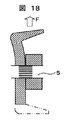
ロータコア11,14のヨーク9,12には界磁コイル17が巻装されており、回転軸5におけるリアハウジング2側にはスリップリング18が締結され,ブラシ19を介して外部より給電されるようになっている。このように外部から界磁コイル17に電流が供給されると各ロータコア11,14及びハウジング側のステータコア3周りに磁束が生じて図中ωの矢印にて示すように磁束通路が構成される。このため、磁束通路が構成された状態で回転軸5にプーリ8から回転力が入力されてロータコア11,14が回転軸5と共に回転するとステータコイル4に交流起電力が誘起される。
A
次に爪付コア10とヨーク9について説明する。爪付コア10の材質は塑性加工し易く、磁気特性に優れた低炭素鋼でC量0.1%以下の材質が望ましい。ヨーク9の材料においても、塑性加工し易く、磁気特性に優れた低炭素鋼で、C量0.1%以下が望ましい。
Next, the
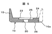
図5,図6は本発明による爪付コア10の一実施例を示したものである。爪付コア10は、海星状の基部10aから回転軸方向(図2中の上方向)に延在する6本の爪15を有し、各爪15は先細り形状となっている。尚、爪15は回転軸に対して完全に平行とする必要はなく、あくまで回転軸方向に延びていれば多少回転軸に対して傾斜して設けられていてもよい。また、海星状の基部10aにおける爪15が延在する側の側面の略中心位置には嵌合部としての凹状の穴である結合穴23が形成されており、該結合穴23はヨーク9の外径より若干大きな径に形成されている。更に、結合穴の底部の略中心位置には回転軸5が挿通されるコア中心穴20が海星状の基部10aの他側に貫通形成されており、このコア中心穴20はヨーク9を塑性結合させる際の位置決め穴としても利用される。
5 and 6 show an embodiment of the
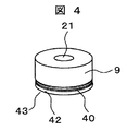
図4は本発明によるヨーク9の一実施例を示したものである。ヨーク9は中心に貫通した貫通穴21を有した中空円筒形状に形成され、貫通穴21はコア中心穴20とほぼ同じ位置にて連続するように設けられ、コア中心穴20の役割と同様に回転軸5が挿通されると共に、塑性結合させる際の位置決め穴としても利用される。また、図11,図14の拡大図に示す如くヨーク9の一端近傍の被結合外径部に軸方向断面が傾斜面を有する溝、つまり、略三角形状の環状溝40が複数(本実施例においては二重)形成されて略鋸形状の環状溝40として構成される。
FIG. 4 shows an embodiment of the
図2,図3は本発明による爪付コア10とヨーク9のロータコア11の一実施例を示したものである。ヨーク9における環状溝40が形成された側を爪付コア10の結合穴23に挿入し、該結合穴23の周縁を局部的に押圧することにより、押圧痕22を残して塑性結合されている。
2 and 3 show an embodiment of the
次に塑性結合工程について図7,図8,図9を基に説明する。図7に示すように爪付コア10に設けられたコア中心穴20をプレート29に固定された円柱形状のマンドレル
30に挿入して保持し、その後、爪付コア10の結合穴23にヨーク9の環状溝40が形成されている側の端部42を挿入嵌合する。尚、爪付コア10の結合穴23にヨーク9の端部42を挿入したときの爪付コア10とヨーク9の嵌合部は隙間ばめが望ましい。該嵌合部は図10もしくは図11の拡大縦断面図に示す如くなる。
Next, the plastic bonding process will be described with reference to FIGS. As shown in FIG. 7, the
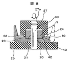
その後、内周にマンドレル挿入穴27aが貫通形成されたパンチ27を図8に示すようにマンドレル30に嵌合して押圧直前の状態になる。その後、図示しないプレスラムで矢印の方向から加圧し打ち込むとパンチ27の環状突起28が爪付コア10の端面24の結合穴23の近傍、望ましくは結合穴23の周縁を押圧する。
Thereafter, the
図9は押圧完了時の状態を示す。このパンチ27の押圧力は、爪付コア10を形成している材料が塑性変形するに足りる応力を生じさせる荷重で出来るだけ鉛直に、つまり、回転軸方向に結合穴23の近傍の材料を環状溝40に塑性流動させ結合する。このとき、環状溝40の断面が三角形状となっていることから傾斜面により塑性流動による素材の流れが生じやすくなる。このため、圧縮応力を生じさせ易くすることができる。この様に塑性結合された後の結合部は図11の拡大縦断面図に示す如くなっている。尚、図10に示すように、ヨーク9に環状溝を設けなくとも、塑性流動した爪付コア10の一部をヨーク9の外周側に押付けて結合させることができる。
FIG. 9 shows a state when the pressing is completed. The pressing force of the
結合穴23の近傍の材料が塑性流動し環状溝40に流動する際にヨーク9にはその圧力が軸方向に伝達されヨーク9の端面43が爪付コア10の結合穴23の底面25にこの結合圧力を持って密着しながら結合していき、ヨーク9の端面43と爪付コア10の結合穴23の底面25は密着応力を保持したまま結合が完了し封じ込められるために、磁気特性が向上する。出力が向上し、磁気騒音が低減する。
When the material in the vicinity of the
また、図17に示すようパンチ27の環状突起28による突起幅Wと押圧深さHは大きすぎると環状溝40内に流動する以上の材料を流動させることになり爪付コア10が変形するなど結合精度を悪化させてしまうため環状溝40の形状に合わせて設定することが望まれる。環状溝40の深さKを大きくすると結合強度が向上するがあまり大きくすると、結合穴23の穴深さを深くしなければならず、爪付コア10における結合穴23の底厚が薄くなり、爪付コア10自体の強度を低下させることになる。また塑性流動量が大きくなって押圧力も大きくなるので、結合精度が低下することになる。そのため本実施例における環状溝40形状は溝深さKを0.3〜0.5mm、溝角度θを60°〜90°、溝幅K′を0.6〜2mm程度として、突起幅Wを0.5〜1.6mm、押圧深さHを0.4〜1mm程度に設定している。
In addition, as shown in FIG. 17, if the protrusion width W and the pressing depth H by the
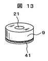
なお、ヨーク9の環状溝40の断面形状は図14に示す如き三角形状である必要はなく、図15に示すようなR形状、つまり軸方向断面が曲面を有する略半円形状の溝44や、図16に示すような台形形状の一重の溝45でもよい。略半円形状の溝44とした場合には、加工がし易く、かつ、溝内の曲面によって塑性流動を生じさせやすくすることができ、台形形状とした場合には、更に加工が優位となるため、安価な製品に適している。尚、環状溝の断面を半円形状とすると溝深さが深くできないので比較的径の大きなヨークに適用する方がよい。これらの環状溝の数は特定する必要はなく一重であっても複数設けられていても構わない。更に複数の環状溝を設ける場合には溝間が所定幅離れていても構わず、螺旋形状であっても構わない。また、これらの環状溝は冷間転造で加工すれば加工硬化して溝部の強度が向上し結合時の変形が少なく結合強度を向上させることが出来る。特に図12,図13に示すような溝の内面が荒く形成された凹凸形状であるローレット形状にすると転造加工度が大きく加工硬化して溝強度が向上し結合強度向上に効果的である。また爪付コア10を例えば、焼鈍したりすることにより、ヨーク9に対して軟らかくすると、ヨーク9との硬度差をさらに設けることができるため塑性流動結合した際にヨーク9の環状溝40の変形量が少なくさらに結合強度を向上することが出来る。
Note that the cross-sectional shape of the
図9の塑性流動結合完了後は図示しないプレスラムを上昇させ、パンチ27を離脱させ、一体に結合されたロータコア11をプレート29およびマンドレル30から取り出せば完成する。
9 is completed, the press ram (not shown) is raised, the
マンドレル30で同芯をもって結合されるため爪付コア10とヨーク9は同軸精度良く結合されており、このロータコア11を回転軸5に締結した際には回転体としてバランスを容易にえることができる。
Since the
また、ロータコア11は回転軸5が高回転で回転した際の遠心力に対しても、塑性流動結合しない場合には図18に示すように遠心力Fにより爪付コアとヨークの接触面が離れ易いが本実施例のように塑性流動結合した場合のロータコア11は軸方向結合力により半径方向の圧縮応力Prが全周に生じていること、および軸方向の応力Psにより爪付コア10とヨーク9の密着力がそれぞれ残留応力として保持されているため遠心力Fが働いても接触面は離れにくい。
Further, when the
またヨーク9の環状溝40があれば環状溝40に塑性流動した材料がスパイク効果をもってさらに接触面を離れ難くすることが出来る。環状溝40がローレット形状であればこれより更に回転方向の力にも強固に対抗することが出来る。
Further, if the
なおロータコア11と14は基本的に一対の同じ構造なのでロータコア11と同様であり、両方のロータコア11,14のヨーク9,12同士が接触した状態で回転軸5に形成されたローレット形状の環状溝にヨーク9,12と爪付コア10,13の結合方法と同様の方法にて塑性流動により軸方向及び回転方向に固定されている。
Since the
爪付コア10はたとえば低炭素鋼鈑を海星状に打抜きしたブランクにより冷間鍛造等で、ヨーク9は丸棒から圧縮により冷間鍛造により製作すれば安価に製造することが可能であるが切削加工によって製作することも可能である。
For example, the core with
次に本実施例の作用効果を以下に示す。 Next, the function and effect of this embodiment will be described below.
ロータコア11,14は、ヨーク9,12と爪付コア10,13を別々の部材で製造して、その後、塑性流動によって互いの部材を結合しているので、ヨークと爪付コアを1つの部品として一体に成形してしまうものに対して、冷間鍛造プレス工程,中間の焼鈍工程,潤滑処理工程等の製造設備が多大なものとならず、比較的小規模な設備で安価に生産できるといった作用効果が得られる。尚、冷間鍛造ではなく熱間鍛造を用いることも考えられるが、熱間鍛造では精度が低く、切削加工や冷間鍛造により形状精度を確保しなければならないので工程が複雑化しまうことに加え、省エネルギーの面からも問題があるため、熱間鍛造よりも冷間鍛造する方が望ましい。
In the
ロータコア11,14は、塑性流動によってヨーク9,12と爪付コア10,13を結合しているので、ロータコア11,14がエンジンの回転に伴い高速で回転したとしても爪付コア10,13に働く遠心力の影響でヨーク9,12と爪付コア10,13の当接箇所が離れてしまうことがない。このため、磁気抵抗が増大して磁気性能が悪化してしまうことがない。
Since the
また、ヨーク9と爪付コア10の間には塑性変形させることによって、図20の矢印で示すように爪付コア10の材料がヨーク9側に半径方向内側に流動し、半径方向の圧縮応力を保持させて結合することができる。また、流動した爪付コア10の材料は、軸方向に流れやすいことから、環状溝40における結合穴23の底面25側に作用する分力の方が大きくなり、このため軸方向の密着応力も保持させることができる。このため、爪付コア10に遠心力が作用したとしても爪付コア10とヨーク9が当接した状態を維持でき、爪付ヨーク10とステータコア3間の隙間を出来るだけ、近付けることができる。よって、磁気特性が向上することにより出力を向上でき、磁気騒音についても低減できるといった作用効果が得られる。特に爪付コア10に有底の結合穴23を形成し、この結合穴23にヨーク9の端部を嵌合した後に塑性流動させれば、結合穴23の底部とヨーク9の端部との間に軸方向の圧縮応力をより大きくした状態で結合させることができる。
Further, by plastically deforming between the
また、ヨーク9の一端には環状溝40を形成しているので爪付コア10を塑性流動させた際に爪付コア10の材料が環状溝40内に充填される。このため、爪付コア10の材料による単なるヨーク9への押圧ではなく食い込ませることができるのでより確実に結合することができる。尚、環状溝40は、冷間転造によりローレット形状としているので環状溝40の周りが硬くなり、爪付コア10の材料が食い込み易くなっている。更にヨーク9を焼鈍により柔らかくしているので、より材料を食い込み易くすることができる。
Since the
以上、本実施例について説明したが、爪付コア10の爪の数を6本とせず8本としても構わないし、爪の数や形状は問わない。尚、爪の数を多くすると磁束通路の数が多くなる分、発電効率は向上するが爪の強度が低下するため、適度な数に設定する必要がある。 Although the present embodiment has been described above, the number of claws of the core 10 with claws may be eight instead of six, and the number and shape of the claws are not limited. If the number of claws is increased, the power generation efficiency is improved by the increase of the number of magnetic flux paths, but the strength of the claws is lowered. Therefore, an appropriate number needs to be set.
また、上記実施例においては、交流発電装置のロータコアとして説明したがロータコアが回転するものであれば、上記実施例と同様の作用効果が得られる。 Moreover, in the said Example, although demonstrated as a rotor core of an alternating current power generator, if the rotor core rotates, the effect similar to the said Example is acquired.
また、上記実施例においては、ヨーク9,12を円筒形状に形成したが、筒状であれば必ずしも円筒形状とする必要はなく、用途に応じて多角形状や一部が切り欠かれた形状に形成しても構わない。
Moreover, in the said Example, although
また、上記実施例においては、嵌合部を爪付コア10に設けられた結合穴23にて構成したものを説明したが、ヨーク9に結合穴を設け、爪付コア10に形成した突起を結合穴内に挿入した状態で塑性流動させてもよい。更に結合穴23は、爪付コア10もしくはヨーク9に直接凹状に形成する必要はなく、例えば、結合穴23の周囲を盛りあがらせることで凹状としても構わない。
Further, in the above embodiment, the description has been given of the case where the fitting portion is configured by the
また、上記実施例においては、結合穴23の外周縁に押圧痕22が形成されたものを説明したが、押圧痕は結合穴23の縁にある必要はなく結合穴から多少間をあけて形成しても構わない。更に結合穴23の周囲が突出して形成されている場合には結合穴23の側面に押圧痕を形成することも可能である。
Further, in the above embodiment, the case where the
また、上記実施例においては、押圧痕22を環状としたが、押圧痕は環状である必要はなく周方向に複数箇所に形成しても構わない。尚、複数箇所に押圧痕を形成する場合には周方向に等間隔に形成した方がよい。
Moreover, in the said Example, although the
また、上記実施例においては、塑性流動が生じる箇所としてヨーク9に環状溝40を形成したが、溝は環状である必要はなく周方向に複数箇所に形成しても構わない。尚、複数箇所に押圧痕を形成する場合には周方向に等間隔に形成した方がよい。更にヨーク9側を塑性流動させるよう構成した場合には爪付コア10に溝を設けることも可能である。
Moreover, in the said Example, although the
また、上記実施例においては、環状溝40内をローレット形状としたが溝内に凹凸があれば同様の作用効果が得られる。
Moreover, in the said Example, although the inside of the
また、上記実施例においては、環状溝40を加工硬化させるために冷間転造を行っているが環状溝が硬くなるような加工であれば他の工法であっても構わない。例えば、切削加工等が考えられる。
Moreover, in the said Example, although cold rolling is performed in order to work harden the
また、上記実施例においては、爪付コア10をヨーク9に対して柔らかくすべく焼鈍しているが、ヨークを塑性流動させる場合にはヨークを焼鈍させる必要がある。更に爪付コアとヨークの硬度に差があればよいため、材料自体を変更することも考えられる。
Moreover, in the said Example, although the core 10 with a nail | claw is annealed in order to make it soft with respect to the
また、上記実施例においては、爪付コア10とヨーク9を機械的に一体とする手段として塑性流動を用いたが、例えば、摩擦圧接等によって機械的に一体としても構わない。
Further, in the above embodiment, plastic flow is used as a means for mechanically integrating the
また、上記実施例においては、結合穴23を凹状の穴として説明したが、例えば、結合穴をヨーク9の基部9aに同径のまま貫通させて形成させることも可能である。
In the above-described embodiment, the
次に、上記の各実施形態から把握し得る請求項に記載以外の発明について、以下にその作用効果と共に記載する。 Next, inventions other than those described in the claims that can be grasped from each of the above embodiments will be described below together with the effects thereof.
(1)軸方向に延在する爪を有する爪付コアと、前記爪の内周側であって前記爪付コアの軸方向側面に配置されるヨークが機械的に一体に結合された2つのロータコアを有し、前記爪の内周と前記ヨークの外周との間に界磁コイルが配置されるよう夫々のヨーク端面を当接させた状態で回転軸に固定したロータコアを備えたことを特徴とするオルタネータ。以上のような構成によれば、請求項12と同様の作用効果が得られる。
(1) Two mechanically united two cores with claws having claws extending in the axial direction and yokes disposed on the inner circumferential side of the claws and on the axial side surfaces of the cores with claws A rotor core having a rotor core and fixed to a rotating shaft in a state where the end surfaces of the respective yokes are in contact with each other so that a field coil is disposed between the inner periphery of the claw and the outer periphery of the yoke is provided. An alternator. According to the above structure, the effect similar to
(2)軸方向に延在する爪を有する爪付コアと、前記爪の内周側であって前記爪付コアの軸方向側面に配置されるヨークが半径方向及び軸方向に残留応力を保持したまま結合されていることを特徴とするオルタネータのロータコア。以上のような構成によれば、高速回転による大きな遠心力が作用したとしても爪付コアとヨークの接触面は離れづらくなる。 (2) A claw core having a claw extending in the axial direction and a yoke arranged on the inner peripheral side of the claw and on the side surface in the axial direction of the claw core maintain a residual stress in the radial direction and the axial direction. The rotor core of the alternator is characterized by being connected as it is. According to the above configuration, even if a large centrifugal force due to high-speed rotation is applied, the contact surface between the clawd core and the yoke is difficult to separate.
(3)軸方向に延在する爪を有する爪付コアと、前記爪の内周側であって前記爪付コアの軸方向側面に配置されるヨークとが一体に結合されたロータコアであって、前記爪付コアと前記ヨークの境界部近傍に他の部位に対して硬く形成された硬化部を有することを特徴とするオルタネータのロータコア。以上のような構成によれば、高速回転による大きな遠心力が作用したとしても爪付コアとヨークの境界部の強度が向上されていることから爪付コアとヨークの離間を極力防止することができる。 (3) A rotor core in which a core with a claw having a claw extending in an axial direction and a yoke disposed on an inner circumferential side of the claw and on an axial side surface of the claw-shaped core are integrally coupled. An alternator rotor core comprising: a hardened portion that is hardly formed with respect to other parts in the vicinity of the boundary between the clawd core and the yoke. According to the above configuration, even when a large centrifugal force due to high-speed rotation is applied, the strength of the boundary between the clawd core and the yoke is improved, so that the separation between the clawed core and the yoke can be prevented as much as possible. it can.
(4)前記硬化部は環状に形成されていることを特徴とする(4)に記載の回転電機のロータコア。以上のような構成によれば、爪付コアとヨークの境界部の強度が環状に強化されるため、より爪付コアとヨークの離間を防止することができる。 (4) The rotor core of the rotating electric machine according to (4), wherein the hardened portion is formed in an annular shape. According to the above configuration, the strength of the boundary portion between the clawd core and the yoke is strengthened in an annular shape, so that the clawed core and the yoke can be further prevented from being separated.
(5)軸方向に延在する爪を有する爪付コアと、前記爪の内周側であって前記爪付コアの軸方向側面に設けられるヨークからなる2つのロータコアを有したオルタネータのロータコアの製造方法であって、
前記爪付きコアに嵌合部を設け、該嵌合部に前記ヨークを嵌合すると共に、前記爪付きコアの嵌合部周囲を軸方向から加圧することにより塑性変形させて前記爪付コアと前記ヨークとを結合することにより2つのロータコアを製造し、前記爪の内周と前記ヨークの外周との間に界磁コイルが配置されるよう夫々のヨーク端面を当接させた状態で回転軸に固定したことを特徴とするオルタネータのロータコアの製造方法。以上のような製造方法によれば、請求項20と同様の作用効果が得られる。
(5) A rotor core of an alternator having a claw core having a claw extending in the axial direction and two rotor cores comprising a yoke provided on an inner peripheral side of the claw and on an axial side surface of the claw core. A manufacturing method comprising:
A fitting part is provided in the core with the claw, the yoke is fitted into the fitting part, and the periphery of the fitting part of the core with the claw is plastically deformed by pressurizing from the axial direction. Two rotor cores are manufactured by joining the yokes, and the rotating shafts are in contact with the end surfaces of the respective yokes so that a field coil is disposed between the inner periphery of the claw and the outer periphery of the yoke. A method of manufacturing an alternator rotor core, wherein According to the manufacturing method as described above, the same function and effect as that of
5…回転軸、9,12…ヨーク、10,13…爪付コア、11…ロータコア、15,
16…爪、20…コア中心穴、22…押圧痕、23…結合穴(嵌合部)、25…結合穴の底面、27…パンチ、28…環状突起、40…環状溝、43…ヨークの端面。
5 ... Rotating shaft, 9, 12 ... Yoke, 10,13 ... Core with claw, 11 ... Rotor core, 15,
16 ... claw, 20 ... core hole, 22 ... pressing mark, 23 ... coupling hole (fitting part), 25 ... bottom surface of coupling hole, 27 ... punch, 28 ... annular projection, 40 ... annular groove, 43 ... yoke End face.
Claims (9)
前記爪の内周側にあって、前記爪付コアの軸方向側面の凹状の穴に固定される筒状のヨークと、
前記爪付コアと前記ヨークとが結合される回転軸と、
前記ヨーク外周に設けられたコイルと、
前記爪付コアと隙間を介して配置されたステータコアと、
を有する回転電機において、
前記ヨークと前記穴の側壁との間の、少なくとも一方には環状溝が設けられ、
前記環状溝を含んで、前記ヨークを塑性流動によって前記爪付コアに結合したことを特徴とする回転電機。 A core with claws having claws extending in the axial direction;
A cylindrical yoke which is on the inner peripheral side of the claw and is fixed to a concave hole on an axial side surface of the clawd core ;
A rotating shaft to which the clawd core and the yoke are coupled;
A coil provided on the outer periphery of the yoke;
A stator core disposed via a gap with the claw core;
In a rotating electrical machine having
An annular groove is provided in at least one of the yoke and the side wall of the hole,
A rotating electrical machine comprising the annular groove, wherein the yoke is coupled to the clawd core by plastic flow.
前記環状溝はローレット形状であることを特徴とする回転電機。 The rotating electrical machine according to claim 1 , wherein
The rotating electrical machine characterized in that the annular groove has a knurled shape.
前記環状溝は冷間転造加工されていることを特徴とする回転電機。 Rotating electric machine, characterized in that the rotating electric machine according to claim 1, wherein said annular groove is machined cold rolling.
前記爪付コアは前記ヨークに対して柔らかい材料であることを特徴とする回転電機。 The rotating electrical machine according to claim 1, wherein
The rotary electric machine is characterized in that the clawd core is made of a soft material with respect to the yoke.
前記爪付コアが焼鈍されていることを特徴とする回転電機。 The rotating electrical machine according to claim 4 ,
A rotating electric machine characterized in that the clawd core is annealed.
前記爪付コアと前記ヨークが内径同軸に結合されていることを特徴とする回転電機。 The rotating electrical machine according to claim 1, wherein
The rotating electrical machine characterized in that the clawd core and the yoke are coupled coaxially with an inner diameter.
交流発電装置であることを特徴とする回転電機。A rotating electrical machine characterized by being an AC power generator.
前記環状溝は複数形成されていることを特徴とする回転電機。 The rotating electrical machine according to claim 1.
A rotating electrical machine comprising a plurality of the annular grooves .
前記爪の内周側にあって、前記爪付コアの軸方向側面の凹状の穴に固定される筒状のヨークと、
前記爪付コアと前記ヨークとが固定される回転軸と、
前記ヨーク外周に設けられたコイルと、
前記爪付コアと隙間を介して配置されたステータコアと、
を有する回転電機の製造方法において、
前記ヨークと前記穴の側壁との少なくとも一方に環状溝を設け、
前記穴に前記ヨークが嵌合し、
前記環状溝を含んで、前記ヨークを塑性流動によって前記爪付コアに結合したことを特徴とする回転電機の製造方法。 A core with claws having claws extending in the axial direction;
A cylindrical yoke which is on the inner peripheral side of the claw and is fixed to a concave hole on an axial side surface of the clawd core;
A rotating shaft to which the claw core and the yoke are fixed;
A coil provided on the outer periphery of the yoke;
A stator core disposed via a gap with the claw core;
In the manufacturing method of the rotating electrical machine having
An annular groove is provided in at least one of the yoke and the side wall of the hole,
The yoke is fitted into the hole,
A method of manufacturing a rotating electrical machine, comprising the annular groove, wherein the yoke is coupled to the claw core by plastic flow .
Priority Applications (4)
| Application Number | Priority Date | Filing Date | Title |
|---|---|---|---|
| JP2005355533A JP4856940B2 (en) | 2005-12-09 | 2005-12-09 | Rotating electric machine and manufacturing method thereof |
| CN2006101641639A CN1980006B (en) | 2005-12-09 | 2006-12-06 | Rotating electrical machine or alternator |
| US11/634,977 US7737602B2 (en) | 2005-12-09 | 2006-12-07 | Rotating electrical machine or alternator and method of manufacturing rotor core used in the same |
| EP06025371.3A EP1796244A3 (en) | 2005-12-09 | 2006-12-07 | Rotating electrical machine for alternator and method of manufacturing rotor core used in the same |
Applications Claiming Priority (1)
| Application Number | Priority Date | Filing Date | Title |
|---|---|---|---|
| JP2005355533A JP4856940B2 (en) | 2005-12-09 | 2005-12-09 | Rotating electric machine and manufacturing method thereof |
Publications (2)
| Publication Number | Publication Date |
|---|---|
| JP2007159378A JP2007159378A (en) | 2007-06-21 |
| JP4856940B2 true JP4856940B2 (en) | 2012-01-18 |
Family
ID=37857105
Family Applications (1)
| Application Number | Title | Priority Date | Filing Date |
|---|---|---|---|
| JP2005355533A Expired - Fee Related JP4856940B2 (en) | 2005-12-09 | 2005-12-09 | Rotating electric machine and manufacturing method thereof |
Country Status (4)
| Country | Link |
|---|---|
| US (1) | US7737602B2 (en) |
| EP (1) | EP1796244A3 (en) |
| JP (1) | JP4856940B2 (en) |
| CN (1) | CN1980006B (en) |
Families Citing this family (14)
| Publication number | Priority date | Publication date | Assignee | Title |
|---|---|---|---|---|
| JP2008092673A (en) * | 2006-10-02 | 2008-04-17 | Denso Corp | Rotor of ac generator for vehicle |
| JP5268553B2 (en) * | 2008-10-15 | 2013-08-21 | 日立オートモティブシステムズ株式会社 | Rotating electric machine for vehicles |
| CN102771033A (en) * | 2010-03-31 | 2012-11-07 | 株式会社日立制作所 | Vehicular alternating-current generator |
| JP5397396B2 (en) * | 2011-03-02 | 2014-01-22 | 株式会社デンソー | Manufacturing method of rotor core of rotating electrical machine |
| DE102012021042A1 (en) * | 2011-10-31 | 2013-05-02 | Asmo Co., Ltd. | Rotor and motor |
| DE102012021109B4 (en) | 2011-10-31 | 2023-04-27 | Denso Corporation | rotor and engine |
| DE102012021049A1 (en) | 2011-10-31 | 2013-05-02 | Asmo Co., Ltd. | Rotor and motor |
| DE102012021041A1 (en) | 2011-10-31 | 2013-05-02 | Asmo Co., Ltd. | Rotor and motor |
| DE102012021048A1 (en) | 2011-10-31 | 2013-05-02 | Asmo Co., Ltd. | Rotor and motor |
| FR3019399B1 (en) * | 2014-03-25 | 2016-03-11 | Valeo Equip Electr Moteur | FORGED POLAR WHEEL FOR A MOTOR VEHICLE ALTERNATOR WITH INTERPOLAR PERMANENT MAGNETS |
| CN103997142A (en) * | 2014-05-07 | 2014-08-20 | 江苏航天动力机电有限公司 | Electro-magnetic dual-salient-pole motor rotor |
| FR3036550B1 (en) * | 2015-05-22 | 2018-09-21 | Valeo Systemes De Controle Moteur | METHOD FOR BLOCKING TWO PIECES |
| FR3040835B1 (en) * | 2015-09-03 | 2017-08-25 | Valeo Equip Electr Moteur | ROTATING ELECTRIC MACHINE COMPRISING A STEEL DIAMETER TREE AND METHOD OF ASSEMBLING SUCH A MACHINE |
| DE102018116988A1 (en) * | 2018-07-13 | 2020-01-16 | Nidec Corporation | Electric motor with one-piece inner rotor rotor core |
Family Cites Families (26)
| Publication number | Priority date | Publication date | Assignee | Title |
|---|---|---|---|---|
| US2795715A (en) * | 1954-11-16 | 1957-06-11 | Leece Neville Co | Rotor construction for electrical machines |
| US3242364A (en) * | 1960-12-05 | 1966-03-22 | Bendix Corp | Electrical apparatus |
| US3529856A (en) * | 1969-01-08 | 1970-09-22 | Dumont Aviat Associates | Coupling and method of forming same |
| US3614593A (en) * | 1970-05-06 | 1971-10-19 | Motorola Inc | Rotary transformer for alternator |
| US4019799A (en) * | 1976-02-11 | 1977-04-26 | The Bendix Corporation | Electrical connector |
| DE2811323A1 (en) * | 1978-03-16 | 1979-09-27 | Bosch Gmbh Robert | RUNNER FOR ELECTRIC MACHINE |
| JPS55117459A (en) * | 1979-03-05 | 1980-09-09 | Hitachi Ltd | Rotor of rotating-electric machine and its manufacturing method |
| JPS567477A (en) * | 1979-06-29 | 1981-01-26 | Mitsubishi Electric Corp | Amplification switching semiconductor device |
| JPS5698349A (en) * | 1980-01-07 | 1981-08-07 | Hitachi Ltd | Rotor of rotary electric machine and manufacture thereof |
| JPS57148552A (en) * | 1981-03-06 | 1982-09-13 | Hitachi Ltd | Coupling method for rotor of magneto generator |
| JPS58130756A (en) * | 1982-01-27 | 1983-08-04 | Hitachi Ltd | Rotor for ac generator |
| NL8400780A (en) * | 1984-03-12 | 1985-10-01 | Philips Nv | ROTOR FOR AN ELECTRICAL MACHINE. |
| JPS6168653A (en) * | 1984-09-12 | 1986-04-09 | Fujitsu Ltd | Area retrieval controlling system |
| US4703987A (en) * | 1985-09-27 | 1987-11-03 | Amphenol Corporation | Apparatus and method for retaining an insert in an electrical connector |
| US4746240A (en) * | 1987-04-01 | 1988-05-24 | General Motors Corporation | Self crimping connection for inner and outer members and method of assembling the same |
| DE3931442A1 (en) * | 1989-09-21 | 1991-04-04 | Bosch Gmbh Robert | Rotor for electrical generator or alternator in vehicle - uses cold forming to fit armature parts to rotor shaft |
| US5177391A (en) * | 1990-03-14 | 1993-01-05 | Nippondenso Co., Ltd. | Power generating apparatus |
| US5457588A (en) * | 1992-09-22 | 1995-10-10 | Nippon Densan Corporation | Low profile hydrodynamic motor having minimum leakage properties |
| JP3429016B2 (en) * | 1992-12-04 | 2003-07-22 | 株式会社デンソー | Field core with claws and method of manufacturing the same |
| DE19642784A1 (en) * | 1996-10-17 | 1998-04-23 | Bosch Gmbh Robert | Claw pole generator |
| JP2001054268A (en) * | 1999-08-06 | 2001-02-23 | Hitachi Ltd | Method for connecting shaft and hub of disk device and connection body thereof |
| JP3974315B2 (en) * | 2000-07-25 | 2007-09-12 | 三菱電機株式会社 | AC generator |
| JP2004072852A (en) * | 2002-08-05 | 2004-03-04 | Denso Corp | Rotor of rotary electric machine and manufacturing method thereof |
| JP3868361B2 (en) | 2002-10-04 | 2007-01-17 | 株式会社日立製作所 | Plastic flow joint and its joining method |
| JP3938090B2 (en) * | 2003-04-16 | 2007-06-27 | 株式会社日立製作所 | Manufacturing method of rotor core |
| WO2005051717A2 (en) * | 2003-11-24 | 2005-06-09 | Jacobs Vehicle Systems, Inc. | Electromagnetic retarder system and method |
-
2005
- 2005-12-09 JP JP2005355533A patent/JP4856940B2/en not_active Expired - Fee Related
-
2006
- 2006-12-06 CN CN2006101641639A patent/CN1980006B/en not_active Expired - Fee Related
- 2006-12-07 US US11/634,977 patent/US7737602B2/en not_active Expired - Fee Related
- 2006-12-07 EP EP06025371.3A patent/EP1796244A3/en not_active Withdrawn
Also Published As
| Publication number | Publication date |
|---|---|
| US7737602B2 (en) | 2010-06-15 |
| JP2007159378A (en) | 2007-06-21 |
| EP1796244A3 (en) | 2015-04-01 |
| EP1796244A2 (en) | 2007-06-13 |
| US20070132337A1 (en) | 2007-06-14 |
| CN1980006A (en) | 2007-06-13 |
| CN1980006B (en) | 2010-05-19 |
Similar Documents
| Publication | Publication Date | Title |
|---|---|---|
| JP4856940B2 (en) | Rotating electric machine and manufacturing method thereof | |
| EP2067238B1 (en) | Toothed-rotor shaft, toothed rotor equipped with such a shaft and rotary electrical machine equipped with such a rotor | |
| JP5367362B2 (en) | Rotor for rotary electric machine in which intermediate sleeve is arranged between shaft and magnetic pole member, and method for manufacturing rotor | |
| CA2064627C (en) | Pulley with integral fastener and spacer | |
| US8087154B2 (en) | Motor | |
| JP2005520999A (en) | Assembly including pulley for automobile alternator and method for assembling the same | |
| JPS631012B2 (en) | ||
| JP5560917B2 (en) | Manufacturing method of rotor for rotating electrical machine and shaft material for rotating electrical machine | |
| JP2005080358A (en) | Method for manufacturing armature or rotating electric machine and armature manufactured thereby | |
| US8907542B2 (en) | Rotating electrical machine with notched slots for bending of stator core | |
| JP5386885B2 (en) | Rotor structure of permanent magnet rotating machine | |
| JP5754324B2 (en) | Rotor of rotating electrical machine and method of forming rotor | |
| JP2011109758A (en) | Rotor used for permanent magnet synchronous motor and method of manufacturing the same | |
| JP2007507195A (en) | Device with components connected to each other via a press fit, in particular an electric machine | |
| US20040251769A1 (en) | Electric machine, especially a starter device | |
| JPH1151087A (en) | Manufacture of pulley integrated type rotor | |
| WO2021187216A1 (en) | Rotor and rotary machine | |
| WO2011155434A1 (en) | Ring member for rolling bearing raceway ring and rolling bearing | |
| JP6351915B1 (en) | Rotor member and rotating electric machine | |
| JPS6051432A (en) | Cooling fan of rotary electric machine | |
| JP2021057943A (en) | Rotary electric machine and rotary electric machine production method | |
| JP2004072852A (en) | Rotor of rotary electric machine and manufacturing method thereof | |
| JP6945943B2 (en) | Rotating machine | |
| JP2016220332A (en) | Rotary electric machine | |
| JPS6253729B2 (en) |
Legal Events
| Date | Code | Title | Description |
|---|---|---|---|
| A621 | Written request for application examination |
Free format text: JAPANESE INTERMEDIATE CODE: A621 Effective date: 20080602 |
|
| A711 | Notification of change in applicant |
Free format text: JAPANESE INTERMEDIATE CODE: A712 Effective date: 20091228 |
|
| A977 | Report on retrieval |
Free format text: JAPANESE INTERMEDIATE CODE: A971007 Effective date: 20110114 |
|
| A131 | Notification of reasons for refusal |
Free format text: JAPANESE INTERMEDIATE CODE: A131 Effective date: 20110125 |
|
| A521 | Written amendment |
Free format text: JAPANESE INTERMEDIATE CODE: A523 Effective date: 20110815 |
|
| TRDD | Decision of grant or rejection written | ||
| A01 | Written decision to grant a patent or to grant a registration (utility model) |
Free format text: JAPANESE INTERMEDIATE CODE: A01 Effective date: 20111004 |
|
| A01 | Written decision to grant a patent or to grant a registration (utility model) |
Free format text: JAPANESE INTERMEDIATE CODE: A01 |
|
| A61 | First payment of annual fees (during grant procedure) |
Free format text: JAPANESE INTERMEDIATE CODE: A61 Effective date: 20111031 |
|
| FPAY | Renewal fee payment (event date is renewal date of database) |
Free format text: PAYMENT UNTIL: 20141104 Year of fee payment: 3 |
|
| R150 | Certificate of patent or registration of utility model |
Free format text: JAPANESE INTERMEDIATE CODE: R150 Ref document number: 4856940 Country of ref document: JP Free format text: JAPANESE INTERMEDIATE CODE: R150 |
|
| LAPS | Cancellation because of no payment of annual fees |