EP1787031B2 - Befestigungselement - Google Patents
Befestigungselement Download PDFInfo
- Publication number
- EP1787031B2 EP1787031B2 EP05782810.5A EP05782810A EP1787031B2 EP 1787031 B2 EP1787031 B2 EP 1787031B2 EP 05782810 A EP05782810 A EP 05782810A EP 1787031 B2 EP1787031 B2 EP 1787031B2
- Authority
- EP
- European Patent Office
- Prior art keywords
- support wall
- opening
- arrangement
- fixing element
- plates
- Prior art date
- Legal status (The legal status is an assumption and is not a legal conclusion. Google has not performed a legal analysis and makes no representation as to the accuracy of the status listed.)
- Expired - Lifetime
Links
Images


Classifications
-
- F—MECHANICAL ENGINEERING; LIGHTING; HEATING; WEAPONS; BLASTING
- F16—ENGINEERING ELEMENTS AND UNITS; GENERAL MEASURES FOR PRODUCING AND MAINTAINING EFFECTIVE FUNCTIONING OF MACHINES OR INSTALLATIONS; THERMAL INSULATION IN GENERAL
- F16B—DEVICES FOR FASTENING OR SECURING CONSTRUCTIONAL ELEMENTS OR MACHINE PARTS TOGETHER, e.g. NAILS, BOLTS, CIRCLIPS, CLAMPS, CLIPS OR WEDGES; JOINTS OR JOINTING
- F16B5/00—Joining sheets or plates, e.g. panels, to one another or to strips or bars parallel to them
- F16B5/06—Joining sheets or plates, e.g. panels, to one another or to strips or bars parallel to them by means of clamps or clips
- F16B5/0607—Joining sheets or plates, e.g. panels, to one another or to strips or bars parallel to them by means of clamps or clips joining sheets or plates to each other
- F16B5/0621—Joining sheets or plates, e.g. panels, to one another or to strips or bars parallel to them by means of clamps or clips joining sheets or plates to each other in parallel relationship
- F16B5/0642—Joining sheets or plates, e.g. panels, to one another or to strips or bars parallel to them by means of clamps or clips joining sheets or plates to each other in parallel relationship the plates being arranged one on top of the other and in full close contact with each other
-
- B—PERFORMING OPERATIONS; TRANSPORTING
- B60—VEHICLES IN GENERAL
- B60R—VEHICLES, VEHICLE FITTINGS, OR VEHICLE PARTS, NOT OTHERWISE PROVIDED FOR
- B60R21/00—Arrangements or fittings on vehicles for protecting or preventing injuries to occupants or pedestrians in case of accidents or other traffic risks
- B60R21/02—Occupant safety arrangements or fittings, e.g. crash pads
- B60R21/16—Inflatable occupant restraints or confinements designed to inflate upon impact or impending impact, e.g. air bags
- B60R21/20—Arrangements for storing inflatable members in their non-use or deflated condition; Arrangement or mounting of air bag modules or components
- B60R21/213—Arrangements for storing inflatable members in their non-use or deflated condition; Arrangement or mounting of air bag modules or components in vehicle roof frames or pillars
Definitions
- the invention relates to an arrangement with the features according to the preamble of claim 1.
- a fastener is known from the US patent US 3,864,789 known.
- This fastening element is formed by a fastening clip with which an airbag can be attached as a part to be fastened to the outside on a support wall, for example a body part of a vehicle.
- the mounting clip is locked for attachment in an opening of the support wall.
- the fastening clip is for this purpose designed such that it can be inserted into the opening of the support wall and this passes through, wherein upon reaching a predetermined end position upon insertion of the fastening clip in the support wall locking occurs, so that withdrawal of the fastening clip is prevented from the opening of the support wall ,
- the fastening clip has a snap element and a stop element.
- the stop element is in the locked state of the fastener on the outside of the support wall.
- the "outside" of the support wall is understood to mean that side on which the part to be fastened, that is the airbag, is located.
- the invention has for its object to provide an arrangement that can be handled very easily.
- a significant advantage of the fastener is the fact that this can be easily solved again from the opening of the support wall by the unlocking element is actuated accordingly.
- the fastener thus allows a very simple handling, as with this parts both easy to attach to a support wall as well as easy to solve again.
- fastener can be solved due to the unlocking of the carrier without it being damaged here.
- the fastener can thus be used multiple times.
- a third major advantage of the fastener is the fact that this can be installed by a pure "clip". Screws or the like are not required to install the fastener; also no thread or other precautions must be provided in the opening of the support wall.
- unlocking element passes through the opening of the support wall according to the invention, it can be particularly easily operated directly from the outside.
- the snap element has a base plate with two parallel or at least approximately parallel side edges, wherein on each of these two side edges in each case a locking plate is mounted, with which the fastening element is locked to the support wall.
- the distance of the locking plates to each other increases with increasing distance from the base plate, wherein the distance of the side walls at its end facing away from the base plate is greater than the distance of the associated opening edges of the opening of the support wall.
- the snap element is thus approximately U- or V-shaped, wherein the two locking plates form the side parts of the U and V respectively.
- the locking plates are resiliently configured and compressible such that upon insertion of the fastener into the opening of the support wall, the distance of the locking plates is reduced by the action of the opening edges of the opening such that the distance of the locking plates corresponds to the distance of the opening holes; so that then the two locking plates can be pushed through the opening of the support wall.
- two unlocking elements are present, one of which cooperates with the one locking plate and the other with the other locking plate.
- the unlocking elements may be formed for example by tabs or angle parts which are attached to the base plate remote from the end of the respective locking plate.
- the unlocking elements are integrally connected to their respective associated locking plate.
- the arrangement of the unlocking of the locking plates is preferably such that actuation of the unlocking can be done by pressing together the unlocking elements.
- the base plate of the snap element is square or rectangular, at least substantially square or substantially rectangular, designed.
- the base plate on a further pair of side edges, which in each case to the side edges with the outgoing therefrom locking plates are perpendicular and parallel to each other.
- a connecting plate is arranged in each case.
- the stop element has two stop plates, one of which is in communication with the one connecting plate and the other with the other connecting plate.
- the connecting plates and their associated stop plates may each be integrally connected to each other.
- the stop plates are designed angled so that when locked fastener these resiliently on the outside of the support wall - so outside of the support wall - abut.
- the angled stop plates may, for example, in each case have a partial plate which runs parallel to the carrier wall and to the base plate of the fastening element, as well as a further partial plate, which is angled relative to the parallel partial plate.
- the sub-plate parallel to the base plate is used in each case to connect the angled sub-plate with the associated connection plate.
- the fastening element is preferably a one-piece clip, preferably made of metal or plastic.
- the fastening element may be formed for example by a one-piece stamped and bent part made of metal.
- the unlocking elements are designed such that they can be solved without special tools.
- the fastening element is preferably carried out against rotation; this means that it can not be twisted in the opening of the support wall.
- the airbag module may be, for example, a side airbag module.
- a fastener in the form of a fastening clip 10 is shown.
- the fastening element 10 has a stop element 20 and a snap element 30.
- the stop element 20 and the snap element 30 are used for fastening the fastening element 10 to a support wall 40, which in the FIG. 3 is shown schematically.
- the fastener 10 is inserted for attachment to the support wall 40 through an opening 50 of the support wall 40 therethrough.
- the snap element 30 engages through the opening 50 of the support wall and locks the fastener 10 to the support wall 40 as soon as it has been inserted deep enough.
- the stop element 20 bears against the "outer side" 60 of the support wall 40; the "outer side” is understood below to mean that side of the support wall 40 to which a part to be fastened, for example an airbag or an airbag module, is attached to the fastening element 10.
- the snap element 30 rests against the support wall 40 such that withdrawal of the attachment element 10 from the opening 50 or from the support wall 40 is not possible.
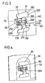
- the fastening of a part to be fastened to the support wall 40 with the described fastening element is shown schematically in FIG FIG. 4 shown.
- the part to be fastened is designated by the reference numeral 80 and rests on the front side 60 of the support wall 40 and is clamped with the stop member 20 on the support wall 40.
- the snap element 30 has a base plate 90 which is configured substantially rectangular. On two parallel side edges 100 and 110 of the base plate 90, two locking plates 120 and 130 are integrally formed. The two locking plates 120 and 130 have a distance from each other, which increases with increasing distance of the locking plates 120 and 130 of the base plate 90. When viewed in cross-section, the base plate 90 and the two locking plates 120 and 130 are thus approximately V-shaped. The upper distance A between the two locking plates 120 and 130 is dimensioned such that it is greater than the width B of the opening 50 in the support wall 40. So it applies A > B ,
- the cross-sectional area of the base plate 90 is chosen such that it is smaller or at most as large as the opening 50 of the support wall 40.
- the cross-sectional area of the base plate 90 is chosen such that it is smaller or at most as large as the opening 50 of the support wall 40.
- the two locking plates 120 and 130 will snap apart and thus cause a locking of the fastening element 10 in the opening 50.
- the two locking plates 120 and 130 thus form a snap element and prevent each other due to their distance A, a pulling out of the fastener 10 from the opening 50th
- the stop element 20 has for this purpose two stop plates 180 and 190 which rest for locking the fastening element 10 resiliently on the support wall 40.
- both stop plates 180 and 190 are each angled listed. Both stop plates each have a parallel partial plate 200 and 210, which is substantially parallel to the base plate 90 of the fastener 10 and parallel to the support wall 40.
- an angled sub-plate 220 and 230 are respectively formed and that at a predetermined angle. This angle is selected such that the two angled sub-plates 220 and 230 are oriented in the direction of the support wall 40 and the base plate 90, respectively.
- the two angled sub-panels 220 and 230 are pushed against the front side 60 of the support wall 40 and resiliently deflected until the two locking plates 120 and 130 are completely guided through the opening 50, snap apart and thus lock the fastener 10.
- the two angled sub-panels 220 and 230 thus cause a firm concern of the fastener 10 on the Trägewand 40, so that rattling of the fastener 10 is prevented on the support wall 40.
- the two angled sub-plates 220 and 230 are connected by means of the two parallel sub-plates 200 and 210 each having a connecting plate 240 and 241.
- the two connecting plates 240 and 241 are also respectively connected to the base plate 90, on parallel side edges 242 and 243 of the base plate 90th
- an unlocking element in the form of a tab or an unlocking bracket 250 or 260 is integrally formed on the two locking plates 120 and 130.
- the two unlocking brackets each extend from the end of the two locking plates 120 or 130 facing away from the base plate 90 through the opening 50 on the support wall 40 to the front side 60 of the support wall and are thus directly accessible from the outside.
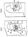
- FIGS. 7 and 8 show the unlocking of the fastener 10 by squeezing the two unlocking elements 250 and 260.
- the two arrows 310 and 320 indicate it, as on the two unlocking elements 250 and 260 force must be applied to get to unlocking.
- the fastener 10 in its unlocked position is in the FIG. 8 shown.
- the gas bag is thus the "part to be fastened", according to FIG. 4 designated by the reference numeral 80.
- the gas bag 80 has a tab 400 for attachment with a mounting hole 300, through which the fastener 10 is partially pushed.
- the size of the mounting hole 300 is selected such that only the snap element 30 of the fastening element 10 can be passed, whereas the stop element 20 is too large and thus can not pass through the opening hole 400. This is shown in particular by the FIGS. 10 and 11 in detail.
- the two stop plates 180 and 190 can be used to further fix the airbag 80 by inserting the two stop plates 180 and 190 into a shell of the gas bag through a slot 410.
- FIG. 12 the airbag 80 can be seen after the fastener 10 has been passed through the opening 300 and "hung" with the stop plates 180 and 190 in the shell of the airbag module.
- FIG. 13 shows a different view of the resulting assembly consisting of the fastener 10 and the airbag 80th
Landscapes
- Engineering & Computer Science (AREA)
- General Engineering & Computer Science (AREA)
- Mechanical Engineering (AREA)
- Connection Of Plates (AREA)
- Air Bags (AREA)
- Insertion Pins And Rivets (AREA)
Priority Applications (1)
| Application Number | Priority Date | Filing Date | Title |
|---|---|---|---|
| EP09168956.2A EP2123918B1 (de) | 2004-09-06 | 2005-08-25 | Befestigungselement |
Applications Claiming Priority (2)
| Application Number | Priority Date | Filing Date | Title |
|---|---|---|---|
| DE202004014219U DE202004014219U1 (de) | 2004-09-06 | 2004-09-06 | Befestigungselement |
| PCT/DE2005/001508 WO2006026956A1 (de) | 2004-09-06 | 2005-08-25 | Befestigungselement |
Related Child Applications (2)
| Application Number | Title | Priority Date | Filing Date |
|---|---|---|---|
| EP09168956.2A Division EP2123918B1 (de) | 2004-09-06 | 2005-08-25 | Befestigungselement |
| EP09168956.2A Division-Into EP2123918B1 (de) | 2004-09-06 | 2005-08-25 | Befestigungselement |
Publications (3)
| Publication Number | Publication Date |
|---|---|
| EP1787031A1 EP1787031A1 (de) | 2007-05-23 |
| EP1787031B1 EP1787031B1 (de) | 2009-09-30 |
| EP1787031B2 true EP1787031B2 (de) | 2015-11-04 |
Family
ID=33442399
Family Applications (2)
| Application Number | Title | Priority Date | Filing Date |
|---|---|---|---|
| EP05782810.5A Expired - Lifetime EP1787031B2 (de) | 2004-09-06 | 2005-08-25 | Befestigungselement |
| EP09168956.2A Revoked EP2123918B1 (de) | 2004-09-06 | 2005-08-25 | Befestigungselement |
Family Applications After (1)
| Application Number | Title | Priority Date | Filing Date |
|---|---|---|---|
| EP09168956.2A Revoked EP2123918B1 (de) | 2004-09-06 | 2005-08-25 | Befestigungselement |
Country Status (5)
| Country | Link |
|---|---|
| EP (2) | EP1787031B2 (enExample) |
| JP (1) | JP4809350B2 (enExample) |
| CN (2) | CN101761527B (enExample) |
| DE (2) | DE202004014219U1 (enExample) |
| WO (1) | WO2006026956A1 (enExample) |
Families Citing this family (33)
| Publication number | Priority date | Publication date | Assignee | Title |
|---|---|---|---|---|
| DE202004014219U1 (de) * | 2004-09-06 | 2004-11-11 | Takata-Petri (Ulm) Gmbh | Befestigungselement |
| US7861384B2 (en) | 2004-09-06 | 2011-01-04 | Takata-Petri Ag | Airbag arrangement and tools |
| DE102006011836B3 (de) * | 2006-03-15 | 2007-10-18 | Autoliv Development Ab | Befestigungselement |
| ITTO20060555A1 (it) * | 2006-07-26 | 2008-01-27 | Itw Automotive Italia S R L | Elemento di ritegno a molletta per elementi di finizione di veicoli, in particolare pannelli insonorizzanti |
| ATE548229T1 (de) * | 2006-07-31 | 2012-03-15 | Johnson Controls Gmbh | Fahrzeug-dachauskleidung mit integrierten kopf- seiten-airbag-modulen |
| DE102006040882B4 (de) * | 2006-08-31 | 2012-10-04 | Autoliv Development Ab | Vorhanggassack-Modul |
| DE102006041924A1 (de) | 2006-09-07 | 2008-03-27 | Volkswagen Ag | Befestigungsclip, insbesondere zur Befestigung eines Airbagmoduls in einem Fahrzeug, sowie Verfahren zur Befestigung eines Airbagmoduls |
| US7753402B2 (en) * | 2006-10-09 | 2010-07-13 | Key Safety Systems, Inc. | Air bag assembly and clip therefor |
| DE202006020693U1 (de) | 2006-12-27 | 2009-08-13 | Volkswagen Ag | Trägerwand mit einer Montageöffnung, insbesondere zum Halten eines Airbagmoduls in einem Fahrzeug |
| DE202007004549U1 (de) * | 2007-03-23 | 2007-06-28 | Takata-Petri Ag | Befestigungsanordnung sowie Werkzeug zum Verriegeln eines Befestigungselementes |
| DE202007015431U1 (de) * | 2007-10-30 | 2008-12-24 | Takata-Petri Ag | Airbageinrichtung zum Schutz eines Fahrzeuginsassen |
| DE102007060953A1 (de) * | 2007-12-18 | 2009-06-25 | Fischerwerke Gmbh & Co. Kg | Rastvorrichtung |
| US7837225B2 (en) * | 2008-05-14 | 2010-11-23 | Illinois Tool Works Inc. | Airbag fastener assembly |
| DE102008032964B4 (de) | 2008-07-09 | 2012-10-04 | Takata-Petri Ag | Gassackanordnung für ein Fahrzeuginsassen-Rückhaltesystem |
| DE102008034332B4 (de) | 2008-07-23 | 2024-02-08 | Zf Automotive Germany Gmbh | Fahrzeuginsassen-Schutzeinrichtung |
| DE102010008158A1 (de) | 2010-02-16 | 2011-08-18 | Volkswagen AG, 38440 | Befestigungsanordnung zur Befestigung eines Bauteils an einer Trägerwand sowie Befestigungselement hierfür |
| US9812684B2 (en) | 2010-11-09 | 2017-11-07 | GM Global Technology Operations LLC | Using elastic averaging for alignment of battery stack, fuel cell stack, or other vehicle assembly |
| DE102011004049B4 (de) | 2011-02-14 | 2017-01-19 | TAKATA Aktiengesellschaft | Vorrichtung zur Anordnung eines Befestigungselementes an einer Befestigungslasche eines Gassacks eines Fahrzeuginsassen-Rückhaltesystems |
| JP2012247001A (ja) * | 2011-05-27 | 2012-12-13 | Nifco Inc | クリップ |
| US9863454B2 (en) | 2013-08-07 | 2018-01-09 | GM Global Technology Operations LLC | Alignment system for providing precise alignment and retention of components of a sealable compartment |
| US20150052725A1 (en) * | 2013-08-22 | 2015-02-26 | GM Global Technology Operations LLC | Elastic averaging alignment system and method |
| US9511802B2 (en) | 2013-10-03 | 2016-12-06 | GM Global Technology Operations LLC | Elastically averaged alignment systems and methods |
| US9669774B2 (en) | 2013-10-11 | 2017-06-06 | GM Global Technology Operations LLC | Reconfigurable vehicle interior assembly |
| US9657807B2 (en) | 2014-04-23 | 2017-05-23 | GM Global Technology Operations LLC | System for elastically averaging assembly of components |
| CN104389870B (zh) * | 2014-10-27 | 2016-04-27 | 上海纳杰电气成套有限公司 | 一种弓形的卡式固定件 |
| US9758110B2 (en) | 2015-01-12 | 2017-09-12 | GM Global Technology Operations LLC | Coupling system |
| DE102015209111A1 (de) | 2015-03-30 | 2016-10-06 | Volkswagen Aktiengesellschaft | Befestigungsanordnung zur Befestigung eines Airbags an einer karosserieseitigen Trägerwand eines Fahrzeugs |
| US10252598B2 (en) * | 2015-06-23 | 2019-04-09 | Mahle International Gmbh | Air-conditioning system for a vehicle |
| DE102016120176A1 (de) * | 2016-10-24 | 2018-04-26 | Trw Automotive Gmbh | Gassackmodul |
| DE102017005352A1 (de) | 2017-05-29 | 2018-11-29 | A. Raymond Et Cie | Clip zum Befestigen eines ersten Elements an einem zweiten Element und Vorrichtung mit einem derartigen Clip |
| AU2019356905B2 (en) * | 2018-10-08 | 2025-04-10 | The Board Of Regents Of The University Of Oklahoma | System for mounting solar panels |
| CN109707713B (zh) * | 2019-01-28 | 2024-02-23 | 包玉龙 | 一种用于连接木制品相交构件的角码 |
| EP3754207B1 (en) * | 2019-06-17 | 2022-08-03 | Illinois Tool Works Inc. | Fastening clip |
Citations (6)
| Publication number | Priority date | Publication date | Assignee | Title |
|---|---|---|---|---|
| US4728068A (en) † | 1985-08-23 | 1988-03-01 | Ppmd, Inc. | Removable anchors for perforated panel hangers |
| DE4026922A1 (de) † | 1990-08-25 | 1992-04-30 | Raymond A Fa | Halteklammer zur befestigung von bauteilen an traegerplatten |
| US5539962A (en) † | 1994-10-25 | 1996-07-30 | Samsung Display Devices Co., Ltd. | Clip for coupling an inner shield with a frame |
| DE19607786A1 (de) † | 1996-03-01 | 1997-09-04 | Nokia Deutschland Gmbh | Verbindungselement |
| EP0908633A1 (en) † | 1997-04-22 | 1999-04-14 | Grupo Antolin-Ingenieria, S.A. | System for fixing accessories to panels and/or self-carrier elements for the internal lining of vehicles |
| EP1186787A1 (en) † | 2000-03-24 | 2002-03-13 | Grupo Antolin-Ingenieria, S.A. | Metal-plastic staple for fixing vehicle roofs and accessories to the body of a vehicle |
Family Cites Families (29)
| Publication number | Priority date | Publication date | Assignee | Title |
|---|---|---|---|---|
| US2300478A (en) | 1939-09-25 | 1942-11-03 | William R Wiley | Clip |
| US2631345A (en) | 1951-06-11 | 1953-03-17 | Illinois Tool Works | Double snap molding clip |
| US2692414A (en) | 1952-05-08 | 1954-10-26 | Illinois Tool Works | Snap-in stud fastener |
| US2698979A (en) | 1954-04-07 | 1955-01-11 | Tinnerman Products Inc | Molding clip or fastener |
| US2863195A (en) | 1955-12-22 | 1958-12-09 | Robert L Brown | Fastener |
| US2885754A (en) | 1956-12-05 | 1959-05-12 | Illinois Tool Works | Snap-in fastener |
| GB848100A (en) | 1957-05-30 | 1960-09-14 | Ft Products Ltd | An improved fastener |
| US3024509A (en) | 1958-07-11 | 1962-03-13 | Production Metal Stamping Comp | Fastening means and method of applying the same |
| US3080629A (en) | 1959-12-16 | 1963-03-12 | Gen Motors Corp | Moulding fastener |
| SE401653B (sv) * | 1972-06-21 | 1978-05-22 | Springfix Befestigungstechnik | Festklemma for lister med t-formig urtagning |
| US4630338A (en) | 1985-12-19 | 1986-12-23 | Usm Corporation | Molding clip |
| US5241727A (en) | 1990-12-24 | 1993-09-07 | Samsung Electron Devices Co., Ltd. | Clip for coupling inner shield with frame |
| US5759004A (en) | 1993-04-20 | 1998-06-02 | Panduit Corp. | MLT bent leg pushmount |
| US5651562A (en) | 1996-02-28 | 1997-07-29 | Trw Inc. | Release mechanism |
| JPH09265915A (ja) | 1996-03-29 | 1997-10-07 | Nec Kansai Ltd | インナーシールド結合用クランプ |
| ES2147493B1 (es) * | 1997-06-27 | 2001-03-01 | Mikalor Sa | Cabezal de fijacion de dos laminas metalicas superpuestas o grupo de ellas a unir entre si. |
| DE19812737A1 (de) * | 1998-03-24 | 1999-05-27 | Autoliv Dev | Seitenairbag mit Energieabsorptionselement |
| US6371512B1 (en) * | 1998-08-03 | 2002-04-16 | Toyota Jidosha Kabushiki Kaisha | Airbag apparatus for head-protecting |
| JP4225610B2 (ja) | 1998-08-27 | 2009-02-18 | 株式会社シブタニ | 部材の取付具 |
| JP4089086B2 (ja) * | 1999-06-02 | 2008-05-21 | 豊田合成株式会社 | エアバッグカバー |
| JP2001065517A (ja) | 1999-09-01 | 2001-03-16 | Ochiai:Kk | クリップ |
| JP2001277986A (ja) * | 2000-03-31 | 2001-10-10 | Piolax Inc | エアバッグ用のクリップ装置 |
| GB2367537B (en) * | 2000-10-03 | 2003-12-03 | Autoliv Dev | Improvements in or relating to an arrangement for mounting an inflatable element |
| WO2003033307A1 (es) | 2001-10-15 | 2003-04-24 | Grupo Antolin-Ingenieria, S.A. | Sistema de fijación de accesorios para el interior de vehículos |
| JP4177003B2 (ja) * | 2002-02-26 | 2008-11-05 | 株式会社イノアックコーポレーション | クリップ |
| US20040049894A1 (en) | 2002-06-24 | 2004-03-18 | Nicholas Jackson | Sheet metal fastening clip |
| JP4197437B2 (ja) * | 2003-01-23 | 2008-12-17 | 河西工業株式会社 | ピラートリムの取付構造 |
| DE102004017188B4 (de) * | 2004-04-07 | 2006-08-24 | Key Safety Systems, Inc., Sterling Heights | Befestigungselement für Airbagmodul |
| DE202004014219U1 (de) * | 2004-09-06 | 2004-11-11 | Takata-Petri (Ulm) Gmbh | Befestigungselement |
-
2004
- 2004-09-06 DE DE202004014219U patent/DE202004014219U1/de not_active Expired - Lifetime
-
2005
- 2005-08-25 WO PCT/DE2005/001508 patent/WO2006026956A1/de not_active Ceased
- 2005-08-25 CN CN2009102541665A patent/CN101761527B/zh not_active Expired - Fee Related
- 2005-08-25 EP EP05782810.5A patent/EP1787031B2/de not_active Expired - Lifetime
- 2005-08-25 JP JP2007528594A patent/JP4809350B2/ja not_active Expired - Fee Related
- 2005-08-25 CN CN200580025804A patent/CN100587278C/zh not_active Expired - Fee Related
- 2005-08-25 DE DE502005008248T patent/DE502005008248D1/de not_active Expired - Lifetime
- 2005-08-25 EP EP09168956.2A patent/EP2123918B1/de not_active Revoked
Patent Citations (6)
| Publication number | Priority date | Publication date | Assignee | Title |
|---|---|---|---|---|
| US4728068A (en) † | 1985-08-23 | 1988-03-01 | Ppmd, Inc. | Removable anchors for perforated panel hangers |
| DE4026922A1 (de) † | 1990-08-25 | 1992-04-30 | Raymond A Fa | Halteklammer zur befestigung von bauteilen an traegerplatten |
| US5539962A (en) † | 1994-10-25 | 1996-07-30 | Samsung Display Devices Co., Ltd. | Clip for coupling an inner shield with a frame |
| DE19607786A1 (de) † | 1996-03-01 | 1997-09-04 | Nokia Deutschland Gmbh | Verbindungselement |
| EP0908633A1 (en) † | 1997-04-22 | 1999-04-14 | Grupo Antolin-Ingenieria, S.A. | System for fixing accessories to panels and/or self-carrier elements for the internal lining of vehicles |
| EP1186787A1 (en) † | 2000-03-24 | 2002-03-13 | Grupo Antolin-Ingenieria, S.A. | Metal-plastic staple for fixing vehicle roofs and accessories to the body of a vehicle |
Also Published As
| Publication number | Publication date |
|---|---|
| CN101761527B (zh) | 2012-07-18 |
| EP2123918A3 (de) | 2010-05-05 |
| CN101761527A (zh) | 2010-06-30 |
| CN100587278C (zh) | 2010-02-03 |
| JP2008512285A (ja) | 2008-04-24 |
| EP1787031A1 (de) | 2007-05-23 |
| EP2123918A2 (de) | 2009-11-25 |
| DE202004014219U1 (de) | 2004-11-11 |
| CN101002030A (zh) | 2007-07-18 |
| WO2006026956A1 (de) | 2006-03-16 |
| JP4809350B2 (ja) | 2011-11-09 |
| EP1787031B1 (de) | 2009-09-30 |
| DE502005008248D1 (de) | 2009-11-12 |
| EP2123918B1 (de) | 2017-05-17 |
Similar Documents
| Publication | Publication Date | Title |
|---|---|---|
| EP1787031B2 (de) | Befestigungselement | |
| DE2936468C2 (de) | Vorrichtung zur Befestigung eines Instruments in einer Vertiefung der Armaturentafel eines Kraftfahrzeugs | |
| DE102012003617B4 (de) | Vorrichtung aus einem Gehäuse für ein Steuergerät und einem Befestigungselement | |
| DE102006013990A1 (de) | Befestigungsanordnung in einem Airbagmodul | |
| DE102017007060B4 (de) | Anordnung aus einer Vorrichtung zur Aufnahme eines Gegenstands in einem Kraftfahrzeug und einem Gegenstand | |
| DE102009013825A1 (de) | Steuerkastenanordnung mit einem Montageelement | |
| DE19948329C2 (de) | Schaltschrank sowie Verfahren zu seiner Herstellung | |
| DE29509360U1 (de) | Vorrichtung zum Befestigen eines mit einem plattenförmigen Teil versehenen Elementes an einer Wand in einem Gehäuse o.dgl. | |
| DE19510603A1 (de) | Aufrollautomat für einen Sicherheitsgurt | |
| EP2646288A1 (de) | Befestigungsvorrichtung für ein gassackmodul | |
| DE102019115093A1 (de) | Baugruppe für ein kraftfahrzeug mit einem sicherungsteil und sicherungsteil für eine derartige baugruppe | |
| DE102005051678A1 (de) | Vorrichtung zum Befestigen eines Anbauteiles an einem Trägerteil | |
| DE102016107858B4 (de) | Heckblendenanordnung eines Kraftfahrzeugs | |
| EP1769970B1 (de) | Befestigungssystem | |
| BE1031455B1 (de) | Halterahmen für einen Steckverbinder | |
| BE1032383B1 (de) | Halterahmen für einen Steckverbinder | |
| DE29514740U1 (de) | Elektrischer Steckverbinder | |
| DE102016015827B9 (de) | Rahmen für eine Sicherheitsgurteinrichtung, Set mit Rahmen und Anordnung mit einem Rahmen | |
| DE102023107157A1 (de) | Halterahmen für einen Steckverbinder | |
| DE202023105765U1 (de) | Verbinder für eine schraublose Verbindung einer Gittermatte an einen Zaunpfosten | |
| DE19750978A1 (de) | Rastverbindung zum Festlegen zweier Bauteile aneinander | |
| DE19747397B4 (de) | Befestigungsvorrichtung für die Befestigung eines Gerätes an einer Tragschiene | |
| DE60014964T2 (de) | Methode und einrichtung, um einen schlosszylinder zu befestigen | |
| EP2011668B1 (de) | Kennzeichenreiter | |
| EP1301678A1 (de) | Türrahmen mit steckbaren rahmenelementen |
Legal Events
| Date | Code | Title | Description |
|---|---|---|---|
| PUAI | Public reference made under article 153(3) epc to a published international application that has entered the european phase |
Free format text: ORIGINAL CODE: 0009012 |
|
| 17P | Request for examination filed |
Effective date: 20070314 |
|
| AK | Designated contracting states |
Kind code of ref document: A1 Designated state(s): DE FR GB SE |
|
| RIN1 | Information on inventor provided before grant (corrected) |
Inventor name: BAUMGARTNER, PETER |
|
| 17Q | First examination report despatched |
Effective date: 20071031 |
|
| DAX | Request for extension of the european patent (deleted) | ||
| RBV | Designated contracting states (corrected) |
Designated state(s): DE FR GB SE |
|
| GRAP | Despatch of communication of intention to grant a patent |
Free format text: ORIGINAL CODE: EPIDOSNIGR1 |
|
| GRAS | Grant fee paid |
Free format text: ORIGINAL CODE: EPIDOSNIGR3 |
|
| GRAA | (expected) grant |
Free format text: ORIGINAL CODE: 0009210 |
|
| AK | Designated contracting states |
Kind code of ref document: B1 Designated state(s): DE FR GB SE |
|
| REG | Reference to a national code |
Ref country code: GB Ref legal event code: FG4D Free format text: NOT ENGLISH |
|
| REF | Corresponds to: |
Ref document number: 502005008248 Country of ref document: DE Date of ref document: 20091112 Kind code of ref document: P |
|
| PG25 | Lapsed in a contracting state [announced via postgrant information from national office to epo] |
Ref country code: SE Free format text: LAPSE BECAUSE OF FAILURE TO SUBMIT A TRANSLATION OF THE DESCRIPTION OR TO PAY THE FEE WITHIN THE PRESCRIBED TIME-LIMIT Effective date: 20090930 |
|
| PLBI | Opposition filed |
Free format text: ORIGINAL CODE: 0009260 |
|
| 26 | Opposition filed |
Opponent name: ARAYMOND ET CIE. Effective date: 20100623 |
|
| PLAX | Notice of opposition and request to file observation + time limit sent |
Free format text: ORIGINAL CODE: EPIDOSNOBS2 |
|
| PLBB | Reply of patent proprietor to notice(s) of opposition received |
Free format text: ORIGINAL CODE: EPIDOSNOBS3 |
|
| GBPC | Gb: european patent ceased through non-payment of renewal fee |
Effective date: 20100825 |
|
| PG25 | Lapsed in a contracting state [announced via postgrant information from national office to epo] |
Ref country code: GB Free format text: LAPSE BECAUSE OF NON-PAYMENT OF DUE FEES Effective date: 20100825 |
|
| RAP2 | Party data changed (patent owner data changed or rights of a patent transferred) |
Owner name: TAKATA AG |
|
| APBM | Appeal reference recorded |
Free format text: ORIGINAL CODE: EPIDOSNREFNO |
|
| APBP | Date of receipt of notice of appeal recorded |
Free format text: ORIGINAL CODE: EPIDOSNNOA2O |
|
| APAH | Appeal reference modified |
Free format text: ORIGINAL CODE: EPIDOSCREFNO |
|
| APBQ | Date of receipt of statement of grounds of appeal recorded |
Free format text: ORIGINAL CODE: EPIDOSNNOA3O |
|
| REG | Reference to a national code |
Ref country code: DE Ref legal event code: R082 Ref document number: 502005008248 Country of ref document: DE Representative=s name: MAIKOWSKI & NINNEMANN PATENTANWAELTE, DE |
|
| REG | Reference to a national code |
Ref country code: DE Ref legal event code: R081 Ref document number: 502005008248 Country of ref document: DE Owner name: TAKATA AKTIENGESELLSCHAFT, DE Free format text: FORMER OWNER: TAKATA-PETRI AG, 63743 ASCHAFFENBURG, DE Effective date: 20120904 Ref country code: DE Ref legal event code: R082 Ref document number: 502005008248 Country of ref document: DE Representative=s name: MAIKOWSKI & NINNEMANN PATENTANWAELTE, DE Effective date: 20120904 Ref country code: DE Ref legal event code: R082 Ref document number: 502005008248 Country of ref document: DE Representative=s name: MAIKOWSKI & NINNEMANN PATENTANWAELTE PARTNERSC, DE Effective date: 20120904 |
|
| PLAB | Opposition data, opponent's data or that of the opponent's representative modified |
Free format text: ORIGINAL CODE: 0009299OPPO |
|
| R26 | Opposition filed (corrected) |
Opponent name: ARAYMOND ET CIE. Effective date: 20100623 |
|
| APBU | Appeal procedure closed |
Free format text: ORIGINAL CODE: EPIDOSNNOA9O |
|
| REG | Reference to a national code |
Ref country code: FR Ref legal event code: PLFP Year of fee payment: 11 |
|
| PLAB | Opposition data, opponent's data or that of the opponent's representative modified |
Free format text: ORIGINAL CODE: 0009299OPPO |
|
| R26 | Opposition filed (corrected) |
Opponent name: A. RAYMOND ET CIE Effective date: 20100623 |
|
| PUAH | Patent maintained in amended form |
Free format text: ORIGINAL CODE: 0009272 |
|
| STAA | Information on the status of an ep patent application or granted ep patent |
Free format text: STATUS: PATENT MAINTAINED AS AMENDED |
|
| 27A | Patent maintained in amended form |
Effective date: 20151104 |
|
| AK | Designated contracting states |
Kind code of ref document: B2 Designated state(s): DE FR GB SE |
|
| REG | Reference to a national code |
Ref country code: DE Ref legal event code: R102 Ref document number: 502005008248 Country of ref document: DE |
|
| PGFP | Annual fee paid to national office [announced via postgrant information from national office to epo] |
Ref country code: FR Payment date: 20150629 Year of fee payment: 11 |
|
| REG | Reference to a national code |
Ref country code: FR Ref legal event code: ST Effective date: 20170428 |
|
| PG25 | Lapsed in a contracting state [announced via postgrant information from national office to epo] |
Ref country code: FR Free format text: LAPSE BECAUSE OF NON-PAYMENT OF DUE FEES Effective date: 20160831 |
|
| PGFP | Annual fee paid to national office [announced via postgrant information from national office to epo] |
Ref country code: DE Payment date: 20171030 Year of fee payment: 13 |
|
| REG | Reference to a national code |
Ref country code: DE Ref legal event code: R119 Ref document number: 502005008248 Country of ref document: DE |
|
| PG25 | Lapsed in a contracting state [announced via postgrant information from national office to epo] |
Ref country code: DE Free format text: LAPSE BECAUSE OF NON-PAYMENT OF DUE FEES Effective date: 20190301 |