EP1764247A2 - Hecköffnungssystem für ein Kraftfahrzeug - Google Patents
Hecköffnungssystem für ein Kraftfahrzeug Download PDFInfo
- Publication number
- EP1764247A2 EP1764247A2 EP06019018A EP06019018A EP1764247A2 EP 1764247 A2 EP1764247 A2 EP 1764247A2 EP 06019018 A EP06019018 A EP 06019018A EP 06019018 A EP06019018 A EP 06019018A EP 1764247 A2 EP1764247 A2 EP 1764247A2
- Authority
- EP
- European Patent Office
- Prior art keywords
- opening system
- closure
- region
- frame device
- opening
- Prior art date
- Legal status (The legal status is an assumption and is not a legal conclusion. Google has not performed a legal analysis and makes no representation as to the accuracy of the status listed.)
- Granted
Links
- 210000000746 body region Anatomy 0.000 claims abstract description 18
- 238000005192 partition Methods 0.000 claims description 2
- 230000008878 coupling Effects 0.000 description 10
- 238000010168 coupling process Methods 0.000 description 10
- 238000005859 coupling reaction Methods 0.000 description 10
- 230000002411 adverse Effects 0.000 description 1
- 238000010276 construction Methods 0.000 description 1
- 230000001419 dependent effect Effects 0.000 description 1
- 238000011161 development Methods 0.000 description 1
- 230000018109 developmental process Effects 0.000 description 1
- 230000002093 peripheral effect Effects 0.000 description 1
Images

Classifications
-
- B—PERFORMING OPERATIONS; TRANSPORTING
- B60—VEHICLES IN GENERAL
- B60J—WINDOWS, WINDSCREENS, NON-FIXED ROOFS, DOORS, OR SIMILAR DEVICES FOR VEHICLES; REMOVABLE EXTERNAL PROTECTIVE COVERINGS SPECIALLY ADAPTED FOR VEHICLES
- B60J5/00—Doors
- B60J5/10—Doors arranged at the vehicle rear
- B60J5/101—Doors arranged at the vehicle rear for non-load transporting vehicles, i.e. family cars including vans
- B60J5/102—Doors arranged at the vehicle rear for non-load transporting vehicles, i.e. family cars including vans comprising door or part of door being pivotable downwards about horizontal axis to open position
- B60J5/104—Doors arranged at the vehicle rear for non-load transporting vehicles, i.e. family cars including vans comprising door or part of door being pivotable downwards about horizontal axis to open position where lower door part optionally moves independently, or follows as component the movement of the entire door structure, e.g. by being hinged in a door frame or releasably connected to upper door part
-
- B—PERFORMING OPERATIONS; TRANSPORTING
- B60—VEHICLES IN GENERAL
- B60J—WINDOWS, WINDSCREENS, NON-FIXED ROOFS, DOORS, OR SIMILAR DEVICES FOR VEHICLES; REMOVABLE EXTERNAL PROTECTIVE COVERINGS SPECIALLY ADAPTED FOR VEHICLES
- B60J5/00—Doors
- B60J5/10—Doors arranged at the vehicle rear
- B60J5/101—Doors arranged at the vehicle rear for non-load transporting vehicles, i.e. family cars including vans
- B60J5/105—Doors arranged at the vehicle rear for non-load transporting vehicles, i.e. family cars including vans comprising door or part of door being pivotable about vertical axis
Definitions
- the invention relates to a rear opening system for a motor vehicle according to the features of the preamble of claim 1.
- Such rear opening systems are used in almost every motor vehicle, in particular in motor vehicles with a storage space located in the rear of the motor vehicle.
- Rear opening systems which have an opening formed by a surrounding body in the rear region, rear doors or tailgates being arranged pivotably on the surrounding body in the region of the opening. Depending on the model, these tailgates or tailgates can then be pivoted about only one axis of rotation, either about a vertical axis or about a horizontal axis.
- the disadvantage occurs that opening the tailgates or rear doors is only possible about an axis of rotation and thus depending on the load optimal access and optimal storage of objects to be stored, especially of objects due to their space not completely in the space to find space, is not given.
- the invention includes the technical teaching that a rear opening system for a motor vehicle, a rear area with an opening to be closed by a body region, at least one closable with the rear area closure device with at least one closure element selected from the group comprising rear doors, tailgates and the like Opening or closing the opening of the rear area, wherein between the closure device and the rear area, a frame device is movably coupled to the rear area, via which the closure device is coupled to the rear area, in order to open or close the opening by moving the frame device and / or the closure element to realize.
- the frame device and closure device are each coupled via different joints.
- the joints preferably have an axis of rotation in the manner of a hinge, the axis of rotation preferably extending transversely to the vehicle longitudinal axis, for example vertically or horizontally. It is also conceivable, however, for the hinges to permit pivoting about an axis of rotation which is oriented in the direction of the longitudinal axis of the motor vehicle.
- the closure device to pivot about an axis of rotation.
- an oblique axis of rotation is conceivable which, for example, extends diagonally to allow diagonal pivoting.
- the frame device is also coupled by means of joints which, as described above, may have a rotational axis formed in different directions.
- the joints of the frame device on a formed in a different direction of rotation axis, as the joints of the closure elements.
- the closure elements are pivotable about a rotation axis in a first direction and the frame device is to be opened in a different direction via a second axis of rotation. This allows a maximum of flexibility in the opening of the rear portion of a motor vehicle.
- the motor vehicle can be designed both as station wagon, five-door vehicle, delivery van, sports car van and also mini-van, that is, as any motor vehicle with a corresponding tail construction.
- the rear region of the motor vehicle in this case has an opening which is surrounded by a body region and is thus formed by this.
- the closure device comprises at least one closure element which can be designed as a tailgate, tailgate, boot lid and the like.
- the closure device is coupled to the frame device.
- the frame device in turn is coupled to the body surrounding the opening.
- the coupling usually takes place via hinges or hinge elements. However, other couplings are possible, for example via a hinge.
- the frame device is preferably designed as a peripheral frame. This surrounds the entire to be closed Opening the rear area and is arranged on the body area.
- the frame is arranged on the body region so that it does not affect the overall impression of the motor vehicle and in particular does not protrude beyond the body.
- the frame is formed in one piece whereby a simple assembly can be ensured.
- the special arrangement of a flexible access of located in the rear area loading or storage space of the motor vehicle is possible, such as in narrow park conditions (underground parking, etc.), limited height conditions (garage ceiling, etc.) or for loading of small parts, where not the complete flap must be opened, guaranteed.
- the frame device is coupled via at least one first hinge element to the body region.
- a first hinge element is a safe, connected with little effort and known coupling of the frame device to the bodywork area possible.
- the hinge element can install without much space.
- the frame device is preferably coupled to the body region via at least two hinge elements.
- closure device is coupled to the frame device via at least one second hinge element.
- the coupling of the closure device to the frame device and the coupling of the frame device to the body region are independent of each other. In this respect, the coupling can be different in each case.
- the first hinge element is arranged on an upper or lower region of the body region, in order to realize a pivoting of the frame device upwards or downwards.
- This can the frame device together with the associated closure device as a whole are simply swung up or down.
- the upper part can be arranged in an upper region of the body region and the lower part in a lower part of the body region.
- the upper part can be opened upwards and the lower part opened downwards. This allows improved access to the cargo or storage space, especially in tight spaces.
- the first and / or the second hinge element is selected from the group of hinges comprising both turning and lifting hinges. These types of hinges are well known and ensure a reliable and secure coupling of the components to be coupled. In addition, the hinges build small, and are thus space-saving and the overall picture is not adversely applicable.
- closure device comprises a partition by at least two closure elements. This reduces the space required for opening or closing. In addition, a partial opening or closing is possible.
- An embodiment provides that the division of the closure device can be formed horizontally, vertically, symmetrically and / or asymmetrically. This makes it possible to design an individually adaptable closure device, which offers optimal access to the storage space depending on the load.
- the division can arbitrarily divide the closure device. Preference is given to a bipartition, which may also be formed with a central door joint.
- closure element as encompassing and / or as inserted closure element can be trained.
- the closure element can optically integrate well into the overall picture of the motor vehicle.
- each closure element is individually pivotally coupled to the frame device. In this way, only a single closure element of several can be opened as needed. This allows the best possible access to the storage or loading space. It is preferred that a motor vehicle comprises a rear area according to the present invention.
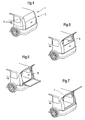
- FIG. 1 shows a section of a motor vehicle designed as a van with a rear opening system 1 according to the invention.
- FIG. 1 shows the rear area or the rear area 2 in which the rear opening system 1 according to the invention is arranged.
- the rear opening system 1 comprises the rear area 2, which has an opening (not shown here).
- the opening is bounded by a surrounding body area. Through this opening is an access from outside the vehicle to a located in the rear or rear area of the motor vehicle congestion or Cargo space given.
- this opening is closed by means of a closure device 3.
- the closure device 3 comprises two closure elements 4, which are designed here as rear doors.
- the closure device 3 is divided asymmetrically vertically, and thus has two unequal rear doors.
- the rear doors are hingedly coupled about a vertical axis of the hinges to a frame device as shown in FIG. 2 by means of hinges.
- FIG. 2 the rear opening system is shown open. Both rear doors are pivoted about their vertical axis to the outside, whereby access is provided through the opening 5 to the storage space or cargo space.
- the coupling of the movable parts of the rear opening system takes place essentially via joints 6.
- the frame device 7 is arranged on the body region surrounding the opening. The arrangement of the frame device 7 to the body portion via trained as hinge elements first joints 6a, as shown in Fig. 3 can be seen. The first joints have a horizontal axis of rotation over which the frame device 7 is pivotable.
- Fig. 2 is recognizable that the rear doors are arranged via two hinges designed as second hinges 6b rotatable about a vertical axis on a frame device.
- FIG. 3 the rear opening system is shown in a further open position.
- the individual closure elements 4 are pivoted about its axis of rotation, but designed as a comprehensive frame device frame device 7 is pivoted about a horizontal axis of rotation upwards and thus provides full access to the storage space of the vehicle.
- the frame or the frame device is connected by hinges in an upper region of the body region with this. In this opening case, the individual closure elements 4 need not be opened in order to allow full access to the storage or loading space of the vehicle.
- FIG. 4 shows now running as a combined motor vehicle.
- the rear opening system 1 in FIG. 4 likewise has a divided closure device 3, like the rear opening system illustrated in FIGS. 1 to 3, wherein in the present case the closure device 3 is divided horizontally asymmetrically and the closure elements 4 are designed as tailgates.
- Fig. 5 shows the rear opening system in a partially open position.
- the upper tailgate which is pivotally connected about a horizontal axis of rotation with the frame device, pivoted upwards.
- the lower tailgate is locked.
- the opening 5 is partially accessible, in particular so bulky items can be transported or invite in the car, which due to their space requirements can not otherwise be accommodated in the storage space of the vehicle.
- Fig. 6 shows the rear opening system according to the invention in a completely open position, wherein both tailgates are pivoted about their horizontal axes of rotation, and thus a full access through the opening 5 is ensured on the storage or cargo space.
- the upper tailgate which is pivotally coupled in the upper region of the rear region or the frame device, is pivoted upward as in FIG. 5.
- the lower tailgate which is pivotally coupled in a lower region of the rear region or of the frame device, is pivoted downwards.
- Fig. 7 shows the rear opening system also in a fully open position, but here the entire frame device 7 is pivoted about a horizontal axis of rotation upwards, the individual closure elements are not open. It would also be possible here for the frame device not to be coupled to the body region about a horizontally pivotable axis, but for a pivotable coupling to the body region to take place via a vertical axis of rotation. Also, a rotatable coupling is conceivable.
Landscapes
- Engineering & Computer Science (AREA)
- Mechanical Engineering (AREA)
- Body Structure For Vehicles (AREA)
- Power-Operated Mechanisms For Wings (AREA)
- Lock And Its Accessories (AREA)
- Motor Or Generator Cooling System (AREA)
Abstract
Description
- Die Erfindung betrifft ein Hecköffnungssystem für ein Kraftfahrzeug gemäß den Merkmalen des Oberbegriffs des Anspruchs 1.
- Derartige Hecköffnungssysteme kommen in nahezu jedem Kraftfahrzeug zum Einsatz, insbesondere bei Kraftfahrzeugen mit einem im Heck des Kraftfahrzeugs befindlichen Stauraum.
- Allgemein bekannt sind Hecköffnungssysteme, welche im Heckbereich eine durch eine umgebene Karosserie gebildete Öffnung aufweisen, wobei an der umgebenden Karosserie im Bereich der Öffnung schwenkbar Hecktüren oder Heckklappen angeordnet sind. Diese Heckklappen oder Hecktüren lassen sich dann je nach Ausführung nur um eine Drehachse aufschwenken, entweder um eine vertikale Achse oder um eine horizontale Achse.
- Bei der bekannten Lösung tritt der Nachteil auf, dass ein Öffnen der Heckklappen oder Hecktüren jeweils nur um eine Drehachse möglich ist und somit je nach Beladungsfall ein optimaler Zugang sowie eine optimale Lagerung von zu lagernden Objekten, insbesondere von Objekten die aufgrund ihres Platzbedarfes nicht komplett in dem Stauraum Platz finden, nicht gegeben ist.
- Es ist daher eine Aufgabe der vorliegenden Erfindung ein Hecköffnungssystem für Kraftfahrzeuge zu schaffen, bei dem ein oder mehrere Verschlusselemente wie Heckklappen oder Hecktüren um mehr als eine Drehachse zu öffnen sind.
- Diese Aufgabe wird von einem Hecköffnungssystem gemäß dem Oberbegriff des Anspruchs 1 in Verbindung mit dessen kennzeichnenden Merkmalen gelöst. Vorteilhafte Weiterbildung der Erfindung sind in den hierauf abhängigen Ansprüchen angegeben.
- Die Erfindung schließt die technische Lehre ein, dass ein Hecköffnungssystem für ein Kraftfahrzeug einen Heckbereich mit einer durch einen Karosseriebereich umgebenden, zu verschließenden Öffnung, mindestens eine mit dem Heckbereich koppelbare Verschlusseinrichtung mit mindestens einem Verschlusselement ausgewählt aus der Gruppe umfassend Hecktüren, Heckklappen und dergleichen, zum Öffnen bzw. Verschließen der Öffnung des Heckbereichs umfasst, wobei zwischen Verschlusseinrichtung und Heckbereich eine Rahmenvorrichtung bewegbar an dem Heckbereich gekoppelt angeordnet ist, über welchen die Verschlusseinrichtung mit dem Heckbereich gekoppelt ist, um ein Öffnen bzw. Verschließen der Öffnung über ein Bewegen der Rahmenvorrichtung und/oder des Verschlusselements zu realisieren.
- Diese Lösung bietet den Vorteil, dass Rahmenvorrichtung und Verschlusseinrichtung jeweils über verschiedene Gelenke gekoppelt sind. Die Gelenke weisen dabei vorzugsweise eine Drehachse nach Art eines Scharniers auf, wobei die Drehachse vorzugsweise quer zur Fahrzeuglängsachse verlaufen zum Beispiel vertikal oder horizontal. Denkbar ist aber auch, dass die Gelenke ein Öffnen Schwenken um eine Drehachse, welche in Richtung Kraftfahrzeuglängsachse ausgerichtet ist, ermöglichen. Somit ist die Verschlusseinrichtung um eine Drehachse schwenkbar zu öffnen. Auch ist eine schräge Drehachse vorstellbar, welche beispielsweise diagonal verläuft, um ein diagonales Schwenken zu ermöglichen. Die Rahmenvorrichtung ist ebenfalls über Gelenke gekoppelt, welche ähnlich wie zuvor beschrieben eine in verschiedene Richtungen ausgebildete Drehachse aufweisen können. Vorzugsweise weisen die Gelenke der Rahmenvorrichtung eine in eine andere Richtung ausgebildete Drehachse auf, als die Gelenke der Verschlusselemente. So sind die Verschlusselemente um eine Drehachse in eine erste Richtung schwenkbar und die Rahmenvorrichtung ist über eine zweite Drehachse in eine andere Richtung zu öffnen. Hierdurch wird ein Höchstmaß an Flexibilität bei der Öffnung des Heckbereichs eines Kraftfahrzeugs ermöglicht.
- Das Kraftfahrzeug kann sowohl als Kombi, Fünftürer, Lieferwagen, Sportwagen Van und auch Mini-Van ausgebildet sein, das heißt als jedes Kraftfahrzeug mit einer entsprechenden Heckbauweise.
- Der Heckbereich des Kraftfahrzeugs weist dabei eine Öffnung auf, welche von einem Karosseriebereich umgeben ist und somit durch diesen gebildet wird. Die Verschlusseinrichtung umfasst mindestens ein Verschlusselement, welches als Heckklappe, Hecktür, Kofferraumklappe und dergleichen ausgebildet sein kann. Die Verschlusseinrichtung ist mit der Rahmenvorrichtung gekoppelt. Die Rahmenvorrichtung wiederum ist mit den die Öffnung umgebenden Karosseriebereich gekoppelt. Die Kopplung erfolgt üblicherweise über Scharniere oder Scharnierelemente. Jedoch sind auch andere Kopplungen möglich, beispielsweise über ein Drehgelenk.
- Die Rahmenvorrichtung ist vorzugsweise als umlaufender Rahmen ausgebildet. Dieser umgibt die gesamte zu verschließende Öffnung des Heckbereichs und ist an dem Karosseriebereich angeordnet. Dabei ist der Rahmen an den Karosseriebereich so angeordnet, dass dieser den Gesamteindruck des Kraftfahrzeugs nicht beeinflusst und insbesondere nicht über die Karosserie hinausragt. Vorzugsweise ist der Rahmen einteilig ausgebildet wodurch sich eine einfache Montage gewährleisten lässt. Durch die spezielle Anordnung ist ein flexibler Zugang des im Heckbereich befindlichen Lade- oder Stauraums des Kraftfahrzeugs möglich, so z.B. in engen Parkzuständen (Tiefgarage etc.), eingeschränkten Höhenverhältnissen (Garagendecke etc.) oder zum Beladen von Kleinteilen, bei denen nicht die komplette Klappe geöffnet werden muss, gewährleistet.
- Bevorzugt ist, dass die Rahmenvorrichtung über mindestens ein erstes Scharnierelement an dem Karosseriebereich gekoppelt ist. Über ein erstes Scharnierelement ist eine sichere, mit wenig Aufwand verbundene und bekannte Ankopplung der Rahmenvorrichtung an dem Karosseriebereich möglich. Insbesondere lässt sich das Scharnierelement ohne hohen Platzbedarf anbringen. Vorzugsweise ist die Rahmenvorrichtung über mindestens zwei Scharnierelemente mit dem Karosseriebereich gekoppelt.
- Bevorzugt ist auch, dass die Verschlusseinrichtung über mindestens ein zweites Scharnierelement an die Rahmenvorrichtung gekoppelt ist. Hierdurch ist zum Einen die Kopplung der Verschlusseinrichtung an die Rahmenvorrichtung und die Kopplung der Rahmenvorrichtung an den Karosseriebereich unabhängig voneinander. Insofern lässt sich die Kopplung jeweils unterschiedlich gestalten.
- Weiter bevorzugt ist, dass das erste Scharnierelement an einem oberen bzw. unteren Bereich des Karosseriebereichs angeordnet ist, um ein Schwenken der Rahmenvorrichtung nach oben bzw. nach unten zu realisieren. Hierdurch kann die Rahmenvorrichtung mitsamt der damit verbundenen Verschlusseinrichtung als Gesamtes einfach nach oben bzw. nach unten geschwenkt werden. Bei einer Teilung der Verschlusseinrichtung, lässt sich der obere Teil in einem oberen Bereich des Karosseriebereichs anordnen und der untere Teil in einem unteren Teil des Karosseriebereichs. Somit lassen sich dann der obere Teil nach oben und der untere Teil nach unten aufklappen. Dies ermöglicht gerade in beengten Situationen einen verbesserten Zugang zum Lade- oder Stauraum. Zudem ist bevorzugt, dass das erste und/oder das zweite Scharnierelement ausgewählt ist aus der Gruppe der Scharniere umfassend eindrehende als auch aushebende Scharniere. Diese Scharnierarten sind allgemein bekannt und gewährleisten eine zuverlässige und sichere Kopplung der zu koppelnden Bauteile. Zudem bauen die Scharniere klein, und sind somit platzsparend und das Gesamtbild nicht beeinträchtigend einsetzbar.
- Auch bevorzugt ist, dass die Verschlusseinrichtung eine Teilung durch mindestens zwei Verschlusselemente umfasst. Hierdurch lässt sich der für das Öffnen bzw. Schließen benötigte Raum verringern. Zudem ist eine teilweise Öffnung bzw. Schließen möglich.
- Eine Ausführungsform sieht vor, dass die Teilung der Verschlusseinrichtung horizontal, vertikal, symmetrisch und/oder asymmetrisch ausgebildet sein kann. Hierdurch lässt sich eine individuell anpassbare Verschlusseinrichtung gestalten, welche je nach Beladungsfall einen optimalen Zugang zum Stauraum bietet. Die Teilung kann die Verschlusseinrichtung beliebig teilen. Bevorzugt ist eine Zweiteilung, wobei diese auch mit einer mittigen Türfuge ausgebildet sein kann.
- Bevorzugt ist auch, dass das Verschlusselement als umgreifendes und/oder als eingelegtes Verschlusselement ausbildbar ist. Somit lässt sich das Verschlusselement optisch gut in das Gesamtbild des Kraftfahrzeugs einbinden.
- Weiter bevorzugt ist, dass jedes Verschlusselement einzeln schwenkbar an der Rahmenvorrichtung gekoppelt ist. Auf diese Weise kann je nach Bedarf nur ein einzelnes Verschlusselement von mehreren geöffnet werden. Dies ermöglicht den bestmöglichen Zugang zum Stau- bzw. Laderaum. Bevorzugt ist, dass ein Kraftfahrzeug ein Heckbereich gemäß der vorliegenden Erfindung umfasst.
- Weitere die Erfindung verbessernde Maßnahmen sind in den Unteransprüchen angegeben oder werden nachstehend gemeinsam mit der Beschreibung eines oder mehrerer bevorzugter Ausführungsbeispiele der Erfindung anhand der Figuren näher dargestellt. Es zeigt:
- Fig. 1
- Einen Ausschnitt eines Kraftfahrzeugs (KFZ) des Typs Van in perspektivischer Ansicht mit zwei Hecktüren im verschlossenen Zustand,
- Fig. 2
- das KFZ gemäß Fig. 1 mit beiden Hecktüren geöffnet,
- Fig. 3
- das KFZ gemäß Fig. 1 mit nach oben geschwenktem Rahmen,
- Fig. 4
- einen Ausschnitt eines KFZ des Typs Kombi mit verschlossenem Heckbereich,
- Fig. 5
- das KFZ gemäß Fig. 4 mit einer nach oben geöffneten Heckklappe,
- Fig. 6
- das KFZ gemäß Fig. 4 mit beiden Heckklappen geöffnet und
- Fig. 7
- das KFZ gemäß Fig. 4 mit nach oben geschwenktem Rahmen.
- Fig. 1 zeigt einen Ausschnitt eines als Van ausgebildeten Kraftfahrzeugs mit einem erfindungsgemäßen Hecköffnungssystem 1. Insbesondere zeigt Fig. 1 den hinteren Bereich oder den Heckbereich 2, in dem das erfindungsgemäße Hecköffnungssystem 1 angeordnet ist.
Das Hecköffnungssystem 1 umfasst den Heckbereich 2, welcher eine Öffnung (hier nicht dargestellt) aufweist. Die Öffnung wird durch einen umgebenen Karosseriebereich begrenzt. Durch diese Öffnung ist ein Zugriff von außerhalb des KFZ auf einen im hinteren Teil oder Heckbereich des Kraftfahrzeugs befindlichen Stau- oder
Laderaum gegeben. In Fig. 1 ist diese Öffnung mittels einer Verschlusseinrichtung 3 verschlossen. Die Verschlusseinrichtung 3 umfasst vorliegend zwei Verschlusselemente 4, welche hier als Hecktüren ausgebildet sind. Dabei ist die Verschlusseinrichtung 3 asymmetrisch vertikal geteilt, und weist somit zwei ungleiche Hecktüren auf. Die Hecktüren sind mittels Scharnieren drehbar um eine vertikale Achse der Scharniere mit einer Rahmenvorrichtung wie in Fig. 2 dargestellt gekoppelt. - In Fig. 2 ist das Hecköffnungssystem geöffnet dargestellt. Beide Hecktüren sind um ihre vertikale Achse nach außen geschwenkt, wodurch ein Zugriff durch die Öffnung 5 zum Stauraum bzw. Laderaum gegeben ist. Die Kopplung der bewegbaren Teile des Hecköffnungssystems erfolgt im Wesentlichen über Gelenke 6. Die Rahmenvorrichtung 7 ist an dem die Öffnung umgebenden Karosseriebereich angeordnet. Die Anordnung der Rahmenvorrichtung 7 an den Karosseriebereich erfolgt über als Scharnierelemente ausgebildete erste Gelenke 6a, wie in Fig. 3 ersichtlich. Die ersten Gelenke weisen eine horizontale Drehachse auf, über welche die Rahmenvorrichtung 7 schwenkbar ist. In Fig. 2 ist erkennbar, dass die Hecktüren über zwei als Scharniere ausgebildete zweite Gelenke 6b drehbar um eine vertikale Achse an einer Rahmenvorrichtung angeordnet sind.
- In Fig. 3 ist das Hecköffnungssystem in einer weiteren geöffneten Position dargestellt. Hier sind jedoch nicht die einzelnen Verschlusselemente 4 um ihre Drehachse geschwenkt, sondern die als umfassende Rahmenvorrichtung ausgebildete Rahmenvorrichtung 7 ist um eine horizontale Drehachse nach oben geschwenkt und bietet so vollen Zugriff auf den Stauraum des KFZ. Der Rahmen bzw. die Rahmenvorrichtung ist über Scharniere in einem oberen Bereich des Karosseriebereichs mit diesem verbunden. Bei diesem Öffnungsfall müssen die einzelnen Verschlusselemente 4 nicht geöffnet werden, um einen vollen Zugriff auf den Stau- bzw. Laderaum des KFZ zu ermöglichen.
- Fig. 4 zeigt nun ein als Kombi ausgeführtes Kraftfahrzeug. Das Hecköffnungssystem 1 in Fig. 4 weist ebenfalls wie das in Fig. 1 bis 3 dargestellte Hecköffnungssystem eine geteilte Verschlusseinrichtung 3 auf, wobei vorliegend die Verschlusseinrichtung 3 horizontal asymmetrisch geteilt ist und die Verschlusselemente 4 als Heckklappen ausgebildet sind.
- Fig. 5 zeigt das Hecköffnungssystem in einer teilweise geöffneten Position. Hierbei ist die obere Heckklappe, welche um eine horizontale Drehachse schwenkbar mit der Rahmenvorrichtung verbunden ist, nach oben geschwenkt. Die untere Heckklappe ist verschlossen. Auf diese Weise ist die Öffnung 5 zum Teil zugänglich, insbesondere lassen sich so sperrige Gegenstände in dem KFZ transportieren oder einladen, welche aufgrund ihres Platzbedarfes ansonsten nicht in dem Stauraum des KFZ untergebracht werden können.
- Fig. 6 zeigt das erfindungsgemäße Hecköffnungssystem in einer komplett geöffneten Position, wobei beide Heckklappen um ihre horizontalen Drehachsen geschwenkt sind, und somit ein voller Zugriff durch die Öffnung 5 auf den Stau- bzw. Laderaum gewährleistet ist. Die obere Heckklappe, welche im oberen Bereich des Heckbereichs bzw. der Rahmenvorrichtung gelenkig gekoppelt ist, ist dabei wie in Fig. 5 nach oben geschwenkt. Die untere Heckklappe, welche in einem unteren Bereich des Heckbereichs bzw. der Rahmenvorrichtung gelenkig gekoppelt ist, ist nach unten geschwenkt.
- Fig. 7 zeigt das Hecköffnungssystem ebenfalls in einer komplett geöffneten Position, wobei hier jedoch die gesamte Rahmenvorrichtung 7 um eine horizontale Drehachse nach oben geschwenkt ist, wobei die einzelnen Verschlusselemente nicht geöffnet sind. Möglich wäre hier auch, dass die Rahmenvorrichtung nicht um eine horizontal schwenkbare Achse an den Karosseriebereich gekoppelt ist, sondern dass eine schwenkbare Kopplung an den Karosseriebereich über eine senkrechte Drehachse erfolgen könnte. Auch ist eine drehbare Kopplung denkbar.
-
- 1
- Hecköffnungssystem
- 2
- Heckbereich
- 3
- Verschlusseinrichtung
- 4
- Verschlusselemente
- 5
- Öffnung
- 6
- Gelenke
- 6 a
- erste Gelenke
- 6 b
- zweite Gelenke
- 7
- Rahmenvorrichtung
Claims (11)
- Hecköffnungssystem (1) für ein Kraftfahrzeug, umfassend
einen Heckbereich (2) mit einer durch einen Karosseriebereich umgebenden, zu verschließenden Öffnung (5),
mindestens eine mit dem Heckbereich (2) koppelbare Verschlusseinrichtung (3) mit mindestens einem Verschlusselement (4) ausgewählt aus der Gruppe umfassend Hecktüren, Heckklappen und dergleichen, zum Öffnen bzw. Verschließen der Öffnung (5) des Heckbereichs,
dadurch gekennzeichnet, dass
zwischen Verschlusseinrichtung (3) und Heckbereich (2) eine Rahmenvorrichtung (7) bewegbar an dem Heckbereich (2) gekoppelt angeordnet ist, über welchen die Verschlusseinrichtung (3) mit dem Heckbereich (2) gekoppelt ist, um ein Öffnen bzw. Verschließen der Öffnung (5) über ein Bewegen der Rahmenvorrichtung (7) und/oder des Verschlusselements (4) zu realisieren. - Hecköffnungssystem (1) nach Anspruch 1,
dadurch gekennzeichnet, dass
die Rahmenvorrichtung (7) über mindestens ein erstes Gelenk (6, 6a) umfassend Scharnierelemente und dergleichen bewegbar an den Karosseriebereich gekoppelt ist. - Hecköffnungssystem (1) nach Anspruch 1 oder 2,
dadurch gekennzeichnet, dass
die Verschlusseinrichtung (3) über mindestens ein zweites Gelenk (6, 6b) umfassend Scharnierelemente und dergleichen bewegbar an die Rahmenvorrichtung (7) gekoppelt ist. - Hecköffnungssystem (1) nach einem der vorherigen Ansprüche 1 bis 3,
dadurch gekennzeichnet, dass
das erste Gelenk (6a) als Scharnierelement ausgebildet ist, welches an einem oberen bzw. unteren Bereich des Karosseriebereichs angeordnet ist, um ein Schwenken der Rahmenvorrichtung (7) nach oben bzw. nach unten zu realisieren. - Hecköffnungssystem (1) nach einem der vorherigen Ansprüche 1 bis 4,
dadurch gekennzeichnet, dass
das zweite Gelenk (6b) als Scharnierelement ausgebildet ist, welches an einem seitlichen Bereich des Karosseriebereichs angeordnet ist, um ein Schwenken der Rahmenvorrichtung (7) zur Seite zu realisieren. - Hecköffnungssystem (1) nach einem der vorherigen Ansprüche 1 bis 5,
dadurch gekennzeichnet, dass
das erste und/oder das zweite Scharnierelement (6a, 6b) ausgewählt ist aus der Gruppe der Scharniere umfassend eindrehende als auch aushebende Scharniere. - Hecköffnungssystem (1) nach einem der vorherigen Ansprüche 1 bis 6,
dadurch gekennzeichnet, dass
die Verschlusseinrichtung (3) eine Teilung durch mindestens zwei Verschlusselemente (4) umfasst. - Hecköffnungssystem (1) nach einem der vorherigen Ansprüche 1 bis 7,
dadurch gekennzeichnet, dass
die Teilung der Verschlusseinrichtung (3) horizontal, vertikal, symmetrisch und/oder asysmmetrisch ausgebildet sein kann. - Hecköffnungssystem (1) nach einem der vorherigen Ansprüche 1 bis 8,
dadurch gekennzeichnet, dass
das Verschlusselement (4) als umgreifendes und/oder als eingelegtes Verschlusselement () ausgebildet ist. - Hecköffnungssystem (1) nach einem der vorherigen Ansprüche 1 bis 9,
dadurch gekennzeichnet, dass
jedes Verschlusselement (4) einzeln bewegbar an der Rahmenvorrichtung (7) gekoppelt ist. - Kraftfahrzeug umfassend einen Hecköffnungssystem (1) gemäß einem der vorherigen Ansprüche 1 bis 10.
Applications Claiming Priority (1)
| Application Number | Priority Date | Filing Date | Title |
|---|---|---|---|
| DE102005044569A DE102005044569B4 (de) | 2005-09-17 | 2005-09-17 | Hecköffnungssystem |
Publications (3)
| Publication Number | Publication Date |
|---|---|
| EP1764247A2 true EP1764247A2 (de) | 2007-03-21 |
| EP1764247A3 EP1764247A3 (de) | 2008-01-16 |
| EP1764247B1 EP1764247B1 (de) | 2009-10-28 |
Family
ID=37546366
Family Applications (1)
| Application Number | Title | Priority Date | Filing Date |
|---|---|---|---|
| EP06019018A Not-in-force EP1764247B1 (de) | 2005-09-17 | 2006-09-12 | Hecköffnungssystem für ein Kraftfahrzeug |
Country Status (3)
| Country | Link |
|---|---|
| EP (1) | EP1764247B1 (de) |
| AT (1) | ATE446869T1 (de) |
| DE (2) | DE102005044569B4 (de) |
Cited By (17)
| Publication number | Priority date | Publication date | Assignee | Title |
|---|---|---|---|---|
| DE102007052620A1 (de) | 2007-11-05 | 2009-05-07 | GM Global Technology Operations, Inc., Detroit | Kraftfahrzeug mit optionalem Hecköffnungsrahmen |
| DE102007056853A1 (de) | 2007-11-26 | 2009-05-28 | GM Global Technology Operations, Inc., Detroit | Feststeller für das Verschlusselement einer Kfz-Hecköffnung |
| DE102008020090A1 (de) | 2008-04-22 | 2009-10-29 | GM Global Technology Operations, Inc., Detroit | Kraftfahrzeug mit Hecköffnung |
| WO2011073260A1 (de) * | 2009-12-17 | 2011-06-23 | Bayerische Motoren Werke Aktiengesellschaft | Erste und zweite gruppe von fahrzeugen |
| EP2386435A1 (de) * | 2010-05-10 | 2011-11-16 | Tofas Turk Otomobil Fabrikasi Anonim Sirketi | Nutzfahrzeug mit Türanordnung |
| WO2014175243A1 (ja) * | 2013-04-23 | 2014-10-30 | 本田技研工業株式会社 | 車両 |
| WO2014175241A1 (ja) * | 2013-04-23 | 2014-10-30 | 本田技研工業株式会社 | 車両 |
| CN104411522A (zh) * | 2012-07-04 | 2015-03-11 | 本田技研工业株式会社 | 带尾门的车辆 |
| JP2015127165A (ja) * | 2013-12-27 | 2015-07-09 | 本田技研工業株式会社 | テールゲート付き車体構造 |
| US20160101764A1 (en) * | 2013-06-04 | 2016-04-14 | Honda Motor Co., Ltd. | Vehicle |
| US20160114661A1 (en) * | 2014-10-22 | 2016-04-28 | Honda Motor Co., Ltd. | Vehicle body structure |
| JP2016084096A (ja) * | 2014-10-28 | 2016-05-19 | 本田技研工業株式会社 | テールゲート付き車体構造 |
| JPWO2014175240A1 (ja) * | 2013-04-23 | 2017-02-23 | 本田技研工業株式会社 | 車両 |
| JPWO2014175238A1 (ja) * | 2013-04-23 | 2017-02-23 | 本田技研工業株式会社 | 車両 |
| FR3067986A1 (fr) * | 2017-06-27 | 2018-12-28 | Renault S.A.S | Mecanisme pour un coffre a deux ouvrants d'un vehicule automobile |
| CN115489279A (zh) * | 2022-08-29 | 2022-12-20 | 重庆长安汽车股份有限公司 | 一种汽车多功能背门系统总成及车辆 |
| US20250115100A1 (en) * | 2023-10-10 | 2025-04-10 | Rivian Ip Holdings, Llc | Operating dual closures utilizing a common system |
Families Citing this family (4)
| Publication number | Priority date | Publication date | Assignee | Title |
|---|---|---|---|---|
| DE102007033929B4 (de) | 2006-09-20 | 2022-01-05 | Volkswagen Ag | Kraftfahrzeugkarosserie |
| DE102007020916A1 (de) | 2007-05-04 | 2008-11-06 | GM Global Technology Operations, Inc., Detroit | Kraftfahrzeugheck |
| DE102008018333A1 (de) * | 2008-04-11 | 2009-10-15 | GM Global Technology Operations, Inc., Detroit | Verschlusselement für eine Kraftfahrzeugöffnung |
| WO2015098613A1 (ja) * | 2013-12-27 | 2015-07-02 | 本田技研工業株式会社 | 車両 |
Citations (1)
| Publication number | Priority date | Publication date | Assignee | Title |
|---|---|---|---|---|
| US20040174035A1 (en) | 2003-03-07 | 2004-09-09 | Acker John R. | Vehicle endgate with integral door |
Family Cites Families (5)
| Publication number | Priority date | Publication date | Assignee | Title |
|---|---|---|---|---|
| US1828450A (en) * | 1929-11-21 | 1931-10-20 | Charles M Shaffer | End gate for trucks and other vehicles |
| US3387406A (en) * | 1966-08-24 | 1968-06-11 | Ford Motor Co | Dual-hinged tailgate |
| DE19615540A1 (de) * | 1996-04-19 | 1997-04-30 | Daimler Benz Ag | Personenkraftwagen mit wenigstens einem schwenkbar gelagerten Karosserieteil, insbesondere einer Heckklappe |
| US6742826B2 (en) * | 2001-08-08 | 2004-06-01 | J.R. Kennedy Co., Ltd. | Five position tailgate assembly |
| DE10203538A1 (de) * | 2002-01-29 | 2003-08-07 | Webasto Vehicle Sys Int Gmbh | Kraftfahrzeug mit einem Laderaum und einer Laderaumtür |
-
2005
- 2005-09-17 DE DE102005044569A patent/DE102005044569B4/de not_active Expired - Lifetime
-
2006
- 2006-09-12 EP EP06019018A patent/EP1764247B1/de not_active Not-in-force
- 2006-09-12 AT AT06019018T patent/ATE446869T1/de active
- 2006-09-12 DE DE502006005231T patent/DE502006005231D1/de active Active
Patent Citations (1)
| Publication number | Priority date | Publication date | Assignee | Title |
|---|---|---|---|---|
| US20040174035A1 (en) | 2003-03-07 | 2004-09-09 | Acker John R. | Vehicle endgate with integral door |
Cited By (27)
| Publication number | Priority date | Publication date | Assignee | Title |
|---|---|---|---|---|
| DE102007052620A1 (de) | 2007-11-05 | 2009-05-07 | GM Global Technology Operations, Inc., Detroit | Kraftfahrzeug mit optionalem Hecköffnungsrahmen |
| DE102007056853A1 (de) | 2007-11-26 | 2009-05-28 | GM Global Technology Operations, Inc., Detroit | Feststeller für das Verschlusselement einer Kfz-Hecköffnung |
| DE102008020090A1 (de) | 2008-04-22 | 2009-10-29 | GM Global Technology Operations, Inc., Detroit | Kraftfahrzeug mit Hecköffnung |
| WO2011073260A1 (de) * | 2009-12-17 | 2011-06-23 | Bayerische Motoren Werke Aktiengesellschaft | Erste und zweite gruppe von fahrzeugen |
| EP2386435A1 (de) * | 2010-05-10 | 2011-11-16 | Tofas Turk Otomobil Fabrikasi Anonim Sirketi | Nutzfahrzeug mit Türanordnung |
| EP2871084A4 (de) * | 2012-07-04 | 2016-06-01 | Honda Motor Co Ltd | Fahrzeug mit heckklappe |
| US9409467B2 (en) * | 2012-07-04 | 2016-08-09 | Honda Motor Co., Ltd. | Vehicle with tail gate |
| CN104411522A (zh) * | 2012-07-04 | 2015-03-11 | 本田技研工业株式会社 | 带尾门的车辆 |
| US20150183307A1 (en) * | 2012-07-04 | 2015-07-02 | Honda Motor Co., Ltd. | Vehicle with tail gate |
| JPWO2014175238A1 (ja) * | 2013-04-23 | 2017-02-23 | 本田技研工業株式会社 | 車両 |
| WO2014175243A1 (ja) * | 2013-04-23 | 2014-10-30 | 本田技研工業株式会社 | 車両 |
| US9738141B2 (en) | 2013-04-23 | 2017-08-22 | Honda Motor Co., Ltd. | Vehicle |
| JPWO2014175243A1 (ja) * | 2013-04-23 | 2017-02-23 | 本田技研工業株式会社 | 車両 |
| JPWO2014175240A1 (ja) * | 2013-04-23 | 2017-02-23 | 本田技研工業株式会社 | 車両 |
| WO2014175241A1 (ja) * | 2013-04-23 | 2014-10-30 | 本田技研工業株式会社 | 車両 |
| US9505291B2 (en) | 2013-04-23 | 2016-11-29 | Honda Motor Co., Ltd. | Vehicle |
| JPWO2014175241A1 (ja) * | 2013-04-23 | 2017-02-23 | 本田技研工業株式会社 | 車両 |
| US20160101764A1 (en) * | 2013-06-04 | 2016-04-14 | Honda Motor Co., Ltd. | Vehicle |
| US9809203B2 (en) * | 2013-06-04 | 2017-11-07 | Honda Motor Co., Ltd. | Vehicle |
| JP2015127165A (ja) * | 2013-12-27 | 2015-07-09 | 本田技研工業株式会社 | テールゲート付き車体構造 |
| US9669687B2 (en) * | 2014-10-22 | 2017-06-06 | Honda Motor Co., Ltd. | Vehicle body structure |
| US20160114661A1 (en) * | 2014-10-22 | 2016-04-28 | Honda Motor Co., Ltd. | Vehicle body structure |
| JP2016084096A (ja) * | 2014-10-28 | 2016-05-19 | 本田技研工業株式会社 | テールゲート付き車体構造 |
| FR3067986A1 (fr) * | 2017-06-27 | 2018-12-28 | Renault S.A.S | Mecanisme pour un coffre a deux ouvrants d'un vehicule automobile |
| CN115489279A (zh) * | 2022-08-29 | 2022-12-20 | 重庆长安汽车股份有限公司 | 一种汽车多功能背门系统总成及车辆 |
| US20250115100A1 (en) * | 2023-10-10 | 2025-04-10 | Rivian Ip Holdings, Llc | Operating dual closures utilizing a common system |
| US12522055B2 (en) * | 2023-10-10 | 2026-01-13 | Rivian Ip Holdings, Llc | Operating dual closures utilizing a common system |
Also Published As
| Publication number | Publication date |
|---|---|
| DE502006005231D1 (de) | 2009-12-10 |
| DE102005044569A1 (de) | 2007-03-29 |
| EP1764247A3 (de) | 2008-01-16 |
| ATE446869T1 (de) | 2009-11-15 |
| DE102005044569B4 (de) | 2013-01-03 |
| EP1764247B1 (de) | 2009-10-28 |
Similar Documents
| Publication | Publication Date | Title |
|---|---|---|
| EP1764247B1 (de) | Hecköffnungssystem für ein Kraftfahrzeug | |
| EP3501467B1 (de) | Kraftfahrzeug umfassend eine schiebetüre | |
| DE102009016275B3 (de) | Heckklappenscharnier für Kraftfahrzeug mit zwei Schwenkachsen | |
| DE102015012144B4 (de) | Befestigungsvorrichtung zum Lagern und Bewegen wenigstens einer Fahrzeugtür an einem Kraftfahrzeug | |
| DE102008020090A1 (de) | Kraftfahrzeug mit Hecköffnung | |
| DE202018106610U1 (de) | Fahrzeugtürbaugruppen | |
| DE102022210611A1 (de) | Türscharniervorrichtung für fahrzeuge | |
| DE10322977B4 (de) | Fahrzeugkarosseriekonstruktion | |
| DE102022210914A1 (de) | Türgelenkvorrichtung für fahrzeuge | |
| DE102018219092A1 (de) | Tür für ein Fahrzeug und korrespondierendes Fahrzeug | |
| DE102019114940A1 (de) | Scharnierbasierter Ausgleichsmechanismus | |
| DE19649743B4 (de) | Schließeinrichtung für einen Deckel mit einer Schloßbolzenabdeckung | |
| DE202007018286U1 (de) | Horizontal geteilte Fahrzeugheckklappe | |
| DE19641360C2 (de) | Kraftfahrzeug mit einer Heckklappe | |
| DE102005059413A1 (de) | Gelenk für eine Tür eines Kraftfahrzeugs | |
| DE102007036926A1 (de) | Hutablage für ein Kraftfahrzeug | |
| DE102004059501B3 (de) | Fahrzeugtür für Kraftfahrzeuge | |
| DE102007007064A1 (de) | Schließanordnung für einen Fahrzeugbau | |
| DE102023126886A1 (de) | Schiebetürvorrichtung für fahrzeug | |
| DE102007002663B4 (de) | Türanordnung an einem Kraftwagen | |
| DE102014208166A1 (de) | Schiebeverdeckstruktur | |
| DE102007002573B4 (de) | Türanordnung an einem Kraftwagen | |
| WO2009015756A1 (de) | Heckklappenanordnung für einen personenkraftwagen | |
| EP2054254A1 (de) | Kraftfahrzeug mit einem kofferraum | |
| DE102024132798A1 (de) | Spannvorrichtung für türschlösser in fahrzeugen |
Legal Events
| Date | Code | Title | Description |
|---|---|---|---|
| PUAI | Public reference made under article 153(3) epc to a published international application that has entered the european phase |
Free format text: ORIGINAL CODE: 0009012 |
|
| AK | Designated contracting states |
Kind code of ref document: A2 Designated state(s): AT BE BG CH CY CZ DE DK EE ES FI FR GB GR HU IE IS IT LI LT LU LV MC NL PL PT RO SE SI SK TR |
|
| AX | Request for extension of the european patent |
Extension state: AL BA HR MK YU |
|
| PUAL | Search report despatched |
Free format text: ORIGINAL CODE: 0009013 |
|
| AK | Designated contracting states |
Kind code of ref document: A3 Designated state(s): AT BE BG CH CY CZ DE DK EE ES FI FR GB GR HU IE IS IT LI LT LU LV MC NL PL PT RO SE SI SK TR |
|
| AX | Request for extension of the european patent |
Extension state: AL BA HR MK YU |
|
| 17P | Request for examination filed |
Effective date: 20080716 |
|
| 17Q | First examination report despatched |
Effective date: 20080818 |
|
| AKX | Designation fees paid |
Designated state(s): AT BE BG CH CY CZ DE DK EE ES FI FR GB GR HU IE IS IT LI LT LU LV MC NL PL PT RO SE SI SK TR |
|
| GRAP | Despatch of communication of intention to grant a patent |
Free format text: ORIGINAL CODE: EPIDOSNIGR1 |
|
| GRAS | Grant fee paid |
Free format text: ORIGINAL CODE: EPIDOSNIGR3 |
|
| GRAA | (expected) grant |
Free format text: ORIGINAL CODE: 0009210 |
|
| AK | Designated contracting states |
Kind code of ref document: B1 Designated state(s): AT BE BG CH CY CZ DE DK EE ES FI FR GB GR HU IE IS IT LI LT LU LV MC NL PL PT RO SE SI SK TR |
|
| REG | Reference to a national code |
Ref country code: GB Ref legal event code: FG4D Free format text: NOT ENGLISH |
|
| REG | Reference to a national code |
Ref country code: CH Ref legal event code: EP |
|
| REG | Reference to a national code |
Ref country code: IE Ref legal event code: FG4D |
|
| REF | Corresponds to: |
Ref document number: 502006005231 Country of ref document: DE Date of ref document: 20091210 Kind code of ref document: P |
|
| LTIE | Lt: invalidation of european patent or patent extension |
Effective date: 20091028 |
|
| NLV1 | Nl: lapsed or annulled due to failure to fulfill the requirements of art. 29p and 29m of the patents act | ||
| PG25 | Lapsed in a contracting state [announced via postgrant information from national office to epo] |
Ref country code: LT Free format text: LAPSE BECAUSE OF FAILURE TO SUBMIT A TRANSLATION OF THE DESCRIPTION OR TO PAY THE FEE WITHIN THE PRESCRIBED TIME-LIMIT Effective date: 20091028 Ref country code: SE Free format text: LAPSE BECAUSE OF FAILURE TO SUBMIT A TRANSLATION OF THE DESCRIPTION OR TO PAY THE FEE WITHIN THE PRESCRIBED TIME-LIMIT Effective date: 20091028 Ref country code: PT Free format text: LAPSE BECAUSE OF FAILURE TO SUBMIT A TRANSLATION OF THE DESCRIPTION OR TO PAY THE FEE WITHIN THE PRESCRIBED TIME-LIMIT Effective date: 20100301 Ref country code: IS Free format text: LAPSE BECAUSE OF FAILURE TO SUBMIT A TRANSLATION OF THE DESCRIPTION OR TO PAY THE FEE WITHIN THE PRESCRIBED TIME-LIMIT Effective date: 20100228 Ref country code: ES Free format text: LAPSE BECAUSE OF FAILURE TO SUBMIT A TRANSLATION OF THE DESCRIPTION OR TO PAY THE FEE WITHIN THE PRESCRIBED TIME-LIMIT Effective date: 20100208 Ref country code: FI Free format text: LAPSE BECAUSE OF FAILURE TO SUBMIT A TRANSLATION OF THE DESCRIPTION OR TO PAY THE FEE WITHIN THE PRESCRIBED TIME-LIMIT Effective date: 20091028 |
|
| REG | Reference to a national code |
Ref country code: IE Ref legal event code: FD4D |
|
| PG25 | Lapsed in a contracting state [announced via postgrant information from national office to epo] |
Ref country code: CY Free format text: LAPSE BECAUSE OF FAILURE TO SUBMIT A TRANSLATION OF THE DESCRIPTION OR TO PAY THE FEE WITHIN THE PRESCRIBED TIME-LIMIT Effective date: 20091028 Ref country code: PL Free format text: LAPSE BECAUSE OF FAILURE TO SUBMIT A TRANSLATION OF THE DESCRIPTION OR TO PAY THE FEE WITHIN THE PRESCRIBED TIME-LIMIT Effective date: 20091028 Ref country code: LV Free format text: LAPSE BECAUSE OF FAILURE TO SUBMIT A TRANSLATION OF THE DESCRIPTION OR TO PAY THE FEE WITHIN THE PRESCRIBED TIME-LIMIT Effective date: 20091028 Ref country code: SI Free format text: LAPSE BECAUSE OF FAILURE TO SUBMIT A TRANSLATION OF THE DESCRIPTION OR TO PAY THE FEE WITHIN THE PRESCRIBED TIME-LIMIT Effective date: 20091028 |
|
| PG25 | Lapsed in a contracting state [announced via postgrant information from national office to epo] |
Ref country code: BG Free format text: LAPSE BECAUSE OF FAILURE TO SUBMIT A TRANSLATION OF THE DESCRIPTION OR TO PAY THE FEE WITHIN THE PRESCRIBED TIME-LIMIT Effective date: 20100128 Ref country code: DK Free format text: LAPSE BECAUSE OF FAILURE TO SUBMIT A TRANSLATION OF THE DESCRIPTION OR TO PAY THE FEE WITHIN THE PRESCRIBED TIME-LIMIT Effective date: 20091028 Ref country code: RO Free format text: LAPSE BECAUSE OF FAILURE TO SUBMIT A TRANSLATION OF THE DESCRIPTION OR TO PAY THE FEE WITHIN THE PRESCRIBED TIME-LIMIT Effective date: 20091028 Ref country code: EE Free format text: LAPSE BECAUSE OF FAILURE TO SUBMIT A TRANSLATION OF THE DESCRIPTION OR TO PAY THE FEE WITHIN THE PRESCRIBED TIME-LIMIT Effective date: 20091028 Ref country code: IE Free format text: LAPSE BECAUSE OF FAILURE TO SUBMIT A TRANSLATION OF THE DESCRIPTION OR TO PAY THE FEE WITHIN THE PRESCRIBED TIME-LIMIT Effective date: 20091028 |
|
| PG25 | Lapsed in a contracting state [announced via postgrant information from national office to epo] |
Ref country code: CZ Free format text: LAPSE BECAUSE OF FAILURE TO SUBMIT A TRANSLATION OF THE DESCRIPTION OR TO PAY THE FEE WITHIN THE PRESCRIBED TIME-LIMIT Effective date: 20091028 Ref country code: SK Free format text: LAPSE BECAUSE OF FAILURE TO SUBMIT A TRANSLATION OF THE DESCRIPTION OR TO PAY THE FEE WITHIN THE PRESCRIBED TIME-LIMIT Effective date: 20091028 |
|
| PLBE | No opposition filed within time limit |
Free format text: ORIGINAL CODE: 0009261 |
|
| STAA | Information on the status of an ep patent application or granted ep patent |
Free format text: STATUS: NO OPPOSITION FILED WITHIN TIME LIMIT |
|
| 26N | No opposition filed |
Effective date: 20100729 |
|
| PG25 | Lapsed in a contracting state [announced via postgrant information from national office to epo] |
Ref country code: GR Free format text: LAPSE BECAUSE OF FAILURE TO SUBMIT A TRANSLATION OF THE DESCRIPTION OR TO PAY THE FEE WITHIN THE PRESCRIBED TIME-LIMIT Effective date: 20100129 |
|
| BERE | Be: lapsed |
Owner name: GM GLOBAL TECHNOLOGY OPERATIONS, INC. Effective date: 20100930 |
|
| PG25 | Lapsed in a contracting state [announced via postgrant information from national office to epo] |
Ref country code: IT Free format text: LAPSE BECAUSE OF FAILURE TO SUBMIT A TRANSLATION OF THE DESCRIPTION OR TO PAY THE FEE WITHIN THE PRESCRIBED TIME-LIMIT Effective date: 20091028 |
|
| PG25 | Lapsed in a contracting state [announced via postgrant information from national office to epo] |
Ref country code: MC Free format text: LAPSE BECAUSE OF NON-PAYMENT OF DUE FEES Effective date: 20100930 |
|
| REG | Reference to a national code |
Ref country code: CH Ref legal event code: PL |
|
| REG | Reference to a national code |
Ref country code: DE Ref legal event code: R081 Ref document number: 502006005231 Country of ref document: DE Owner name: GM GLOBAL TECHNOLOGY OPERATIONS LLC (N. D. GES, US Free format text: FORMER OWNER: GM GLOBAL TECHNOLOGY OPERATIONS, INC., DETROIT, MICH., US Effective date: 20110323 |
|
| PG25 | Lapsed in a contracting state [announced via postgrant information from national office to epo] |
Ref country code: BE Free format text: LAPSE BECAUSE OF NON-PAYMENT OF DUE FEES Effective date: 20100930 Ref country code: LI Free format text: LAPSE BECAUSE OF NON-PAYMENT OF DUE FEES Effective date: 20100930 Ref country code: CH Free format text: LAPSE BECAUSE OF NON-PAYMENT OF DUE FEES Effective date: 20100930 |
|
| PG25 | Lapsed in a contracting state [announced via postgrant information from national office to epo] |
Ref country code: LU Free format text: LAPSE BECAUSE OF NON-PAYMENT OF DUE FEES Effective date: 20100912 Ref country code: NL Free format text: LAPSE BECAUSE OF FAILURE TO SUBMIT A TRANSLATION OF THE DESCRIPTION OR TO PAY THE FEE WITHIN THE PRESCRIBED TIME-LIMIT Effective date: 20091028 Ref country code: HU Free format text: LAPSE BECAUSE OF FAILURE TO SUBMIT A TRANSLATION OF THE DESCRIPTION OR TO PAY THE FEE WITHIN THE PRESCRIBED TIME-LIMIT Effective date: 20100429 |
|
| PG25 | Lapsed in a contracting state [announced via postgrant information from national office to epo] |
Ref country code: TR Free format text: LAPSE BECAUSE OF FAILURE TO SUBMIT A TRANSLATION OF THE DESCRIPTION OR TO PAY THE FEE WITHIN THE PRESCRIBED TIME-LIMIT Effective date: 20091028 |
|
| REG | Reference to a national code |
Ref country code: AT Ref legal event code: MM01 Ref document number: 446869 Country of ref document: AT Kind code of ref document: T Effective date: 20110912 |
|
| PG25 | Lapsed in a contracting state [announced via postgrant information from national office to epo] |
Ref country code: AT Free format text: LAPSE BECAUSE OF NON-PAYMENT OF DUE FEES Effective date: 20110912 |
|
| PGFP | Annual fee paid to national office [announced via postgrant information from national office to epo] |
Ref country code: DE Payment date: 20140911 Year of fee payment: 9 |
|
| PGFP | Annual fee paid to national office [announced via postgrant information from national office to epo] |
Ref country code: GB Payment date: 20140910 Year of fee payment: 9 |
|
| PGFP | Annual fee paid to national office [announced via postgrant information from national office to epo] |
Ref country code: FR Payment date: 20140906 Year of fee payment: 9 |
|
| REG | Reference to a national code |
Ref country code: DE Ref legal event code: R119 Ref document number: 502006005231 Country of ref document: DE |
|
| GBPC | Gb: european patent ceased through non-payment of renewal fee |
Effective date: 20150912 |
|
| REG | Reference to a national code |
Ref country code: FR Ref legal event code: ST Effective date: 20160531 |
|
| PG25 | Lapsed in a contracting state [announced via postgrant information from national office to epo] |
Ref country code: GB Free format text: LAPSE BECAUSE OF NON-PAYMENT OF DUE FEES Effective date: 20150912 Ref country code: DE Free format text: LAPSE BECAUSE OF NON-PAYMENT OF DUE FEES Effective date: 20160401 |
|
| PG25 | Lapsed in a contracting state [announced via postgrant information from national office to epo] |
Ref country code: FR Free format text: LAPSE BECAUSE OF NON-PAYMENT OF DUE FEES Effective date: 20150930 |