EP1755524B1 - Biberon - Google Patents
Biberon Download PDFInfo
- Publication number
- EP1755524B1 EP1755524B1 EP05744834.2A EP05744834A EP1755524B1 EP 1755524 B1 EP1755524 B1 EP 1755524B1 EP 05744834 A EP05744834 A EP 05744834A EP 1755524 B1 EP1755524 B1 EP 1755524B1
- Authority
- EP
- European Patent Office
- Prior art keywords
- valve
- feeding bottle
- air conduit
- vent
- air
- Prior art date
- Legal status (The legal status is an assumption and is not a legal conclusion. Google has not performed a legal analysis and makes no representation as to the accuracy of the status listed.)
- Active
Links
Images


Classifications
-
- A—HUMAN NECESSITIES
- A61—MEDICAL OR VETERINARY SCIENCE; HYGIENE
- A61J—CONTAINERS SPECIALLY ADAPTED FOR MEDICAL OR PHARMACEUTICAL PURPOSES; DEVICES OR METHODS SPECIALLY ADAPTED FOR BRINGING PHARMACEUTICAL PRODUCTS INTO PARTICULAR PHYSICAL OR ADMINISTERING FORMS; DEVICES FOR ADMINISTERING FOOD OR MEDICINES ORALLY; BABY COMFORTERS; DEVICES FOR RECEIVING SPITTLE
- A61J9/00—Feeding-bottles in general
- A61J9/04—Feeding-bottles in general with means for supplying air
-
- A—HUMAN NECESSITIES
- A61—MEDICAL OR VETERINARY SCIENCE; HYGIENE
- A61J—CONTAINERS SPECIALLY ADAPTED FOR MEDICAL OR PHARMACEUTICAL PURPOSES; DEVICES OR METHODS SPECIALLY ADAPTED FOR BRINGING PHARMACEUTICAL PRODUCTS INTO PARTICULAR PHYSICAL OR ADMINISTERING FORMS; DEVICES FOR ADMINISTERING FOOD OR MEDICINES ORALLY; BABY COMFORTERS; DEVICES FOR RECEIVING SPITTLE
- A61J11/00—Teats
- A61J11/02—Teats with means for supplying air
-
- A—HUMAN NECESSITIES
- A61—MEDICAL OR VETERINARY SCIENCE; HYGIENE
- A61J—CONTAINERS SPECIALLY ADAPTED FOR MEDICAL OR PHARMACEUTICAL PURPOSES; DEVICES OR METHODS SPECIALLY ADAPTED FOR BRINGING PHARMACEUTICAL PRODUCTS INTO PARTICULAR PHYSICAL OR ADMINISTERING FORMS; DEVICES FOR ADMINISTERING FOOD OR MEDICINES ORALLY; BABY COMFORTERS; DEVICES FOR RECEIVING SPITTLE
- A61J9/00—Feeding-bottles in general
- A61J9/006—Feeding-bottles in general having elongated tubes, e.g. for drinking from bottle in upright position
Definitions
- the invention relates to a vented feeding bottle.
- Conventional feeding bottles comprise a container and a teat held on the container by a screw-on collar.
- a problem with conventional feeding bottles is that as an infant sucks on the teat a negative pressure builds up within the container as a result of which it becomes progressively more difficult to feed which can give rise to problems such as colic.
- a feeding bottle includes a reservoir tube communicating at its upper end with a vent to atmosphere.
- the reservoir tube has a bulbous upper reservoir portion with an air tube projecting down into it from the air vent.
- An air conduit portion projects down from the reservoir portion to a point close to the bottom of the container. In the upright position the container is filled with liquid nearly to the height of the reservoir portion.
- the end of the air conduit portion projects above the level of the liquid and the liquid previously in the air conduit portion drains into the reservoir portion and sits below the end of the air tube.
- US 3,207,349 discloses an attachment for an infant nursing bottle which provides liquid and air valves responsive to changes in pressure, permitting an even flow of liquid from the bottle upon demand by the infant.
- the arrangement allows air to enter the bottle freely during the demand period without passage through the interior of the nipple.
- DE202101214 discloses a feeding bottle having a vent valve arranged on an air conduit.
- the valve can vent at the very low negative pressures associated with infant feeding as a result of which the bottle provides a close similarity to natural breast feeding.
- the anti-choke portion provides a useful stirring mixing member. Furthermore, by providing a feeding bottle insert with a sealing portion which itself provides a liquid passage as well as an air vent passage a simple modular constructions is provided.
- a feeding bottle designated generally 10 includes a teat 12 mounted by a screw collar 14 onto a container 16.
- the collar 14 includes a central orifice through which the teat protrudes and the teat includes a flange of similar diameter to the container such that when the collar is screwed down a seal is formed by pressure of the collar on the flange of the teat.
- the feeding bottle 10 further includes a vent assembly in the form of a neck insert 18 including a head portion 20 and a vent tube 22 projecting downwardly from the head portion.
- the head portion 20 includes a liquid conduit 24 providing communication between the container 16 and the teat 12 such that when the feeding bottle is inverted liquid passes via the liquid conduit 24 from the container into the teat allowing the infant to feed. Isolated from the liquid conduit 24 the head portion also includes an air passage 26 communicating with the vent tube 22 at one end and with atmosphere at the other end.
- the head portion 20 includes an upper flange portion 28 of similar diameter to the container and arranged to fit on the lip of the container to be gripped in a liquid tight condition by the flange of the teat 12 pressed down by the collar 14 as described above.
- the flange portion 28 is of sufficient thickness to allow a generally radially extending bore to be formed inwardly from the cylindrical side wall providing the air passage 26.
- the air passage opens to atmosphere via the screw threads of the collar 14 and is sealed against liquid passage by virtue of the seal formed by the neck insert flange portion 28 against the lip of the container 16.
- the air passage 26 communicates at its other end with a formation 30 provided on the lower face of the head portion 20 comprising an open-ended chamber on to which the vent tube 22 is an airtight push fit.
- the vent tube 22 extends downwardly nearly to the bottom of the container and includes at its lower end 32 a one-way valve 34.
- the valve 34 comprises a duck-billed valve of well-known type which allows passage of air in one direction, into the container, but prevents the flow of liquid in the opposite direction, into the vent tube 22.
- a valve flange 36 which in the embodiment shown is in fact formed integrally with the valve 34 and both of which are a push fit or otherwise airtight connection to the vent tube 22.
- the valve flange 36 can form, for example, a ring around and concentric with the vent tube 22 and joined thereto by a web or ribs.
- the valve flange allows improved mixing and prevents a choking hazard in the event that the valve 34 should become detached for any reason.
- the neck insert 18 is assembled (or pre-assembled) by fitting the valve 34 and flange 36 on to the vent tube 22 and fitting the vent tube 22 at its other end to the corresponding formation 30 of the head portion 20.
- the container 16 is filled and the neck insert 18 is placed on the upper lip of the container 16.
- the teat 12 is then placed on top of the neck insert 18 and the assembly is liquid sealed by screwing the collar 14 down as discussed in more detail above.
- this can be facilitated by virtue of the valve flange 36.
- the container is inverted liquid passes from the container 16 through the liquid conduit 24 in the neck insert 18 into the teat 12.
- the infant sucks or feeds on the teat 12, causing a pressure drop in the container 16, air enters the container via the air passage 26, the vent tube 22 and the valve 34 such that pressure is equalised and a vacuum build-up is greatly reduced.
- the head portion 20 of the neck insert 18 is shown in more detail.
- the head portion includes a flange portion 28 that is generally disc shaped and provides a seal around the neck of the container 16 (not shown) and a liquid conduit 24 in the direction perpendicular to the plane of the flange.
- the air passage 26 passes through the cylindrical wall of the flange portion 28 generally to the centre of the flange portion 28 providing a passage to the formation 30 and vent tube 22 (not shown).
- valve 34 and valve flange 36 are shown in more detail and in particular it will be seen that a ring-shaped or other profile of valve flange 36 can be provided and mounted in any appropriate manner for example by virtue of spokes extending from the central hub 35 on which the valve 34 is mounted or by an apertured web 37 as shown.
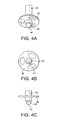
- FIGS. 4a, 4b and 4c show an alternative one way vent valve that can be implemented in the embodiments of present invention.
- the hemispherical valve 40 comprises a hemispherical shaped membrane with a central slit 41 which allows the passage of air therethrough. Any suitable cut such as a cross is also possible. The slit or cut is dimensioned to allow low pressure air venting as well as high temperature sealing.
- the hemispherical valve of Figures 4a to 4c could also be used for other applications.
- it could be located on the apex of the teat to allow the passage of fluid therethrough or on the flange of the teat to allow passage of air therethrough.
- valve 34 or 40 The dimension, material and construction of the valve 34 or 40 is of particular significance in obtaining a natural feeding action for the bottle.
- Most valving systems currently known allow a teat to vent at approximately 5000 Pa (pascal) by virtue of the closing force determined by the resilience of the valve walls surrounding the slit, for example because of their stiffness.
- the infant in use, the infant must exert an unnaturally high sucking force before venting can take place which can give rise to problems and results in sucking action more powerful than that required in natural feeding.
- a high resilient closing force is required to ensure that the valve does not leak milk into the vent tube, for example when the infant exerts squeezing pressure on the teat.
- the valve 34 or 40 is constructed such that a negative pressure in the region of 100 to 2500 Pa, more preferably 500 to 1500 Pa and most preferably 1000 Pa will be sufficient to open the valve to allow venting when the infant sucks on the bottle, requiring significantly less suction by the infant and a more natural feeding action.
- a negative pressure in the region of 100 to 2500 Pa, more preferably 500 to 1500 Pa and most preferably 1000 Pa will be sufficient to open the valve to allow venting when the infant sucks on the bottle, requiring significantly less suction by the infant and a more natural feeding action.
- a negative pressure in the region of 100 to 2500 Pa, more preferably 500 to 1500 Pa and most preferably 1000 Pa will be sufficient to open the valve to allow venting when the infant sucks on the bottle, requiring significantly less suction by the infant and a more natural feeding action.
- the recognition, according to the invention that it is only necessary to prevent leakage of milk into the valve and vent tube when the bottle is in the upright position (and hence the valve is immersed in
- the invention recognises that a less significant resilient closing force is required for the valve because of the additional force applied to the sides of the valve when the bottle is standing upright as a result of the head of pressure exerted by the milk in the bottle.
- This force provides the additional closing force sufficient to prevent leakage into the valve and vent tube. Accordingly when the infant is drinking from the bottle in its inverted position, because the valve has a smaller resilient closing force it opens under a lower negative pressure as a result of which a more natural feeding action is represented.
- an appropriate duck-billed valve or hemispherical valve to meet the criteria set out above using routine trial and experimentation, for example by varying the wall or membrane thickness and hence stiffness of valves and applying an appropriate negative pressure to obtain venting at the desired pressure and/or by immersing the valves in liquids of a similar density to that of milk or other fluids used by the infant with an appropriate head of pressure, for example 5 to 10 cm.
- the valve is fabricated so that it remains closed even with a low head of pressure, for example 5mm.
- the valve is formed of pure silicone rubber with typical 30 to 60 Shore A hardness as available from any silicone supplier such as GE, Bayer, Dow, Wacker, Rhone Poulenc. Both liquid silicone and compression moulding silicone grades are suitable for the present invention as they provide high heat stability, important for repeated heat sterilising methods. Other grades may also be suitable.
- the valve walls having a valve thickness 0.5 mm. Viewed from the front the duck-billed valve forms the shape of an inverted triangle of height 10.0mm and base 8.0mm. Viewed from the side the duck-billed valve is generally rectangular in cross-section having a width of 7.0 mm. A slit is formed on the exit end of the valve by a cut with a length of 2.5mm to 4 mm. It is found that this configuration provides the desired operating range and in particular an ability to open up under a negative pressure of just 1000 Pa.
- the hemispherical valve is formed of pure silicone rubber with typical 30 to 60 Shore A hardness as available from any silicone supplier such as GE, Bayer, Dow, Wacker, Rhone Poulenc. Both liquid silicone and compression moulding silicone grades are suitable for the present invention as they provide high heat stability, important for repeated heat sterilising methods. Other grades may also be suitable.
- the key dimensions of the hemispherical valve 40 for high temperature sealing are its radius, wall thickness, length of central slit 41 and material softness.
- the hemispherical valve has a radius of 2mm to 5mm, most preferably 3.5mm, and a wall thickness of 0.3mm to 0.7 mm, most preferably 0.5 mm.
- the central slit dimension is in the region of 2.5mm to 4.0 mm. It is found that this configuration provides low level suction but is also inherently strong enough to withstand pressures associated with liquid up to boiling point temperature without leakage.
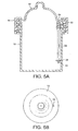
- FIGs. 5a and 5b show a second embodiment of the present invention in which there is an alternative air entry system.
- An air passage is formed by an air inlet aperture 51 on the flange of the teat 12 and an air conduit member 50 projecting downwardly of the teat.
- the air conduit member 50 provides communication between atmosphere and a vent tube 22 which is attached to the air conduit member with an airtight push fit.
- the air conduit member 50 can be integrally formed on the flange of the teat 12, for example in the form of a stalk projecting downwardly of the teat at the teat aperture 51.
- the teat 12 is mounted by screw collar 14 onto container 16.
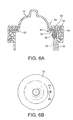
- the air conduit member 56 is integrally formed on a support member, for example in the form of a sealing ring 52.
- the air conduit member 56 projects downwards of the sealing ring 52.
- the sealing ring 52 is of similar diameter to container 16 and arranged to fit on the lip of the container to be gripped in a liquid tight condition by the flange of teat 12 pressed down by collar 14.
- the sealing ring 52 additionally provides support for the flange of the teat 12.
- a recess 55 is formed on the flange of the teat 12 which leads to an air inlet aperture 53 in the teat.
- An air passage is formed between the flange recess 55 and the screw collar 14 which allows for the passage of air from atmosphere through the aperture 53 on the flange of the teat, which is suitably aligned above the conduit member 56 on the ring 52, and air conduit member 56 to the vent tube 22, as shown by dotted arrow 54.
- the vent tube 22 is attached to the air conduit member 56 with an airtight push fit.
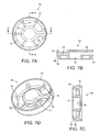
- Figs. 7a to 7d show an alternative feeding bottle insert head portion 70.
- the head portion includes hub 71 connected to a rim 72 by spokes 73.
- a liquid conduit is formed by spaces 74 between the hub 71, rim 72 and spokes 73.
- the liquid conduit provides communication between the container 16 and the teat 12 (neither shown) such that when the feeding bottle is inverted liquid passes from the container through the spaces 74 and into the teat allowing an infant to feed.
- At least one of the spokes 75 is of sufficient thickness to allow a generally radial bore to be formed therethrough providing an air passage 76 to an open ended chamber 77.
- the air passage 76 communicates the vent tube 22 (not shown), which is attached to an open ended chamber 77 by push fit and projects downwardly of the head portion 70, to the atmosphere via the screw threads of the collar 14 (not shown).
- An annular recess 78 in the underside of the generally annular shaped rim 72 provides a liquid tight seal between the head portion and the container 12 (not shown).
- the recess 78 is formed such that an inner surface 79 fits inside the container and an upper surface 80 rests on the lip of the container.
- the vent tube 22 is preferably made of generally rigid, inert material such as plastics material and the valve 34 or 40 can be made of silicone rubber or other appropriate material for the purposes required.
- the flange 36 is preferably made of rigid plastic material allowing mixing and an anti-choke function and can be two-shot moulded with the valve 34 or 40 if appropriate.
- various elements are connected by push fit allowing easy disassembly and cleaning but any appropriate manner of connection can be adopted and indeed where appropriate the various parts can be formed integrally or non-detachably.
- the head portion 20 is preferably of a semi-rigid material ensuring that the air passage 26 is not closed by deformation of the flange portion 28 but at the same time a reliable liquid tight seal is provided at the neck of the container.
- the support member of the third embodiment is preferably of a semi-rigid material ensuring that the air conduit member 56 is not closed by deformation when push fitted to the vent tube 22 but at the same time a reliable liquid tight seal is provided at the neck of the container 16.
- the neck insert 18 can be integral with the container/collar or can be detachable as appropriate for cleaning purposes.
- the neck insert 18 can provide a simple modular attachment to a standard feeding bottle and in many cases the existing collar can be used in cooperation with the neck insert 18.
- the neck insert 18 can be provided with a specially tailored collar of appropriate depth to ensure good screw-thread engagement.
- the valve allows natural feeding by venting at very low pressure. Because the vent tube 22 is valved at its base, pressure equalisation is provided within the container without allowing the infant to deform the teat and push liquid away from the teat. Also, because the valve provides a liquid seal there is no risk of leakage of liquid through the neck insert and down the side of the container. A simple and modular arrangement is provided for the neck insert. By virtue of the addition of a valve flange mixing and stirring can be improved whilst choke hazards can be avoided.
- valve any appropriate type of valve can be used in place of the duck-billed valve or hemispherical valve described above.
- the dimensions of the container and the various components can be varied as appropriate and the specific positioning of the various elements can be rearranged as appropriate.
- any other appropriate shape and positioning of the valve flange can be adopted.
Claims (13)
- Biberon (10) comprenant un récipient (16), une partie formant bride (28) agencée au niveau d'une extrémité d'entrée d'air du biberon (10) et un conduit d'air (22) s'étendant à partir de ladite bride (28) dans le récipient (16) dans une direction sensiblement perpendiculaire au plan de ladite bride (28) et sensiblement vers une extrémité du biberon distale par rapport à l'extrémité d'entrée d'air, le conduit (22) ayant une soupape d'évent (34) au niveau de son extrémité distale, la soupape d'évent (34) étant configurée pour se fermer suite à la pression d'une tête de liquide dans le récipient (16) et pour s'ouvrir sous une pression négative appliquée au récipient (16) dans la plage de 100 Pa à 2 500 Pa, dans lequel la soupape d'évent (34) est une soupape à une seule voie et le conduit d'air (22) inclut en outre une bride (36) comprenant une partie anti-étouffement (36) s'étendant latéralement par rapport au conduit d'air (22) au niveau de l'extrémité distale.
- Biberon (10) selon la revendication 1, dans lequel la soupape d'évent (34) est configurée pour s'ouvrir à une pression négative dans la plage de 500 Pa à 1 500 Pa.
- Biberon (10) selon la revendication 2, dans lequel la soupape d'évent (34) est configurée pour s'ouvrir à une pression négative de 1 000 Pa.
- Biberon (10) selon n'importe laquelle des revendications 1 à 3, dans lequel la soupape d'évent (34) comprend une soupape en bec de canard, ou dans lequel la soupape d'évent (34) comprend une soupape hémisphérique.
- Biberon (10) selon la revendication 1, dans lequel la partie anti-étouffement (36) est attachée à la soupape à une seule voie (34), et de préférence dans lequel la partie anti-étouffement (36) et la soupape (34) sont formées d'un seul tenant et attachées de façon amovible au conduit d'air (22).
- Biberon (10) selon la revendication 1, incluant en outre une partie d'étanchéité (20) pouvant être scellé contre une ouverture du conteneur, la partie d'étanchéité (20) incluant un passage de liquide entre le récipient et une embouchure, et de préférence dans lequel la partie d'étanchéité inclut en outre un passage d'évent fournissant un passage d'air jusqu'au conduit d'air.
- Biberon (10) selon la revendication 1, comprenant en outre un trayon (12) ayant un élément formant conduit d'air (50) définissant un passage d'air jusqu'au conduit d'air, ou comprenant en outre un élément de support (52) ayant un élément formant conduit d'air (56) définissant un passage d'air jusqu'au conduit d'air.
- Ensemble formant évent de biberon (18) comprenant une partie d'étanchéité (20) ayant séparément un passage de liquide et un passage d'évent, la partie d'étanchéité (20) incluant en outre une partie formant bride (28) et un conduit d'air (22) s'étendant à partir de ladite bride (28) dans une direction sensiblement perpendiculaire au plan de la bride (28), le conduit d'air (22) communiquant avec le passage d'évent (26) et une soupape à une seule voie (34) montée sur le conduit d'air (22) au niveau de son extrémité distale, le conduit d'air (22) incluant en outre une bride (36) comprenant une partie anti-étouffement (36) s'étendant latéralement à partir du conduit d'air (22) au niveau de l'extrémité distale, dans lequel une soupape à une seule voie (34) est configurée pour se fermer suite à la pression d'une tête du liquide appliquée à la soupape (34) et pour s'ouvrir à une position de décharge lors de l'application d'une pression négative entre 100 Pa et 2 500 Pa, dans lequel, lorsque l'ensemble formant évent de biberon est installé dans un biberon, le conduit d'air (22) s'étend sensiblement vers une extrémité du biberon distale par rapport à une extrémité d'entrée d'air.
- Biberon (10) incluant un ensemble formant évent (18) comme revendiqué dans la revendication 8.
- Ensemble formant soupape de biberon (18) comme revendiqué dans la revendication 8, dans lequel la partie anti-étouffement (36) est attachée à la soupape à une seule voie (34).
- Biberon (10) comme revendiqué dans la revendication 1, dans lequel ladite soupape d'évent (34) est une soupape hémisphérique comprenant un élément hémisphérique d'épaisseur de paroi de 0,3 mm à 0,7 mm, le plus de préférence 0,5 mm, avec un rayon de 2 mm à 5 mm, le plus de préférence 3,5 mm, et une fente de dimension 2,5 mm à 4,0 mm pour le passage de fluide à travers celle-ci, et de préférence dans lequel l'élément hémisphérique est fait d'une matière avec une dureté Shore A de 30 à 60.
- Biberon (10) comme revendiqué dans la revendication 11, comprenant en outre un trayon (12), dans lequel le trayon (12) comprend la soupape hémisphérique.
- Biberon (10) comme revendiqué dans la revendication 12, dans lequel la soupape hémisphérique est située sur l'apex du trayon (12) pour permettre le passage de fluide à travers ce dernier, ou dans lequel la soupape hémisphérique est située sur une partie formant bride du trayon (12) pour permettre le passage d'air à travers ce dernier.
Priority Applications (1)
| Application Number | Priority Date | Filing Date | Title |
|---|---|---|---|
| PL05744834T PL1755524T3 (pl) | 2004-05-17 | 2005-05-17 | Butelka do karmienia |
Applications Claiming Priority (2)
| Application Number | Priority Date | Filing Date | Title |
|---|---|---|---|
| GBGB0410993.0A GB0410993D0 (en) | 2004-05-17 | 2004-05-17 | Feeding bottle |
| PCT/GB2005/001883 WO2005112869A1 (fr) | 2004-05-17 | 2005-05-17 | Biberon |
Publications (2)
| Publication Number | Publication Date |
|---|---|
| EP1755524A1 EP1755524A1 (fr) | 2007-02-28 |
| EP1755524B1 true EP1755524B1 (fr) | 2015-09-02 |
Family
ID=32607462
Family Applications (1)
| Application Number | Title | Priority Date | Filing Date |
|---|---|---|---|
| EP05744834.2A Active EP1755524B1 (fr) | 2004-05-17 | 2005-05-17 | Biberon |
Country Status (13)
| Country | Link |
|---|---|
| US (1) | US7798347B2 (fr) |
| EP (1) | EP1755524B1 (fr) |
| JP (2) | JP4847757B2 (fr) |
| KR (1) | KR101273968B1 (fr) |
| CN (1) | CN1972660B (fr) |
| AU (1) | AU2005244643B2 (fr) |
| CA (1) | CA2565507C (fr) |
| ES (1) | ES2552032T3 (fr) |
| GB (1) | GB0410993D0 (fr) |
| NZ (1) | NZ551239A (fr) |
| PL (1) | PL1755524T3 (fr) |
| TW (1) | TWI337862B (fr) |
| WO (1) | WO2005112869A1 (fr) |
Families Citing this family (46)
| Publication number | Priority date | Publication date | Assignee | Title |
|---|---|---|---|---|
| US8113365B2 (en) * | 2000-05-08 | 2012-02-14 | New Vent Designs Inc. | Fully vented nursing bottle with single piece vent tube |
| US20110233236A1 (en) * | 2010-03-25 | 2011-09-29 | Brown Craig E | Continuous, complete, automatic, non-leaking, non-aerating, positive pressure one-piece vent and pouring combination utilizing one direct venting aperture |
| KR100954853B1 (ko) * | 2008-03-04 | 2010-04-28 | 박용직 | 환경호르몬 방지 젖병 |
| WO2009010620A1 (fr) * | 2007-07-17 | 2009-01-22 | Ferri Garcia Marcelino | Biberon amélioré |
| ES2343230B1 (es) * | 2007-07-17 | 2011-04-28 | Marcelino Ferri Garcia | Dispositivo roscado con valvula de aire para perfeccionar recipientestipo biberon convencional. |
| US8863969B2 (en) * | 2007-09-04 | 2014-10-21 | Chantal Lau | Feeding bottle system |
| US10137059B2 (en) * | 2008-01-29 | 2018-11-27 | Craig E Brown | Nursing bottle with integrated collar and nipple flange venting structure |
| US10138034B2 (en) * | 2008-01-29 | 2018-11-27 | Craig E Brown | Singular cap compound vented nursing and related bottle |
| DE102008027606A1 (de) * | 2008-06-10 | 2009-12-17 | Novatex Gesellschaft mit beschränkter Haftung Gummi- und Plastikwaren | Belüftungsvorrichtung für eine Trinkflasche |
| JP5395898B2 (ja) * | 2008-06-12 | 2014-01-22 | メデラ ホールディング アーゲー | 乳首部 |
| GB0811050D0 (en) * | 2008-06-17 | 2008-07-23 | U Pol Ltd | A Connector for a gravity feed spray gun, a gravity feed spray gun and a method of preparing a spray paint |
| US7984818B1 (en) * | 2008-06-30 | 2011-07-26 | Dominick Joseph Fucito | Vented nursing bottle with leak prevention means |
| CN101332154B (zh) * | 2008-07-11 | 2013-06-12 | 东莞市银燕塑料容器有限公司 | 一种回气奶瓶 |
| CN201346316Y (zh) * | 2009-01-19 | 2009-11-18 | 广州健士婴童用品有限公司 | 奶瓶回气系统 |
| US20100308003A1 (en) * | 2009-06-04 | 2010-12-09 | Adiri, Inc. | Modular and Natural Infant Feeding Container |
| CH701676A1 (de) * | 2009-08-20 | 2011-02-28 | Medela Holding Ag | Saugnippeleinheit. |
| US20110100945A1 (en) * | 2009-09-24 | 2011-05-05 | Henry Alfonso Gutierrez | Vent system for a dispensing unit |
| USD644334S1 (en) | 2010-03-11 | 2011-08-30 | Medical Instill Technologies, Inc. | Bottle with nipple |
| US20160046421A1 (en) * | 2010-03-25 | 2016-02-18 | Craig E. Brown | Sectionalized fluids container |
| US20120192977A1 (en) * | 2011-01-27 | 2012-08-02 | Tsao Yu-Yao | Duck-billed check valve |
| US8967405B2 (en) | 2011-08-31 | 2015-03-03 | Light Bulb Inventions, Llc | Venting baby bottle |
| US10100402B2 (en) | 2011-10-07 | 2018-10-16 | International Business Machines Corporation | Substrate holder for graphene film synthesis |
| USD720464S1 (en) | 2012-08-22 | 2014-12-30 | Tomy International, Inc. | Baby bottle |
| BR112015015967A2 (pt) * | 2013-01-10 | 2017-07-11 | Handi Craft Co | conjunto de garrafa de configuração dual |
| CN103405344B (zh) * | 2013-05-24 | 2015-09-23 | 孙庆扬 | 一种具有回气功能的奶瓶 |
| US10166172B2 (en) * | 2013-07-10 | 2019-01-01 | Handi-Craft Company | Dual configuration bottle assembly |
| ES2878176T3 (es) * | 2014-02-16 | 2021-11-18 | T T Y General Trade Lines Ltd | Recipiente de líquido ventilado |
| US20190210775A1 (en) * | 2014-06-24 | 2019-07-11 | Craig E. Brown | Universal Single Piece Venting Insert For Container |
| USD865191S1 (en) | 2016-08-03 | 2019-10-29 | Craig E Brown | Vented nursing bottle nipple |
| US9907731B2 (en) | 2014-11-20 | 2018-03-06 | Chantal Lau | Self-paced ergonomic infant feeding bottle |
| US10085920B2 (en) * | 2015-03-09 | 2018-10-02 | Benir Baby, LTd | Vented baby bottle |
| FR3035321B1 (fr) * | 2015-04-24 | 2021-04-02 | Cva Tech Pure Silicone Group Ag | Dispositif d'allaitement et biberon associe |
| US10195117B2 (en) | 2015-06-03 | 2019-02-05 | James J. Britto | Vented bottle |
| US11596580B2 (en) * | 2016-03-03 | 2023-03-07 | Qingyang SUN | Nursing bottle having air returning function |
| AU2017252600A1 (en) * | 2016-04-21 | 2018-10-11 | Mayborn (Uk) Limited | Bottle assembly and valve assembly |
| CN106860025B (zh) * | 2017-03-06 | 2024-02-06 | 浙江帅宝塑胶制品有限公司 | 一种奶瓶 |
| CN111818897B (zh) * | 2018-03-02 | 2023-05-23 | 汉迪-克拉夫特公司 | 瓶组件 |
| EP3598964B1 (fr) * | 2018-07-23 | 2021-06-09 | Koninklijke Philips N.V. | Composant de séparation pour un dispositif formant biberon et dispositif formant biberon |
| USD935630S1 (en) * | 2018-11-01 | 2021-11-09 | Thermos L.L.C. | Sleeve for a baby bottle |
| EP3677239A1 (fr) * | 2019-01-02 | 2020-07-08 | Koninklijke Philips N.V. | Dispositif formant biberon |
| CN109621041A (zh) * | 2019-01-23 | 2019-04-16 | 滨海昌正企业管理有限公司 | 一种隐藏在吸奶器主机内部的集奶装置 |
| CA186685S (en) * | 2019-03-04 | 2020-02-21 | Upis Co Ltd | Feeding bottle |
| USD919822S1 (en) * | 2019-04-22 | 2021-05-18 | Rengao Wang | Feeding bottle |
| NL2023437B1 (en) * | 2019-07-04 | 2021-02-02 | Dethapak Innovation B V | Pour spout for facilitating pouring a liquid from a container |
| EP3878427A1 (fr) * | 2020-03-13 | 2021-09-15 | Koninklijke Philips N.V. | Composant de partitionnement pour un biberon |
| GB202204192D0 (en) * | 2022-03-24 | 2022-05-11 | Mayborn Uk Ltd | Venting member, feeding bottle, and method of forming a venting member |
Family Cites Families (95)
| Publication number | Priority date | Publication date | Assignee | Title |
|---|---|---|---|---|
| US71570A (en) * | 1867-12-03 | Mikel beck | ||
| US380835A (en) * | 1888-04-10 | Waltee f | ||
| GB191204210A (en) | 1912-02-20 | 1912-06-13 | Arnold Prox | Improvements in Rubber Teats for Feeding Bottles. |
| US3207349A (en) | 1963-12-18 | 1965-09-21 | George B Rabe | Nursing bottle |
| US3704803A (en) | 1971-07-13 | 1972-12-05 | Charles L Ponder | Nursing bottle |
| GB1453968A (en) | 1972-12-07 | 1976-10-27 | Tonkin S L | Artificial baby feeding |
| FI831194L (fi) | 1983-04-08 | 1984-10-09 | Byong Wha Suh | Nappflaska. |
| GB2154451B (en) | 1984-02-01 | 1988-04-27 | Avent Medical Ltd | Improvements in baby feed bottles |
| GB2167735A (en) | 1984-11-21 | 1986-06-04 | Khung Ngee Tan | Teat |
| DE3530911A1 (de) | 1985-08-29 | 1987-03-12 | Helvoet Pharma | Orthodontischer flaschensauger |
| JP2741868B2 (ja) | 1988-06-13 | 1998-04-22 | ピジョン株式会社 | 哺乳瓶用キャップ付乳首 |
| JP2622598B2 (ja) | 1988-11-28 | 1997-06-18 | ピジョン株式会社 | 哺乳器用乳首 |
| JPH02161950A (ja) | 1988-12-15 | 1990-06-21 | Jiekusu Kk | 乳首 |
| GB9023707D0 (en) * | 1990-10-31 | 1990-12-12 | Sepehr Fereidoon | Baby bottle with an automatic air inlet valve |
| JPH0584279A (ja) | 1991-09-30 | 1993-04-06 | Pigeon Corp | 哺乳器用乳首 |
| JPH05115535A (ja) | 1991-10-30 | 1993-05-14 | Pigeon Corp | 哺乳器用乳首 |
| CA2162247C (fr) * | 1993-05-18 | 2001-02-13 | Nady Bilani | Contenant pour liquides |
| US5474028A (en) | 1994-01-25 | 1995-12-12 | Merrick's, Inc. | Animal feeding nipple |
| USD486579S1 (en) | 1994-11-03 | 2004-02-10 | Munchkin, Inc. | Baby bottle nipple |
| US5544766A (en) | 1994-11-04 | 1996-08-13 | Munchkin Bottling Inc. | Coded two part nipple members for baby bottles and method of making |
| FR2732590B1 (fr) | 1995-04-10 | 1997-06-20 | Busnel Marie Claire | Tetine pour biberon, ainsi qu'un biberon equipe d'une telle tetine |
| US5678710A (en) | 1995-07-12 | 1997-10-21 | Sheu; Miin-Tsang | Nipple for nursing bottles |
| US5779071A (en) | 1995-08-04 | 1998-07-14 | New Vent Designs, Inc. | Nursing bottle with an air venting structure |
| US5570796A (en) | 1995-08-04 | 1996-11-05 | Brown; Craig E. | Nursing bottle with an air venting structure |
| USD384748S (en) | 1995-11-09 | 1997-10-07 | Munchkin, Inc. | Baby bottle nipple |
| GB9523215D0 (en) * | 1995-11-13 | 1996-01-17 | Petro Man Ltd | Filling of tanks with volatile liquids |
| DE19716534A1 (de) | 1996-04-23 | 1997-11-06 | Heike Rummel | Sauger für Trinkgefäße für Säuglinge und Kleinkinder |
| AU5196398A (en) | 1996-12-11 | 1998-07-03 | Playtex Products, Inc. | Leakproof nipple valve |
| US5881893A (en) | 1996-12-21 | 1999-03-16 | Playtex Products, Inc. | Leakproof nipple valve |
| USD412582S (en) | 1997-04-14 | 1999-08-03 | Playtex Products, Inc. | Combined nipple and ring |
| USD404138S (en) | 1997-07-17 | 1999-01-12 | Gerber Products Company | Combined nipple and collar |
| US6032810A (en) | 1997-07-17 | 2000-03-07 | Gerber Products Company | One-piece nipple/collar for nursers and the like |
| US6161710A (en) | 1997-11-03 | 2000-12-19 | Dieringer; Mary F. | Natural nipple baby feeding apparatus |
| USD405530S (en) | 1997-11-04 | 1999-02-09 | Playtex Products, Inc. | Rounded tip nipple |
| USD454642S1 (en) | 1997-11-21 | 2002-03-19 | Nouri E. Hakim | Baby bottle |
| GB9802095D0 (en) * | 1998-01-30 | 1998-03-25 | Cannon Rubber Ltd | Closure assembly |
| JP4049451B2 (ja) | 1998-06-16 | 2008-02-20 | ピジョン株式会社 | 飲料容器 |
| US6112919A (en) | 1998-07-13 | 2000-09-05 | Ho; Shu-E | Leakage preventive device for milk bottles or the like |
| US20050288712A9 (en) | 1998-08-21 | 2005-12-29 | Hakim Nouri E | Pacifier and baby bottle nipple systems |
| US6241110B1 (en) | 1998-08-21 | 2001-06-05 | Nouri E. Hakim | Baby products and methods of manufacture |
| US20020030029A1 (en) | 1998-08-21 | 2002-03-14 | Hakim Nouri E. | Pacifier shields |
| USD421306S (en) | 1998-10-13 | 2000-02-29 | Gerber Products Company | Combined nipple and collar |
| JP2000189496A (ja) | 1998-10-20 | 2000-07-11 | Pigeon Corp | 人工乳首 |
| DE19849271A1 (de) * | 1998-10-26 | 2000-04-27 | Herbert Willmann | Vorrichtung für eine zum Saugen eingerichtete Trinkflasche |
| US6068147A (en) * | 1998-11-24 | 2000-05-30 | Sheu; Miin-Shiou | Air intake aiding plate for nipples of feeding bottles |
| US7122045B2 (en) | 2001-11-13 | 2006-10-17 | Playtex Products, Inc. | Nipple |
| US6645228B2 (en) | 2001-11-13 | 2003-11-11 | Playtex Products, Inc. | Nipple |
| US7326234B2 (en) | 1998-12-10 | 2008-02-05 | Playtex Products, Inc. | Vented bottle |
| EP1161219B8 (fr) | 1999-03-17 | 2009-09-09 | Morrill, Jennifer | Recipient destine a nourrir un nourrisson |
| JP3209271B2 (ja) | 1999-03-29 | 2001-09-17 | ジェクス株式会社 | 哺乳びん用乳首 |
| USD441870S1 (en) | 1999-10-20 | 2001-05-08 | Playtex Products, Inc. | Nipple |
| GB0004210D0 (en) | 2000-02-23 | 2000-04-12 | Mead Corp | Carton and carton blanks |
| USD444239S1 (en) | 1999-11-12 | 2001-06-26 | Jex Co., Ltd. | Nipple |
| US20020063103A1 (en) | 1999-12-13 | 2002-05-30 | Kathleen Kiernan | Nipple for nursing bottle |
| JP3380201B2 (ja) | 1999-12-16 | 2003-02-24 | ピジョン株式会社 | 人工乳首 |
| JP3405304B2 (ja) | 1999-12-28 | 2003-05-12 | ジェクス株式会社 | おしゃぶり |
| JP4233074B2 (ja) | 2000-04-24 | 2009-03-04 | ピジョン株式会社 | 人工乳首 |
| JP2002011076A (ja) | 2000-04-24 | 2002-01-15 | Pigeon Corp | 人工乳首 |
| JP4233075B2 (ja) | 2000-04-27 | 2009-03-04 | ピジョン株式会社 | 人工乳首 |
| CN2428128Y (zh) * | 2000-06-27 | 2001-05-02 | 邓立新 | 一种带单向进气阀的奶瓶 |
| JP2002200144A (ja) | 2000-12-28 | 2002-07-16 | Pigeon Corp | 人工乳首用固定具、人工乳首付き固定具及び哺乳器 |
| JP2002306572A (ja) | 2001-04-11 | 2002-10-22 | Pigeon Corp | 哺乳器用乳首およびその製造方法 |
| USD463567S1 (en) | 2001-08-20 | 2002-09-24 | Munchkin, Inc. | Nipple |
| USD464434S1 (en) | 2001-08-20 | 2002-10-15 | Munchkin, Inc. | Bottle with nipple |
| US6499615B1 (en) * | 2001-09-11 | 2002-12-31 | William K. Szieff | Angled cap and vent for use with a baby bottle |
| GB2380186A (en) | 2001-09-28 | 2003-04-02 | Cannon Rubber Ltd | Thick feed baby teat |
| USD465028S1 (en) | 2001-10-29 | 2002-10-29 | Playtex Products, Inc. | Nipple |
| USD488560S1 (en) | 2001-10-29 | 2004-04-13 | Playtex Products, Inc. | Nipple |
| JP3992477B2 (ja) | 2001-11-09 | 2007-10-17 | ピジョン株式会社 | 人工乳首および哺乳器 |
| JP4289592B2 (ja) | 2001-11-09 | 2009-07-01 | ピジョン株式会社 | 人工乳首及び哺乳器 |
| USD459815S1 (en) | 2001-11-20 | 2002-07-02 | Edward J. Pastucha | Combined baby bottle nipple and bottle cap for fitting on water bottles |
| US20030106872A1 (en) | 2001-12-10 | 2003-06-12 | Hung-Hsiu-Hua Lin | Nipple with air intake valve |
| USD520142S1 (en) | 2002-03-15 | 2006-05-02 | Baby Innovations Marketing E | Teat |
| EP1501464A1 (fr) | 2002-05-03 | 2005-02-02 | Munchkin, Inc. | Ensemble biberon a ecoulement variable |
| DE20210121U1 (de) * | 2002-06-29 | 2002-10-02 | Sheu Miin Tsang | Milchflaschen-Sauger mit Verlängerungsrohr zum Schutz gegen Magenaufblähung |
| PA8578901A1 (es) | 2002-08-05 | 2004-04-23 | Nouri E Hakim | "productos para beber sin derrames" "no-spill drinking products" |
| JP3916543B2 (ja) | 2002-10-11 | 2007-05-16 | ピジョン株式会社 | 哺乳器 |
| USD479606S1 (en) | 2002-10-15 | 2003-09-09 | Playtex Products, Inc. | Nipple |
| USD504723S1 (en) | 2002-10-15 | 2005-05-03 | Playtex Products, Inc. | Nipple |
| US7150370B2 (en) * | 2002-10-21 | 2006-12-19 | Sung-Hwan Pyun | Air venting apparatus for milk bottle |
| AT413978B (de) | 2003-01-20 | 2006-07-15 | Bamed Ag | Luftventil für einen deckel eines trinkbehälters |
| AT413979B (de) | 2003-01-20 | 2006-07-15 | Bamed Ag | Trink-mundstück |
| US20040188373A1 (en) | 2003-03-25 | 2004-09-30 | Lewis Julie Maureen | Vented, low-drip nursing bottle |
| AT6721U1 (de) | 2003-04-29 | 2004-03-25 | Bamed Ag | Sauger |
| US6984688B2 (en) | 2003-05-02 | 2006-01-10 | Gls Corp | Injection-moldable transparent thermoplastic elastomer |
| US20040226906A1 (en) | 2003-05-12 | 2004-11-18 | Johan Peterson | Baby bottle nipple |
| US20040256345A1 (en) | 2003-06-20 | 2004-12-23 | Lundquist Jon Tyler | Single use recyclable infant feeding bottle |
| GB2412114B (en) | 2004-03-19 | 2007-03-14 | Ilan Zadik Samson | Vented teat |
| JP4035574B2 (ja) | 2004-04-07 | 2008-01-23 | 株式会社パタカラ | 哺乳瓶用の吸口 |
| US20050252875A1 (en) | 2004-05-14 | 2005-11-17 | Miin-Tsang Sheu | Air inlet valve of a nipple used for a bottle |
| JP4813777B2 (ja) | 2004-06-29 | 2011-11-09 | ピジョン株式会社 | 人工乳首及び哺乳器 |
| US20070045214A1 (en) | 2004-07-27 | 2007-03-01 | Jennings James E | Nipple spout |
| US7857153B2 (en) | 2004-07-29 | 2010-12-28 | Pigeon Corporation | Artificial nipple, infant feeding device, and artificial nipple manufacturing method |
| JP4907069B2 (ja) | 2004-09-03 | 2012-03-28 | ピジョン株式会社 | 人工乳首及び哺乳器 |
| US20060213859A1 (en) * | 2005-03-25 | 2006-09-28 | Miin-Tsang Sheu | Flatulence-resisting nursing bottle air cap |
-
2004
- 2004-05-17 GB GBGB0410993.0A patent/GB0410993D0/en not_active Ceased
- 2004-08-19 TW TW093124917A patent/TWI337862B/zh not_active IP Right Cessation
-
2005
- 2005-05-17 US US11/596,546 patent/US7798347B2/en active Active
- 2005-05-17 AU AU2005244643A patent/AU2005244643B2/en active Active
- 2005-05-17 EP EP05744834.2A patent/EP1755524B1/fr active Active
- 2005-05-17 PL PL05744834T patent/PL1755524T3/pl unknown
- 2005-05-17 ES ES05744834.2T patent/ES2552032T3/es active Active
- 2005-05-17 NZ NZ551239A patent/NZ551239A/en not_active IP Right Cessation
- 2005-05-17 JP JP2005517156A patent/JP4847757B2/ja not_active Expired - Fee Related
- 2005-05-17 CN CN2005800160029A patent/CN1972660B/zh active Active
- 2005-05-17 CA CA2565507A patent/CA2565507C/fr not_active Expired - Fee Related
- 2005-05-17 KR KR1020067026585A patent/KR101273968B1/ko not_active IP Right Cessation
- 2005-05-17 WO PCT/GB2005/001883 patent/WO2005112869A1/fr active Application Filing
-
2009
- 2009-08-21 JP JP2009191709A patent/JP2009273912A/ja active Pending
Also Published As
| Publication number | Publication date |
|---|---|
| PL1755524T3 (pl) | 2016-02-29 |
| JP4847757B2 (ja) | 2011-12-28 |
| US20080099422A1 (en) | 2008-05-01 |
| NZ551239A (en) | 2011-01-28 |
| TW200538094A (en) | 2005-12-01 |
| WO2005112869A1 (fr) | 2005-12-01 |
| TWI337862B (en) | 2011-03-01 |
| AU2005244643A1 (en) | 2005-12-01 |
| EP1755524A1 (fr) | 2007-02-28 |
| CA2565507C (fr) | 2014-07-08 |
| JP2009273912A (ja) | 2009-11-26 |
| KR20070027593A (ko) | 2007-03-09 |
| CN1972660A (zh) | 2007-05-30 |
| JP2007515976A (ja) | 2007-06-21 |
| CN1972660B (zh) | 2013-07-17 |
| ES2552032T3 (es) | 2015-11-25 |
| KR101273968B1 (ko) | 2013-06-12 |
| GB0410993D0 (en) | 2004-06-23 |
| US7798347B2 (en) | 2010-09-21 |
| AU2005244643B2 (en) | 2011-04-07 |
| CA2565507A1 (fr) | 2005-12-01 |
Similar Documents
| Publication | Publication Date | Title |
|---|---|---|
| EP1755524B1 (fr) | Biberon | |
| JP5041560B2 (ja) | 液漏れを防止する飲料容器用の蓋 | |
| US8777028B2 (en) | Spout for drinking container | |
| JP4991877B2 (ja) | 哺乳瓶のための通気弁アセンブリ | |
| US5779071A (en) | Nursing bottle with an air venting structure | |
| KR870001730B1 (ko) | 개량 젖병 | |
| US20070102388A1 (en) | Vented, low-drip nursing nipple | |
| KR20080045286A (ko) | 젖병 젖꼭지 | |
| AU2009200949A1 (en) | Closure assembly | |
| US20070045214A1 (en) | Nipple spout | |
| US10085920B2 (en) | Vented baby bottle | |
| US20140263157A1 (en) | Bottle closure and method | |
| US20180036207A1 (en) | Baby bottle nipple and configurations thereof | |
| EP1297814B1 (fr) | Tétine pour bébés pour nourriture épaisse | |
| WO2004002276A1 (fr) | Recipient a boire | |
| WO2014117209A1 (fr) | Capsule de récipient à boisson comportant une soupape à la demande | |
| CN215690001U (zh) | 奶嘴及容器 | |
| CN113277213A (zh) | 配备有吸管的奶瓶兼容盖子 | |
| MXPA98000521A (en) | Cubie drink cup | |
| MXPA98000913A (en) | Bibe |
Legal Events
| Date | Code | Title | Description |
|---|---|---|---|
| PUAI | Public reference made under article 153(3) epc to a published international application that has entered the european phase |
Free format text: ORIGINAL CODE: 0009012 |
|
| 17P | Request for examination filed |
Effective date: 20061218 |
|
| AK | Designated contracting states |
Kind code of ref document: A1 Designated state(s): AT BE BG CH CY CZ DE DK EE ES FI FR GB GR HU IE IS IT LI LT LU MC NL PL PT RO SE SI SK TR |
|
| DAX | Request for extension of the european patent (deleted) | ||
| 17Q | First examination report despatched |
Effective date: 20100204 |
|
| GRAP | Despatch of communication of intention to grant a patent |
Free format text: ORIGINAL CODE: EPIDOSNIGR1 |
|
| INTG | Intention to grant announced |
Effective date: 20150413 |
|
| GRAS | Grant fee paid |
Free format text: ORIGINAL CODE: EPIDOSNIGR3 |
|
| GRAA | (expected) grant |
Free format text: ORIGINAL CODE: 0009210 |
|
| AK | Designated contracting states |
Kind code of ref document: B1 Designated state(s): AT BE BG CH CY CZ DE DK EE ES FI FR GB GR HU IE IS IT LI LT LU MC NL PL PT RO SE SI SK TR |
|
| REG | Reference to a national code |
Ref country code: GB Ref legal event code: FG4D |
|
| REG | Reference to a national code |
Ref country code: AT Ref legal event code: REF Ref document number: 746082 Country of ref document: AT Kind code of ref document: T Effective date: 20150915 Ref country code: CH Ref legal event code: EP |
|
| REG | Reference to a national code |
Ref country code: IE Ref legal event code: FG4D |
|
| REG | Reference to a national code |
Ref country code: DE Ref legal event code: R096 Ref document number: 602005047394 Country of ref document: DE |
|
| REG | Reference to a national code |
Ref country code: ES Ref legal event code: FG2A Ref document number: 2552032 Country of ref document: ES Kind code of ref document: T3 Effective date: 20151125 |
|
| REG | Reference to a national code |
Ref country code: AT Ref legal event code: MK05 Ref document number: 746082 Country of ref document: AT Kind code of ref document: T Effective date: 20150902 |
|
| PG25 | Lapsed in a contracting state [announced via postgrant information from national office to epo] |
Ref country code: GR Free format text: LAPSE BECAUSE OF FAILURE TO SUBMIT A TRANSLATION OF THE DESCRIPTION OR TO PAY THE FEE WITHIN THE PRESCRIBED TIME-LIMIT Effective date: 20151203 Ref country code: LT Free format text: LAPSE BECAUSE OF FAILURE TO SUBMIT A TRANSLATION OF THE DESCRIPTION OR TO PAY THE FEE WITHIN THE PRESCRIBED TIME-LIMIT Effective date: 20150902 Ref country code: FI Free format text: LAPSE BECAUSE OF FAILURE TO SUBMIT A TRANSLATION OF THE DESCRIPTION OR TO PAY THE FEE WITHIN THE PRESCRIBED TIME-LIMIT Effective date: 20150902 |
|
| REG | Reference to a national code |
Ref country code: LT Ref legal event code: MG4D Ref country code: NL Ref legal event code: MP Effective date: 20150902 |
|
| PG25 | Lapsed in a contracting state [announced via postgrant information from national office to epo] |
Ref country code: SE Free format text: LAPSE BECAUSE OF FAILURE TO SUBMIT A TRANSLATION OF THE DESCRIPTION OR TO PAY THE FEE WITHIN THE PRESCRIBED TIME-LIMIT Effective date: 20150902 Ref country code: AT Free format text: LAPSE BECAUSE OF FAILURE TO SUBMIT A TRANSLATION OF THE DESCRIPTION OR TO PAY THE FEE WITHIN THE PRESCRIBED TIME-LIMIT Effective date: 20150902 |
|
| PG25 | Lapsed in a contracting state [announced via postgrant information from national office to epo] |
Ref country code: EE Free format text: LAPSE BECAUSE OF FAILURE TO SUBMIT A TRANSLATION OF THE DESCRIPTION OR TO PAY THE FEE WITHIN THE PRESCRIBED TIME-LIMIT Effective date: 20150902 Ref country code: IS Free format text: LAPSE BECAUSE OF FAILURE TO SUBMIT A TRANSLATION OF THE DESCRIPTION OR TO PAY THE FEE WITHIN THE PRESCRIBED TIME-LIMIT Effective date: 20160102 Ref country code: NL Free format text: LAPSE BECAUSE OF FAILURE TO SUBMIT A TRANSLATION OF THE DESCRIPTION OR TO PAY THE FEE WITHIN THE PRESCRIBED TIME-LIMIT Effective date: 20150902 Ref country code: SK Free format text: LAPSE BECAUSE OF FAILURE TO SUBMIT A TRANSLATION OF THE DESCRIPTION OR TO PAY THE FEE WITHIN THE PRESCRIBED TIME-LIMIT Effective date: 20150902 Ref country code: CZ Free format text: LAPSE BECAUSE OF FAILURE TO SUBMIT A TRANSLATION OF THE DESCRIPTION OR TO PAY THE FEE WITHIN THE PRESCRIBED TIME-LIMIT Effective date: 20150902 |
|
| REG | Reference to a national code |
Ref country code: FR Ref legal event code: PLFP Year of fee payment: 12 |
|
| REG | Reference to a national code |
Ref country code: DE Ref legal event code: R082 Ref document number: 602005047394 Country of ref document: DE Representative=s name: HERNANDEZ, YORCK, DIPL.-ING., DE |
|
| PG25 | Lapsed in a contracting state [announced via postgrant information from national office to epo] |
Ref country code: PT Free format text: LAPSE BECAUSE OF FAILURE TO SUBMIT A TRANSLATION OF THE DESCRIPTION OR TO PAY THE FEE WITHIN THE PRESCRIBED TIME-LIMIT Effective date: 20160104 Ref country code: RO Free format text: LAPSE BECAUSE OF FAILURE TO SUBMIT A TRANSLATION OF THE DESCRIPTION OR TO PAY THE FEE WITHIN THE PRESCRIBED TIME-LIMIT Effective date: 20150902 |
|
| REG | Reference to a national code |
Ref country code: DE Ref legal event code: R097 Ref document number: 602005047394 Country of ref document: DE |
|
| PLBE | No opposition filed within time limit |
Free format text: ORIGINAL CODE: 0009261 |
|
| STAA | Information on the status of an ep patent application or granted ep patent |
Free format text: STATUS: NO OPPOSITION FILED WITHIN TIME LIMIT |
|
| 26N | No opposition filed |
Effective date: 20160603 |
|
| PG25 | Lapsed in a contracting state [announced via postgrant information from national office to epo] |
Ref country code: DK Free format text: LAPSE BECAUSE OF FAILURE TO SUBMIT A TRANSLATION OF THE DESCRIPTION OR TO PAY THE FEE WITHIN THE PRESCRIBED TIME-LIMIT Effective date: 20150902 Ref country code: BE Free format text: LAPSE BECAUSE OF NON-PAYMENT OF DUE FEES Effective date: 20160531 Ref country code: SI Free format text: LAPSE BECAUSE OF FAILURE TO SUBMIT A TRANSLATION OF THE DESCRIPTION OR TO PAY THE FEE WITHIN THE PRESCRIBED TIME-LIMIT Effective date: 20150902 |
|
| PG25 | Lapsed in a contracting state [announced via postgrant information from national office to epo] |
Ref country code: BE Free format text: LAPSE BECAUSE OF FAILURE TO SUBMIT A TRANSLATION OF THE DESCRIPTION OR TO PAY THE FEE WITHIN THE PRESCRIBED TIME-LIMIT Effective date: 20150902 Ref country code: LU Free format text: LAPSE BECAUSE OF FAILURE TO SUBMIT A TRANSLATION OF THE DESCRIPTION OR TO PAY THE FEE WITHIN THE PRESCRIBED TIME-LIMIT Effective date: 20160517 |
|
| REG | Reference to a national code |
Ref country code: CH Ref legal event code: PL |
|
| PG25 | Lapsed in a contracting state [announced via postgrant information from national office to epo] |
Ref country code: LI Free format text: LAPSE BECAUSE OF NON-PAYMENT OF DUE FEES Effective date: 20160531 Ref country code: CH Free format text: LAPSE BECAUSE OF NON-PAYMENT OF DUE FEES Effective date: 20160531 |
|
| REG | Reference to a national code |
Ref country code: FR Ref legal event code: PLFP Year of fee payment: 13 |
|
| REG | Reference to a national code |
Ref country code: FR Ref legal event code: PLFP Year of fee payment: 14 |
|
| PG25 | Lapsed in a contracting state [announced via postgrant information from national office to epo] |
Ref country code: HU Free format text: LAPSE BECAUSE OF FAILURE TO SUBMIT A TRANSLATION OF THE DESCRIPTION OR TO PAY THE FEE WITHIN THE PRESCRIBED TIME-LIMIT; INVALID AB INITIO Effective date: 20050517 Ref country code: CY Free format text: LAPSE BECAUSE OF FAILURE TO SUBMIT A TRANSLATION OF THE DESCRIPTION OR TO PAY THE FEE WITHIN THE PRESCRIBED TIME-LIMIT Effective date: 20150902 |
|
| PG25 | Lapsed in a contracting state [announced via postgrant information from national office to epo] |
Ref country code: MC Free format text: LAPSE BECAUSE OF FAILURE TO SUBMIT A TRANSLATION OF THE DESCRIPTION OR TO PAY THE FEE WITHIN THE PRESCRIBED TIME-LIMIT Effective date: 20150902 Ref country code: TR Free format text: LAPSE BECAUSE OF FAILURE TO SUBMIT A TRANSLATION OF THE DESCRIPTION OR TO PAY THE FEE WITHIN THE PRESCRIBED TIME-LIMIT Effective date: 20150902 |
|
| PG25 | Lapsed in a contracting state [announced via postgrant information from national office to epo] |
Ref country code: BG Free format text: LAPSE BECAUSE OF FAILURE TO SUBMIT A TRANSLATION OF THE DESCRIPTION OR TO PAY THE FEE WITHIN THE PRESCRIBED TIME-LIMIT Effective date: 20150902 |
|
| REG | Reference to a national code |
Ref country code: DE Ref legal event code: R082 Ref document number: 602005047394 Country of ref document: DE Representative=s name: HERNANDEZ, YORCK, DIPL.-ING., DE Ref country code: DE Ref legal event code: R081 Ref document number: 602005047394 Country of ref document: DE Owner name: MAYBORN (UK) LIMITED, GB Free format text: FORMER OWNER: JACKEL INTERNATIONAL LTD., CRAMLINGTON, NORTHUMBERLAND, GB |
|
| REG | Reference to a national code |
Ref country code: ES Ref legal event code: PC2A Owner name: MAYBOM (UK) LIMITED Effective date: 20190822 |
|
| P01 | Opt-out of the competence of the unified patent court (upc) registered |
Effective date: 20230516 |
|
| PGFP | Annual fee paid to national office [announced via postgrant information from national office to epo] |
Ref country code: IT Payment date: 20230515 Year of fee payment: 19 Ref country code: IE Payment date: 20230511 Year of fee payment: 19 Ref country code: FR Payment date: 20230511 Year of fee payment: 19 Ref country code: ES Payment date: 20230601 Year of fee payment: 19 Ref country code: DE Payment date: 20230517 Year of fee payment: 19 |
|
| PGFP | Annual fee paid to national office [announced via postgrant information from national office to epo] |
Ref country code: PL Payment date: 20230511 Year of fee payment: 19 |
|
| PGFP | Annual fee paid to national office [announced via postgrant information from national office to epo] |
Ref country code: GB Payment date: 20230510 Year of fee payment: 19 |