EP1753679B1 - Etabli de reception d'une piece et procede de traitement d'une piece sur un tel etabli - Google Patents
Etabli de reception d'une piece et procede de traitement d'une piece sur un tel etabli Download PDFInfo
- Publication number
- EP1753679B1 EP1753679B1 EP20050742263 EP05742263A EP1753679B1 EP 1753679 B1 EP1753679 B1 EP 1753679B1 EP 20050742263 EP20050742263 EP 20050742263 EP 05742263 A EP05742263 A EP 05742263A EP 1753679 B1 EP1753679 B1 EP 1753679B1
- Authority
- EP
- European Patent Office
- Prior art keywords
- workpiece
- gap
- longitudinal direction
- holder
- processing
- Prior art date
- Legal status (The legal status is an assumption and is not a legal conclusion. Google has not performed a legal analysis and makes no representation as to the accuracy of the status listed.)
- Expired - Lifetime
Links
Images

Classifications
-
- B—PERFORMING OPERATIONS; TRANSPORTING
- B65—CONVEYING; PACKING; STORING; HANDLING THIN OR FILAMENTARY MATERIAL
- B65G—TRANSPORT OR STORAGE DEVICES, e.g. CONVEYORS FOR LOADING OR TIPPING, SHOP CONVEYOR SYSTEMS OR PNEUMATIC TUBE CONVEYORS
- B65G49/00—Conveying systems characterised by their application for specified purposes not otherwise provided for
- B65G49/05—Conveying systems characterised by their application for specified purposes not otherwise provided for for fragile or damageable materials or articles
- B65G49/06—Conveying systems characterised by their application for specified purposes not otherwise provided for for fragile or damageable materials or articles for fragile sheets, e.g. glass
- B65G49/061—Lifting, gripping, or carrying means, for one or more sheets forming independent means of transport, e.g. suction cups, transport frames
-
- C—CHEMISTRY; METALLURGY
- C03—GLASS; MINERAL OR SLAG WOOL
- C03B—MANUFACTURE, SHAPING, OR SUPPLEMENTARY PROCESSES
- C03B33/00—Severing cooled glass
- C03B33/02—Cutting or splitting sheet glass or ribbons; Apparatus or machines therefor
- C03B33/023—Cutting or splitting sheet glass or ribbons; Apparatus or machines therefor the sheet or ribbon being in a horizontal position
- C03B33/03—Glass cutting tables; Apparatus for transporting or handling sheet glass during the cutting or breaking operations
-
- B—PERFORMING OPERATIONS; TRANSPORTING
- B23—MACHINE TOOLS; METAL-WORKING NOT OTHERWISE PROVIDED FOR
- B23K—SOLDERING OR UNSOLDERING; WELDING; CLADDING OR PLATING BY SOLDERING OR WELDING; CUTTING BY APPLYING HEAT LOCALLY, e.g. FLAME CUTTING; WORKING BY LASER BEAM
- B23K26/00—Working by laser beam, e.g. welding, cutting or boring
- B23K26/08—Devices involving relative movement between laser beam and workpiece
- B23K26/10—Devices involving relative movement between laser beam and workpiece using a fixed support, i.e. involving moving the laser beam
-
- B—PERFORMING OPERATIONS; TRANSPORTING
- B23—MACHINE TOOLS; METAL-WORKING NOT OTHERWISE PROVIDED FOR
- B23K—SOLDERING OR UNSOLDERING; WELDING; CLADDING OR PLATING BY SOLDERING OR WELDING; CUTTING BY APPLYING HEAT LOCALLY, e.g. FLAME CUTTING; WORKING BY LASER BEAM
- B23K26/00—Working by laser beam, e.g. welding, cutting or boring
- B23K26/14—Working by laser beam, e.g. welding, cutting or boring using a fluid stream, e.g. a jet of gas, in conjunction with the laser beam; Nozzles therefor
-
- B—PERFORMING OPERATIONS; TRANSPORTING
- B23—MACHINE TOOLS; METAL-WORKING NOT OTHERWISE PROVIDED FOR
- B23K—SOLDERING OR UNSOLDERING; WELDING; CLADDING OR PLATING BY SOLDERING OR WELDING; CUTTING BY APPLYING HEAT LOCALLY, e.g. FLAME CUTTING; WORKING BY LASER BEAM
- B23K26/00—Working by laser beam, e.g. welding, cutting or boring
- B23K26/36—Removing material
- B23K26/40—Removing material taking account of the properties of the material involved
-
- B—PERFORMING OPERATIONS; TRANSPORTING
- B23—MACHINE TOOLS; METAL-WORKING NOT OTHERWISE PROVIDED FOR
- B23K—SOLDERING OR UNSOLDERING; WELDING; CLADDING OR PLATING BY SOLDERING OR WELDING; CUTTING BY APPLYING HEAT LOCALLY, e.g. FLAME CUTTING; WORKING BY LASER BEAM
- B23K26/00—Working by laser beam, e.g. welding, cutting or boring
- B23K26/70—Auxiliary operations or equipment
- B23K26/702—Auxiliary equipment
-
- B—PERFORMING OPERATIONS; TRANSPORTING
- B28—WORKING CEMENT, CLAY, OR STONE
- B28D—WORKING STONE OR STONE-LIKE MATERIALS
- B28D5/00—Fine working of gems, jewels, crystals, e.g. of semiconductor material; apparatus or devices therefor
- B28D5/0058—Accessories specially adapted for use with machines for fine working of gems, jewels, crystals, e.g. of semiconductor material
- B28D5/0082—Accessories specially adapted for use with machines for fine working of gems, jewels, crystals, e.g. of semiconductor material for supporting, holding, feeding, conveying or discharging work
-
- B—PERFORMING OPERATIONS; TRANSPORTING
- B65—CONVEYING; PACKING; STORING; HANDLING THIN OR FILAMENTARY MATERIAL
- B65G—TRANSPORT OR STORAGE DEVICES, e.g. CONVEYORS FOR LOADING OR TIPPING, SHOP CONVEYOR SYSTEMS OR PNEUMATIC TUBE CONVEYORS
- B65G49/00—Conveying systems characterised by their application for specified purposes not otherwise provided for
- B65G49/05—Conveying systems characterised by their application for specified purposes not otherwise provided for for fragile or damageable materials or articles
- B65G49/06—Conveying systems characterised by their application for specified purposes not otherwise provided for for fragile or damageable materials or articles for fragile sheets, e.g. glass
- B65G49/063—Transporting devices for sheet glass
- B65G49/064—Transporting devices for sheet glass in a horizontal position
- B65G49/065—Transporting devices for sheet glass in a horizontal position supported partially or completely on fluid cushions, e.g. a gas cushion
-
- C—CHEMISTRY; METALLURGY
- C03—GLASS; MINERAL OR SLAG WOOL
- C03B—MANUFACTURE, SHAPING, OR SUPPLEMENTARY PROCESSES
- C03B33/00—Severing cooled glass
- C03B33/02—Cutting or splitting sheet glass or ribbons; Apparatus or machines therefor
- C03B33/023—Cutting or splitting sheet glass or ribbons; Apparatus or machines therefor the sheet or ribbon being in a horizontal position
- C03B33/037—Controlling or regulating
-
- C—CHEMISTRY; METALLURGY
- C03—GLASS; MINERAL OR SLAG WOOL
- C03B—MANUFACTURE, SHAPING, OR SUPPLEMENTARY PROCESSES
- C03B33/00—Severing cooled glass
- C03B33/08—Severing cooled glass by fusing, i.e. by melting through the glass
- C03B33/082—Severing cooled glass by fusing, i.e. by melting through the glass using a focussed radiation beam, e.g. laser
-
- C—CHEMISTRY; METALLURGY
- C03—GLASS; MINERAL OR SLAG WOOL
- C03B—MANUFACTURE, SHAPING, OR SUPPLEMENTARY PROCESSES
- C03B33/00—Severing cooled glass
- C03B33/09—Severing cooled glass by thermal shock
- C03B33/091—Severing cooled glass by thermal shock using at least one focussed radiation beam, e.g. laser beam
- C03B33/093—Severing cooled glass by thermal shock using at least one focussed radiation beam, e.g. laser beam using two or more focussed radiation beams
-
- H—ELECTRICITY
- H10—SEMICONDUCTOR DEVICES; ELECTRIC SOLID-STATE DEVICES NOT OTHERWISE PROVIDED FOR
- H10P—GENERIC PROCESSES OR APPARATUS FOR THE MANUFACTURE OR TREATMENT OF DEVICES COVERED BY CLASS H10
- H10P95/00—Generic processes or apparatus for manufacture or treatments not covered by the other groups of this subclass
-
- B—PERFORMING OPERATIONS; TRANSPORTING
- B23—MACHINE TOOLS; METAL-WORKING NOT OTHERWISE PROVIDED FOR
- B23K—SOLDERING OR UNSOLDERING; WELDING; CLADDING OR PLATING BY SOLDERING OR WELDING; CUTTING BY APPLYING HEAT LOCALLY, e.g. FLAME CUTTING; WORKING BY LASER BEAM
- B23K2103/00—Materials to be soldered, welded or cut
- B23K2103/50—Inorganic materials other than metals or composite materials
- B23K2103/52—Ceramics
-
- B—PERFORMING OPERATIONS; TRANSPORTING
- B65—CONVEYING; PACKING; STORING; HANDLING THIN OR FILAMENTARY MATERIAL
- B65G—TRANSPORT OR STORAGE DEVICES, e.g. CONVEYORS FOR LOADING OR TIPPING, SHOP CONVEYOR SYSTEMS OR PNEUMATIC TUBE CONVEYORS
- B65G2249/00—Aspects relating to conveying systems for the manufacture of fragile sheets
- B65G2249/04—Arrangements of vacuum systems or suction cups
- B65G2249/045—Details of suction cups suction cups
-
- Y—GENERAL TAGGING OF NEW TECHNOLOGICAL DEVELOPMENTS; GENERAL TAGGING OF CROSS-SECTIONAL TECHNOLOGIES SPANNING OVER SEVERAL SECTIONS OF THE IPC; TECHNICAL SUBJECTS COVERED BY FORMER USPC CROSS-REFERENCE ART COLLECTIONS [XRACs] AND DIGESTS
- Y10—TECHNICAL SUBJECTS COVERED BY FORMER USPC
- Y10T—TECHNICAL SUBJECTS COVERED BY FORMER US CLASSIFICATION
- Y10T225/00—Severing by tearing or breaking
- Y10T225/10—Methods
- Y10T225/12—With preliminary weakening
-
- Y—GENERAL TAGGING OF NEW TECHNOLOGICAL DEVELOPMENTS; GENERAL TAGGING OF CROSS-SECTIONAL TECHNOLOGIES SPANNING OVER SEVERAL SECTIONS OF THE IPC; TECHNICAL SUBJECTS COVERED BY FORMER USPC CROSS-REFERENCE ART COLLECTIONS [XRACs] AND DIGESTS
- Y10—TECHNICAL SUBJECTS COVERED BY FORMER USPC
- Y10T—TECHNICAL SUBJECTS COVERED BY FORMER US CLASSIFICATION
- Y10T225/00—Severing by tearing or breaking
- Y10T225/30—Breaking or tearing apparatus
- Y10T225/307—Combined with preliminary weakener or with nonbreaking cutter
- Y10T225/321—Preliminary weakener
- Y10T225/325—With means to apply moment of force to weakened work
-
- Y—GENERAL TAGGING OF NEW TECHNOLOGICAL DEVELOPMENTS; GENERAL TAGGING OF CROSS-SECTIONAL TECHNOLOGIES SPANNING OVER SEVERAL SECTIONS OF THE IPC; TECHNICAL SUBJECTS COVERED BY FORMER USPC CROSS-REFERENCE ART COLLECTIONS [XRACs] AND DIGESTS
- Y10—TECHNICAL SUBJECTS COVERED BY FORMER USPC
- Y10T—TECHNICAL SUBJECTS COVERED BY FORMER US CLASSIFICATION
- Y10T225/00—Severing by tearing or breaking
- Y10T225/30—Breaking or tearing apparatus
- Y10T225/371—Movable breaking tool
-
- Y—GENERAL TAGGING OF NEW TECHNOLOGICAL DEVELOPMENTS; GENERAL TAGGING OF CROSS-SECTIONAL TECHNOLOGIES SPANNING OVER SEVERAL SECTIONS OF THE IPC; TECHNICAL SUBJECTS COVERED BY FORMER USPC CROSS-REFERENCE ART COLLECTIONS [XRACs] AND DIGESTS
- Y10—TECHNICAL SUBJECTS COVERED BY FORMER USPC
- Y10T—TECHNICAL SUBJECTS COVERED BY FORMER US CLASSIFICATION
- Y10T83/00—Cutting
- Y10T83/02—Other than completely through work thickness
- Y10T83/0333—Scoring
- Y10T83/0341—Processes
-
- Y—GENERAL TAGGING OF NEW TECHNOLOGICAL DEVELOPMENTS; GENERAL TAGGING OF CROSS-SECTIONAL TECHNOLOGIES SPANNING OVER SEVERAL SECTIONS OF THE IPC; TECHNICAL SUBJECTS COVERED BY FORMER USPC CROSS-REFERENCE ART COLLECTIONS [XRACs] AND DIGESTS
- Y10—TECHNICAL SUBJECTS COVERED BY FORMER USPC
- Y10T—TECHNICAL SUBJECTS COVERED BY FORMER US CLASSIFICATION
- Y10T83/00—Cutting
- Y10T83/202—With product handling means
- Y10T83/2092—Means to move, guide, or permit free fall or flight of product
- Y10T83/2183—Product mover including gripper means
- Y10T83/2185—Suction gripper
-
- Y—GENERAL TAGGING OF NEW TECHNOLOGICAL DEVELOPMENTS; GENERAL TAGGING OF CROSS-SECTIONAL TECHNOLOGIES SPANNING OVER SEVERAL SECTIONS OF THE IPC; TECHNICAL SUBJECTS COVERED BY FORMER USPC CROSS-REFERENCE ART COLLECTIONS [XRACs] AND DIGESTS
- Y10—TECHNICAL SUBJECTS COVERED BY FORMER USPC
- Y10T—TECHNICAL SUBJECTS COVERED BY FORMER US CLASSIFICATION
- Y10T83/00—Cutting
- Y10T83/202—With product handling means
- Y10T83/2092—Means to move, guide, or permit free fall or flight of product
- Y10T83/2192—Endless conveyor
- Y10T83/2194—And means to remove product therefrom
-
- Y—GENERAL TAGGING OF NEW TECHNOLOGICAL DEVELOPMENTS; GENERAL TAGGING OF CROSS-SECTIONAL TECHNOLOGIES SPANNING OVER SEVERAL SECTIONS OF THE IPC; TECHNICAL SUBJECTS COVERED BY FORMER USPC CROSS-REFERENCE ART COLLECTIONS [XRACs] AND DIGESTS
- Y10—TECHNICAL SUBJECTS COVERED BY FORMER USPC
- Y10T—TECHNICAL SUBJECTS COVERED BY FORMER US CLASSIFICATION
- Y10T83/00—Cutting
- Y10T83/465—Cutting motion of tool has component in direction of moving work
- Y10T83/4757—Tool carrier shuttles rectilinearly parallel to direction of work feed
- Y10T83/476—Including means to secure work to carrier
-
- Y—GENERAL TAGGING OF NEW TECHNOLOGICAL DEVELOPMENTS; GENERAL TAGGING OF CROSS-SECTIONAL TECHNOLOGIES SPANNING OVER SEVERAL SECTIONS OF THE IPC; TECHNICAL SUBJECTS COVERED BY FORMER USPC CROSS-REFERENCE ART COLLECTIONS [XRACs] AND DIGESTS
- Y10—TECHNICAL SUBJECTS COVERED BY FORMER USPC
- Y10T—TECHNICAL SUBJECTS COVERED BY FORMER US CLASSIFICATION
- Y10T83/00—Cutting
- Y10T83/525—Operation controlled by detector means responsive to work
- Y10T83/533—With photo-electric work-sensing means
Definitions
- the invention relates to a table for holding a workpiece according to the preamble of claim 1 and a method for machining a workpiece on a table according to the invention.
- Such tables are e.g. for the processing of plate-shaped workpieces such as glass plates by means of lasers, e.g. used for laser scrubbing or cutting.
- WO 03/086 917 A1 shows a plant for the verification of workpieces with a support surface, which consists of several successive, separated by column sections. These are bridged on both sides by linear guides, along which each arm are displaceable. The latter carry suction cups which are displaceable transversely to the feed direction for the alignment of the workpiece before the same. The verification of the workpiece is then carried out from above. For a precise linear movement of the workpiece in the feed direction, the laterally displaceable suction cups are not optimal.
- the invention has for its object to provide a table that allows high-precision machining of the workpiece by laser or other processing devices. This object is solved by the features in the characterizing part of claim 1. In addition, a suitable method for machining a workpiece on a table according to the invention is to be specified. This object is solved by the features of claim 15.
- the recording allows a precise linear movement of workpieces of different lengths along a constant feed direction and thus a correspondingly accurate machining. This can be used to produce patterns with a laser processing device, although this may require accuracy down to a few microns.
- the present invention has the great advantage that when editing the plate-shaped workpiece whose bottom does not come into contact with the table top, creating an undesirable contamination or scratching or damage to the underside of the plate, Eg by the table surface or particles is avoided. Furthermore, sagging or bending of the substrate can be avoided by the air cushion bearing of the workpiece. By adjusting the pressure conditions over the height level can be regulated within certain limits, which is advantageous in some of the treatment steps. Furthermore allows the described air or gas cushion a (quasi) frictionless transport of the workpiece on the table top.
- workpieces are here in particular disc-shaped or plate-shaped workpieces, such as glass, glass substrates, ceramic plates, wafers made of semiconductor material such as silicon into consideration.
- These plates can reach areas of, for example, 2 m 2 and above and at the same time have a thickness of, for example, only 1 mm and smaller, ie be large-area and thin, and they usually consist of a brittle material, such as glass or ceramic.
- the device of the invention has a table or a table top, which is composed of at least two segments.
- the workpiece-facing surface of a segment has a plurality of equidistantly extending and arranged in rows outlet openings or outlet channels for the pressurized gas from the printing device, which are fluidly coupled to the printing device.
- the outlet openings of the pressurized gas are evenly distributed over substantially the entire top of the table, whereby a uniform pressure is generated on the air-cushioned workpiece and thus an undesirable bending of the workpiece plate is avoided.
- the apparatus of the invention preferably has suction means for sucking the pressurized gas from the top of the table or table top facing the workpiece.
- suction means for sucking the pressurized gas from the top of the table or table top facing the workpiece.
- the table (or equivalent applied a segment) has on its surface facing the workpiece a plurality of uniformly distributed over the top of the table or the table top across suction, which are fluidly coupled to the suction.
- a uniform suction over the entire table or segment top view is possible and thus also a uniform over the entire table or segment surface distributed and occurring pressure distribution reaches the workpiece.
- the table of the invention preferably in or on its upper side facing the workpiece a plurality of equidistantly successive in the longitudinal direction of the table extending intake ducts, Ansaugrillen or depressions as suction, which - preferably - each extend substantially over the entire width of the table without interruption, whereby the uniform suction on the surface of fluid or air is improved.
- the intake ducts can have a serpentine, zigzag-shaped, sawtooth-shaped and / or meander-shaped intake cross-section.
- the suction cross-section of the suction port may also be round, e.g. circular, or angular, e.g. rectangular, be.
- the table or the table top of the table is subdivided such that segments (correspondingly) table top halves coplanar, frontally to form a gap, a recess or a gap are provided between the segments.
- a treatment device can be attached, which may be a measuring, testing or processing device depending on the task of the device.
- another processing device can be mounted over the substrate, spatially offset or in an arrangement that allows simultaneous treatment of the same substrate area from above and below. This in turn, depending on the purpose of simultaneous editing, but also editing and measuring be what z. B. allows a regulation of the machining process.
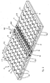
- a laser device is shown schematically as a processing device, a flow-generating device with a draw-off device 11 and a pressure-generating device 6 which delivers a pressurized fluid, eg nitrogen or another gas or gas mixture, here air.
- the disk-shaped workpiece 5 is, for example, a glass plate, a ceramic plate or another plate of brittle substrate material to be processed by means of the laser device.
- the disk-shaped workpiece 5 is a substrate ceramic plate or a glass substrate plate.
- the table 2 consists essentially of a table top 2.1, which forms an upwardly facing support surface. It comprises two segments, which are formed as two equal rectangular halves 2.11 and 2.12. The upper sides 17.1 and 17.2 of the segments 2.11, 2.12 each form a surface portion of the support surface of the table 2, which faces the disk-shaped workpiece 5, and have on its surface manifold outlets 15 from which pressurized air flows out, and numerous exhaust ports 14, over the Pressurized air from the Upper sides 17.1, 17.2 of the plate halves 2.11 and 2.12 is at least partially sucked.
- the discharge openings 14 are formed on the upper side 17.2 of the plate half 2.12 and on the upper side 17.1 of the plate half 2.11 as open at the top grooves, depressions or channels, which in plan view in each case a zigzag or snake-shaped withdrawal cross-section substantially over the entire width B. of the table top halves 2.12 or 2.11 without interruption. So are in Fig. 2 six discharge openings 14 are shown with the same shape, which are seen in the feed direction of the workpiece 5, so seen in the longitudinal direction L of the table 2, equidistant behind the other.
- the table half 2.11 has six equidistant behind each other, serpentine discharge openings 14.
- the discharge openings 14 are distributed substantially uniformly over the entire top 17.1 and 17.2 of the table top halves 2.12 and 2.11 so that a uniform removal of the gaseous medium on the table top surface away are ensured can.
- discharge openings 15 and outlet nozzles are formed with a circular outlet cross section equidistant behind each other in the longitudinal direction L as well as in the width direction B of the table top 2.1 seen.
- Their diameter is preferably between 0.1 mm and 2 mm, but may be between 0.05 mm and 10 mm, depending on the application.
- the outflow openings 15 are in Fig.
- a gap 16 or free space is provided, which extends over the entire width of the table 2 by way of example.
- a square 18 of the table 2 is inserted, the top of which is flush with the top 17.2 of the tabletop half 2.12, i.e., the top of the square 18 is coplanar with the top 17.2 of the tabletop half 2.12.
- a further square 19 is inserted into the gap 16 at a distance, the top of which extends flush with the top 17.1 of the tabletop half 2.11, i. whose top is coplanar with the top 17.1 of the table top half 2.11.
- Two rows of outflow openings 18.1 are formed on the upper side of the square 18, wherein the outflow openings 18.1 per row are formed equidistantly in succession over the entire width of the table top 2.1 or the length of the square 18.
- the two rows of outflow openings 18.1 are provided at a distance from one another and parallel to one another.
- a number of outlet openings 18.2 is distributed over the entire length of the square 18, wherein the individual outlet openings 18.2 are in turn arranged equidistantly in succession.
- two outflow openings are thus respectively arranged approximately on an imaginary center line between these two exhaust ports 18.2.
- each two outflow openings 18.1 thus not on a common, imaginary line with the adjacent exhaust port 18.2, but the outflow 18.1 are offset from the exhaust ports 18.2.
- the exhaust ports 18.2 and 18.1 Ausströmö réelleen the square 18 are evenly distributed over the top.
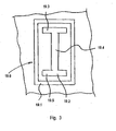
- the square 19 has on its upper side a plurality of opening groups 19.6 (see. Fig. 3 ), which are arranged in a row equidistant successively over the entire width B of the table 2 or along the entire length of the square 19.
- Each opening group 19.6 has a discharge opening 19.2 and an outflow opening 19.1, which surrounds the discharge opening 19.2 frame-shaped or annular.
- the vent opening 19.2 has a longitudinal section 19.4 extending in the longitudinal direction of the square 19 and two transverse sections 19.5 and 19.3 which continuously adjoin the ends of the longitudinal section 19.4 and extend transversely to the longitudinal section 19.4.
- the discharge opening 19.2 thus has a double-T-shaped withdrawal cross section on the surface or upper side of the square 19.
- the discharge opening 19.1 has an outlet cross-section in the form of a rectangular frame which frames the double-T-shaped discharge opening 19.2 throughout.
- eleven of these opening groups 19.6 formed in series.
- the two embodiments shown and arrangements of the openings at the four edges 18, 19 are alternatives that correspond to preferred embodiments. Above all, they permit a slight sliding of the workpiece onto the surface section which follows the gap 16 in the direction of displacement.
- two identically formed square edges 18, 19 are used, but this does not have to be the case.
- All exhaust ports 14, 18.2 and 19.2 are fluid-continuous with a vent line network 13, e.g. via the discharge nozzle 14.1 and in the tabletop halves 2.11 and 2.12 trained channels that are only hinted reproduced in the drawings coupled.
- the drain line network 13 is in turn fluidly coupled to the draining device 11, which may be e.g. may be a diaphragm pump or water jet pump, and the gas or air from the top of the table top 2.1 and the square edge 18 and 19 deducted.
- a vacuum control valve 12 is arranged fluid-throughly, e.g. can be controlled by means of a microprocessor device and software and appropriate electronics.
- the outflow openings 15, 18.1 and 19.1 are connected to a pressure line network 8, e.g. are fluidly coupled via corresponding conduit stubs and inner channels in the tabletop halves 2.11 and 2.12 and in the square edges 18 and 19, the pressure line network 8 in turn being fluidly coupled to a pressure generating device 6, e.g. is designed as a compressor that provides the pressurized air on the output side.
- a pressure regulating valve 7 is installed throughout the fluid, which can be electronically controlled, again via e.g. a microprocessor device. As a result, pressures between 0.1 bar and 1.5 bar are set above the ambient pressure.
- the laser device comprises, for example, two laser units 3, 9 which emit a laser beam in the direction of the upper side of the table 2 or the table top 2.1 for processing an upper side of the disk-shaped workpiece 5 or one Laser beam toward the bottom of the disk-shaped workpiece 5 within the gap 16 between the table top halves 2.12 and 2.11 radiates to edit the bottom of the disk-shaped workpiece 5 with laser beams can.
- the first laser beam (cf. Fig. 1 ) passes from the laser unit 3 coming a focusing device 4, which focuses the laser beam on the top of the disc-shaped workpiece 5, while the second laser beam from the further laser unit 9 coming from a focusing device 10 passes, the laser beam on the underside of the disc-shaped workpiece 5 for processing focused.
- the disk-shaped workpiece 5 can thus be processed both on its underside and on its upper side simultaneously with the preferred embodiment of the device.
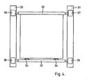
- the feed of the disk-shaped workpiece 5 in the longitudinal direction L of the table 2 is by means of a feed device ( Fig. 4 ). It comprises a linear guide with two rails 30, 31 attached to edge strips 21, which are arranged on the opposite side edges of the segments 2.11, 2.12 of the table 1, which run transversely across the gap 16. They can be designed as semi-circular profiles, for example.
- a receptacle for the workpiece 5 is guided, which consists of two longitudinally spaced independently displaceable brackets 32, 33.
- the first holder 32 has longitudinally acting stops for the edge of the workpiece, which allow to accurately position it in the receptacle, while the second holder 33 carries a pressing device, which consists for example of two arcuate steel springs 34, 35 or pneumatically actuated cylinders and presses the workpiece 5 against the stops.
- a pressing device which consists for example of two arcuate steel springs 34, 35 or pneumatically actuated cylinders and presses the workpiece 5 against the stops.
- Each of the two brackets 32, 33 is on both sides in the rails 30, 31 out.
- a drive device comprising linear motors 36, 37 and 38, 39, each with wheels tuned to the rails 30, 31, respectively driving the first holder 32 and the second holder 33, serves to engage the receiver in a precisely controllable manner with the workpiece 5 to slide over the gap 16 so that it can be processed successively by the laser beams 3, 9.
- the first holder 32 also has, for example, a pneumatic element for height adjustment, which makes it possible to adjust stops for supporting the workpiece in height.
- a pneumatic element for height adjustment which makes it possible to adjust stops for supporting the workpiece in height.
- the front edge of the workpiece 5 can be adjusted to a certain desired height.
- the remainder of the workpiece 5 is then adjusted to the same level by controlling the air cushion by means of the pressure regulating valves 7, 12.
- the workpiece 5 is contacted by the second holder 33 and pressed pressed regulated and thus fixed.
- a one-piece height-adjustable frame may be provided, on which the workpiece is placed.
- the laser beam emitted by the laser unit 3 or 9, together with the respectively associated focusing devices 4 and 10, respectively, can be moved across the width B of the table 2 or the workpiece 5 by means of a deflection device, e.g. a galvanomirror or a movable deflecting mirror, be distracted.
- a deflection device e.g. a galvanomirror or a movable deflecting mirror
- the feed or the leadership of the disc-shaped workpiece can be designed without contact, z. B. by appropriate control of the air flow or by laterally mounted additional Gaseinströmö réelleen. If the surface of the disk-shaped workpiece 5 to be processed, the pressure generating device 6 and the discharge device 11 are put into operation, whereby the pressure generating means 6 pressurized air through the pressure control valve 7 and the pressure line network 8 the outflow openings 15 of the two tabletop halves / segments 2.11 and 2.12 and the outflow openings 18.1 of the square 18 and the outflow openings 19.1 of the square 19 supplies. The pressurized air flows out of the discharge ports at the top of the table top halves 2.11 and 2.12 and the four-edge 18 and 19 at high pressure.
- the disk-shaped workpiece 5 is then placed on the table 2 and coupled as described with the feed device.
- the disk-shaped workpiece 5 is held raised above the top or surface of the table 2 by the generated air cushion.
- This storage of the disk-shaped workpiece 5 by air cushion is done uniformly over the entire table top or table surface, since the outflow openings 15 and the discharge openings 14 are evenly distributed up to the gap area. Since the disk-shaped workpiece 5 is thus mounted on an air cushion or a gas flow between the underside of the disk-shaped workpiece 5 and the tops 17.1 and 17.2 of the table 2, it can not come into contact with the top of the table 2.
- the pressure of the air flow at the top of the table 2 on the pressure difference between the supply side and the discharge side can be adjusted so that the disk-shaped workpiece 5 safely and quietly at a predetermined height, which corresponds to the machining height of the disk-shaped workpiece 5, is mounted on the generated air cushion between the disk-shaped workpiece 5 and the top of the table 2.
- the distance of the workpiece from the support surface can be adjusted approximately to a value between 0.01 mm and 1 mm, preferably between 0.05 mm and 0.3 mm.
- the precise adjustment of this processing height is especially important when the processing device is a laser device, since in this case the workpiece, or the area to be processed in the focus of the laser must be maintained.
- the height of the workpiece 5 can also be checked once by providing a measuring device with suitable measuring means which determine the height, for example interferometrically or by triangulation methods, and are arranged distributed in the gap 16 or over the table.
- suitable measuring means which determine the height, for example interferometrically or by triangulation methods, and are arranged distributed in the gap 16 or over the table.
- the workpiece 5 can be traversed once over the gap 16 and its uniform altitude be checked over, in the latter case, the review can be done quickly through the distributed measuring means.
- the height of the workpiece 5 can also be kept constant during processing by feedback.
- the workpiece 5 can be positioned with the aid of the measuring device over the gap with an accuracy of 50 .mu.m to 100 .mu.m, wherein the height of the workpiece measured by the measuring device with an accuracy of 1 .mu.m and then via a suitable control circuit by means of the pressure valves 7, 12th the gas pressure is regulated.
- the focus of the laser can also be controlled.
- various workpiece machining operations can be carried out while simultaneously machining the lower side and also the upper side of the workpiece 5.
- material can be removed from the top or bottom of the workpiece 5 with the laser beam to produce e.g. To be able to form conductor tracks on the workpiece, or the workpiece can be laser marked or scratched.
- a coating on the top side it is also possible for a coating on the top side to be processed through the workpiece 5 from the underside.
- a special case of material removal is the so-called "laser scribing", in which certain areas are to be electrically insulated on a flat, continuously conductive coated thin substrate.
- the conductive layer is selectively removed by means of a laser along a line (the method is known as laser ablation) and thus the adjacent surfaces are electrically insulated.
- the workpiece is mounted without contact on a table according to the invention on the gas or air cushion, reciprocated in the longitudinal direction L of the table 2 over the treatment device (laser) provided between the segments 2.11 and 2.12 in the gap 16.
- the movement in the transverse direction of the table can be achieved by the movement of the treatment device in the gap 16, in combination with the longitudinal movement can be described in a known manner lines on the substrate.
- markings on the workpiece which allow the positioning of the workpiece relative to the table or to the treatment device. These markings are advantageously carried out as crosses or orientation lines.
- the application the markings can be done in an upstream process, for. B. by printing or in a photolithographic exposure process.
- the marking can also be done with the inventive device via laser, z. B. in a first operation.
- a detector for the markings eg a pattern recognition device as measuring device. This can be done stationary in several places in or on the table, which allows to monitor several markers at the same time.
- the measuring device can also be provided in or above the gap 16, preferably on a moving device such as the processing device (laser) or even combined with it.
- the positional control over the markings also makes it possible to design the feed and guide devices in such a way that the precision of the positioning does not have to be ensured by them. This will be necessary in particular when the bearing and guide are non-contact or largely non-contact.
- the markings are also important if the substrate must be described several times, for. B. between different coating processes, each store the layers of material on the workpiece. It can thus be ensured that the orientation of the workpiece is recognized and the lines to be rewritten follow a predetermined pattern.
- the accuracy requirements are in such cases at 5 to 500 microns. However, accuracies of 10 ⁇ m are easily achievable when markers are restarted, especially since the control of the movement of the workpiece can still meet much higher accuracies requirements and can be for example 1 micron.
- the specified accuracies apply in each case for positioning transversely to the gap as well as parallel to the gap.
- the markers in the form of z. B. a bar code also serve to identify the workpiece.
- an individual description pattern per workpiece can be provided and the unique identification of the workpiece on the marking is guaranteed. If, in addition to a processing device, measuring and testing devices are also provided, the device thus also makes it possible to unambiguously allocate the device under test and the measured data.
- the device according to the invention can also be used for separating or cutting disk-shaped workpieces, for example glass plates or ceramic plates.
- the laser-induced cutting of plates can be used.
- the apparatus of the invention cuts the plate 5 by moving the laser beam along a cutting line, whereby the glass plate is heated along the cutting line but not melted.
- the heating of the plate along the cutting line is followed by cooling along the cutting line by a cooling medium, eg a cooled jet of air, which creates stresses along the cutting line in the plate resulting in a precise break of the glass sheet along the cutting line.
- the table may also have several consecutive gaps, e.g. are separated by four-edge and in each of which a processing device is arranged. This allows several processing operations to take place simultaneously.
Landscapes
- Engineering & Computer Science (AREA)
- Physics & Mathematics (AREA)
- Chemical & Material Sciences (AREA)
- Optics & Photonics (AREA)
- Mechanical Engineering (AREA)
- Materials Engineering (AREA)
- Organic Chemistry (AREA)
- Plasma & Fusion (AREA)
- Health & Medical Sciences (AREA)
- Toxicology (AREA)
- Thermal Sciences (AREA)
- Laser Beam Processing (AREA)
- Electrical Discharge Machining, Electrochemical Machining, And Combined Machining (AREA)
- Re-Forming, After-Treatment, Cutting And Transporting Of Glass Products (AREA)
- Jigs For Machine Tools (AREA)
- Drying Of Semiconductors (AREA)
- Container, Conveyance, Adherence, Positioning, Of Wafer (AREA)
- Multi-Process Working Machines And Systems (AREA)
- Polishing Bodies And Polishing Tools (AREA)
- Machine Tool Units (AREA)
Claims (17)
- Table (2) comportant une surface d'appui plane destinée à recevoir une pièce (5), la surface d'appui étant constituée d'au moins deux sections de surface qui se suivent l'une l'autre dans une direction longitudinale et sont séparées par un intervalle (16) s'étendant transversalement à la direction longitudinale et des orifices d'échappement (15) répartis sur les sections de surface, servant à amener du gaz comprimé en vue de produire un coussin de gaz entre la section de surface respective et la face inférieure de la pièce (5), ainsi qu'un dispositif d'avance de la pièce, qui est apte à déplacer ladite pièce dans la direction longitudinale en traversant l'intervalle (16) et un dispositif d'usinage destiné à usiner la pièce (5), caractérisée en ce que le dispositif d'usinage est disposé au-dessous de l'intervalle (16) et le dispositif d'avance comprend un guidage linéaire traversant l'intervalle (16) dans la direction longitudinale avec deux rails (30, 31) parallèles écartés l'un de l'autre transversalement à la direction longitudinale, ainsi qu'un logement pour la pièce (5) avec un premier support (32) et un deuxième support (33) écarté du premier dans la direction longitudinale, lesquels sont guidés chacun dans les deux rails (30, 31), et un dispositif d'entraînement qui est apte à déplacer le logement le long du guidage linéaire.
- Table (2) selon la revendication 1, caractérisée en ce que le premier support (32) présente des butées pour la pièce (5) agissant dans la direction longitudinale et le deuxième support (33) un dispositif de pression qui est apte à presser la pièce (5) contre les butées.
- Table (2) selon la revendication 1 ou 2, caractérisée en ce que le dispositif d'entraînement comprend au moins un moteur linéaire (36, 37 ; 38, 39) relié respectivement au premier support (32) et au deuxième support (33).
- Table (2) selon l'une des revendications 1 à 3, caractérisée en ce qu'elle comprend un dispositif d'identification de modèle servant à identifier des marques de référence sur la pièce (5) et leur position.
- Table (2) selon l'une des revendications 1 à 4, caractérisée en ce qu'elle comprend un autre dispositif d'usinage destiné à usiner la pièce (5) et disposé au-dessus de l'intervalle (16).
- Table (2) selon la revendication 1 à 5, caractérisée en ce que le dispositif d'usinage comprend au moins une unité laser (3, 9) orientée vers l'intervalle (16).
- Table (2) selon la revendication 6, caractérisée en ce que le foyer de l'unité laser (3, 9) est réglable en hauteur.
- Table (2) selon l'une des revendications 1 à 7, caractérisée en ce que les orifices d'échappement (15) sont répartis essentiellement régulièrement sur chaque section de surface.
- Table (2) selon l'une des revendications 1 à 8, caractérisée en ce que les orifices d'échappement (15) sont ronds au moins en partie et présentent chacun de préférence un diamètre compris entre 0,05 mm et 10 mm, en particulier entre 0,1 mm et 2 mm.
- Table (2) selon l'une des revendications 1 à 9, caractérisée en ce que des orifices d'évacuation (14) sont répartis sur les sections de surface pour évacuer du gaz comprimé.
- Table (2) selon la revendication 10, caractérisée en ce que les orifices d'évacuation (14) sont réalisés au moins en partie sous la forme de fentes d'évacuation qui sont approximativement parallèles à l'intervalle (16) et réparties régulièrement sur les sections de surface dans la direction longitudinale.
- Table (2) selon la revendication 11, caractérisée en ce que les fentes d'évacuation suivent respectivement une ligne en zigzag.
- Table (2) selon l'une des revendications 10 à 12, caractérisée en ce que des orifices d'évacuation (18.2, 19.2), qui sont entourés chacun par un orifice d'échappement (18.1, 19.1) formant une fente fermée, sont disposés au moins de part et d'autre de l'intervalle (16).
- Table (2) selon la revendication 13, caractérisée en ce que l'orifice d'évacuation (19.2) est réalisé sous la forme d'une fente approximativement en double T et l'orifice d'échappement (19.1) qui l'entoure sous la forme d'une fente formant un cadre rectangulaire.
- Procédé d'usinage d'une pièce (5) sur une table (2) selon l'une des revendications 1 à 14, caractérisé en ce que la pièce (5) est fixée dans le logement puis déplacée avec celui-ci en traversant l'intervalle (16), et en même temps est usinée à travers de l'intervalle (16) par le dispositif d'usinage disposé au-dessous de l'intervalle (16).
- Procédé selon la revendication 15, caractérisé en ce qu'il comprend l'usinage au moyen d'un faisceau laser.
- Procédé selon la revendication 16, caractérisé en ce que la pièce (5) est transparente au faisceau laser et qu'une couche disposée sur la surface de celle-ci est usinée.
Priority Applications (1)
| Application Number | Priority Date | Filing Date | Title |
|---|---|---|---|
| EP20100005381 EP2216276A3 (fr) | 2004-06-03 | 2005-05-27 | Appareil de travail et de positionement d'un matériel, et méthode associée |
Applications Claiming Priority (2)
| Application Number | Priority Date | Filing Date | Title |
|---|---|---|---|
| CH9352004 | 2004-06-03 | ||
| PCT/CH2005/000300 WO2005118440A1 (fr) | 2004-06-03 | 2005-05-27 | Etabli de reception d'une piece et procede de traitement d'une piece sur un tel etabli |
Related Child Applications (1)
| Application Number | Title | Priority Date | Filing Date |
|---|---|---|---|
| EP10005381.8 Division-Into | 2010-05-22 |
Publications (2)
| Publication Number | Publication Date |
|---|---|
| EP1753679A1 EP1753679A1 (fr) | 2007-02-21 |
| EP1753679B1 true EP1753679B1 (fr) | 2010-08-04 |
Family
ID=34968081
Family Applications (2)
| Application Number | Title | Priority Date | Filing Date |
|---|---|---|---|
| EP20050742263 Expired - Lifetime EP1753679B1 (fr) | 2004-06-03 | 2005-05-27 | Etabli de reception d'une piece et procede de traitement d'une piece sur un tel etabli |
| EP20100005381 Withdrawn EP2216276A3 (fr) | 2004-06-03 | 2005-05-27 | Appareil de travail et de positionement d'un matériel, et méthode associée |
Family Applications After (1)
| Application Number | Title | Priority Date | Filing Date |
|---|---|---|---|
| EP20100005381 Withdrawn EP2216276A3 (fr) | 2004-06-03 | 2005-05-27 | Appareil de travail et de positionement d'un matériel, et méthode associée |
Country Status (10)
| Country | Link |
|---|---|
| US (1) | US8785812B2 (fr) |
| EP (2) | EP1753679B1 (fr) |
| JP (1) | JP4899062B2 (fr) |
| KR (1) | KR101215147B1 (fr) |
| CN (1) | CN1997575B (fr) |
| AT (1) | ATE476386T1 (fr) |
| BR (1) | BRPI0511797A (fr) |
| DE (2) | DE502005010044D1 (fr) |
| IL (1) | IL179554A (fr) |
| WO (1) | WO2005118440A1 (fr) |
Families Citing this family (46)
| Publication number | Priority date | Publication date | Assignee | Title |
|---|---|---|---|---|
| KR100721550B1 (ko) * | 2006-01-19 | 2007-05-23 | 주식회사 태성기연 | 판유리 이송장치 |
| JP2007246298A (ja) * | 2006-03-13 | 2007-09-27 | Shibuya Kogyo Co Ltd | 脆性材料の割断方法とその装置 |
| JP5293601B2 (ja) * | 2007-06-06 | 2013-09-18 | 三星ダイヤモンド工業株式会社 | マルチヘッド搭載スクライブ装置及びチップホルダの自動交換システム |
| KR100786126B1 (ko) * | 2007-08-14 | 2007-12-18 | 주식회사 아바코 | 비접촉 방식에 의한 피절단물의 평탄도를 유지하는스크라이브 헤드 장치 및 그 스크라이브 방법 |
| JP4231538B1 (ja) * | 2007-12-12 | 2009-03-04 | 株式会社片岡製作所 | レーザ加工機 |
| ES2374685T3 (es) * | 2008-06-25 | 2012-02-21 | Atec Holding Ag | Dispositivo de estructuración de un módulo solar. |
| JP2010069517A (ja) * | 2008-09-19 | 2010-04-02 | Disco Abrasive Syst Ltd | 加工装置および加工方法 |
| CN102203943B (zh) * | 2008-10-29 | 2013-07-31 | 欧瑞康太阳能股份公司(特吕巴赫) | 通过多激光束照射将在基板上形成的半导体膜划分成多个区域的方法 |
| US8528886B2 (en) * | 2009-02-02 | 2013-09-10 | Corning Incorporated | Material sheet handling system and processing methods |
| JP2012055966A (ja) * | 2010-09-13 | 2012-03-22 | Disco Corp | レーザー加工装置 |
| CN102363476B (zh) * | 2011-09-29 | 2016-01-27 | 柳州市中晶科技有限公司 | 气悬浮传送装置 |
| TWI586612B (zh) * | 2011-11-18 | 2017-06-11 | 康寧公司 | 用於修整移動玻璃帶之設備及方法 |
| JP5996308B2 (ja) * | 2012-07-10 | 2016-09-21 | コマツNtc株式会社 | ワイヤソー |
| KR20150084758A (ko) * | 2012-11-13 | 2015-07-22 | 니폰 덴키 가라스 가부시키가이샤 | 판 유리의 제조 방법 및 제조 장치 |
| JP6364789B2 (ja) * | 2014-01-29 | 2018-08-01 | 三星ダイヤモンド工業株式会社 | スクライブ装置 |
| US20170080522A1 (en) * | 2014-04-01 | 2017-03-23 | Pansonic Intellectual Property Management Co., Ltd | Laser processing machine and laser processing method |
| CN104108605B (zh) * | 2014-07-08 | 2016-08-17 | 深圳市华星光电技术有限公司 | 一种玻璃基板的取放装置 |
| US9613815B2 (en) * | 2014-11-24 | 2017-04-04 | Ultratech, Inc. | High-efficiency line-forming optical systems and methods for defect annealing and dopant activation |
| DE102016104273B4 (de) * | 2016-03-09 | 2021-02-04 | Hegla Gmbh & Co. Kg | Verfahren und Vorrichtung zur Behandlung von Flachglaseinheiten an einer glasverarbeitenden Anlage und Glasverarbeitende Anlage |
| EP3472077A4 (fr) * | 2016-06-21 | 2020-03-04 | Coreflow Ltd | Plate-forme support sans contact avec levage du bord |
| US20180118602A1 (en) * | 2016-11-01 | 2018-05-03 | Corning Incorporated | Glass sheet transfer apparatuses for laser-based machining of sheet-like glass substrates |
| CN106746563A (zh) * | 2016-12-25 | 2017-05-31 | 信宜市茂森科技实业有限公司 | 掰玻璃机构 |
| US9889995B1 (en) * | 2017-03-15 | 2018-02-13 | Core Flow Ltd. | Noncontact support platform with blockage detection |
| CN107838525A (zh) * | 2017-10-13 | 2018-03-27 | 严敏努 | 一种钢板切割机 |
| CN107755852B (zh) * | 2017-10-13 | 2020-04-21 | 陈启健 | 一种除渣的钢板切割机 |
| CN107671391B (zh) * | 2017-10-13 | 2020-04-03 | 上海洪铺钢结构工程有限公司 | 一种高效坡口处理、自动除渣的钢板切割机 |
| CN107838526A (zh) * | 2017-10-13 | 2018-03-27 | 严敏努 | 一种桥梁钢板切割机 |
| CN107838523A (zh) * | 2017-10-13 | 2018-03-27 | 严敏努 | 一种新型的桥梁钢板切割方法 |
| CN107838530A (zh) * | 2017-10-13 | 2018-03-27 | 严敏努 | 一种带除渣装置的桥梁钢板切割机 |
| CN107755853A (zh) * | 2017-10-13 | 2018-03-06 | 严敏努 | 一种桥梁钢板切割方法 |
| CN107838529A (zh) * | 2017-10-13 | 2018-03-27 | 严敏努 | 一种新型的桥梁钢板切割机 |
| CN107838522B (zh) * | 2017-10-13 | 2020-04-17 | 陈启健 | 一种除渣的钢板切割方法 |
| CN107755851B (zh) * | 2017-10-13 | 2020-01-21 | 唐山市丰润区久海机械制造有限公司 | 一种高效坡口处理、自动除渣的钢板切割方法 |
| CN107838528B (zh) * | 2017-10-13 | 2020-04-14 | 陈启健 | 一种完全除渣的桥梁钢板切割方法 |
| CN107838524A (zh) * | 2017-10-13 | 2018-03-27 | 严敏努 | 一种除渣的桥梁钢板切割方法 |
| CN107838527B (zh) * | 2017-10-13 | 2020-04-14 | 包伟松 | 一种完全除渣的桥梁钢板切割机 |
| US10745215B2 (en) * | 2018-12-27 | 2020-08-18 | Core Flow Ltd. | Port arrangement for noncontact support platform |
| CN110550853A (zh) * | 2019-09-27 | 2019-12-10 | 萧县威辰机电工程设备有限公司 | 一种能够裁剪不规则玻璃的玻璃切割设备 |
| WO2021131559A1 (fr) * | 2019-12-24 | 2021-07-01 | 日本電気硝子株式会社 | Procédé de production de feuille de verre, procédé de production de rouleau de verre et dispositif de production de feuille de verre |
| JP7437186B2 (ja) * | 2020-02-26 | 2024-02-22 | Jswアクティナシステム株式会社 | 浮上搬送装置、及びレーザ処理装置 |
| CN114043103B (zh) * | 2021-11-08 | 2024-11-15 | 南京魔迪多维数码科技有限公司 | 一种免于激光切割伤害的气动悬浮装置 |
| DE102022102162A1 (de) * | 2022-01-31 | 2023-08-03 | Eitzenberger Luftlagertechnik Gmbh | Floating Unit |
| AT526274A2 (de) * | 2022-06-15 | 2024-01-15 | Trotec Laser Gmbh | Laserplotter |
| CN115922126B (zh) * | 2023-01-10 | 2025-03-14 | 广东科技学院 | 一种用于优化电子玻璃刻蚀加工平面度的微孔气流装置及刻蚀方法 |
| CN116252168A (zh) * | 2023-03-10 | 2023-06-13 | 赫比(上海)金属工业有限公司 | 一种夹持装置与方法及加工设备 |
| CN117125480B (zh) * | 2023-08-30 | 2025-09-16 | 蚌埠凯盛工程技术有限公司 | 一种皮带式气浮桌及其制作方法 |
Family Cites Families (35)
| Publication number | Priority date | Publication date | Assignee | Title |
|---|---|---|---|---|
| NL130417C (fr) * | 1961-06-16 | 1900-01-01 | ||
| NL137693C (fr) | 1964-03-25 | |||
| FR1400501A (fr) * | 1964-04-16 | 1965-05-28 | Procédé d'attraction contrôlée et dispositif pour sa mise en oeuvre | |
| FR1527937A (fr) * | 1967-03-31 | 1968-06-07 | Saint Gobain | Dispositif de transport d'un matériau en forme de feuille sur un coussin gazeux |
| FR2044988A5 (fr) * | 1969-05-29 | 1971-02-26 | Saint Gobain | |
| BE795259A (fr) * | 1972-02-10 | 1973-08-09 | Saint Gobain | Dispositif generateur de coussins gazeux pour le support de feuilles du rubans |
| IT1170251B (it) * | 1982-11-18 | 1987-06-03 | Manfred Fennesz | Impianto per il condizionamento di un ambiente |
| US4895244A (en) * | 1986-07-28 | 1990-01-23 | Libbey-Owens-Ford Co. | Apparatus for aligning glass sheets in a production line |
| JPH062597B2 (ja) | 1987-07-02 | 1994-01-12 | 三星ダイヤモンド工業株式会社 | 自動ガラススクライバ− |
| US5003729A (en) * | 1988-10-11 | 1991-04-02 | Ppg Industries, Inc. | Support system for abrasive jet cutting |
| JPH0357437A (ja) * | 1989-07-25 | 1991-03-12 | Agency Of Ind Science & Technol | Mri断層像立体視装置 |
| ES2052239T3 (es) * | 1990-12-13 | 1994-07-01 | Gfm Fertigungstechnik | Maquina herramienta, especialmente maquina cortadora. |
| US5078775A (en) * | 1991-03-19 | 1992-01-07 | Glasstech, Inc. | Glass sheet gas support |
| JP3157851B2 (ja) * | 1991-06-10 | 2001-04-16 | 株式会社アマダ | レーザ加工機 |
| JPH0710266A (ja) | 1993-06-29 | 1995-01-13 | Metsukusu:Kk | クリーンルーム用搬送装置 |
| AT403908B (de) * | 1994-07-04 | 1998-06-25 | Lisec Peter | Anordnung zum teilen von verbundglas |
| JPH08143323A (ja) | 1994-11-18 | 1996-06-04 | Asahi Glass Co Ltd | 板状体の搬送方法及び装置 |
| KR970008386A (ko) * | 1995-07-07 | 1997-02-24 | 하라 세이지 | 기판의 할단(割斷)방법 및 그 할단장치 |
| US5762674A (en) * | 1995-09-27 | 1998-06-09 | Glasstech, Inc. | Apparatus for coating glass sheet ribbon |
| DE19620234A1 (de) * | 1996-05-20 | 1997-11-27 | Holtronic Technologies Ltd | Verfahren und Vorrichtung zum Positionieren eines Substrats |
| JPH09320939A (ja) | 1996-05-29 | 1997-12-12 | Nikon Corp | 位置検出方法及び装置 |
| JPH1058173A (ja) * | 1996-08-27 | 1998-03-03 | Nikon Corp | レーザ加工装置 |
| US6173648B1 (en) * | 1997-10-24 | 2001-01-16 | Sharp Kabushiki Kaisha | Manufacturing method of liquid crystal display element and manufacturing apparatus of the same |
| AU1937400A (en) * | 1998-12-09 | 2000-06-26 | Billco Manufacturing Inc. | Process and apparatus for processing and transporting flat glass workpieces |
| JP2002172479A (ja) * | 2000-09-20 | 2002-06-18 | Seiko Epson Corp | レーザ割断方法、レーザ割断装置、液晶装置の製造方法並びに液晶装置の製造装置 |
| JP4038133B2 (ja) * | 2002-02-28 | 2008-01-23 | 芝浦メカトロニクス株式会社 | 基板貼り合わせ装置及び方法並びに基板検出装置 |
| JP4247734B2 (ja) * | 2002-03-05 | 2009-04-02 | コニカミノルタホールディングス株式会社 | インクジェットプリンタヘッドの製造方法及びインクジェットプリンタヘッド |
| JP4141720B2 (ja) * | 2002-03-29 | 2008-08-27 | 株式会社アマダ | 熱切断加工機 |
| JP2003300618A (ja) * | 2002-04-10 | 2003-10-21 | Orc Mfg Co Ltd | 基板搬送機構 |
| JP4107639B2 (ja) * | 2002-04-15 | 2008-06-25 | 本田技研工業株式会社 | レーザ溶接装置およびレーザ溶接方法 |
| TWI226303B (en) | 2002-04-18 | 2005-01-11 | Olympus Corp | Substrate carrying device |
| JP2004050246A (ja) * | 2002-07-22 | 2004-02-19 | Rezakku:Kk | レーザ加工装置 |
| JP2004114066A (ja) * | 2002-09-25 | 2004-04-15 | Takano Co Ltd | レーザ加工装置 |
| RU2266263C2 (ru) * | 2002-10-04 | 2005-12-20 | Текнопат Аг | Способ перемещения и позиционирования листов стекла и устройство для его осуществления |
| US7040204B2 (en) * | 2002-10-30 | 2006-05-09 | Mikkelsen Graphic Engineering | Method for preparing graphics on sheets |
-
2005
- 2005-05-27 DE DE200550010044 patent/DE502005010044D1/de not_active Expired - Lifetime
- 2005-05-27 EP EP20050742263 patent/EP1753679B1/fr not_active Expired - Lifetime
- 2005-05-27 CN CN2005800177937A patent/CN1997575B/zh not_active Expired - Fee Related
- 2005-05-27 JP JP2007513651A patent/JP4899062B2/ja not_active Expired - Fee Related
- 2005-05-27 DE DE200520021717 patent/DE202005021717U1/de not_active Expired - Lifetime
- 2005-05-27 WO PCT/CH2005/000300 patent/WO2005118440A1/fr not_active Ceased
- 2005-05-27 EP EP20100005381 patent/EP2216276A3/fr not_active Withdrawn
- 2005-05-27 US US11/597,856 patent/US8785812B2/en not_active Expired - Fee Related
- 2005-05-27 BR BRPI0511797-6A patent/BRPI0511797A/pt not_active IP Right Cessation
- 2005-05-27 KR KR1020077000126A patent/KR101215147B1/ko not_active Expired - Fee Related
- 2005-05-27 AT AT05742263T patent/ATE476386T1/de active
-
2006
- 2006-11-23 IL IL179554A patent/IL179554A/en not_active IP Right Cessation
Also Published As
| Publication number | Publication date |
|---|---|
| EP2216276A3 (fr) | 2011-06-29 |
| CN1997575B (zh) | 2012-06-20 |
| KR20070041494A (ko) | 2007-04-18 |
| DE502005010044D1 (de) | 2010-09-16 |
| JP4899062B2 (ja) | 2012-03-21 |
| JP2008501526A (ja) | 2008-01-24 |
| BRPI0511797A (pt) | 2008-01-15 |
| DE202005021717U1 (de) | 2009-08-27 |
| US8785812B2 (en) | 2014-07-22 |
| WO2005118440A1 (fr) | 2005-12-15 |
| EP2216276A2 (fr) | 2010-08-11 |
| IL179554A (en) | 2011-09-27 |
| EP1753679A1 (fr) | 2007-02-21 |
| US20070228630A1 (en) | 2007-10-04 |
| ATE476386T1 (de) | 2010-08-15 |
| IL179554A0 (en) | 2007-05-15 |
| KR101215147B1 (ko) | 2012-12-24 |
| CN1997575A (zh) | 2007-07-11 |
Similar Documents
| Publication | Publication Date | Title |
|---|---|---|
| EP1753679B1 (fr) | Etabli de reception d'une piece et procede de traitement d'une piece sur un tel etabli | |
| DE10041519C1 (de) | Verfahren und Vorrichtung zum Durchschneiden einer Flachglasplatte in mehrere Rechteckplatten | |
| DE102006058536B4 (de) | Laserstrahlbearbeitungsmaschine | |
| DE3242944A1 (de) | Luftkissentransportsystem | |
| EP0983827A1 (fr) | Machine de découpe au jet d'eau | |
| DE102017202426A1 (de) | TLS-Verfahren und TLS-Vorrichtung | |
| EP2186595A1 (fr) | Dispositif de fabrication de modules de cellules solaires à couches minces | |
| DE102005062230A1 (de) | Verfahren und Vorrichtung zum Trennen von Scheiben aus sprödem Material, insbesondere von Wafern | |
| EP0489681B1 (fr) | Procédé et dispositif pour déplacer des pièces en forme de bandes ou de panneaux, empilés et juxtaposés sur une surface de support à faible coefficient de frottement | |
| EP2556005B1 (fr) | Dispositif de coussin d'air | |
| WO2012062296A2 (fr) | Dispositif de structuration très précise de modules de cellules solaires à couches minces | |
| EP3189920A1 (fr) | Dispositif de fixation, machine d'usinage par électro-érosion ou installation laser et procédé d'usinage par électro-érosion ou par laser | |
| DE102004009950A1 (de) | Vorrichtung mit Bearbeitungskopf, zugehöriges Verfahren und Sensor | |
| DE19500400C2 (de) | Auflagersystem für mit Kunststoffolie zu überziehende plattenförmige Werkstücke | |
| EP2958752B1 (fr) | Dispositif de traitement de surface | |
| EP3650163B1 (fr) | Machine d'usinage par séparation d'une pièce en forme de plaque et méthode de déplacement d'un chariot support dans cette machine | |
| AT402704B (de) | Bearbeitungsvorrichtung für plattenförmige werkstücke, insbesondere plattenaufteilsäge | |
| DE102004062374B4 (de) | Verfahren und Vorrichtung zum automatischen Bearbeiten von nichtmetallischen, nachgiebigen Werkstücken | |
| WO2013117301A1 (fr) | Procédé et dispositif pour séparer parallèlement une pièce en plusieurs morceaux | |
| DE102023100969A1 (de) | Vorrichtung und Verfahren zur Laserbearbeitung | |
| DE3401856C2 (de) | Kontaktkopiereinrichtung | |
| DE3933264A1 (de) | Holzbearbeitungsmaschine, insbesondere kehlmaschine | |
| DE8401543U1 (de) | Kontaktkopiereinrichtung | |
| DD288033A5 (de) | Vorrichtung zum ritzen | |
| JPH0580699U (ja) | 基板分割装置 |
Legal Events
| Date | Code | Title | Description |
|---|---|---|---|
| PUAI | Public reference made under article 153(3) epc to a published international application that has entered the european phase |
Free format text: ORIGINAL CODE: 0009012 |
|
| 17P | Request for examination filed |
Effective date: 20061125 |
|
| AK | Designated contracting states |
Kind code of ref document: A1 Designated state(s): AT BE BG CH CY CZ DE DK EE ES FI FR GB GR HU IE IS IT LI LT LU MC NL PL PT RO SE SI SK TR |
|
| 17Q | First examination report despatched |
Effective date: 20070803 |
|
| DAX | Request for extension of the european patent (deleted) | ||
| RAP1 | Party data changed (applicant data changed or rights of an application transferred) |
Owner name: OERLIKON TRADING AG, TRUEBBACH |
|
| R17C | First examination report despatched (corrected) |
Effective date: 20080206 |
|
| GRAP | Despatch of communication of intention to grant a patent |
Free format text: ORIGINAL CODE: EPIDOSNIGR1 |
|
| GRAS | Grant fee paid |
Free format text: ORIGINAL CODE: EPIDOSNIGR3 |
|
| RAP1 | Party data changed (applicant data changed or rights of an application transferred) |
Owner name: OERLIKON SOLAR IP AG, TRUEBBACH |
|
| GRAA | (expected) grant |
Free format text: ORIGINAL CODE: 0009210 |
|
| AK | Designated contracting states |
Kind code of ref document: B1 Designated state(s): AT BE BG CH CY CZ DE DK EE ES FI FR GB GR HU IE IS IT LI LT LU MC NL PL PT RO SE SI SK TR |
|
| REG | Reference to a national code |
Ref country code: GB Ref legal event code: FG4D Free format text: NOT ENGLISH |
|
| REG | Reference to a national code |
Ref country code: CH Ref legal event code: EP |
|
| REG | Reference to a national code |
Ref country code: IE Ref legal event code: FG4D Free format text: LANGUAGE OF EP DOCUMENT: GERMAN |
|
| REF | Corresponds to: |
Ref document number: 502005010044 Country of ref document: DE Date of ref document: 20100916 Kind code of ref document: P |
|
| REG | Reference to a national code |
Ref country code: NL Ref legal event code: VDEP Effective date: 20100804 |
|
| LTIE | Lt: invalidation of european patent or patent extension |
Effective date: 20100804 |
|
| PG25 | Lapsed in a contracting state [announced via postgrant information from national office to epo] |
Ref country code: LT Free format text: LAPSE BECAUSE OF FAILURE TO SUBMIT A TRANSLATION OF THE DESCRIPTION OR TO PAY THE FEE WITHIN THE PRESCRIBED TIME-LIMIT Effective date: 20100804 Ref country code: FI Free format text: LAPSE BECAUSE OF FAILURE TO SUBMIT A TRANSLATION OF THE DESCRIPTION OR TO PAY THE FEE WITHIN THE PRESCRIBED TIME-LIMIT Effective date: 20100804 Ref country code: NL Free format text: LAPSE BECAUSE OF FAILURE TO SUBMIT A TRANSLATION OF THE DESCRIPTION OR TO PAY THE FEE WITHIN THE PRESCRIBED TIME-LIMIT Effective date: 20100804 |
|
| PG25 | Lapsed in a contracting state [announced via postgrant information from national office to epo] |
Ref country code: PT Free format text: LAPSE BECAUSE OF FAILURE TO SUBMIT A TRANSLATION OF THE DESCRIPTION OR TO PAY THE FEE WITHIN THE PRESCRIBED TIME-LIMIT Effective date: 20101206 Ref country code: BG Free format text: LAPSE BECAUSE OF FAILURE TO SUBMIT A TRANSLATION OF THE DESCRIPTION OR TO PAY THE FEE WITHIN THE PRESCRIBED TIME-LIMIT Effective date: 20101104 Ref country code: CY Free format text: LAPSE BECAUSE OF FAILURE TO SUBMIT A TRANSLATION OF THE DESCRIPTION OR TO PAY THE FEE WITHIN THE PRESCRIBED TIME-LIMIT Effective date: 20100804 Ref country code: IS Free format text: LAPSE BECAUSE OF FAILURE TO SUBMIT A TRANSLATION OF THE DESCRIPTION OR TO PAY THE FEE WITHIN THE PRESCRIBED TIME-LIMIT Effective date: 20101204 Ref country code: PL Free format text: LAPSE BECAUSE OF FAILURE TO SUBMIT A TRANSLATION OF THE DESCRIPTION OR TO PAY THE FEE WITHIN THE PRESCRIBED TIME-LIMIT Effective date: 20100804 Ref country code: SI Free format text: LAPSE BECAUSE OF FAILURE TO SUBMIT A TRANSLATION OF THE DESCRIPTION OR TO PAY THE FEE WITHIN THE PRESCRIBED TIME-LIMIT Effective date: 20100804 |
|
| REG | Reference to a national code |
Ref country code: IE Ref legal event code: FD4D |
|
| PG25 | Lapsed in a contracting state [announced via postgrant information from national office to epo] |
Ref country code: SE Free format text: LAPSE BECAUSE OF FAILURE TO SUBMIT A TRANSLATION OF THE DESCRIPTION OR TO PAY THE FEE WITHIN THE PRESCRIBED TIME-LIMIT Effective date: 20100804 Ref country code: GR Free format text: LAPSE BECAUSE OF FAILURE TO SUBMIT A TRANSLATION OF THE DESCRIPTION OR TO PAY THE FEE WITHIN THE PRESCRIBED TIME-LIMIT Effective date: 20101105 |
|
| PG25 | Lapsed in a contracting state [announced via postgrant information from national office to epo] |
Ref country code: IE Free format text: LAPSE BECAUSE OF FAILURE TO SUBMIT A TRANSLATION OF THE DESCRIPTION OR TO PAY THE FEE WITHIN THE PRESCRIBED TIME-LIMIT Effective date: 20100804 Ref country code: DK Free format text: LAPSE BECAUSE OF FAILURE TO SUBMIT A TRANSLATION OF THE DESCRIPTION OR TO PAY THE FEE WITHIN THE PRESCRIBED TIME-LIMIT Effective date: 20100804 |
|
| PG25 | Lapsed in a contracting state [announced via postgrant information from national office to epo] |
Ref country code: IT Free format text: LAPSE BECAUSE OF FAILURE TO SUBMIT A TRANSLATION OF THE DESCRIPTION OR TO PAY THE FEE WITHIN THE PRESCRIBED TIME-LIMIT Effective date: 20100804 Ref country code: CZ Free format text: LAPSE BECAUSE OF FAILURE TO SUBMIT A TRANSLATION OF THE DESCRIPTION OR TO PAY THE FEE WITHIN THE PRESCRIBED TIME-LIMIT Effective date: 20100804 Ref country code: RO Free format text: LAPSE BECAUSE OF FAILURE TO SUBMIT A TRANSLATION OF THE DESCRIPTION OR TO PAY THE FEE WITHIN THE PRESCRIBED TIME-LIMIT Effective date: 20100804 Ref country code: SK Free format text: LAPSE BECAUSE OF FAILURE TO SUBMIT A TRANSLATION OF THE DESCRIPTION OR TO PAY THE FEE WITHIN THE PRESCRIBED TIME-LIMIT Effective date: 20100804 Ref country code: EE Free format text: LAPSE BECAUSE OF FAILURE TO SUBMIT A TRANSLATION OF THE DESCRIPTION OR TO PAY THE FEE WITHIN THE PRESCRIBED TIME-LIMIT Effective date: 20100804 |
|
| PLBE | No opposition filed within time limit |
Free format text: ORIGINAL CODE: 0009261 |
|
| STAA | Information on the status of an ep patent application or granted ep patent |
Free format text: STATUS: NO OPPOSITION FILED WITHIN TIME LIMIT |
|
| PG25 | Lapsed in a contracting state [announced via postgrant information from national office to epo] |
Ref country code: ES Free format text: LAPSE BECAUSE OF FAILURE TO SUBMIT A TRANSLATION OF THE DESCRIPTION OR TO PAY THE FEE WITHIN THE PRESCRIBED TIME-LIMIT Effective date: 20101115 |
|
| 26N | No opposition filed |
Effective date: 20110506 |
|
| REG | Reference to a national code |
Ref country code: DE Ref legal event code: R097 Ref document number: 502005010044 Country of ref document: DE Effective date: 20110506 |
|
| BERE | Be: lapsed |
Owner name: OERLIKON SOLAR IP AG, TRUBBACH Effective date: 20110531 |
|
| PG25 | Lapsed in a contracting state [announced via postgrant information from national office to epo] |
Ref country code: MC Free format text: LAPSE BECAUSE OF NON-PAYMENT OF DUE FEES Effective date: 20110531 |
|
| REG | Reference to a national code |
Ref country code: CH Ref legal event code: PL |
|
| GBPC | Gb: european patent ceased through non-payment of renewal fee |
Effective date: 20110527 |
|
| PG25 | Lapsed in a contracting state [announced via postgrant information from national office to epo] |
Ref country code: LI Free format text: LAPSE BECAUSE OF NON-PAYMENT OF DUE FEES Effective date: 20110531 Ref country code: CH Free format text: LAPSE BECAUSE OF NON-PAYMENT OF DUE FEES Effective date: 20110531 |
|
| REG | Reference to a national code |
Ref country code: FR Ref legal event code: ST Effective date: 20120131 |
|
| REG | Reference to a national code |
Ref country code: DE Ref legal event code: R081 Ref document number: 502005010044 Country of ref document: DE Owner name: TEL SOLAR AG, CH Free format text: FORMER OWNER: OERLIKON SOLAR IP AG, TRUEBBACH, TRUEBBACH, CH Effective date: 20120123 |
|
| PG25 | Lapsed in a contracting state [announced via postgrant information from national office to epo] |
Ref country code: BE Free format text: LAPSE BECAUSE OF NON-PAYMENT OF DUE FEES Effective date: 20110531 |
|
| PG25 | Lapsed in a contracting state [announced via postgrant information from national office to epo] |
Ref country code: FR Free format text: LAPSE BECAUSE OF NON-PAYMENT OF DUE FEES Effective date: 20110531 |
|
| PG25 | Lapsed in a contracting state [announced via postgrant information from national office to epo] |
Ref country code: GB Free format text: LAPSE BECAUSE OF NON-PAYMENT OF DUE FEES Effective date: 20110527 |
|
| REG | Reference to a national code |
Ref country code: AT Ref legal event code: MM01 Ref document number: 476386 Country of ref document: AT Kind code of ref document: T Effective date: 20110527 |
|
| PG25 | Lapsed in a contracting state [announced via postgrant information from national office to epo] |
Ref country code: AT Free format text: LAPSE BECAUSE OF NON-PAYMENT OF DUE FEES Effective date: 20110527 |
|
| PG25 | Lapsed in a contracting state [announced via postgrant information from national office to epo] |
Ref country code: LU Free format text: LAPSE BECAUSE OF NON-PAYMENT OF DUE FEES Effective date: 20110527 |
|
| REG | Reference to a national code |
Ref country code: DE Ref legal event code: R082 Ref document number: 502005010044 Country of ref document: DE Representative=s name: MICHALSKI HUETTERMANN & PARTNER PATENTANWAELTE, DE |
|
| REG | Reference to a national code |
Ref country code: DE Ref legal event code: R081 Ref document number: 502005010044 Country of ref document: DE Owner name: TEL SOLAR AG, CH Free format text: FORMER OWNER: OERLIKON SOLAR AG, TRUEBBACH, TRUEBBACH, CH Effective date: 20130731 Ref country code: DE Ref legal event code: R082 Ref document number: 502005010044 Country of ref document: DE Representative=s name: MICHALSKI HUETTERMANN & PARTNER PATENTANWAELTE, DE Effective date: 20130731 |
|
| PG25 | Lapsed in a contracting state [announced via postgrant information from national office to epo] |
Ref country code: TR Free format text: LAPSE BECAUSE OF FAILURE TO SUBMIT A TRANSLATION OF THE DESCRIPTION OR TO PAY THE FEE WITHIN THE PRESCRIBED TIME-LIMIT Effective date: 20100804 |
|
| PG25 | Lapsed in a contracting state [announced via postgrant information from national office to epo] |
Ref country code: HU Free format text: LAPSE BECAUSE OF FAILURE TO SUBMIT A TRANSLATION OF THE DESCRIPTION OR TO PAY THE FEE WITHIN THE PRESCRIBED TIME-LIMIT Effective date: 20100804 |
|
| PGFP | Annual fee paid to national office [announced via postgrant information from national office to epo] |
Ref country code: DE Payment date: 20150519 Year of fee payment: 11 |
|
| REG | Reference to a national code |
Ref country code: DE Ref legal event code: R119 Ref document number: 502005010044 Country of ref document: DE |
|
| PG25 | Lapsed in a contracting state [announced via postgrant information from national office to epo] |
Ref country code: DE Free format text: LAPSE BECAUSE OF NON-PAYMENT OF DUE FEES Effective date: 20161201 |