EP1753679B1 - Table used to receive a workpiece and method for treating a workpiece on said type of table - Google Patents
Table used to receive a workpiece and method for treating a workpiece on said type of table Download PDFInfo
- Publication number
- EP1753679B1 EP1753679B1 EP20050742263 EP05742263A EP1753679B1 EP 1753679 B1 EP1753679 B1 EP 1753679B1 EP 20050742263 EP20050742263 EP 20050742263 EP 05742263 A EP05742263 A EP 05742263A EP 1753679 B1 EP1753679 B1 EP 1753679B1
- Authority
- EP
- European Patent Office
- Prior art keywords
- workpiece
- gap
- longitudinal direction
- holder
- processing
- Prior art date
- Legal status (The legal status is an assumption and is not a legal conclusion. Google has not performed a legal analysis and makes no representation as to the accuracy of the status listed.)
- Expired - Lifetime
Links
Images

Classifications
-
- B—PERFORMING OPERATIONS; TRANSPORTING
- B65—CONVEYING; PACKING; STORING; HANDLING THIN OR FILAMENTARY MATERIAL
- B65G—TRANSPORT OR STORAGE DEVICES, e.g. CONVEYORS FOR LOADING OR TIPPING, SHOP CONVEYOR SYSTEMS OR PNEUMATIC TUBE CONVEYORS
- B65G49/00—Conveying systems characterised by their application for specified purposes not otherwise provided for
- B65G49/05—Conveying systems characterised by their application for specified purposes not otherwise provided for for fragile or damageable materials or articles
- B65G49/06—Conveying systems characterised by their application for specified purposes not otherwise provided for for fragile or damageable materials or articles for fragile sheets, e.g. glass
- B65G49/061—Lifting, gripping, or carrying means, for one or more sheets forming independent means of transport, e.g. suction cups, transport frames
-
- C—CHEMISTRY; METALLURGY
- C03—GLASS; MINERAL OR SLAG WOOL
- C03B—MANUFACTURE, SHAPING, OR SUPPLEMENTARY PROCESSES
- C03B33/00—Severing cooled glass
- C03B33/02—Cutting or splitting sheet glass or ribbons; Apparatus or machines therefor
- C03B33/023—Cutting or splitting sheet glass or ribbons; Apparatus or machines therefor the sheet or ribbon being in a horizontal position
- C03B33/03—Glass cutting tables; Apparatus for transporting or handling sheet glass during the cutting or breaking operations
-
- B—PERFORMING OPERATIONS; TRANSPORTING
- B23—MACHINE TOOLS; METAL-WORKING NOT OTHERWISE PROVIDED FOR
- B23K—SOLDERING OR UNSOLDERING; WELDING; CLADDING OR PLATING BY SOLDERING OR WELDING; CUTTING BY APPLYING HEAT LOCALLY, e.g. FLAME CUTTING; WORKING BY LASER BEAM
- B23K26/00—Working by laser beam, e.g. welding, cutting or boring
- B23K26/08—Devices involving relative movement between laser beam and workpiece
- B23K26/10—Devices involving relative movement between laser beam and workpiece using a fixed support, i.e. involving moving the laser beam
-
- B—PERFORMING OPERATIONS; TRANSPORTING
- B23—MACHINE TOOLS; METAL-WORKING NOT OTHERWISE PROVIDED FOR
- B23K—SOLDERING OR UNSOLDERING; WELDING; CLADDING OR PLATING BY SOLDERING OR WELDING; CUTTING BY APPLYING HEAT LOCALLY, e.g. FLAME CUTTING; WORKING BY LASER BEAM
- B23K26/00—Working by laser beam, e.g. welding, cutting or boring
- B23K26/14—Working by laser beam, e.g. welding, cutting or boring using a fluid stream, e.g. a jet of gas, in conjunction with the laser beam; Nozzles therefor
-
- B—PERFORMING OPERATIONS; TRANSPORTING
- B23—MACHINE TOOLS; METAL-WORKING NOT OTHERWISE PROVIDED FOR
- B23K—SOLDERING OR UNSOLDERING; WELDING; CLADDING OR PLATING BY SOLDERING OR WELDING; CUTTING BY APPLYING HEAT LOCALLY, e.g. FLAME CUTTING; WORKING BY LASER BEAM
- B23K26/00—Working by laser beam, e.g. welding, cutting or boring
- B23K26/36—Removing material
- B23K26/40—Removing material taking account of the properties of the material involved
-
- B—PERFORMING OPERATIONS; TRANSPORTING
- B23—MACHINE TOOLS; METAL-WORKING NOT OTHERWISE PROVIDED FOR
- B23K—SOLDERING OR UNSOLDERING; WELDING; CLADDING OR PLATING BY SOLDERING OR WELDING; CUTTING BY APPLYING HEAT LOCALLY, e.g. FLAME CUTTING; WORKING BY LASER BEAM
- B23K26/00—Working by laser beam, e.g. welding, cutting or boring
- B23K26/70—Auxiliary operations or equipment
- B23K26/702—Auxiliary equipment
-
- B—PERFORMING OPERATIONS; TRANSPORTING
- B28—WORKING CEMENT, CLAY, OR STONE
- B28D—WORKING STONE OR STONE-LIKE MATERIALS
- B28D5/00—Fine working of gems, jewels, crystals, e.g. of semiconductor material; apparatus or devices therefor
- B28D5/0058—Accessories specially adapted for use with machines for fine working of gems, jewels, crystals, e.g. of semiconductor material
- B28D5/0082—Accessories specially adapted for use with machines for fine working of gems, jewels, crystals, e.g. of semiconductor material for supporting, holding, feeding, conveying or discharging work
-
- B—PERFORMING OPERATIONS; TRANSPORTING
- B65—CONVEYING; PACKING; STORING; HANDLING THIN OR FILAMENTARY MATERIAL
- B65G—TRANSPORT OR STORAGE DEVICES, e.g. CONVEYORS FOR LOADING OR TIPPING, SHOP CONVEYOR SYSTEMS OR PNEUMATIC TUBE CONVEYORS
- B65G49/00—Conveying systems characterised by their application for specified purposes not otherwise provided for
- B65G49/05—Conveying systems characterised by their application for specified purposes not otherwise provided for for fragile or damageable materials or articles
- B65G49/06—Conveying systems characterised by their application for specified purposes not otherwise provided for for fragile or damageable materials or articles for fragile sheets, e.g. glass
- B65G49/063—Transporting devices for sheet glass
- B65G49/064—Transporting devices for sheet glass in a horizontal position
- B65G49/065—Transporting devices for sheet glass in a horizontal position supported partially or completely on fluid cushions, e.g. a gas cushion
-
- C—CHEMISTRY; METALLURGY
- C03—GLASS; MINERAL OR SLAG WOOL
- C03B—MANUFACTURE, SHAPING, OR SUPPLEMENTARY PROCESSES
- C03B33/00—Severing cooled glass
- C03B33/02—Cutting or splitting sheet glass or ribbons; Apparatus or machines therefor
- C03B33/023—Cutting or splitting sheet glass or ribbons; Apparatus or machines therefor the sheet or ribbon being in a horizontal position
- C03B33/037—Controlling or regulating
-
- C—CHEMISTRY; METALLURGY
- C03—GLASS; MINERAL OR SLAG WOOL
- C03B—MANUFACTURE, SHAPING, OR SUPPLEMENTARY PROCESSES
- C03B33/00—Severing cooled glass
- C03B33/08—Severing cooled glass by fusing, i.e. by melting through the glass
- C03B33/082—Severing cooled glass by fusing, i.e. by melting through the glass using a focussed radiation beam, e.g. laser
-
- C—CHEMISTRY; METALLURGY
- C03—GLASS; MINERAL OR SLAG WOOL
- C03B—MANUFACTURE, SHAPING, OR SUPPLEMENTARY PROCESSES
- C03B33/00—Severing cooled glass
- C03B33/09—Severing cooled glass by thermal shock
- C03B33/091—Severing cooled glass by thermal shock using at least one focussed radiation beam, e.g. laser beam
- C03B33/093—Severing cooled glass by thermal shock using at least one focussed radiation beam, e.g. laser beam using two or more focussed radiation beams
-
- H—ELECTRICITY
- H10—SEMICONDUCTOR DEVICES; ELECTRIC SOLID-STATE DEVICES NOT OTHERWISE PROVIDED FOR
- H10P—GENERIC PROCESSES OR APPARATUS FOR THE MANUFACTURE OR TREATMENT OF DEVICES COVERED BY CLASS H10
- H10P95/00—Generic processes or apparatus for manufacture or treatments not covered by the other groups of this subclass
-
- B—PERFORMING OPERATIONS; TRANSPORTING
- B23—MACHINE TOOLS; METAL-WORKING NOT OTHERWISE PROVIDED FOR
- B23K—SOLDERING OR UNSOLDERING; WELDING; CLADDING OR PLATING BY SOLDERING OR WELDING; CUTTING BY APPLYING HEAT LOCALLY, e.g. FLAME CUTTING; WORKING BY LASER BEAM
- B23K2103/00—Materials to be soldered, welded or cut
- B23K2103/50—Inorganic materials other than metals or composite materials
- B23K2103/52—Ceramics
-
- B—PERFORMING OPERATIONS; TRANSPORTING
- B65—CONVEYING; PACKING; STORING; HANDLING THIN OR FILAMENTARY MATERIAL
- B65G—TRANSPORT OR STORAGE DEVICES, e.g. CONVEYORS FOR LOADING OR TIPPING, SHOP CONVEYOR SYSTEMS OR PNEUMATIC TUBE CONVEYORS
- B65G2249/00—Aspects relating to conveying systems for the manufacture of fragile sheets
- B65G2249/04—Arrangements of vacuum systems or suction cups
- B65G2249/045—Details of suction cups suction cups
-
- Y—GENERAL TAGGING OF NEW TECHNOLOGICAL DEVELOPMENTS; GENERAL TAGGING OF CROSS-SECTIONAL TECHNOLOGIES SPANNING OVER SEVERAL SECTIONS OF THE IPC; TECHNICAL SUBJECTS COVERED BY FORMER USPC CROSS-REFERENCE ART COLLECTIONS [XRACs] AND DIGESTS
- Y10—TECHNICAL SUBJECTS COVERED BY FORMER USPC
- Y10T—TECHNICAL SUBJECTS COVERED BY FORMER US CLASSIFICATION
- Y10T225/00—Severing by tearing or breaking
- Y10T225/10—Methods
- Y10T225/12—With preliminary weakening
-
- Y—GENERAL TAGGING OF NEW TECHNOLOGICAL DEVELOPMENTS; GENERAL TAGGING OF CROSS-SECTIONAL TECHNOLOGIES SPANNING OVER SEVERAL SECTIONS OF THE IPC; TECHNICAL SUBJECTS COVERED BY FORMER USPC CROSS-REFERENCE ART COLLECTIONS [XRACs] AND DIGESTS
- Y10—TECHNICAL SUBJECTS COVERED BY FORMER USPC
- Y10T—TECHNICAL SUBJECTS COVERED BY FORMER US CLASSIFICATION
- Y10T225/00—Severing by tearing or breaking
- Y10T225/30—Breaking or tearing apparatus
- Y10T225/307—Combined with preliminary weakener or with nonbreaking cutter
- Y10T225/321—Preliminary weakener
- Y10T225/325—With means to apply moment of force to weakened work
-
- Y—GENERAL TAGGING OF NEW TECHNOLOGICAL DEVELOPMENTS; GENERAL TAGGING OF CROSS-SECTIONAL TECHNOLOGIES SPANNING OVER SEVERAL SECTIONS OF THE IPC; TECHNICAL SUBJECTS COVERED BY FORMER USPC CROSS-REFERENCE ART COLLECTIONS [XRACs] AND DIGESTS
- Y10—TECHNICAL SUBJECTS COVERED BY FORMER USPC
- Y10T—TECHNICAL SUBJECTS COVERED BY FORMER US CLASSIFICATION
- Y10T225/00—Severing by tearing or breaking
- Y10T225/30—Breaking or tearing apparatus
- Y10T225/371—Movable breaking tool
-
- Y—GENERAL TAGGING OF NEW TECHNOLOGICAL DEVELOPMENTS; GENERAL TAGGING OF CROSS-SECTIONAL TECHNOLOGIES SPANNING OVER SEVERAL SECTIONS OF THE IPC; TECHNICAL SUBJECTS COVERED BY FORMER USPC CROSS-REFERENCE ART COLLECTIONS [XRACs] AND DIGESTS
- Y10—TECHNICAL SUBJECTS COVERED BY FORMER USPC
- Y10T—TECHNICAL SUBJECTS COVERED BY FORMER US CLASSIFICATION
- Y10T83/00—Cutting
- Y10T83/02—Other than completely through work thickness
- Y10T83/0333—Scoring
- Y10T83/0341—Processes
-
- Y—GENERAL TAGGING OF NEW TECHNOLOGICAL DEVELOPMENTS; GENERAL TAGGING OF CROSS-SECTIONAL TECHNOLOGIES SPANNING OVER SEVERAL SECTIONS OF THE IPC; TECHNICAL SUBJECTS COVERED BY FORMER USPC CROSS-REFERENCE ART COLLECTIONS [XRACs] AND DIGESTS
- Y10—TECHNICAL SUBJECTS COVERED BY FORMER USPC
- Y10T—TECHNICAL SUBJECTS COVERED BY FORMER US CLASSIFICATION
- Y10T83/00—Cutting
- Y10T83/202—With product handling means
- Y10T83/2092—Means to move, guide, or permit free fall or flight of product
- Y10T83/2183—Product mover including gripper means
- Y10T83/2185—Suction gripper
-
- Y—GENERAL TAGGING OF NEW TECHNOLOGICAL DEVELOPMENTS; GENERAL TAGGING OF CROSS-SECTIONAL TECHNOLOGIES SPANNING OVER SEVERAL SECTIONS OF THE IPC; TECHNICAL SUBJECTS COVERED BY FORMER USPC CROSS-REFERENCE ART COLLECTIONS [XRACs] AND DIGESTS
- Y10—TECHNICAL SUBJECTS COVERED BY FORMER USPC
- Y10T—TECHNICAL SUBJECTS COVERED BY FORMER US CLASSIFICATION
- Y10T83/00—Cutting
- Y10T83/202—With product handling means
- Y10T83/2092—Means to move, guide, or permit free fall or flight of product
- Y10T83/2192—Endless conveyor
- Y10T83/2194—And means to remove product therefrom
-
- Y—GENERAL TAGGING OF NEW TECHNOLOGICAL DEVELOPMENTS; GENERAL TAGGING OF CROSS-SECTIONAL TECHNOLOGIES SPANNING OVER SEVERAL SECTIONS OF THE IPC; TECHNICAL SUBJECTS COVERED BY FORMER USPC CROSS-REFERENCE ART COLLECTIONS [XRACs] AND DIGESTS
- Y10—TECHNICAL SUBJECTS COVERED BY FORMER USPC
- Y10T—TECHNICAL SUBJECTS COVERED BY FORMER US CLASSIFICATION
- Y10T83/00—Cutting
- Y10T83/465—Cutting motion of tool has component in direction of moving work
- Y10T83/4757—Tool carrier shuttles rectilinearly parallel to direction of work feed
- Y10T83/476—Including means to secure work to carrier
-
- Y—GENERAL TAGGING OF NEW TECHNOLOGICAL DEVELOPMENTS; GENERAL TAGGING OF CROSS-SECTIONAL TECHNOLOGIES SPANNING OVER SEVERAL SECTIONS OF THE IPC; TECHNICAL SUBJECTS COVERED BY FORMER USPC CROSS-REFERENCE ART COLLECTIONS [XRACs] AND DIGESTS
- Y10—TECHNICAL SUBJECTS COVERED BY FORMER USPC
- Y10T—TECHNICAL SUBJECTS COVERED BY FORMER US CLASSIFICATION
- Y10T83/00—Cutting
- Y10T83/525—Operation controlled by detector means responsive to work
- Y10T83/533—With photo-electric work-sensing means
Definitions
- the invention relates to a table for holding a workpiece according to the preamble of claim 1 and a method for machining a workpiece on a table according to the invention.
- Such tables are e.g. for the processing of plate-shaped workpieces such as glass plates by means of lasers, e.g. used for laser scrubbing or cutting.
- WO 03/086 917 A1 shows a plant for the verification of workpieces with a support surface, which consists of several successive, separated by column sections. These are bridged on both sides by linear guides, along which each arm are displaceable. The latter carry suction cups which are displaceable transversely to the feed direction for the alignment of the workpiece before the same. The verification of the workpiece is then carried out from above. For a precise linear movement of the workpiece in the feed direction, the laterally displaceable suction cups are not optimal.
- the invention has for its object to provide a table that allows high-precision machining of the workpiece by laser or other processing devices. This object is solved by the features in the characterizing part of claim 1. In addition, a suitable method for machining a workpiece on a table according to the invention is to be specified. This object is solved by the features of claim 15.
- the recording allows a precise linear movement of workpieces of different lengths along a constant feed direction and thus a correspondingly accurate machining. This can be used to produce patterns with a laser processing device, although this may require accuracy down to a few microns.
- the present invention has the great advantage that when editing the plate-shaped workpiece whose bottom does not come into contact with the table top, creating an undesirable contamination or scratching or damage to the underside of the plate, Eg by the table surface or particles is avoided. Furthermore, sagging or bending of the substrate can be avoided by the air cushion bearing of the workpiece. By adjusting the pressure conditions over the height level can be regulated within certain limits, which is advantageous in some of the treatment steps. Furthermore allows the described air or gas cushion a (quasi) frictionless transport of the workpiece on the table top.
- workpieces are here in particular disc-shaped or plate-shaped workpieces, such as glass, glass substrates, ceramic plates, wafers made of semiconductor material such as silicon into consideration.
- These plates can reach areas of, for example, 2 m 2 and above and at the same time have a thickness of, for example, only 1 mm and smaller, ie be large-area and thin, and they usually consist of a brittle material, such as glass or ceramic.
- the device of the invention has a table or a table top, which is composed of at least two segments.
- the workpiece-facing surface of a segment has a plurality of equidistantly extending and arranged in rows outlet openings or outlet channels for the pressurized gas from the printing device, which are fluidly coupled to the printing device.
- the outlet openings of the pressurized gas are evenly distributed over substantially the entire top of the table, whereby a uniform pressure is generated on the air-cushioned workpiece and thus an undesirable bending of the workpiece plate is avoided.
- the apparatus of the invention preferably has suction means for sucking the pressurized gas from the top of the table or table top facing the workpiece.
- suction means for sucking the pressurized gas from the top of the table or table top facing the workpiece.
- the table (or equivalent applied a segment) has on its surface facing the workpiece a plurality of uniformly distributed over the top of the table or the table top across suction, which are fluidly coupled to the suction.
- a uniform suction over the entire table or segment top view is possible and thus also a uniform over the entire table or segment surface distributed and occurring pressure distribution reaches the workpiece.
- the table of the invention preferably in or on its upper side facing the workpiece a plurality of equidistantly successive in the longitudinal direction of the table extending intake ducts, Ansaugrillen or depressions as suction, which - preferably - each extend substantially over the entire width of the table without interruption, whereby the uniform suction on the surface of fluid or air is improved.
- the intake ducts can have a serpentine, zigzag-shaped, sawtooth-shaped and / or meander-shaped intake cross-section.
- the suction cross-section of the suction port may also be round, e.g. circular, or angular, e.g. rectangular, be.
- the table or the table top of the table is subdivided such that segments (correspondingly) table top halves coplanar, frontally to form a gap, a recess or a gap are provided between the segments.
- a treatment device can be attached, which may be a measuring, testing or processing device depending on the task of the device.
- another processing device can be mounted over the substrate, spatially offset or in an arrangement that allows simultaneous treatment of the same substrate area from above and below. This in turn, depending on the purpose of simultaneous editing, but also editing and measuring be what z. B. allows a regulation of the machining process.
- a laser device is shown schematically as a processing device, a flow-generating device with a draw-off device 11 and a pressure-generating device 6 which delivers a pressurized fluid, eg nitrogen or another gas or gas mixture, here air.
- the disk-shaped workpiece 5 is, for example, a glass plate, a ceramic plate or another plate of brittle substrate material to be processed by means of the laser device.
- the disk-shaped workpiece 5 is a substrate ceramic plate or a glass substrate plate.
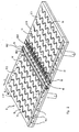
- the table 2 consists essentially of a table top 2.1, which forms an upwardly facing support surface. It comprises two segments, which are formed as two equal rectangular halves 2.11 and 2.12. The upper sides 17.1 and 17.2 of the segments 2.11, 2.12 each form a surface portion of the support surface of the table 2, which faces the disk-shaped workpiece 5, and have on its surface manifold outlets 15 from which pressurized air flows out, and numerous exhaust ports 14, over the Pressurized air from the Upper sides 17.1, 17.2 of the plate halves 2.11 and 2.12 is at least partially sucked.
- the discharge openings 14 are formed on the upper side 17.2 of the plate half 2.12 and on the upper side 17.1 of the plate half 2.11 as open at the top grooves, depressions or channels, which in plan view in each case a zigzag or snake-shaped withdrawal cross-section substantially over the entire width B. of the table top halves 2.12 or 2.11 without interruption. So are in Fig. 2 six discharge openings 14 are shown with the same shape, which are seen in the feed direction of the workpiece 5, so seen in the longitudinal direction L of the table 2, equidistant behind the other.
- the table half 2.11 has six equidistant behind each other, serpentine discharge openings 14.
- the discharge openings 14 are distributed substantially uniformly over the entire top 17.1 and 17.2 of the table top halves 2.12 and 2.11 so that a uniform removal of the gaseous medium on the table top surface away are ensured can.
- discharge openings 15 and outlet nozzles are formed with a circular outlet cross section equidistant behind each other in the longitudinal direction L as well as in the width direction B of the table top 2.1 seen.
- Their diameter is preferably between 0.1 mm and 2 mm, but may be between 0.05 mm and 10 mm, depending on the application.
- the outflow openings 15 are in Fig.
- a gap 16 or free space is provided, which extends over the entire width of the table 2 by way of example.
- a square 18 of the table 2 is inserted, the top of which is flush with the top 17.2 of the tabletop half 2.12, i.e., the top of the square 18 is coplanar with the top 17.2 of the tabletop half 2.12.
- a further square 19 is inserted into the gap 16 at a distance, the top of which extends flush with the top 17.1 of the tabletop half 2.11, i. whose top is coplanar with the top 17.1 of the table top half 2.11.
- Two rows of outflow openings 18.1 are formed on the upper side of the square 18, wherein the outflow openings 18.1 per row are formed equidistantly in succession over the entire width of the table top 2.1 or the length of the square 18.
- the two rows of outflow openings 18.1 are provided at a distance from one another and parallel to one another.
- a number of outlet openings 18.2 is distributed over the entire length of the square 18, wherein the individual outlet openings 18.2 are in turn arranged equidistantly in succession.
- two outflow openings are thus respectively arranged approximately on an imaginary center line between these two exhaust ports 18.2.
- each two outflow openings 18.1 thus not on a common, imaginary line with the adjacent exhaust port 18.2, but the outflow 18.1 are offset from the exhaust ports 18.2.
- the exhaust ports 18.2 and 18.1 Ausströmö réelleen the square 18 are evenly distributed over the top.
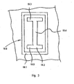
- the square 19 has on its upper side a plurality of opening groups 19.6 (see. Fig. 3 ), which are arranged in a row equidistant successively over the entire width B of the table 2 or along the entire length of the square 19.
- Each opening group 19.6 has a discharge opening 19.2 and an outflow opening 19.1, which surrounds the discharge opening 19.2 frame-shaped or annular.
- the vent opening 19.2 has a longitudinal section 19.4 extending in the longitudinal direction of the square 19 and two transverse sections 19.5 and 19.3 which continuously adjoin the ends of the longitudinal section 19.4 and extend transversely to the longitudinal section 19.4.
- the discharge opening 19.2 thus has a double-T-shaped withdrawal cross section on the surface or upper side of the square 19.
- the discharge opening 19.1 has an outlet cross-section in the form of a rectangular frame which frames the double-T-shaped discharge opening 19.2 throughout.
- eleven of these opening groups 19.6 formed in series.
- the two embodiments shown and arrangements of the openings at the four edges 18, 19 are alternatives that correspond to preferred embodiments. Above all, they permit a slight sliding of the workpiece onto the surface section which follows the gap 16 in the direction of displacement.
- two identically formed square edges 18, 19 are used, but this does not have to be the case.
- All exhaust ports 14, 18.2 and 19.2 are fluid-continuous with a vent line network 13, e.g. via the discharge nozzle 14.1 and in the tabletop halves 2.11 and 2.12 trained channels that are only hinted reproduced in the drawings coupled.
- the drain line network 13 is in turn fluidly coupled to the draining device 11, which may be e.g. may be a diaphragm pump or water jet pump, and the gas or air from the top of the table top 2.1 and the square edge 18 and 19 deducted.
- a vacuum control valve 12 is arranged fluid-throughly, e.g. can be controlled by means of a microprocessor device and software and appropriate electronics.
- the outflow openings 15, 18.1 and 19.1 are connected to a pressure line network 8, e.g. are fluidly coupled via corresponding conduit stubs and inner channels in the tabletop halves 2.11 and 2.12 and in the square edges 18 and 19, the pressure line network 8 in turn being fluidly coupled to a pressure generating device 6, e.g. is designed as a compressor that provides the pressurized air on the output side.
- a pressure regulating valve 7 is installed throughout the fluid, which can be electronically controlled, again via e.g. a microprocessor device. As a result, pressures between 0.1 bar and 1.5 bar are set above the ambient pressure.
- the laser device comprises, for example, two laser units 3, 9 which emit a laser beam in the direction of the upper side of the table 2 or the table top 2.1 for processing an upper side of the disk-shaped workpiece 5 or one Laser beam toward the bottom of the disk-shaped workpiece 5 within the gap 16 between the table top halves 2.12 and 2.11 radiates to edit the bottom of the disk-shaped workpiece 5 with laser beams can.
- the first laser beam (cf. Fig. 1 ) passes from the laser unit 3 coming a focusing device 4, which focuses the laser beam on the top of the disc-shaped workpiece 5, while the second laser beam from the further laser unit 9 coming from a focusing device 10 passes, the laser beam on the underside of the disc-shaped workpiece 5 for processing focused.
- the disk-shaped workpiece 5 can thus be processed both on its underside and on its upper side simultaneously with the preferred embodiment of the device.
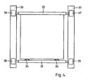
- the feed of the disk-shaped workpiece 5 in the longitudinal direction L of the table 2 is by means of a feed device ( Fig. 4 ). It comprises a linear guide with two rails 30, 31 attached to edge strips 21, which are arranged on the opposite side edges of the segments 2.11, 2.12 of the table 1, which run transversely across the gap 16. They can be designed as semi-circular profiles, for example.
- a receptacle for the workpiece 5 is guided, which consists of two longitudinally spaced independently displaceable brackets 32, 33.
- the first holder 32 has longitudinally acting stops for the edge of the workpiece, which allow to accurately position it in the receptacle, while the second holder 33 carries a pressing device, which consists for example of two arcuate steel springs 34, 35 or pneumatically actuated cylinders and presses the workpiece 5 against the stops.
- a pressing device which consists for example of two arcuate steel springs 34, 35 or pneumatically actuated cylinders and presses the workpiece 5 against the stops.
- Each of the two brackets 32, 33 is on both sides in the rails 30, 31 out.
- a drive device comprising linear motors 36, 37 and 38, 39, each with wheels tuned to the rails 30, 31, respectively driving the first holder 32 and the second holder 33, serves to engage the receiver in a precisely controllable manner with the workpiece 5 to slide over the gap 16 so that it can be processed successively by the laser beams 3, 9.
- the first holder 32 also has, for example, a pneumatic element for height adjustment, which makes it possible to adjust stops for supporting the workpiece in height.
- a pneumatic element for height adjustment which makes it possible to adjust stops for supporting the workpiece in height.
- the front edge of the workpiece 5 can be adjusted to a certain desired height.
- the remainder of the workpiece 5 is then adjusted to the same level by controlling the air cushion by means of the pressure regulating valves 7, 12.
- the workpiece 5 is contacted by the second holder 33 and pressed pressed regulated and thus fixed.
- a one-piece height-adjustable frame may be provided, on which the workpiece is placed.
- the laser beam emitted by the laser unit 3 or 9, together with the respectively associated focusing devices 4 and 10, respectively, can be moved across the width B of the table 2 or the workpiece 5 by means of a deflection device, e.g. a galvanomirror or a movable deflecting mirror, be distracted.
- a deflection device e.g. a galvanomirror or a movable deflecting mirror
- the feed or the leadership of the disc-shaped workpiece can be designed without contact, z. B. by appropriate control of the air flow or by laterally mounted additional Gaseinströmö réelleen. If the surface of the disk-shaped workpiece 5 to be processed, the pressure generating device 6 and the discharge device 11 are put into operation, whereby the pressure generating means 6 pressurized air through the pressure control valve 7 and the pressure line network 8 the outflow openings 15 of the two tabletop halves / segments 2.11 and 2.12 and the outflow openings 18.1 of the square 18 and the outflow openings 19.1 of the square 19 supplies. The pressurized air flows out of the discharge ports at the top of the table top halves 2.11 and 2.12 and the four-edge 18 and 19 at high pressure.
- the disk-shaped workpiece 5 is then placed on the table 2 and coupled as described with the feed device.
- the disk-shaped workpiece 5 is held raised above the top or surface of the table 2 by the generated air cushion.
- This storage of the disk-shaped workpiece 5 by air cushion is done uniformly over the entire table top or table surface, since the outflow openings 15 and the discharge openings 14 are evenly distributed up to the gap area. Since the disk-shaped workpiece 5 is thus mounted on an air cushion or a gas flow between the underside of the disk-shaped workpiece 5 and the tops 17.1 and 17.2 of the table 2, it can not come into contact with the top of the table 2.
- the pressure of the air flow at the top of the table 2 on the pressure difference between the supply side and the discharge side can be adjusted so that the disk-shaped workpiece 5 safely and quietly at a predetermined height, which corresponds to the machining height of the disk-shaped workpiece 5, is mounted on the generated air cushion between the disk-shaped workpiece 5 and the top of the table 2.
- the distance of the workpiece from the support surface can be adjusted approximately to a value between 0.01 mm and 1 mm, preferably between 0.05 mm and 0.3 mm.
- the precise adjustment of this processing height is especially important when the processing device is a laser device, since in this case the workpiece, or the area to be processed in the focus of the laser must be maintained.
- the height of the workpiece 5 can also be checked once by providing a measuring device with suitable measuring means which determine the height, for example interferometrically or by triangulation methods, and are arranged distributed in the gap 16 or over the table.
- suitable measuring means which determine the height, for example interferometrically or by triangulation methods, and are arranged distributed in the gap 16 or over the table.
- the workpiece 5 can be traversed once over the gap 16 and its uniform altitude be checked over, in the latter case, the review can be done quickly through the distributed measuring means.
- the height of the workpiece 5 can also be kept constant during processing by feedback.
- the workpiece 5 can be positioned with the aid of the measuring device over the gap with an accuracy of 50 .mu.m to 100 .mu.m, wherein the height of the workpiece measured by the measuring device with an accuracy of 1 .mu.m and then via a suitable control circuit by means of the pressure valves 7, 12th the gas pressure is regulated.
- the focus of the laser can also be controlled.
- various workpiece machining operations can be carried out while simultaneously machining the lower side and also the upper side of the workpiece 5.
- material can be removed from the top or bottom of the workpiece 5 with the laser beam to produce e.g. To be able to form conductor tracks on the workpiece, or the workpiece can be laser marked or scratched.
- a coating on the top side it is also possible for a coating on the top side to be processed through the workpiece 5 from the underside.
- a special case of material removal is the so-called "laser scribing", in which certain areas are to be electrically insulated on a flat, continuously conductive coated thin substrate.
- the conductive layer is selectively removed by means of a laser along a line (the method is known as laser ablation) and thus the adjacent surfaces are electrically insulated.
- the workpiece is mounted without contact on a table according to the invention on the gas or air cushion, reciprocated in the longitudinal direction L of the table 2 over the treatment device (laser) provided between the segments 2.11 and 2.12 in the gap 16.
- the movement in the transverse direction of the table can be achieved by the movement of the treatment device in the gap 16, in combination with the longitudinal movement can be described in a known manner lines on the substrate.
- markings on the workpiece which allow the positioning of the workpiece relative to the table or to the treatment device. These markings are advantageously carried out as crosses or orientation lines.
- the application the markings can be done in an upstream process, for. B. by printing or in a photolithographic exposure process.
- the marking can also be done with the inventive device via laser, z. B. in a first operation.
- a detector for the markings eg a pattern recognition device as measuring device. This can be done stationary in several places in or on the table, which allows to monitor several markers at the same time.
- the measuring device can also be provided in or above the gap 16, preferably on a moving device such as the processing device (laser) or even combined with it.
- the positional control over the markings also makes it possible to design the feed and guide devices in such a way that the precision of the positioning does not have to be ensured by them. This will be necessary in particular when the bearing and guide are non-contact or largely non-contact.
- the markings are also important if the substrate must be described several times, for. B. between different coating processes, each store the layers of material on the workpiece. It can thus be ensured that the orientation of the workpiece is recognized and the lines to be rewritten follow a predetermined pattern.
- the accuracy requirements are in such cases at 5 to 500 microns. However, accuracies of 10 ⁇ m are easily achievable when markers are restarted, especially since the control of the movement of the workpiece can still meet much higher accuracies requirements and can be for example 1 micron.
- the specified accuracies apply in each case for positioning transversely to the gap as well as parallel to the gap.
- the markers in the form of z. B. a bar code also serve to identify the workpiece.
- an individual description pattern per workpiece can be provided and the unique identification of the workpiece on the marking is guaranteed. If, in addition to a processing device, measuring and testing devices are also provided, the device thus also makes it possible to unambiguously allocate the device under test and the measured data.
- the device according to the invention can also be used for separating or cutting disk-shaped workpieces, for example glass plates or ceramic plates.
- the laser-induced cutting of plates can be used.
- the apparatus of the invention cuts the plate 5 by moving the laser beam along a cutting line, whereby the glass plate is heated along the cutting line but not melted.
- the heating of the plate along the cutting line is followed by cooling along the cutting line by a cooling medium, eg a cooled jet of air, which creates stresses along the cutting line in the plate resulting in a precise break of the glass sheet along the cutting line.
- the table may also have several consecutive gaps, e.g. are separated by four-edge and in each of which a processing device is arranged. This allows several processing operations to take place simultaneously.
Landscapes
- Engineering & Computer Science (AREA)
- Physics & Mathematics (AREA)
- Chemical & Material Sciences (AREA)
- Optics & Photonics (AREA)
- Mechanical Engineering (AREA)
- Materials Engineering (AREA)
- Organic Chemistry (AREA)
- Plasma & Fusion (AREA)
- Health & Medical Sciences (AREA)
- Toxicology (AREA)
- Thermal Sciences (AREA)
- Laser Beam Processing (AREA)
- Electrical Discharge Machining, Electrochemical Machining, And Combined Machining (AREA)
- Re-Forming, After-Treatment, Cutting And Transporting Of Glass Products (AREA)
- Jigs For Machine Tools (AREA)
- Drying Of Semiconductors (AREA)
- Container, Conveyance, Adherence, Positioning, Of Wafer (AREA)
- Multi-Process Working Machines And Systems (AREA)
- Polishing Bodies And Polishing Tools (AREA)
- Machine Tool Units (AREA)
Abstract
Description
Die Erfindung betrifft einen Tisch zur Aufnahme eines Werkstücks gemäss dem Oberbegriff des Anspruchs 1 sowie ein Verfahren zur Bearbeitung eines Werkstücks auf einem erfindungsgemässen Tisch. Derartige Tische werden z.B. für die Bearbeitung von plattenförmigen Werkstücken wie Glasplatten mittels Lasern, z.B. zum Laserscriben oder Schneiden eingesetzt.The invention relates to a table for holding a workpiece according to the preamble of claim 1 and a method for machining a workpiece on a table according to the invention. Such tables are e.g. for the processing of plate-shaped workpieces such as glass plates by means of lasers, e.g. used for laser scrubbing or cutting.
Es ist bekannt, Glasplatten und ähnliche Werkstücke an zwei gegenüberliegenden Rändern einzuspannen und, gewöhnlich von oben, zu bearbeiten. Bei grossflächigen dünnen Werkstücken entsteht dabei jedoch stets ein Durchhang, der den Abstand zwischen Werkstück und Bearbeitungsvorrichtung in nicht völlig kontrollierbarer Weise beeinflusst, was bei hohen Genauigkeitsanforderungen mindestens weitere Vorkehrungen erforderlich macht, u.U. aber auch eine ausreichende Präzision bei der Bearbeitung nicht zulässt.It is known to clamp glass plates and similar workpieces on two opposite edges and, usually from above, to machine. In large-scale thin workpieces, however, there is always a sag that affects the distance between the workpiece and processing device in a not completely controllable manner, which makes at least further precautions required for high accuracy requirements u.U. but also does not allow sufficient precision in the processing.
Demgegenüber ist es möglich, das Werkstück auf eine durchgehende ebene Stützfläche aufzulegen und so Durchhang weitgehend zu verhindern. Wegen der unvermeidlichen Rauhigkeit der Stützfläche können jedoch lokale Deformationen des Werkstücks, die zwar wesentlich geringfügiger, aber z.B. bei der Herstellung von Strukturen im Mikrometer- und Submikrometerbereich immer noch störend sind, auch in diesem Fall nicht vollständig ausgeschlossen werden. Ausserdem besteht ein nicht zu vernachlässigendes Risiko, dass das Werkstück durch den direkten Kontakt mit der Stützfläche verkratzt oder seine Oberfläche auf andere Weise beschädigt wird. Dies kann vor allem bei der Bearbeitung von Substraten für die Halbleiterindustrie wie grossflächigen Wafern zu Ausschuss führen. Es wurde daher schon vorgeschlagen, Tische zur Aufnahme von Werkstücken mit Ausströmöffnungen zur Herstellung eines Gaspolsters zu versehen.In contrast, it is possible to hang the workpiece on a continuous planar support surface and thus largely prevent sag. Because of the unavoidable roughness of the support surface, however, local deformations of the workpiece, although much smaller, but still for example in the production of structures in the micrometer and Submikrometerbereich still disturbing even in this case are not completely excluded. In addition, there is a significant risk that the workpiece will be scratched or otherwise damaged by direct contact with the support surface. This can lead to rejects, especially when processing substrates for the semiconductor industry such as large-area wafers. It has therefore already been proposed to provide tables for receiving workpieces with outflow openings for producing a gas cushion.
So ist aus
Der Erfindung liegt die Aufgabe zu Grunde, einen Tisch anzugeben, der eine hochgenaue Bearbeitung des Werkstücks durch Laser oder anderer Bearbeitungsvorrichtungen ermöglicht. Diese Aufgabe wird durch die Merkmale im Kennzeichen des Anspruchs 1 gelöst. Ausserdem soll ein geeignetes Verfahren zur Bearbeitung eines Werkstücks auf einem erfindungsgemässen Tisch angegeben werden. Diese Aufgabe wird durch die Merkmale des Anspruchs 15 gelöst.The invention has for its object to provide a table that allows high-precision machining of the workpiece by laser or other processing devices. This object is solved by the features in the characterizing part of claim 1. In addition, a suitable method for machining a workpiece on a table according to the invention is to be specified. This object is solved by the features of
Die Aufnahme ermöglicht eine präzise lineare Bewegung von Werkstücken verschiedener Längen längs einer konstanten Vorschubrichtung und damit eine entsprechend genaue Bearbeitung. Damit können etwa Muster mit einer Laser-Bearbeitungsvorrichtung erzeugt werden, obwohl dies eine Genauigkeit bis hinab zu einigen Mikrometern erfordern kann.The recording allows a precise linear movement of workpieces of different lengths along a constant feed direction and thus a correspondingly accurate machining. This can be used to produce patterns with a laser processing device, although this may require accuracy down to a few microns.
Durch die Luftkissenlagerung des Werkstücks, der Platte bzw. der Glasplatte hat die vorliegende Erfindung den grossen Vorteil, dass beim Bearbeiten des plattenförmigen Werkstücks dessen Unterseite nicht mit der Tischoberseite in Berührung kommt, wodurch eine unerwünschte Verschmutzung bzw. ein Verkratzen oder eine Beschädigung der Plattenunterseite, z.B. durch die Tischoberfläche oder Partikel vermieden wird. Ferner kann durch die Luftkissenlagerung des Werkstücks ein Durchhängen oder Durchbiegen des Substrats vermieden werden. Durch Einstellen der Druckverhältnisse kann darüber das Höhenniveau in gewissen Grenzen geregelt werden, was bei manchen der Behandlungsschritte von Vorteil ist. Darüber hinaus ermöglicht das beschriebene Luft- oder Gaskissen einen (quasi-)reibungsfreien Transport des Werkstückes auf der Tischplatte.By the Luftkissenlagerung of the workpiece, the plate or the glass plate, the present invention has the great advantage that when editing the plate-shaped workpiece whose bottom does not come into contact with the table top, creating an undesirable contamination or scratching or damage to the underside of the plate, Eg by the table surface or particles is avoided. Furthermore, sagging or bending of the substrate can be avoided by the air cushion bearing of the workpiece. By adjusting the pressure conditions over the height level can be regulated within certain limits, which is advantageous in some of the treatment steps. Furthermore allows the described air or gas cushion a (quasi) frictionless transport of the workpiece on the table top.
Als Werkstücke sind hier insbesondere scheibenförmige oder plattenförmige Werkstücke, z.B. Glasscheiben, Glassubstrate, Keramikplatten, Wafer aus Halbleitermaterial wie Silizium in Betracht zu ziehen. Diese Platten können Flächen von z.B. 2 m2 und darüber erreichen und gleichzeitig eine Stärke von z.B. nur 1 mm und kleiner haben, also großflächig und dünn sein, und sie bestehen in der Regel aus einem spröden Material wie Glas oder Keramik.As workpieces are here in particular disc-shaped or plate-shaped workpieces, such as glass, glass substrates, ceramic plates, wafers made of semiconductor material such as silicon into consideration. These plates can reach areas of, for example, 2 m 2 and above and at the same time have a thickness of, for example, only 1 mm and smaller, ie be large-area and thin, and they usually consist of a brittle material, such as glass or ceramic.
Bevorzugt hat die Vorrichtung der Erfindung einen Tisch oder eine Tischplatte, die aus mindestens zwei Segmenten aufgebaut ist. Die dem Werkstück zugewandte Oberfläche eines Segmentes weist mehrere äquidistant zueinander sich erstreckende und in Reihen angeordnete Austrittsöffnungen bzw. Austrittskanäle auf für das druckbeaufschlagte Gas von der Druckeinrichtung, die mit der Druckeinrichtung fluidgängig gekoppelt sind. Die Austrittsöffnungen des druckbeaufschlagten Gases sind über im wesentlichen die gesamte Tischoberseite gleichmäßig verteilt, wodurch ein gleichmäßiger Druck auf das luftkissengelagerte Werkstück erzeugt wird und somit ein unerwünschtes Durchbiegen der Werkstückplatte vermieden wird.Preferably, the device of the invention has a table or a table top, which is composed of at least two segments. The workpiece-facing surface of a segment has a plurality of equidistantly extending and arranged in rows outlet openings or outlet channels for the pressurized gas from the printing device, which are fluidly coupled to the printing device. The outlet openings of the pressurized gas are evenly distributed over substantially the entire top of the table, whereby a uniform pressure is generated on the air-cushioned workpiece and thus an undesirable bending of the workpiece plate is avoided.
Die Vorrichtung der Erfindung hat bevorzugt eine Saugeinrichtung zum Ansaugen des druckbeaufschlagten Gases von der dem Werkstück zugewandten Oberseite des Tisches oder der Tischplatte. Dies hat den Vorteil, dass über die Druckdifferenz zwischen der Druckseite mit hohem Druck und der Ansaugseite mit zumindest kleinerem Druck der herrschende Fluiddruck im tragenden Gaskissen kontrolliert eingestellt werden kann. Hierdurch kann der Druck im Gaskissen bzw. Luftkissen auch derart eingestellt werden, dass das scheibenförmige Werkstück die vorgegebene Bearbeitungshöhe für die Bearbeitung einhält.The apparatus of the invention preferably has suction means for sucking the pressurized gas from the top of the table or table top facing the workpiece. This has the advantage that controls the prevailing fluid pressure in the supporting gas cushion on the pressure difference between the pressure side with high pressure and the suction side with at least a smaller pressure can be adjusted. In this way, the pressure in the gas cushion or air cushion can also be adjusted such that the disk-shaped workpiece complies with the specified processing height for the machining.
Bevorzugt hat der Tisch (bzw. sinngleich angewandt ein Segment) an seiner dem Werkstück zugewandten Oberfläche mehrere über die Oberseite des Tisches oder der Tischplatte hinweg gleichmäßig verteilte Ansaugöffnungen, die mit der Ansaugeinrichtung fluidgängig gekoppelt sind. Hierdurch wird eine gleichmäßiges Ansaugen über die gesamte Tisch- bzw. Segmentoberseite gesehen ermöglicht und somit auch eine gleichmäßig über die gesamte Tisch- bzw. Segmentfläche verteilte und auftretende Druckverteilung auf das Werkstück erreicht. Der Tisch der Erfindung hat bevorzugt in oder an seiner dem Werkstück zugewandten Oberseite mehrere äquidistant aufeinanderfolgend in Längsrichtung des Tisches sich erstreckende Ansaugkanäle, Ansaugrillen oder Vertiefungen als Ansaugöffnungen, die sich - bevorzugt - jeweils im wesentlichen über die gesamte Breite des Tisches ununterbrochen erstrecken, wodurch die gleichmäßig auf die Fläche bezogene Ansaugung von Fluid oder Luft verbessert wird.Preferably, the table (or equivalent applied a segment) has on its surface facing the workpiece a plurality of uniformly distributed over the top of the table or the table top across suction, which are fluidly coupled to the suction. As a result, a uniform suction over the entire table or segment top view is possible and thus also a uniform over the entire table or segment surface distributed and occurring pressure distribution reaches the workpiece. The table of the invention preferably in or on its upper side facing the workpiece a plurality of equidistantly successive in the longitudinal direction of the table extending intake ducts, Ansaugrillen or depressions as suction, which - preferably - each extend substantially over the entire width of the table without interruption, whereby the uniform suction on the surface of fluid or air is improved.
Die Ansaugkanäle können einen schlangenförmigen, zickzackförmigen, sägezahnförmigen und/oder mäanderförmigen Ansaugquerschnitt haben. Der Ansaugquerschnitt der Ansaugöffnung kann jedoch auch rund, z.B. kreisförmig, oder eckig, z.B. rechteckig, sein.The intake ducts can have a serpentine, zigzag-shaped, sawtooth-shaped and / or meander-shaped intake cross-section. However, the suction cross-section of the suction port may also be round, e.g. circular, or angular, e.g. rectangular, be.
Bevorzugt ist der Tisch bzw. die Tischplatte des Tisches derart unterteilt, dass Segmente (entsprechend) Tischplattenhälften koplanar, stirnseitig unter Ausbildung eines Spaltes, einer Vertiefung bzw. eines Zwischenraums zwischen den Segmenten bereitgestellt sind. Im Spalt ist eine Behandlungsvorrichtung anbringbar, die je nach Aufgabe der Vorrichtung eine Mess, Prüf- oder Bearbeitungsvorrichtung sein kann. Auch kann oberhalb des Tisches, über dem Substrat eine weitere Bearbeitungsvorrichtung angebracht werden, räumlich versetzt oder aber in einer Anordnung, die ein gleichzeitiges Behandeln desselben Substratgebietes von oben und unten erlaubt. Dies kann wiederum, je nach Zweckbestimmung gleichzeitiges Bearbeiten, aber auch Bearbeiten und Messen sein, was z. B. eine Regelung des Bearbeitungsvorgangs erlaubt.Preferably, the table or the table top of the table is subdivided such that segments (correspondingly) table top halves coplanar, frontally to form a gap, a recess or a gap are provided between the segments. In the gap, a treatment device can be attached, which may be a measuring, testing or processing device depending on the task of the device. Also, above the table, another processing device can be mounted over the substrate, spatially offset or in an arrangement that allows simultaneous treatment of the same substrate area from above and below. This in turn, depending on the purpose of simultaneous editing, but also editing and measuring be what z. B. allows a regulation of the machining process.
So wird beispielsweise im Fall von Laserbearbeitung durch den Spalt zwischen den Segmenten vorteilhaft eine gleichzeitige, beidseitige Bearbeitung von Platten mittels Laserstrahlung ermöglicht.For example, in the case of laser processing through the gap between the segments, a simultaneous, two-sided processing of plates by means of laser radiation is advantageously made possible.
Im folgenden wird die Erfindung anhand von Figuren, welche lediglich ein Ausführungsbeispiel darstellen, näher erläutert. Es zeigen
- Fig. 1
- eine schematische Ansicht einer beispielhaften Ausführungsform des erfindungsgemässen Tischs,
- Fig. 2
- eine perspektivische Ansicht, die den Tisch der Ausführungsform der Vorrichtung der Erfindung von
Fig. 1 herausgetrennt zeigt, - Fig. 3
- eine Draufsicht auf eine ausgeschnittene Öffnungsgruppe, die in der Ausführungsform der Vorrichtung der Erfindung in
Fig. 2 verwendet wird und - Fig. 4
- eine Draufsicht auf eine Aufnahme für ein Werkstück und eine Linearführung für dieselbe an der Oberseite des erfindungsgemässen Tisches.
- Fig. 1
- a schematic view of an exemplary embodiment of the inventive table,
- Fig. 2
- a perspective view of the table of the embodiment of the device of the invention of
Fig. 1 cut out shows - Fig. 3
- a plan view of a cut-out opening group, which in the embodiment of the Device of the invention in
Fig. 2 is used and - Fig. 4
- a plan view of a receptacle for a workpiece and a linear guide for the same at the top of the inventive table.
In
Der Tisch 2 besteht im wesentlichen aus einer Tischplatte 2.1, die eine nach oben weisende Stützfläche bildet. Sie umfasst zwei Segmente, die als zwei gleich große rechteckige Hälften 2.11 und 2.12 ausgebildet sind. Die Oberseiten 17.1 und 17.2 der Segmente 2.11, 2.12 bilden jeweils einen Flächenabschnitt der Stützfläche des Tisches 2, der dem scheibenförmigen Werkstück 5 zugewandt ist, und haben an ihrer Oberfläche vielzählige Ausströmöffnungen 15, aus denen druckbeaufschlagte Luft ausströmt, und vielzählige Abzugsöffnungen 14, über die druckbeaufschlagte Luft von den Oberseiten 17.1, 17.2 der Plattenhälften 2.11 und 2.12 zumindest teilweise angesaugt wird.The table 2 consists essentially of a table top 2.1, which forms an upwardly facing support surface. It comprises two segments, which are formed as two equal rectangular halves 2.11 and 2.12. The upper sides 17.1 and 17.2 of the segments 2.11, 2.12 each form a surface portion of the support surface of the table 2, which faces the disk-shaped
Die Abzugsöffnungen 14 sind an der Oberseite 17.2 der Plattenhälfte 2.12 und an der Oberseite 17.1 der Plattenhälfte 2.11 als an der Oberseite offene Rillen, Vertiefungen bzw. Kanäle ausgebildet, die in der Draufsicht jeweils einen zickzack- oder schlangenförmigen Abzugquerschnitt im wesentlichen über die gesamte Breite B der Tischplattenhälften 2.12 bzw. 2.11 ununterbrochen haben. So sind in
Zwischen den beiden Segmenten 2.11 und 2.12 ist ein Spalt 16 oder Freiraum vorgesehen, der sich beispielhaft über die gesamte Breite des Tisches 2 erstreckt. Zwischen dem Spalt 16 und der Tischplattenhälfte 2.12 ist ein Vierkant 18 des Tisches 2 eingesetzt, dessen Oberseite bündig zur Oberseite 17.2 der Tischplattenhälfte 2.12 verläuft, d.h., die Oberseite des Vierkants 18 ist koplanar eben zur Oberseite 17.2 der Tischplattenhälfte 2.12. Gegenüberliegend zum Vierkant 18 ist mit Abstand dazu ein weiterer Vierkant 19 in den Spalt 16 eingesetzt, dessen Oberseite sich bündig mit der Oberseite 17.1 der Tischplattenhälfte 2.11 erstreckt, d.h. dessen Oberseite koplanar zur Oberseite 17.1 der Tischplattenhälfte 2.11 ist.Between the two segments 2.11 and 2.12, a
An der Oberseite des Vierkants 18 sind zwei Reihen von Ausströmöffnungen 18.1 ausgebildet, wobei die Ausströmöffnungen 18.1 pro Reihe äquidistant aufeinanderfolgend über die gesamte Breite der Tischplatte 2.1 bzw. der Länge des Vierkants 18 ausgebildet sind. In der Längsrichtung L gesehen sind die beiden Reihen von Ausströmöffnungen 18.1 mit Abstand zueinander und parallel zueinander vorgesehen. Zwischen den beiden Reihen mit Ausströmöffnungen 18.1 ist eine Reihe von Abzugsöffnungen 18.2 über die gesamte Länge des Vierkants 18 verteilt, wobei die einzelnen Abzugsöffnungen 18.2 wiederum äquidistant aufeinanderfolgend angeordnet sind. Im Bereich zwischen jeweils zwei Abzugsöffnungen 18.2 sind somit jeweils zwei Ausströmöffnungen etwa auf einer gedachten Mittenlinie zwischen diesen jeweils zwei Abzugsöffnungen 18.2 angeordnet. In der Längsrichtung L der Tischplatte 2.1 gesehen, liegen die jeweils zwei Ausströmöffnungen 18.1 somit nicht auf einer gemeinsamen, gedachten Linie mit der benachbarten Abzugsöffnung 18.2, sondern die Ausströmöffnungen 18.1 sind versetzt zu den Abzugsöffnungen 18.2. Die Abzugsöffnungen 18.2 und Ausströmöffnungen 18.1 des Vierkants 18 sind über dessen Oberseite gleichmäßig verteilt.Two rows of outflow openings 18.1 are formed on the upper side of the square 18, wherein the outflow openings 18.1 per row are formed equidistantly in succession over the entire width of the table top 2.1 or the length of the square 18. As seen in the longitudinal direction L, the two rows of outflow openings 18.1 are provided at a distance from one another and parallel to one another. Between the two rows with outflow openings 18.1, a number of outlet openings 18.2 is distributed over the entire length of the square 18, wherein the individual outlet openings 18.2 are in turn arranged equidistantly in succession. In the area between in each case two exhaust ports 18.2, two outflow openings are thus respectively arranged approximately on an imaginary center line between these two exhaust ports 18.2. Seen in the longitudinal direction L of the table top 2.1, are each two outflow openings 18.1 thus not on a common, imaginary line with the adjacent exhaust port 18.2, but the outflow 18.1 are offset from the exhaust ports 18.2. The exhaust ports 18.2 and 18.1 Ausströmöffnungen the square 18 are evenly distributed over the top.
Der Vierkant 19 hat an seiner Oberseite eine Vielzahl von Öffnungsgruppen 19.6 (vgl.
Sämtliche Abzugsöffnungen 14, 18.2 und 19.2 sind fluiddurchgängig mit einem Abzugleitungsnetzwerk 13 z.B. über die Abzugstutzen 14.1 und in den Tischplattenhälften 2.11 und 2.12 ausgebildete Kanäle, die in den Zeichnungen nur andeutungsweise wiedergegeben sind, gekoppelt. Das Abzugleitungsnetzwerk 13 ist wiederum mit der Abzugeinrichtung 11 fluiddurchgängig gekoppelt, die z.B. eine Membranpumpe oder Wasserstrahlpumpe sein kann, und die Gas bzw. Luft von der Oberseite der Tischplatte 2.1 und der Vierkante 18 und 19 abzieht. Zwischen dem Abzugleitungsnetzwerk 13 und der Abzugeinrichtung 11 ist ein Unterdruckregelventil 12 fluiddurchgängig angeordnet, das z.B. mittels einer Mikroprozessoreinrichtung und Software und entsprechender Elektronik gesteuert werden kann.All
Die Ausströmöffnungen 15, 18.1 und 19.1 sind mit einem Druckleitungsnetzwerk 8 z.B. über entsprechende Leitungsstutzen und innere Kanäle in den Tischplattenhälften 2.11 und 2.12 und in den Vierkanten 18 und 19 fluidgängig gekoppelt, wobei das Druckleitungsnetzwerk 8 wiederum mit einer Druckerzeugungseinrichtung 6 fluidgängig gekoppelt ist, die z.B. als Kompressor ausgelegt ist, der die druckbeaufschlagte Luft ausgangsseitig bereitstellt. Zwischen dem Druckleitungsnetzwerk 8 und der Druckerzeugungseinrichtung 6 ist ein Druckregelventil 7 fluiddurchgängig eingebaut, das elektronisch gesteuert bzw. geregelt werden kann, wiederum über z.B. eine Mikroprozessoreinrichtung. Dadurch werden Drücke zwischen 0.1 bar und 1.5 bar über dem Umgebungsdruck eingestellt.The
Die Lasereinrichtung umfasst z.B. zwei Lasereinheiten 3, 9, die einen Laserstrahl in Richtung der Oberseite des Tisches 2 bzw. der Tischplatte 2.1 zur Bearbeitung einer Oberseite des scheibenförmigen Werkstücks 5 abstrahlt bzw. einen Laserstrahl in Richtung zur Unterseite des scheibenförmigen Werkstücks 5 innerhalb des Spalts 16 zwischen den Tischplattenhälften 2.12 und 2.11 abstrahlt, um die Unterseite des scheibenförmigen Werkstücks 5 mit Laserstrahlen bearbeiten zu können. Der erste Laserstrahl (vgl.
Der Vorschub des scheibenförmigen Werkstücks 5 in der Längsrichtung L des Tisches 2 wird mittels einer Vorschubeinrichtung (
Der von der Lasereinheit 3 oder 9 ausgesandte Laserstrahl zusammen mit den jeweils zugeordneten Fokussiereinrichtungen 4 bzw. 10 kann über die Breite B des Tisches 2 bzw. des Werkstücks 5 mittels einer Ablenkeinrichtung, z.B. eines Galvanospiegels oder eines verfahrbaren Umlenkspiegels, abgelenkt werden. Während des Vorschubs ist das scheibenförmige Werkstück 5 an dessen Seitenrändern durch Randleisten 21 des Tisches 2 geführt.The laser beam emitted by the
Alternativ kann der Vorschub bzw. die Führung des scheibenförmigen Werkstücks berührungsfrei gestaltet werden, z. B. durch entsprechende Steuerung des Luftstroms bzw. durch seitlich angebrachte zusätzliche Gaseinströmöffnungen. Soll die Oberfläche des scheibenförmigen Werkstücks 5 bearbeitet werden, werden die Druckerzeugungseinrichtung 6 und die Abzugeinrichtung 11 in Betrieb gesetzt, wodurch die Druckerzeugungseinrichtung 6 druckbeaufschlagte Luft über das Druckregelventil 7 und das Druckleitungsnetzwerk 8 den Ausströmöffnungen 15 der beiden Tischplattenhälften / Segmenten 2.11 und 2.12 und den Ausströmöffnungen 18.1 des Vierkants 18 und den Ausströmöffnungen 19.1 des Vierkants 19 zuführt. Die druckbeaufschlagte Luft strömt aus den Ausströmöffnungen an der Oberseite der Tischplattenhälften 2.11 und 2.12 und der Vierkante 18 und 19 mit hohem Druck aus. Das scheibenförmige Werkstück 5 wird dann auf den Tisch 2 gelegt und wie beschrieben mit der Vorschubeinrichtung gekoppelt. Das scheibenförmige Werkstück 5 wird dabei über der Oberseite bzw. Oberfläche des Tisches 2 durch das erzeugte Luftkissen angehoben gehalten. Diese Lagerung des scheibenförmigen Werkstücks 5 per Luftkissen geschieht gleichmäßig über die gesamte Tischoberseite bzw. Tischfläche gesehen, da die Ausströmöffnungen 15 und die Abzugsöffnungen 14 bis auf den Spaltbereich gleichmäßig verteilt sind. Da das scheibenförmige Werkstück 5 somit auf einem Luftkissen bzw. einer Gasströmung zwischen der Unterseite des scheibenförmigen Werkstücks 5 und den Oberseiten 17.1 und 17.2 des Tisches 2 gelagert ist, kann es mit der Oberseite des Tisches 2 nicht in Berührung kommen.Alternatively, the feed or the leadership of the disc-shaped workpiece can be designed without contact, z. B. by appropriate control of the air flow or by laterally mounted additional Gaseinströmöffnungen. If the surface of the disk-shaped
Gleichzeitig wird über die Abzugsöffnungen 14, 18.2 und 19.2 an der Oberseite des Tisches 2 von der Abzugeinrichtung 11 über das Abzugleitungsnetzwerk 13 und das Unterdruckregelventil 12 abgezogen, wodurch der Druck der Luftströmung an der Oberseite des Tisches 2 über die Druckdifferenz zwischen der Zufuhrseite und der Abzugseite derart eingestellt werden kann, dass das scheibenförmige Werkstück 5 sicher und ruhig auf einer vorgegebenen Höhe, die der Bearbeitungshöhe des scheibenförmigen Werkstücks 5 entspricht, auf dem erzeugten Luftkissen zwischen dem scheibenförmigen Werkstück 5 und der Oberseite des Tisches 2 gelagert ist. Der Abstand des Werkstücks von der Stützfläche kann etwa auf einen zwischen 0,01 mm und 1 mm, vorzugsweise zwischen 0,05 mm und 0,3 mm liegenden Wert eingestellt werden. Die präzise Einstellung dieser Bearbeitungshöhe ist vor allem dann wichtig, wenn die Bearbeitungsvorrichtung eine Lasereinrichtung ist, da hierbei das Werkstück, bzw. der zu bearbeitende Bereich im Fokus des Lasers gehalten werden muss.At the same time is deducted through the
Oft genügt es, die Höhe des Werkstücks 5 ein Mal einzustellen und es wie weiter oben beschrieben zu fixieren.
Sie kann auch einmal überprüft werden, indem eine Messeinrichtung vorgesehen wird mit geeigneten Messmitteln, die die Höhe z.B. interferometrisch oder durch Triangulierverfahren bestimmen und im Spalt 16 oder über den Tisch verteilt angeordnet sind. Im ersteren Fall kann das Werkstück 5 ein Mal über den Spalt 16 verfahren und seine gleichmässige Höhenlage überpüft werden, im letzteren Fall kann die Ueberprüfung rasch durch die verteilten Messmittel erfolgen. Die Höhe des Werkstücks 5 kann auch während der Bearbeitung durch Rückkopplung konstant gehalten werden. Das Werkstück 5 kann mit Hilfe der Messeinrichtung über dem Spalt mit einer Genauigkeit von 50 µm bis 100 µm positioniert werden, wobei die Höhe des Werkstücks durch die Messeinrichtung mit einer Genauigkeit von 1 µm gemessen und danach über einen geeigneten Regelkreis mittels der Druckventile 7, 12 der Gasdruck geregelt wird. Zum Ausgleich kleiner Unebenheiten des Werkstücks 5 kann ausserdem der Fokus des Lasers geregelt werden.Often it is sufficient to adjust the height of the
It can also be checked once by providing a measuring device with suitable measuring means which determine the height, for example interferometrically or by triangulation methods, and are arranged distributed in the
Mit der Vorrichtung der Erfindung können verschiedene Werkstückbearbeitungen unter gleichzeitiger Bearbeitung der Unterseite und auch der Oberseite des Werkstücks 5 durchgeführt werden. Z.B. kann mit dem Laserstrahl Material von der Oberseite bzw. der Unterseite des Werkstücks 5 abgetragen werden, um z.B. Leiterbahnen auf dem Werkstück ausbilden zu können, oder das Werkstück kann mittels Laser markiert oder geritzt werden. Bei einem transparenten Werkstück 5 kann auch etwa eine Beschichtung an der Oberseite von der Unterseite her durch das Werkstück 5 hindurch bearbeitet werden.With the apparatus of the invention, various workpiece machining operations can be carried out while simultaneously machining the lower side and also the upper side of the
Ein Spezialfall des Materialabtrags ist das sogenannte "Laserscribing", bei dem auf einem flächig durchgängig leitend beschichteten dünnen Substrat bestimmte Bereiche elektrisch isoliert werden sollen. Hierzu wird mittels Laser die leitende Schicht entlang einer Linie gezielt abgetragen (die Methode ist als laserablation bekannt) und so die angrenzenden Flächen elektrisch isoliert. Hierzu wird das Werkstück auf einem erfindungsgemässen Tisch auf dem Gas- bzw. Luftpolster berührungsfrei gelagert, über der zwischen den Segmenten 2.11 und 2.12 im Spalt 16 vorgesehenen Behandlungsvorrichtung (Laser) in Längsrichtung L des Tisches 2 hin und herbewegt. Die Bewegung in Querrichtung des Tisches kann durch die Bewegung der Behandlungsvorrichtung im Spalt 16 erzielt werden, in Kombination mit der Längsbewegung lassen sich in bekannter Weise Linien auf dem Substrat beschreiben.A special case of material removal is the so-called "laser scribing", in which certain areas are to be electrically insulated on a flat, continuously conductive coated thin substrate. For this purpose, the conductive layer is selectively removed by means of a laser along a line (the method is known as laser ablation) and thus the adjacent surfaces are electrically insulated. For this purpose, the workpiece is mounted without contact on a table according to the invention on the gas or air cushion, reciprocated in the longitudinal direction L of the table 2 over the treatment device (laser) provided between the segments 2.11 and 2.12 in the
Häufig ist es notwendig, Markierungen auf dem Werkstück vorzusehen, die es erlauben, die Positionierung des Werkstücks relativ zum Tisch bzw. zur Behandlungsvorrichtung festzustellen. Diese Markierungen werden vorteilhaft als Kreuze oder Orientierungslinien ausgeführt. Das Aufbringen der Markierungen kann in einem vorgeschalteten Prozess erfolgen, z. B. durch Aufdrucken oder in einem photolithografischen Belichtungsprozess. Vorteilhaft kann das Markieren aber auch mit der erfindungsgemässen Vorrichtung via Laser erfolgen, z. B. in einem ersten Arbeitsvorgang. Dazu wird es besonders vorteilhaft sein, neben dem Laser als Bearbeitungsvorrichtung einen Detektor für die Markierungen, z.B. eine Mustererkennungsvorrichtung als Messvorrichtung vorzusehen. Dies kann ortsfest an mehreren Stellen im oder am Tisch erfolgen, was es erlaubt, mehrere Markierungen gleichzeitig zu überwachen. In einer Ausführungsform kann die Messvorrichtung aber auch im oder über dem Spalt 16 vorgesehen werden, bevorzugt auf einer Bewegungsvorrichtung wie die Bearbeitungsvorrichtung (Laser) oder sogar kombiniert mit diesem.It is often necessary to provide markings on the workpiece which allow the positioning of the workpiece relative to the table or to the treatment device. These markings are advantageously carried out as crosses or orientation lines. The application the markings can be done in an upstream process, for. B. by printing or in a photolithographic exposure process. Advantageously, the marking can also be done with the inventive device via laser, z. B. in a first operation. For this purpose, it will be particularly advantageous to provide, in addition to the laser as a processing device, a detector for the markings, eg a pattern recognition device as measuring device. This can be done stationary in several places in or on the table, which allows to monitor several markers at the same time. In one embodiment, however, the measuring device can also be provided in or above the
Die Positionskontrolle über die Markierungen gestattet es darüberhinaus, die Vorschub- und Führungsvorrichtungen so auszulegen, dass nicht durch sie die Präzision der Positionierung sichergestellt werden muss. Dies wird insbesondere dann notwendig sein, wenn die Lagerung und Führung berührungsfrei bzw. weitgehend berührungsfrei erfolgt.The positional control over the markings also makes it possible to design the feed and guide devices in such a way that the precision of the positioning does not have to be ensured by them. This will be necessary in particular when the bearing and guide are non-contact or largely non-contact.
Die Markierungen sind darüberhinaus wichtig, wenn das Substrat mehrfach beschrieben werden muss, z. B. zwischen verschiedenen Beschichtungsprozessen, die jeweils Lagen von Material auf dem Werkstück ablegen. So kann gewährleistet werden, dass die Orientierung des Werkstücks wiedererkannt wird und die neu zu schreibenden Linien einem vorgegebenen Muster folgt. Die Genauigkeitanforderungen liegen in solchen Fällen bei 5 bis 500 µm. Es Sind jedoch ohne weiteres Genauigkeiten von 10 µm beim Wiederanfahren von Markierungen erreichbar, zumal die Steuerung der Bewegung des Werkstücks noch wesentlich höheren Genauigkleitsanforderungen genügen kann und z.B. 1 µm betragen kann. Die angegebenen Genauigkeiten gelten jeweils für die Positionierung quer zum Spalt wie auch parallel zum Spalt.The markings are also important if the substrate must be described several times, for. B. between different coating processes, each store the layers of material on the workpiece. It can thus be ensured that the orientation of the workpiece is recognized and the lines to be rewritten follow a predetermined pattern. The accuracy requirements are in such cases at 5 to 500 microns. However, accuracies of 10 μm are easily achievable when markers are restarted, especially since the control of the movement of the workpiece can still meet much higher accuracies requirements and can be for example 1 micron. The specified accuracies apply in each case for positioning transversely to the gap as well as parallel to the gap.
Darüberhinaus können die Markierungen in Form z. B. eines Strichcodes auch dazu dienen, das Werkstück zu identifizieren. Somit kann ein individuelles Beschreibungsmuster pro Werkstück vorgesehen werden und die eindeutige Identifizierung des Werkstücks über die Markierung ist gewährleistet. Sind neben einer Bearbeitungsvorrichtung auch Mess- und Prüfvorrichtungen vorgesehen, erlaubt es die Vorrichtung somit auch Prüfling und Messdaten eindeutig zuzuordnen.In addition, the markers in the form of z. B. a bar code also serve to identify the workpiece. Thus, an individual description pattern per workpiece can be provided and the unique identification of the workpiece on the marking is guaranteed. If, in addition to a processing device, measuring and testing devices are also provided, the device thus also makes it possible to unambiguously allocate the device under test and the measured data.
In einer anderen Anwendung kann die erfindungsgemäße Vorrichtung auch zum Trennen bzw. Schneiden von scheibenförmigen Werkstücken, z.B. von Glasplatten oder Keramikplatten, verwendet werden. Hier kann das laserinduzierte Schneiden von Platten angewendet werden. Die Vorrichtung der Erfindung schneidet die Platte bzw. das Werkstück 5, indem der Laserstrahl entlang einer Schnittlinie verfahren wird, wobei die Glasplatte entlang der Schnittlinie erwärmt wird, aber nicht geschmolzen wird. Der Erwärmung der Platte entlang der Schnittlinie folgt eine Abkühlung entlang der Schnittlinie durch ein abkühlendes Medium, z.B. einen gekühlten Luftstrahl, wodurch Spannungen entlang der Schnittlinie in der Platte entstehen, die zu einem exakten Bruch der Glasplatte entlang der Schnittlinie führen. Durch die Luftkissenlagerung der Platte bzw. der Glasplatte der Vorrichtung der vorliegenden Erfindung kommt auch bei dem laserinduzierten Schneiden der Platte die Plattenunterseite nicht mit der Tischoberfläche in Berührung, wodurch eine unerwünschte Verschmutzung bzw. ein unerwünschtes Verkratzen oder ein Beschädigen der Plattenunterseite durch die Tischoberfläche vermieden wird.In another application, the device according to the invention can also be used for separating or cutting disk-shaped workpieces, for example glass plates or ceramic plates. Here, the laser-induced cutting of plates can be used. The apparatus of the invention cuts the
Der Tisch kann auch mehrere aufeinanderfolgende Spalte aufweisen, die z.B. durch Vierkante voneinander getrennt sind und in denen jeweils eine Bearbeitungsvorrichtung angeordnet ist. So können mehrere Bearbeitungsvorgänge gleichzeitig ablaufen.The table may also have several consecutive gaps, e.g. are separated by four-edge and in each of which a processing device is arranged. This allows several processing operations to take place simultaneously.
Claims (17)
- Table (2) having a flat support surface for holding a workpiece (5), where the support surface consists of at least two surface sections which follow one another in a longitudinal direction and are separated by a gap (16) running transversely to the longitudinal direction and in each case outflow orifices (15) for feeding compressed gas for producing a gas cushion between the respective surface section and the bottom of the workpiece (5) are distributed over the surface sections and with a a feed apparatus for the workpiece (5) which is suitable for displacing the same across the gap (16) and with a processing device for processing the workpiece (5), characterized in that the processing device is arranged below the gap (16) and the feed apparatus comprises a linear guide traversing the gap (16) in the longitudinal direction with two parallel rails (30, 31) which are a distance apart transversely to the longitudinal direction as well as a receptacle for the workpiece (5) with a first holder (32) and a second holder (33) which is a distance away therefrom in the longitudinal direction, which holders are each guided in both rails (30, 31), and a drive device suitable for displacing the receptacle along the linear guide.
- Table (2) according to Claim 1, characterized in that the first holder (32) has stops for the workpiece (5) which are effective in the longitudinal direction and the second holder (33) has a pressure device which is suitable for pressing the workpiece (5) against the stops.
- Table (2) according to Claim 1 or 2, characterized in that the drive device comprises in each case at least one linear motor (36, 37; 38, 39) connected to the first holder (32) and to the second holder (33).
- Table (2) according to any of Claims 1 to 3, characterized in that it comprises a pattern recognition device for recognizing reference marks on the workpiece (5) and their positions.
- Table (2) according to any of Claims 1 to 4, characterized in that it comprises a processing device for processing the workpiece (5) which is arranged above the gap (16).
- Table (2) according to any of Claims 1 to 5, characterized in that the processing device comprises at least one laser unit (3, 9) directed towards the gap (16).
- Table (2) according to Claim 6, characterized in that the focus of the laser unit (3, 9) is adjustable in height.
- Table (2) according to any of Claims 1 to 7, characterized in that the outflow orifices (15) are distributed in each case substantially uniformly over the surface sections.
- Table (2) according to any of Claims 1 to 8, characterized in that the outflow orifices (15) are at least partly round and preferably have in each case a diameter between 0.05 mm and 10 mm, in particular between 0.1 mm and 2 mm.
- Table (2) according to any of Claims 1 to 9, characterized in that take-off orifices (14) for removing compressed gas are distributed over the surface sections.
- Table (2) according to Claim 10, characterized in that the take-off orifices (14) are at least partly in the form of take-off slits approximately parallel to the gap (16) and distributed in the longitudinal direction uniformly over the surface sections.
- Table (2) according to Claim 11, characterized in that the take-off slits each follow a zigzag line.
- Table (2) according to any of Claims 10 to 12, characterized in that take-off orifices (18.2, 19.2) which in each case are surrounded by an outflow orifice (18.1, 19.2) forming a closed slit are arranged at least on both sides of the gap (16).
- Table (2) according to Claim 13, characterized in that the take-off orifice (19.2) is formed in each case as an approximately double-T-shaped slit and the outflow orifice (19.1) surrounding it is formed as a slit forming a rectangular frame.
- Method for processing a workpiece (5) on a table (2) according to any of Claims 1 to 14, characterized in that the workpiece (5) is clamped in the receptacle and then displaced therewith over the gap (16) and at the same time is processed through the gap (16) by the processing device arranged below the gap (16).
- Method according to Claim 15, characterized in that it comprises processing by means of a laser beam.
- Method according to Claim 16, characterized in that the workpiece (5) is transparent to the laser beam and a layer arranged on the surface thereof is processed.
Priority Applications (1)
| Application Number | Priority Date | Filing Date | Title |
|---|---|---|---|
| EP20100005381 EP2216276A3 (en) | 2004-06-03 | 2005-05-27 | Apparatus to work out and to position a material, and associated method |
Applications Claiming Priority (2)
| Application Number | Priority Date | Filing Date | Title |
|---|---|---|---|
| CH9352004 | 2004-06-03 | ||
| PCT/CH2005/000300 WO2005118440A1 (en) | 2004-06-03 | 2005-05-27 | Table used to receive a workpiece and method for treating a workpiece on said type of table |
Related Child Applications (1)
| Application Number | Title | Priority Date | Filing Date |
|---|---|---|---|
| EP10005381.8 Division-Into | 2010-05-22 |
Publications (2)
| Publication Number | Publication Date |
|---|---|
| EP1753679A1 EP1753679A1 (en) | 2007-02-21 |
| EP1753679B1 true EP1753679B1 (en) | 2010-08-04 |
Family
ID=34968081
Family Applications (2)
| Application Number | Title | Priority Date | Filing Date |
|---|---|---|---|
| EP20050742263 Expired - Lifetime EP1753679B1 (en) | 2004-06-03 | 2005-05-27 | Table used to receive a workpiece and method for treating a workpiece on said type of table |
| EP20100005381 Withdrawn EP2216276A3 (en) | 2004-06-03 | 2005-05-27 | Apparatus to work out and to position a material, and associated method |
Family Applications After (1)
| Application Number | Title | Priority Date | Filing Date |
|---|---|---|---|
| EP20100005381 Withdrawn EP2216276A3 (en) | 2004-06-03 | 2005-05-27 | Apparatus to work out and to position a material, and associated method |
Country Status (10)
| Country | Link |
|---|---|
| US (1) | US8785812B2 (en) |
| EP (2) | EP1753679B1 (en) |
| JP (1) | JP4899062B2 (en) |
| KR (1) | KR101215147B1 (en) |
| CN (1) | CN1997575B (en) |
| AT (1) | ATE476386T1 (en) |
| BR (1) | BRPI0511797A (en) |
| DE (2) | DE502005010044D1 (en) |
| IL (1) | IL179554A (en) |
| WO (1) | WO2005118440A1 (en) |
Families Citing this family (46)
| Publication number | Priority date | Publication date | Assignee | Title |
|---|---|---|---|---|
| KR100721550B1 (en) * | 2006-01-19 | 2007-05-23 | 주식회사 태성기연 | Plate glass feeder |
| JP2007246298A (en) * | 2006-03-13 | 2007-09-27 | Shibuya Kogyo Co Ltd | Method and apparatus for cutting brittle material |
| JP5293601B2 (en) * | 2007-06-06 | 2013-09-18 | 三星ダイヤモンド工業株式会社 | Multi-head-mounted scribing device and tip holder automatic replacement system |
| KR100786126B1 (en) * | 2007-08-14 | 2007-12-18 | 주식회사 아바코 | A scribe head device and scribe method for maintaining the flatness of the cutting object by a non-contact method |
| JP4231538B1 (en) * | 2007-12-12 | 2009-03-04 | 株式会社片岡製作所 | Laser processing machine |
| ES2374685T3 (en) * | 2008-06-25 | 2012-02-21 | Atec Holding Ag | STRUCTURING DEVICE OF A SOLAR MODULE. |
| JP2010069517A (en) * | 2008-09-19 | 2010-04-02 | Disco Abrasive Syst Ltd | Working apparatus and working method |
| CN102203943B (en) * | 2008-10-29 | 2013-07-31 | 欧瑞康太阳能股份公司(特吕巴赫) | Method for dividing a semiconductor film formed on a substrate into plural regions by multiple laser beam irradiation |
| US8528886B2 (en) * | 2009-02-02 | 2013-09-10 | Corning Incorporated | Material sheet handling system and processing methods |
| JP2012055966A (en) * | 2010-09-13 | 2012-03-22 | Disco Corp | Laser beam machining device |
| CN102363476B (en) * | 2011-09-29 | 2016-01-27 | 柳州市中晶科技有限公司 | Air suspension conveyer |
| TWI586612B (en) * | 2011-11-18 | 2017-06-11 | 康寧公司 | Apparatus and method for trimming a moving glass ribbon |
| JP5996308B2 (en) * | 2012-07-10 | 2016-09-21 | コマツNtc株式会社 | Wire saw |
| KR20150084758A (en) * | 2012-11-13 | 2015-07-22 | 니폰 덴키 가라스 가부시키가이샤 | Sheet glass manufacturing method and manufacturing device |
| JP6364789B2 (en) * | 2014-01-29 | 2018-08-01 | 三星ダイヤモンド工業株式会社 | Scribing equipment |
| US20170080522A1 (en) * | 2014-04-01 | 2017-03-23 | Pansonic Intellectual Property Management Co., Ltd | Laser processing machine and laser processing method |
| CN104108605B (en) * | 2014-07-08 | 2016-08-17 | 深圳市华星光电技术有限公司 | A kind of fetching device of glass substrate |
| US9613815B2 (en) * | 2014-11-24 | 2017-04-04 | Ultratech, Inc. | High-efficiency line-forming optical systems and methods for defect annealing and dopant activation |
| DE102016104273B4 (en) * | 2016-03-09 | 2021-02-04 | Hegla Gmbh & Co. Kg | Method and device for treating flat glass units in a glass processing plant and glass processing plant |
| EP3472077A4 (en) * | 2016-06-21 | 2020-03-04 | Coreflow Ltd | NON-CONTACT SUPPORT PLATFORM WITH EDGE LIFTING |
| US20180118602A1 (en) * | 2016-11-01 | 2018-05-03 | Corning Incorporated | Glass sheet transfer apparatuses for laser-based machining of sheet-like glass substrates |
| CN106746563A (en) * | 2016-12-25 | 2017-05-31 | 信宜市茂森科技实业有限公司 | Break glass mechanism |
| US9889995B1 (en) * | 2017-03-15 | 2018-02-13 | Core Flow Ltd. | Noncontact support platform with blockage detection |
| CN107838525A (en) * | 2017-10-13 | 2018-03-27 | 严敏努 | A kind of steel-plate cutter |
| CN107755852B (en) * | 2017-10-13 | 2020-04-21 | 陈启健 | Steel plate cutting machine capable of removing slag |
| CN107671391B (en) * | 2017-10-13 | 2020-04-03 | 上海洪铺钢结构工程有限公司 | A steel plate cutting machine with efficient groove treatment and automatic slag removal |
| CN107838526A (en) * | 2017-10-13 | 2018-03-27 | 严敏努 | A kind of bridge steel plate cutting machine |
| CN107838523A (en) * | 2017-10-13 | 2018-03-27 | 严敏努 | A kind of new bridge steel plate cutting method |
| CN107838530A (en) * | 2017-10-13 | 2018-03-27 | 严敏努 | A kind of bridge steel plate cutting machine with deslagging device |
| CN107755853A (en) * | 2017-10-13 | 2018-03-06 | 严敏努 | A kind of bridge steel plate cutting method |
| CN107838529A (en) * | 2017-10-13 | 2018-03-27 | 严敏努 | A kind of new bridge steel plate cutting machine |
| CN107838522B (en) * | 2017-10-13 | 2020-04-17 | 陈启健 | Slag-removing steel plate cutting method |
| CN107755851B (en) * | 2017-10-13 | 2020-01-21 | 唐山市丰润区久海机械制造有限公司 | Steel plate cutting method with efficient groove processing and automatic slag removal functions |
| CN107838528B (en) * | 2017-10-13 | 2020-04-14 | 陈启健 | A completely slag-removed bridge steel plate cutting method |
| CN107838524A (en) * | 2017-10-13 | 2018-03-27 | 严敏努 | A kind of bridge steel plate cutting method of slagging-off |
| CN107838527B (en) * | 2017-10-13 | 2020-04-14 | 包伟松 | Bridge steel plate cutting machine capable of completely removing slag |
| US10745215B2 (en) * | 2018-12-27 | 2020-08-18 | Core Flow Ltd. | Port arrangement for noncontact support platform |
| CN110550853A (en) * | 2019-09-27 | 2019-12-10 | 萧县威辰机电工程设备有限公司 | Glass cutting equipment capable of cutting irregular glass |
| WO2021131559A1 (en) * | 2019-12-24 | 2021-07-01 | 日本電気硝子株式会社 | Glass film production method, glass roll production method, and glass film production device |
| JP7437186B2 (en) * | 2020-02-26 | 2024-02-22 | Jswアクティナシステム株式会社 | Levitation conveyance device and laser processing device |
| CN114043103B (en) * | 2021-11-08 | 2024-11-15 | 南京魔迪多维数码科技有限公司 | A pneumatic suspension device that is free from damage from laser cutting |
| DE102022102162A1 (en) * | 2022-01-31 | 2023-08-03 | Eitzenberger Luftlagertechnik Gmbh | floating unit |
| AT526274A2 (en) * | 2022-06-15 | 2024-01-15 | Trotec Laser Gmbh | Laser plotter |
| CN115922126B (en) * | 2023-01-10 | 2025-03-14 | 广东科技学院 | Micropore airflow device for optimizing etching processing flatness of electronic glass and etching method |
| CN116252168A (en) * | 2023-03-10 | 2023-06-13 | 赫比(上海)金属工业有限公司 | Clamping device and method and processing equipment |
| CN117125480B (en) * | 2023-08-30 | 2025-09-16 | 蚌埠凯盛工程技术有限公司 | Belt type air-floating table and manufacturing method thereof |
Family Cites Families (35)
| Publication number | Priority date | Publication date | Assignee | Title |
|---|---|---|---|---|
| NL130417C (en) * | 1961-06-16 | 1900-01-01 | ||
| NL137693C (en) | 1964-03-25 | |||
| FR1400501A (en) * | 1964-04-16 | 1965-05-28 | Controlled attraction process and device for its implementation | |
| FR1527937A (en) * | 1967-03-31 | 1968-06-07 | Saint Gobain | Device for transporting a sheet-shaped material on a gas cushion |
| FR2044988A5 (en) * | 1969-05-29 | 1971-02-26 | Saint Gobain | |
| BE795259A (en) * | 1972-02-10 | 1973-08-09 | Saint Gobain | GAS CUSHION GENERATOR DEVICE FOR TAPE SHEET SUPPORT |
| IT1170251B (en) * | 1982-11-18 | 1987-06-03 | Manfred Fennesz | PLANT FOR THE CONDITIONING OF AN ENVIRONMENT |
| US4895244A (en) * | 1986-07-28 | 1990-01-23 | Libbey-Owens-Ford Co. | Apparatus for aligning glass sheets in a production line |
| JPH062597B2 (en) | 1987-07-02 | 1994-01-12 | 三星ダイヤモンド工業株式会社 | Automatic glass scriber |
| US5003729A (en) * | 1988-10-11 | 1991-04-02 | Ppg Industries, Inc. | Support system for abrasive jet cutting |
| JPH0357437A (en) * | 1989-07-25 | 1991-03-12 | Agency Of Ind Science & Technol | Mri tomographic image stereoscopic vision device |
| ES2052239T3 (en) * | 1990-12-13 | 1994-07-01 | Gfm Fertigungstechnik | TOOL MACHINE, ESPECIALLY CUTTING MACHINE. |
| US5078775A (en) * | 1991-03-19 | 1992-01-07 | Glasstech, Inc. | Glass sheet gas support |
| JP3157851B2 (en) * | 1991-06-10 | 2001-04-16 | 株式会社アマダ | Laser processing machine |
| JPH0710266A (en) | 1993-06-29 | 1995-01-13 | Metsukusu:Kk | Conveyor for use in clean room |
| AT403908B (en) * | 1994-07-04 | 1998-06-25 | Lisec Peter | ARRANGEMENT FOR DIVIDING COMPOSITE GLASS |
| JPH08143323A (en) | 1994-11-18 | 1996-06-04 | Asahi Glass Co Ltd | Method and apparatus for transporting plate-like body |
| KR970008386A (en) * | 1995-07-07 | 1997-02-24 | 하라 세이지 | A method of dividing a substrate and a dividing device |
| US5762674A (en) * | 1995-09-27 | 1998-06-09 | Glasstech, Inc. | Apparatus for coating glass sheet ribbon |
| DE19620234A1 (en) * | 1996-05-20 | 1997-11-27 | Holtronic Technologies Ltd | Method and device for positioning a substrate |
| JPH09320939A (en) | 1996-05-29 | 1997-12-12 | Nikon Corp | Position detection method and device |
| JPH1058173A (en) * | 1996-08-27 | 1998-03-03 | Nikon Corp | Laser processing equipment |
| US6173648B1 (en) * | 1997-10-24 | 2001-01-16 | Sharp Kabushiki Kaisha | Manufacturing method of liquid crystal display element and manufacturing apparatus of the same |
| AU1937400A (en) * | 1998-12-09 | 2000-06-26 | Billco Manufacturing Inc. | Process and apparatus for processing and transporting flat glass workpieces |
| JP2002172479A (en) * | 2000-09-20 | 2002-06-18 | Seiko Epson Corp | Laser cutting method, laser cutting device, liquid crystal device manufacturing method, and liquid crystal device manufacturing device |
| JP4038133B2 (en) * | 2002-02-28 | 2008-01-23 | 芝浦メカトロニクス株式会社 | Substrate bonding apparatus and method, and substrate detection apparatus |
| JP4247734B2 (en) * | 2002-03-05 | 2009-04-02 | コニカミノルタホールディングス株式会社 | Inkjet printer head manufacturing method and inkjet printer head |
| JP4141720B2 (en) * | 2002-03-29 | 2008-08-27 | 株式会社アマダ | Thermal cutting machine |
| JP2003300618A (en) * | 2002-04-10 | 2003-10-21 | Orc Mfg Co Ltd | Base transporting mechanism |
| JP4107639B2 (en) * | 2002-04-15 | 2008-06-25 | 本田技研工業株式会社 | Laser welding apparatus and laser welding method |
| TWI226303B (en) | 2002-04-18 | 2005-01-11 | Olympus Corp | Substrate carrying device |
| JP2004050246A (en) * | 2002-07-22 | 2004-02-19 | Rezakku:Kk | Laser processing equipment |
| JP2004114066A (en) * | 2002-09-25 | 2004-04-15 | Takano Co Ltd | Laser processing equipment |
| RU2266263C2 (en) * | 2002-10-04 | 2005-12-20 | Текнопат Аг | Method for moving and positioning of glass sheets and apparatus for performing the same |
| US7040204B2 (en) * | 2002-10-30 | 2006-05-09 | Mikkelsen Graphic Engineering | Method for preparing graphics on sheets |
-
2005
- 2005-05-27 DE DE200550010044 patent/DE502005010044D1/en not_active Expired - Lifetime
- 2005-05-27 EP EP20050742263 patent/EP1753679B1/en not_active Expired - Lifetime
- 2005-05-27 CN CN2005800177937A patent/CN1997575B/en not_active Expired - Fee Related
- 2005-05-27 JP JP2007513651A patent/JP4899062B2/en not_active Expired - Fee Related
- 2005-05-27 DE DE200520021717 patent/DE202005021717U1/en not_active Expired - Lifetime
- 2005-05-27 WO PCT/CH2005/000300 patent/WO2005118440A1/en not_active Ceased
- 2005-05-27 EP EP20100005381 patent/EP2216276A3/en not_active Withdrawn
- 2005-05-27 US US11/597,856 patent/US8785812B2/en not_active Expired - Fee Related
- 2005-05-27 BR BRPI0511797-6A patent/BRPI0511797A/en not_active IP Right Cessation
- 2005-05-27 KR KR1020077000126A patent/KR101215147B1/en not_active Expired - Fee Related
- 2005-05-27 AT AT05742263T patent/ATE476386T1/en active
-
2006
- 2006-11-23 IL IL179554A patent/IL179554A/en not_active IP Right Cessation
Also Published As
| Publication number | Publication date |
|---|---|
| EP2216276A3 (en) | 2011-06-29 |
| CN1997575B (en) | 2012-06-20 |
| KR20070041494A (en) | 2007-04-18 |
| DE502005010044D1 (en) | 2010-09-16 |
| JP4899062B2 (en) | 2012-03-21 |
| JP2008501526A (en) | 2008-01-24 |
| BRPI0511797A (en) | 2008-01-15 |
| DE202005021717U1 (en) | 2009-08-27 |
| US8785812B2 (en) | 2014-07-22 |
| WO2005118440A1 (en) | 2005-12-15 |
| EP2216276A2 (en) | 2010-08-11 |
| IL179554A (en) | 2011-09-27 |
| EP1753679A1 (en) | 2007-02-21 |
| US20070228630A1 (en) | 2007-10-04 |
| ATE476386T1 (en) | 2010-08-15 |
| IL179554A0 (en) | 2007-05-15 |
| KR101215147B1 (en) | 2012-12-24 |
| CN1997575A (en) | 2007-07-11 |
Similar Documents
| Publication | Publication Date | Title |
|---|---|---|
| EP1753679B1 (en) | Table used to receive a workpiece and method for treating a workpiece on said type of table | |
| DE10041519C1 (en) | Method and device for cutting a flat glass plate into several rectangular plates | |
| DE102006058536B4 (en) | Laser beam processing machine | |
| DE3242944A1 (en) | AIR CUSHION TRANSPORT SYSTEM | |
| EP0983827A1 (en) | Waterjet cutting machine | |
| DE102017202426A1 (en) | TLS method and TLS device | |
| EP2186595A1 (en) | Device for manufacturing thin layer solar cell modules | |
| DE102005062230A1 (en) | Method and device for separating slices of brittle material, in particular wafers | |
| EP0489681B1 (en) | Method and apparatus for moving closely juxtaposed stacked strips or panel shaped workpieces on a low friction work support surface | |
| EP2556005B1 (en) | Pneumatic bearing device | |
| WO2012062296A2 (en) | Device for structuring thin-film solar cell modules in a highly accurate manner | |
| EP3189920A1 (en) | Fixing device, wire cutting machine or laser assembly and method for wire cutting or lasering | |
| DE102004009950A1 (en) | Laser machining system has sheet metal workpieces held flat by creation of a cushion of compressed air | |
| DE19500400C2 (en) | Support system for plate-shaped workpieces to be covered with plastic film | |
| EP2958752B1 (en) | Surface machining device | |
| EP3650163B1 (en) | Machine for the splitting of a plate-shaped workpiece, and method of moving at least one supporting carriage on this machine | |
| AT402704B (en) | Apparatus for working work pieces in board form, in particular a board dividing saw | |
| DE102004062374B4 (en) | Method and device for automatic processing of non-metallic, resilient workpieces | |
| WO2013117301A1 (en) | Method and device for separating a workpiece into multiple segments in a parallel manner | |
| DE102023100969A1 (en) | Device and method for laser processing | |
| DE3401856C2 (en) | Contact copier | |
| DE3933264A1 (en) | Woodworking machine for grooving and splining | |
| DE8401543U1 (en) | Contact copying facility | |
| DD288033A5 (en) | DEVICE FOR CUTTING | |
| JPH0580699U (en) | Substrate dividing device |
Legal Events
| Date | Code | Title | Description |
|---|---|---|---|
| PUAI | Public reference made under article 153(3) epc to a published international application that has entered the european phase |
Free format text: ORIGINAL CODE: 0009012 |
|
| 17P | Request for examination filed |
Effective date: 20061125 |
|
| AK | Designated contracting states |
Kind code of ref document: A1 Designated state(s): AT BE BG CH CY CZ DE DK EE ES FI FR GB GR HU IE IS IT LI LT LU MC NL PL PT RO SE SI SK TR |
|
| 17Q | First examination report despatched |
Effective date: 20070803 |
|
| DAX | Request for extension of the european patent (deleted) | ||
| RAP1 | Party data changed (applicant data changed or rights of an application transferred) |
Owner name: OERLIKON TRADING AG, TRUEBBACH |
|
| R17C | First examination report despatched (corrected) |
Effective date: 20080206 |
|
| GRAP | Despatch of communication of intention to grant a patent |
Free format text: ORIGINAL CODE: EPIDOSNIGR1 |
|
| GRAS | Grant fee paid |
Free format text: ORIGINAL CODE: EPIDOSNIGR3 |
|
| RAP1 | Party data changed (applicant data changed or rights of an application transferred) |
Owner name: OERLIKON SOLAR IP AG, TRUEBBACH |
|
| GRAA | (expected) grant |
Free format text: ORIGINAL CODE: 0009210 |
|
| AK | Designated contracting states |
Kind code of ref document: B1 Designated state(s): AT BE BG CH CY CZ DE DK EE ES FI FR GB GR HU IE IS IT LI LT LU MC NL PL PT RO SE SI SK TR |
|
| REG | Reference to a national code |
Ref country code: GB Ref legal event code: FG4D Free format text: NOT ENGLISH |
|
| REG | Reference to a national code |
Ref country code: CH Ref legal event code: EP |
|
| REG | Reference to a national code |
Ref country code: IE Ref legal event code: FG4D Free format text: LANGUAGE OF EP DOCUMENT: GERMAN |
|
| REF | Corresponds to: |
Ref document number: 502005010044 Country of ref document: DE Date of ref document: 20100916 Kind code of ref document: P |
|
| REG | Reference to a national code |
Ref country code: NL Ref legal event code: VDEP Effective date: 20100804 |
|
| LTIE | Lt: invalidation of european patent or patent extension |
Effective date: 20100804 |
|
| PG25 | Lapsed in a contracting state [announced via postgrant information from national office to epo] |
Ref country code: LT Free format text: LAPSE BECAUSE OF FAILURE TO SUBMIT A TRANSLATION OF THE DESCRIPTION OR TO PAY THE FEE WITHIN THE PRESCRIBED TIME-LIMIT Effective date: 20100804 Ref country code: FI Free format text: LAPSE BECAUSE OF FAILURE TO SUBMIT A TRANSLATION OF THE DESCRIPTION OR TO PAY THE FEE WITHIN THE PRESCRIBED TIME-LIMIT Effective date: 20100804 Ref country code: NL Free format text: LAPSE BECAUSE OF FAILURE TO SUBMIT A TRANSLATION OF THE DESCRIPTION OR TO PAY THE FEE WITHIN THE PRESCRIBED TIME-LIMIT Effective date: 20100804 |
|
| PG25 | Lapsed in a contracting state [announced via postgrant information from national office to epo] |
Ref country code: PT Free format text: LAPSE BECAUSE OF FAILURE TO SUBMIT A TRANSLATION OF THE DESCRIPTION OR TO PAY THE FEE WITHIN THE PRESCRIBED TIME-LIMIT Effective date: 20101206 Ref country code: BG Free format text: LAPSE BECAUSE OF FAILURE TO SUBMIT A TRANSLATION OF THE DESCRIPTION OR TO PAY THE FEE WITHIN THE PRESCRIBED TIME-LIMIT Effective date: 20101104 Ref country code: CY Free format text: LAPSE BECAUSE OF FAILURE TO SUBMIT A TRANSLATION OF THE DESCRIPTION OR TO PAY THE FEE WITHIN THE PRESCRIBED TIME-LIMIT Effective date: 20100804 Ref country code: IS Free format text: LAPSE BECAUSE OF FAILURE TO SUBMIT A TRANSLATION OF THE DESCRIPTION OR TO PAY THE FEE WITHIN THE PRESCRIBED TIME-LIMIT Effective date: 20101204 Ref country code: PL Free format text: LAPSE BECAUSE OF FAILURE TO SUBMIT A TRANSLATION OF THE DESCRIPTION OR TO PAY THE FEE WITHIN THE PRESCRIBED TIME-LIMIT Effective date: 20100804 Ref country code: SI Free format text: LAPSE BECAUSE OF FAILURE TO SUBMIT A TRANSLATION OF THE DESCRIPTION OR TO PAY THE FEE WITHIN THE PRESCRIBED TIME-LIMIT Effective date: 20100804 |
|
| REG | Reference to a national code |
Ref country code: IE Ref legal event code: FD4D |
|
| PG25 | Lapsed in a contracting state [announced via postgrant information from national office to epo] |
Ref country code: SE Free format text: LAPSE BECAUSE OF FAILURE TO SUBMIT A TRANSLATION OF THE DESCRIPTION OR TO PAY THE FEE WITHIN THE PRESCRIBED TIME-LIMIT Effective date: 20100804 Ref country code: GR Free format text: LAPSE BECAUSE OF FAILURE TO SUBMIT A TRANSLATION OF THE DESCRIPTION OR TO PAY THE FEE WITHIN THE PRESCRIBED TIME-LIMIT Effective date: 20101105 |
|
| PG25 | Lapsed in a contracting state [announced via postgrant information from national office to epo] |
Ref country code: IE Free format text: LAPSE BECAUSE OF FAILURE TO SUBMIT A TRANSLATION OF THE DESCRIPTION OR TO PAY THE FEE WITHIN THE PRESCRIBED TIME-LIMIT Effective date: 20100804 Ref country code: DK Free format text: LAPSE BECAUSE OF FAILURE TO SUBMIT A TRANSLATION OF THE DESCRIPTION OR TO PAY THE FEE WITHIN THE PRESCRIBED TIME-LIMIT Effective date: 20100804 |
|
| PG25 | Lapsed in a contracting state [announced via postgrant information from national office to epo] |
Ref country code: IT Free format text: LAPSE BECAUSE OF FAILURE TO SUBMIT A TRANSLATION OF THE DESCRIPTION OR TO PAY THE FEE WITHIN THE PRESCRIBED TIME-LIMIT Effective date: 20100804 Ref country code: CZ Free format text: LAPSE BECAUSE OF FAILURE TO SUBMIT A TRANSLATION OF THE DESCRIPTION OR TO PAY THE FEE WITHIN THE PRESCRIBED TIME-LIMIT Effective date: 20100804 Ref country code: RO Free format text: LAPSE BECAUSE OF FAILURE TO SUBMIT A TRANSLATION OF THE DESCRIPTION OR TO PAY THE FEE WITHIN THE PRESCRIBED TIME-LIMIT Effective date: 20100804 Ref country code: SK Free format text: LAPSE BECAUSE OF FAILURE TO SUBMIT A TRANSLATION OF THE DESCRIPTION OR TO PAY THE FEE WITHIN THE PRESCRIBED TIME-LIMIT Effective date: 20100804 Ref country code: EE Free format text: LAPSE BECAUSE OF FAILURE TO SUBMIT A TRANSLATION OF THE DESCRIPTION OR TO PAY THE FEE WITHIN THE PRESCRIBED TIME-LIMIT Effective date: 20100804 |
|
| PLBE | No opposition filed within time limit |
Free format text: ORIGINAL CODE: 0009261 |
|
| STAA | Information on the status of an ep patent application or granted ep patent |
Free format text: STATUS: NO OPPOSITION FILED WITHIN TIME LIMIT |
|
| PG25 | Lapsed in a contracting state [announced via postgrant information from national office to epo] |
Ref country code: ES Free format text: LAPSE BECAUSE OF FAILURE TO SUBMIT A TRANSLATION OF THE DESCRIPTION OR TO PAY THE FEE WITHIN THE PRESCRIBED TIME-LIMIT Effective date: 20101115 |
|
| 26N | No opposition filed |
Effective date: 20110506 |
|
| REG | Reference to a national code |
Ref country code: DE Ref legal event code: R097 Ref document number: 502005010044 Country of ref document: DE Effective date: 20110506 |
|
| BERE | Be: lapsed |
Owner name: OERLIKON SOLAR IP AG, TRUBBACH Effective date: 20110531 |
|
| PG25 | Lapsed in a contracting state [announced via postgrant information from national office to epo] |
Ref country code: MC Free format text: LAPSE BECAUSE OF NON-PAYMENT OF DUE FEES Effective date: 20110531 |
|
| REG | Reference to a national code |
Ref country code: CH Ref legal event code: PL |
|
| GBPC | Gb: european patent ceased through non-payment of renewal fee |
Effective date: 20110527 |
|
| PG25 | Lapsed in a contracting state [announced via postgrant information from national office to epo] |
Ref country code: LI Free format text: LAPSE BECAUSE OF NON-PAYMENT OF DUE FEES Effective date: 20110531 Ref country code: CH Free format text: LAPSE BECAUSE OF NON-PAYMENT OF DUE FEES Effective date: 20110531 |
|
| REG | Reference to a national code |
Ref country code: FR Ref legal event code: ST Effective date: 20120131 |
|
| REG | Reference to a national code |
Ref country code: DE Ref legal event code: R081 Ref document number: 502005010044 Country of ref document: DE Owner name: TEL SOLAR AG, CH Free format text: FORMER OWNER: OERLIKON SOLAR IP AG, TRUEBBACH, TRUEBBACH, CH Effective date: 20120123 |
|
| PG25 | Lapsed in a contracting state [announced via postgrant information from national office to epo] |
Ref country code: BE Free format text: LAPSE BECAUSE OF NON-PAYMENT OF DUE FEES Effective date: 20110531 |
|
| PG25 | Lapsed in a contracting state [announced via postgrant information from national office to epo] |
Ref country code: FR Free format text: LAPSE BECAUSE OF NON-PAYMENT OF DUE FEES Effective date: 20110531 |
|
| PG25 | Lapsed in a contracting state [announced via postgrant information from national office to epo] |
Ref country code: GB Free format text: LAPSE BECAUSE OF NON-PAYMENT OF DUE FEES Effective date: 20110527 |
|
| REG | Reference to a national code |
Ref country code: AT Ref legal event code: MM01 Ref document number: 476386 Country of ref document: AT Kind code of ref document: T Effective date: 20110527 |
|
| PG25 | Lapsed in a contracting state [announced via postgrant information from national office to epo] |
Ref country code: AT Free format text: LAPSE BECAUSE OF NON-PAYMENT OF DUE FEES Effective date: 20110527 |
|
| PG25 | Lapsed in a contracting state [announced via postgrant information from national office to epo] |
Ref country code: LU Free format text: LAPSE BECAUSE OF NON-PAYMENT OF DUE FEES Effective date: 20110527 |
|
| REG | Reference to a national code |
Ref country code: DE Ref legal event code: R082 Ref document number: 502005010044 Country of ref document: DE Representative=s name: MICHALSKI HUETTERMANN & PARTNER PATENTANWAELTE, DE |
|
| REG | Reference to a national code |
Ref country code: DE Ref legal event code: R081 Ref document number: 502005010044 Country of ref document: DE Owner name: TEL SOLAR AG, CH Free format text: FORMER OWNER: OERLIKON SOLAR AG, TRUEBBACH, TRUEBBACH, CH Effective date: 20130731 Ref country code: DE Ref legal event code: R082 Ref document number: 502005010044 Country of ref document: DE Representative=s name: MICHALSKI HUETTERMANN & PARTNER PATENTANWAELTE, DE Effective date: 20130731 |
|
| PG25 | Lapsed in a contracting state [announced via postgrant information from national office to epo] |
Ref country code: TR Free format text: LAPSE BECAUSE OF FAILURE TO SUBMIT A TRANSLATION OF THE DESCRIPTION OR TO PAY THE FEE WITHIN THE PRESCRIBED TIME-LIMIT Effective date: 20100804 |
|
| PG25 | Lapsed in a contracting state [announced via postgrant information from national office to epo] |
Ref country code: HU Free format text: LAPSE BECAUSE OF FAILURE TO SUBMIT A TRANSLATION OF THE DESCRIPTION OR TO PAY THE FEE WITHIN THE PRESCRIBED TIME-LIMIT Effective date: 20100804 |
|
| PGFP | Annual fee paid to national office [announced via postgrant information from national office to epo] |
Ref country code: DE Payment date: 20150519 Year of fee payment: 11 |
|
| REG | Reference to a national code |
Ref country code: DE Ref legal event code: R119 Ref document number: 502005010044 Country of ref document: DE |
|
| PG25 | Lapsed in a contracting state [announced via postgrant information from national office to epo] |
Ref country code: DE Free format text: LAPSE BECAUSE OF NON-PAYMENT OF DUE FEES Effective date: 20161201 |