EP1748113A2 - Oberwagenrahmenstruktur einer Baumaschine zur Abstützung der Kabine - Google Patents
Oberwagenrahmenstruktur einer Baumaschine zur Abstützung der Kabine Download PDFInfo
- Publication number
- EP1748113A2 EP1748113A2 EP06014219A EP06014219A EP1748113A2 EP 1748113 A2 EP1748113 A2 EP 1748113A2 EP 06014219 A EP06014219 A EP 06014219A EP 06014219 A EP06014219 A EP 06014219A EP 1748113 A2 EP1748113 A2 EP 1748113A2
- Authority
- EP
- European Patent Office
- Prior art keywords
- cabin
- center frame
- frame
- supporting
- upper frame
- Prior art date
- Legal status (The legal status is an assumption and is not a legal conclusion. Google has not performed a legal analysis and makes no representation as to the accuracy of the status listed.)
- Granted
Links
Images


Classifications
-
- E—FIXED CONSTRUCTIONS
- E02—HYDRAULIC ENGINEERING; FOUNDATIONS; SOIL SHIFTING
- E02F—DREDGING; SOIL-SHIFTING
- E02F9/00—Component parts of dredgers or soil-shifting machines, not restricted to one of the kinds covered by groups E02F3/00 - E02F7/00
- E02F9/08—Superstructures; Supports for superstructures
- E02F9/10—Supports for movable superstructures mounted on travelling or walking gears or on other superstructures
-
- E—FIXED CONSTRUCTIONS
- E02—HYDRAULIC ENGINEERING; FOUNDATIONS; SOIL SHIFTING
- E02F—DREDGING; SOIL-SHIFTING
- E02F9/00—Component parts of dredgers or soil-shifting machines, not restricted to one of the kinds covered by groups E02F3/00 - E02F7/00
- E02F9/08—Superstructures; Supports for superstructures
-
- E—FIXED CONSTRUCTIONS
- E02—HYDRAULIC ENGINEERING; FOUNDATIONS; SOIL SHIFTING
- E02F—DREDGING; SOIL-SHIFTING
- E02F9/00—Component parts of dredgers or soil-shifting machines, not restricted to one of the kinds covered by groups E02F3/00 - E02F7/00
- E02F9/16—Cabins, platforms, or the like, for drivers
- E02F9/163—Structures to protect drivers, e.g. cabins, doors for cabins; Falling object protection structure [FOPS]; Roll over protection structure [ROPS]
Definitions
- the present invention relates to the structure of an upper frame for supporting a cabin of construction machinery, and more particularly to a cabin supporting structure provided under a cabin in the form of a fixture, structure, cast member or sheet, whereby when a vertical load or rearward load is applied to the cabin, for example, due to a rollover accident of the construction machinery, and thus the cabin structure is plastically deformed, the cabin supporting structure disperses the vertical load or rearward load applied to the cabin structure.
- FIG. 1 is a side view illustrating the construction of a conventional excavator.
- the conventional excavator includes a lower driving structure 2 having a traveling apparatus, and an upper swing structure 6 having an operation device 4, such as an arm or a bucket, and being swiveled around the lower driving structure 2 through a swing motor and a reduction device.
- FIG. 2 is a perspective view illustrating the construction of an upper frame of a conventional excavator.
- an upper frame 18 is installed under the lower end of the upper swing structure 6 in a rectangular shape.
- the upper frame 18 includes a center frame 10 fitted with the operation device, a right frame 12 installed on the right side of the center frame 10 and fitted with an engine, a cooling device, diverse units associated with travel and operation of the excavator, and a left frame 16 installed on the left side of the center frame 10 and fitted with a cabin 14.
- the center frame 10 has a bottom plate 20 fitted with a swing ring gear, and a lateral plate 22 installed perpendicular to the bottom plate 20 and coupled to the operation device.
- the left and right frames 16 and 12 have a longitudinally extended side channel 24 and a plurality of side frames 26 laterally extended to connect the center frame 10 to the side channel 24, respectively.
- a plurality of vibration absorption devices are installed on the side frame 26 of the left frame 16 corresponding to the lower portion of the cabin 10, thereby absorbing vibrations from the engine, the cooling device, and the travel and operation of the excavator, thus preventing the vibration from being transferred to the cabin 14.
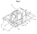
- FIG. 3 is a perspective view illustrating the construction of a conventional upper frame on which the cabin 14 is mounted.
- the cabin 14 includes a base plate (not shown) installed on the bottom surface thereof, a vertically extended front pillar 30, a vertically extended center pillar 32, and a vertically extended rear pillar 34 that are assembled on the front, middle, and rear portions of the base plate by fastening means, respectively.
- a door and a window are installed among the pillars 30, 32, and 34 by welding or bolting.
- a reinforcing member may be provided in the pillars 30, 32, and 34.
- the load is preferentially dispersed by the pillars or the reinforcing member to protect the operator.
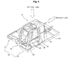
- FIG. 4 is a perspective view illustrating the state in which the vertical load and the rearward load are applied to the cabin of FIG. 3, there is a problem that when the cabin 14 is plastically deformed by the vertical load or rearward load, the upper frame 18 cannot effectively support the vertical strength of the pillars 30, 32, and 34 or the reinforcing member, or cannot disperse the excessive vertical load or rearward load.
- the load is dispersed by the pillar or reinforcing member of the cabin structure, but the dispersed load is not again dispersed by the upper frame.
- an object of the present invention is to provide a structure of an upper frame for supporting a cabin of construction machinery, whereby a cabin structure is effectively supported on the upper frame although the cabin structure is plastically deformed by a vertical load or rearward load.
- a structure of an upper frame for supporting a cabin of construction machinery including a center frame having a lower plate fitted with a swing ring gear and a lateral plate vertically mounted on the lower plate and fitted with operation devices such as a boom, an arm, or a bucket; there is also a left frame mounted on the left side of the center frame, having a side channel extended in a longitudinal direction of the center frame and a plurality of side frames for connecting the center frame with the side channel, according to the present invention, which includes a cabin supporting structure composed of a supporting structure, mounted on the lower plate or lateral plate of the center frame, for supporting a vertical load and a rearward load applied to the cabin.
- the cab supporting structure may include a transverse member disposed under the cabin, with the member being spaced apart from a base plate of the cabin at a specified interval, for supporting the cabin upwardly when a load is applied to the cabin in a downward or forward direction; there is also a vertical member fixed to the bottom plate or side plate of the center frame for supporting the transverse member.
- the transverse member is a circular member made in a curved shape.
- the transverse member is a polygonal member made in a straight shape.
- the transverse member is a member mixed with a curved line and a straight line.
- the vertical member is at least one circular member vertically extended and made in a curved section.
- the vertical member is at least one polygonal member vertically extended and made in a straight section.
- the vertical member is at least one member vertically extended and made in a section mixed with a curved shape and a straight shape.
- One side of the vertical member is welded to the lateral plate of the center frame, and the lower side of the vertical member is welded to the lower plate of the center frame.
- One side of the vertical member is fastened to the lateral plate of the center frame by a bolt, and the lower side of the vertical member is fastened to the lower plate of the center frame by a bolt.
- a lower side of the vertical member is welded to the lower plate of the center frame.
- One side of the vertical member and one side of the vertical member are welded to the lateral plate of the center frame, and the lower side of each vertical member is welded to the lower plate of the center frame at a specified interval.
- One side of the vertical member and one side of the vertical member are welded to the lateral plate of the center frame, and the lower side of each vertical member is spaced apart from the lower plate of the center frame at a specified interval.
- a structure of an upper frame for supporting a cabin of construction machinery including a center frame having a lower plate fitted with a swing ring gear and a lateral plate vertically mounted on the lower plate and fitted with operation devices such as a boom, an arm, or a bucket; there is also a left frame mounted on the left side of the center frame, having a side channel extended in a longitudinal direction of the center frame and a plurality of side frames for connecting the center frame with the side channel, which includes a cabin supporting structure composed of a single support member, mounted on the lower plate or lateral plate of the center frame, for supporting a vertical load and a rearward load applied to the cabin.
- the single support member of the cabin supporting structure is formed by casting, and is disposed on the lower plate or lateral plate under the cabin, with the single support member being spaced apart from a base plate of the cabin at a specified interval, so that the single support member supports the cabin upwardly when a load is applied to the cabin in a downward or forward direction.
- the single support member of the cabin supporting structure is formed by forging, and is disposed on the lower plate or lateral plate under the cabin, with the single support member being spaced apart from a base plate of the cabin at a specified interval, so that the single support member supports the cabin upwardly when a load is applied to the cabin in a downward or forward direction.
- the single support member of the cabin supporting structure is formed by bending a sheet, and has a vertical member fixed to the lateral plate by welding and a lateral member fixed to the lower plate by welding, so that the single support member supports the cabin upwardly or rearward when a load is applied to the cabin in a downward or forward direction.
- a structure of an upper frame for supporting a cabin of construction machinery including a center frame having a lower plate fitted with a swing ring gear and a lateral plate vertically mounted on the lower plate and fitted with operation devices such as a boom, an arm, or a bucket; there is also a left frame mounted on the left side of the center frame, having a side channel extended in a longitudinal direction of the center frame and a plurality of side frames for connecting the center frame with the side channel, which includes a cabin supporting structure, mounted on one side of the side channel, for additionally supporting an upper surface of the side channel when a vertical load and a rearward load are applied to the cabin.
- the cabin supporting structure is a sheet bent at a right angle, and has a vertical portion fixed to an inner vertical surface of the side channel and a horizontal portion fixed to a bottom of a horizontal surface of the side channel to reinforce strength of the horizontal surface.
- the cabin supporting structure is a vertical sheet, has one side fixed to an inner vertical surface of the side channel, and has an upper portion fixed to a bottom of a horizontal surface of the side channel to reinforce strength of the horizontal surface.
- a structure of an upper frame for supporting a cabin of construction machinery including a center frame having a lower plate fitted with a swing ring gear and a lateral plate vertically mounted on the lower plate and fitted with operation devices such as a boom, an arm, or a bucket; there is also a left frame mounted on the left side of the center frame, having a side channel extended in a longitudinal direction of the center frame and a plurality of side frames for connecting the center frame with the side channel, which includes a first cabin supporting structure, mounted on the lower plate of the center frame, for supporting a vertical load and a rearward load applied to the cabin, and a second cabin supporting structure, mounted on one side of the side channel, for supporting an upper surface of the side channel when a vertical load and a rearward load are applied to the cabin.
- the structure of the upper frame for supporting the cabin of construction machinery according to the present invention can minimize plastic deformation of the cabin structure when a rollover accident occurs.
- FIG. 5 a structure of an upper frame for supporting a cabin according to a preferred embodiment of the present invention is illustrated.
- construction machinery such as an excavator, includes a lower driving structure (not shown) having wheels or a caterpillar, and a rotatable upper frame 100 mounted on the lower driving structure.
- the upper frame 100 is provided with a cabin 110, in which an operator sits.
- a plurality of vibration absorption devices are installed under the cabin 110 to prevent the vibration generated from the engine the cooling device, which are mounted on the upper frame 100, and the travel and operation of the excavator from being transferred to the cabin 110.
- the vibration absorption devices become ineffective when an excessive vertical load or rearward load, which is beyond the elastic limit of the construction machinery, is applied to the construction machinery due to the rollover of the construction machinery and so on.
- the upper frame structure according to the present invention further includes a cabin supporting structure 140 for effectively dispersing the load to protect the operator when the structure of the cabin 110 is plastically deformed by the excessive load which may destruct the function of the vibration absorption devices, as shown in FIG. 5.
- the upper frame 100 includes a center frame 120 fitted with operation devices, such as a boom or an arm, and a left frame 130 mounted on the left side of the center frame 120.
- the center frame 120 has a lower plate 122 fitted with a swing ring gear, and a lateral plate 124 vertically mounted on the lower plate 122 and connected to the operation device.
- the left frame 130 has a side channel 132 extended in a longitudinal direction, and a plurality of side frames 134 extended in a horizontal direction for connecting the center frame 120 with the side channel 132.
- the cabin supporting structure has a first cabin supporting structure 140 mounted on the lower plate 122 or the lateral plate 124 of the center frame 120, and a second cabin supporting structure 170 mounted on the side channel 132 of the left frame 130.
- the first cabin supporting structure 140 of the present invention is mounted on the lower plate 122 and the lateral plate 124 of the center frame 120, and it may be composed of a support structure or single support member.
- the support structure 150 is disposed under the cabin 110, with it being spaced apart from the lower portion of the cabin at a specified interval.
- the support structure 150 has a transverse member 152 for supporting the cabin 110 when the load is vertically applied to the cabin 110, and a vertical member 154 fixed to the lower plate 122 for supporting the transverse member 152.
- the transverse member 152 may be formed of a flat plate which is flush with a horizontal surface of the side frame 134 or has a height similar to that of the side frame 134.
- the transverse member may have a circular shape, a polygonal shape, or any shape combined with the circular shape and the polygonal shape.
- the vertical member 154 may be a closed column extended in a vertical direction and formed in a circular shape, a polygonal shape, or any shape combined with the circular shape and the polygonal shape.
- the vertical member 154 is an open column.
- the structure 150 is attached to the center frame 120 by welding, but the present invention is not limited thereto.
- the support structure 150 may be fastened to the center frame by bolts. Since the center frame may be thermally deformed by the welding, it is preferable that the support structure 150 is welded to the lower plate 122 or lateral plate 124 of the center frame 120, before the lower plate 122 and the lateral plate 124 are machined.
- the load applied to the structure of the cabin 110 is effectively dispersed by mounting the first cabin supporting structure 140 at a position corresponding to the lower portion of the pillar or reinforcing member of the cabin 110.
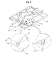
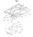
- FIGs. 6 and 7 are perspective views illustrating the structure of the upper frame supporting the cabin according to another embodiment of the present invention.
- the member has the same shape as that of the support structure as shown in FIG. 5 or has a shape similar to that.
- the single support member may be a cast member 160 made by casting shown in FIG. 6, or a sheet metal member 162 made by metal sheet forming shown in FIG. 7.
- the attachment of the single support member 162 to the upper frame 100 is achieved by welding the transverse member 164 to the lateral plate 124 of the center frame 120, welding the vertical member 166 to the lower plate 122 of the center frame 120, or welding the vertical member 166 and the transverse member 164 to the lower plate 122 and lateral plate 124, respectively.
- any method of effectively supporting the vertical load of the cabin may be employed.
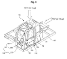
- FIG. 8 is a perspective view illustrating the construction of the upper frame on which the cabin is mounted, according to an embodiment of the present invention.
- the second cabin supporting structure is adapted to additionally support the upper surface of the side channel 132.
- the second cabin supporting structure 170 is an angled sheet that has a vertical portion 172 fixed to an inner vertical surface of the side channel and a horizontal portion 174 fixed to the bottom of the horizontal surface of the side channel to reinforce the strength of the horizontal surface.
- the second cabin supporting structure 170 can also be attached to the side channel 132 by welding or bolting.
- the second cabin supporting structure 170 is not limited to the shape of the sheet, as well as the first cabin supporting structure 140, and a cast member may be employed.
- the vertical load or rearward load generated in the event of the rollover accident is primarily dispersed by the reinforcing member of the cabin structure, such as pillar or reinforcing member, and the dispersed load is again dispersed by providing the upper frame, on which the cabin is mounted, with the additional cabin supporting structure, as shown in FIG. 8, so that the plastic deformation of the cabin structure due to the excessive load can be minimized, as shown in FIG. 9.
- an excessive vertical load or rearward load applied to a cabin structure is primarily dispersed by a reinforcing member of the cabin structure, and the dispersed load is supported by the separate cabin supporting structure, so that the plastic deformation of the cabin structure can be minimized.
Landscapes
- Engineering & Computer Science (AREA)
- Mining & Mineral Resources (AREA)
- Civil Engineering (AREA)
- General Engineering & Computer Science (AREA)
- Structural Engineering (AREA)
- Body Structure For Vehicles (AREA)
- Component Parts Of Construction Machinery (AREA)
Applications Claiming Priority (1)
| Application Number | Priority Date | Filing Date | Title |
|---|---|---|---|
| KR1020050067283A KR100689293B1 (ko) | 2005-07-25 | 2005-07-25 | 건설기계의 운전실 캡을 지지하는 상부프레임 구조 |
Publications (3)
| Publication Number | Publication Date |
|---|---|
| EP1748113A2 true EP1748113A2 (de) | 2007-01-31 |
| EP1748113A3 EP1748113A3 (de) | 2013-11-06 |
| EP1748113B1 EP1748113B1 (de) | 2019-10-16 |
Family
ID=37264611
Family Applications (1)
| Application Number | Title | Priority Date | Filing Date |
|---|---|---|---|
| EP06014219.7A Ceased EP1748113B1 (de) | 2005-07-25 | 2006-07-10 | Baumaschine mit Oberwagenrahmenstruktur zur Abstützung der Kabine |
Country Status (5)
| Country | Link |
|---|---|
| US (1) | US7665801B2 (de) |
| EP (1) | EP1748113B1 (de) |
| JP (1) | JP4411303B2 (de) |
| KR (1) | KR100689293B1 (de) |
| CN (1) | CN1904235B (de) |
Cited By (3)
| Publication number | Priority date | Publication date | Assignee | Title |
|---|---|---|---|---|
| EP2141065A1 (de) * | 2008-07-04 | 2010-01-06 | Volvo Construction Equipment Holding Sweden AB | Schutzstruktur für die Fahrerkabine einer Baumaschine |
| WO2014069684A1 (ko) * | 2012-10-30 | 2014-05-08 | 볼보 컨스트럭션 이큅먼트 에이비 | 엔진 및 관련 부품을 고정하는 보조 프레임 |
| EP2453063A3 (de) * | 2010-11-10 | 2014-12-03 | Kobelco Construction Machinery Co. Ltd. | Oberrahmen für eine Baumaschine |
Families Citing this family (19)
| Publication number | Priority date | Publication date | Assignee | Title |
|---|---|---|---|---|
| JP4655815B2 (ja) * | 2005-08-12 | 2011-03-23 | コベルコ建機株式会社 | 建設機械のキャビン |
| JP2007107291A (ja) * | 2005-10-14 | 2007-04-26 | Kobelco Contstruction Machinery Ltd | 保護部材の取付構造及びこれを備えた作業機械 |
| KR100753991B1 (ko) * | 2006-09-22 | 2007-08-31 | 볼보 컨스트럭션 이키프먼트 홀딩 스웨덴 에이비 | 건설기계의 운전실 캡을 지지하는 상부 프레임 구조 |
| WO2008147410A1 (en) * | 2007-05-26 | 2008-12-04 | Koss Michael J | Retrofitable rops reinforcement structure for cab riser interface |
| KR100979429B1 (ko) * | 2008-02-27 | 2010-09-02 | 볼보 컨스트럭션 이키프먼트 홀딩 스웨덴 에이비 | 건설기계의 상부프레임 |
| JP2010043412A (ja) * | 2008-08-09 | 2010-02-25 | Kobelco Contstruction Machinery Ltd | 作業機械のキャブ補強構造 |
| JP5108709B2 (ja) * | 2008-09-30 | 2012-12-26 | 株式会社神戸製鋼所 | 建設機械のキャビン防音装置 |
| US8267217B2 (en) * | 2009-09-29 | 2012-09-18 | Kubota Corporation | Swivel frame |
| DE102010015163A1 (de) * | 2010-04-16 | 2011-10-20 | Liebherr-Hydraulikbagger Gmbh | Baumaschine oder Umschlaggerät |
| JP5415384B2 (ja) * | 2010-09-21 | 2014-02-12 | 日立建機株式会社 | 建設機械の旋回フレーム |
| JP5790016B2 (ja) * | 2011-02-18 | 2015-10-07 | コベルコ建機株式会社 | ハイブリッド建設機械 |
| JP2013087455A (ja) * | 2011-10-14 | 2013-05-13 | Kobelco Contstruction Machinery Ltd | 作業機械 |
| CN102839706B (zh) * | 2012-09-27 | 2014-07-16 | 太原重工股份有限公司 | 一种大型矿用液压挖掘机上部平台 |
| JP2014105499A (ja) | 2012-11-28 | 2014-06-09 | Kobelco Contstruction Machinery Ltd | 建設機械のアッパーフレーム |
| JP6174969B2 (ja) * | 2013-10-29 | 2017-08-02 | キャタピラー エス エー アール エル | 建設機械のキャブ支持構造 |
| KR102644709B1 (ko) * | 2017-02-28 | 2024-03-06 | 에이치디현대인프라코어 주식회사 | 건설기계의 캐빈 조립체 |
| CN107140037A (zh) * | 2017-06-21 | 2017-09-08 | 徐州徐工矿山机械有限公司 | 一种矿用自卸车驾驶室底板防护结构 |
| JP7236942B2 (ja) * | 2019-06-19 | 2023-03-10 | 株式会社小松製作所 | 作業車両 |
| JP7330837B2 (ja) | 2019-09-26 | 2023-08-22 | 住友建機株式会社 | ショベル |
Family Cites Families (26)
| Publication number | Priority date | Publication date | Assignee | Title |
|---|---|---|---|---|
| JPH0642012A (ja) * | 1992-07-22 | 1994-02-15 | Hitachi Constr Mach Co Ltd | 作業機の運転室 |
| JPH08184075A (ja) * | 1994-12-28 | 1996-07-16 | Komatsu Ltd | 建設機械の保護装置 |
| CN1069373C (zh) * | 1996-06-04 | 2001-08-08 | 日立建机株式会社 | 带驾驶室的工程机械 |
| JPH10292434A (ja) * | 1997-04-17 | 1998-11-04 | Hitachi Constr Mach Co Ltd | 運転室付き作業機 |
| KR200168768Y1 (ko) * | 1997-08-29 | 2000-02-01 | 추호석 | 굴삭기의 선회프레임 |
| JP2000120107A (ja) | 1998-10-19 | 2000-04-25 | Hitachi Constr Mach Co Ltd | 旋回式建設機械 |
| JP2001040706A (ja) * | 1999-08-03 | 2001-02-13 | Komatsu Ltd | 建設機械の旋回台 |
| JP2001173017A (ja) | 1999-12-17 | 2001-06-26 | Hitachi Constr Mach Co Ltd | 建設機械 |
| KR100333889B1 (ko) * | 1999-12-21 | 2002-04-25 | 류정열 | 자동차용 프레임의 보강을 위한 보강구조 |
| JP4150486B2 (ja) * | 2000-05-18 | 2008-09-17 | 日立建機株式会社 | 建設機械の旋回フレーム |
| JP3634723B2 (ja) * | 2000-05-31 | 2005-03-30 | 日立建機株式会社 | 建設機械の旋回フレーム |
| US6568746B2 (en) * | 2000-09-18 | 2003-05-27 | Hitachi Construction Machinery Co., Ltd. | Cab for construction machinery |
| DE60130128T2 (de) * | 2000-09-18 | 2008-05-15 | Hitachi Construction Machinery Co., Ltd. | Fahrerhaus für erdbewegungsmaschinen |
| JP4567242B2 (ja) * | 2001-07-09 | 2010-10-20 | 日立建機株式会社 | 建設機械の旋回フレーム |
| JP2003082705A (ja) * | 2001-09-10 | 2003-03-19 | Hitachi Constr Mach Co Ltd | 建設機械の旋回フレームおよびその製造方法 |
| JP2004108039A (ja) * | 2002-09-19 | 2004-04-08 | Hitachi Constr Mach Co Ltd | 建設機械の旋回フレーム |
| JP2004189003A (ja) * | 2002-12-06 | 2004-07-08 | Komatsu Ltd | 建設機械のクローラフレーム |
| JP4429595B2 (ja) * | 2002-12-11 | 2010-03-10 | 株式会社小松製作所 | キャブ支持構造 |
| JP2005023718A (ja) * | 2003-07-01 | 2005-01-27 | Komatsu Ltd | 建設機械 |
| GB2418661B (en) * | 2003-07-01 | 2007-01-17 | Komatsu Mfg Co Ltd | Construction machine and projecting member thereof` |
| SE526115C2 (sv) * | 2003-08-25 | 2005-07-05 | Volvo Constr Equip Holding Se | Anordning vid en hytt hos ett fordon |
| JP4191585B2 (ja) * | 2003-12-15 | 2008-12-03 | 日立建機株式会社 | 建設機械用キャブ |
| JP4619168B2 (ja) * | 2005-03-28 | 2011-01-26 | 株式会社クボタ | 旋回作業機 |
| KR100702179B1 (ko) * | 2005-05-06 | 2007-04-02 | 볼보 컨스트럭션 이키프먼트 홀딩 스웨덴 에이비 | 중장비 운전실 보호구조 |
| JP4655815B2 (ja) * | 2005-08-12 | 2011-03-23 | コベルコ建機株式会社 | 建設機械のキャビン |
| JP2007107291A (ja) * | 2005-10-14 | 2007-04-26 | Kobelco Contstruction Machinery Ltd | 保護部材の取付構造及びこれを備えた作業機械 |
-
2005
- 2005-07-25 KR KR1020050067283A patent/KR100689293B1/ko not_active Expired - Fee Related
-
2006
- 2006-07-05 US US11/481,286 patent/US7665801B2/en active Active
- 2006-07-05 JP JP2006185268A patent/JP4411303B2/ja not_active Expired - Fee Related
- 2006-07-06 CN CN2006101031727A patent/CN1904235B/zh not_active Expired - Fee Related
- 2006-07-10 EP EP06014219.7A patent/EP1748113B1/de not_active Ceased
Cited By (3)
| Publication number | Priority date | Publication date | Assignee | Title |
|---|---|---|---|---|
| EP2141065A1 (de) * | 2008-07-04 | 2010-01-06 | Volvo Construction Equipment Holding Sweden AB | Schutzstruktur für die Fahrerkabine einer Baumaschine |
| EP2453063A3 (de) * | 2010-11-10 | 2014-12-03 | Kobelco Construction Machinery Co. Ltd. | Oberrahmen für eine Baumaschine |
| WO2014069684A1 (ko) * | 2012-10-30 | 2014-05-08 | 볼보 컨스트럭션 이큅먼트 에이비 | 엔진 및 관련 부품을 고정하는 보조 프레임 |
Also Published As
| Publication number | Publication date |
|---|---|
| CN1904235B (zh) | 2010-09-29 |
| EP1748113B1 (de) | 2019-10-16 |
| KR20070012994A (ko) | 2007-01-30 |
| KR100689293B1 (ko) | 2007-03-02 |
| US20070018484A1 (en) | 2007-01-25 |
| EP1748113A3 (de) | 2013-11-06 |
| US7665801B2 (en) | 2010-02-23 |
| JP2007030866A (ja) | 2007-02-08 |
| CN1904235A (zh) | 2007-01-31 |
| JP4411303B2 (ja) | 2010-02-10 |
Similar Documents
| Publication | Publication Date | Title |
|---|---|---|
| US7665801B2 (en) | Structure of upper frame for supporting cabin of construction machinery | |
| JP4987644B2 (ja) | 建設機械の運転室を支持する上部フレーム構造 | |
| JP5666234B2 (ja) | 建設機械 | |
| JP5996122B2 (ja) | 作業車両のキャブ及びその製造方法 | |
| CN1980827B (zh) | 建筑机械的驾驶室 | |
| JP2001173017A (ja) | 建設機械 | |
| JP4609570B2 (ja) | 建設機械のフレーム構造 | |
| JP2007205100A (ja) | 建設機械の車体フレームおよび建設機械 | |
| JP2007063839A (ja) | 建設機械用保護構造物及び建設機械用キャブ | |
| JP2010270557A (ja) | 建設機械におけるキャブの支持構造 | |
| JP4191585B2 (ja) | 建設機械用キャブ | |
| JP4327658B2 (ja) | 建設機械用キャブ | |
| EP1754835A1 (de) | Dacheinbaustruktur bei arbeitsfahrzeug | |
| KR20050046582A (ko) | 건설 기계 | |
| JP2010065436A (ja) | ローダ作業機のキャビン装置 | |
| JP4824996B2 (ja) | キャブ構造 | |
| JP4544514B2 (ja) | 建設機械用キャブ | |
| JP5055334B2 (ja) | 建設機械のキャブ支持構造 | |
| JP5112149B2 (ja) | 柱支持構造および建設機械用キャブ | |
| JP2007069822A (ja) | キャブおよび作業機械 | |
| JP2007055368A (ja) | キャブ用補強部材、キャブおよび作業機械 | |
| JP2004268907A (ja) | 建設機械のキャノピ構造 | |
| JP2002242229A (ja) | 建設機械の運転室設置構造 | |
| JP2007083786A (ja) | キャブおよび作業機械 | |
| JP2009287391A (ja) | 建設機械 |
Legal Events
| Date | Code | Title | Description |
|---|---|---|---|
| PUAI | Public reference made under article 153(3) epc to a published international application that has entered the european phase |
Free format text: ORIGINAL CODE: 0009012 |
|
| 17P | Request for examination filed |
Effective date: 20060710 |
|
| AK | Designated contracting states |
Kind code of ref document: A2 Designated state(s): AT BE BG CH CY CZ DE DK EE ES FI FR GB GR HU IE IS IT LI LT LU LV MC NL PL PT RO SE SI SK TR |
|
| AX | Request for extension of the european patent |
Extension state: AL BA HR MK YU |
|
| PUAL | Search report despatched |
Free format text: ORIGINAL CODE: 0009013 |
|
| AK | Designated contracting states |
Kind code of ref document: A3 Designated state(s): AT BE BG CH CY CZ DE DK EE ES FI FR GB GR HU IE IS IT LI LT LU LV MC NL PL PT RO SE SI SK TR |
|
| AX | Request for extension of the european patent |
Extension state: AL BA HR MK RS |
|
| RIC1 | Information provided on ipc code assigned before grant |
Ipc: E02F 9/08 20060101ALI20131001BHEP Ipc: E02F 9/12 20060101AFI20131001BHEP |
|
| AKX | Designation fees paid |
Designated state(s): DE FR GB IT |
|
| STAA | Information on the status of an ep patent application or granted ep patent |
Free format text: STATUS: EXAMINATION IS IN PROGRESS |
|
| 17Q | First examination report despatched |
Effective date: 20181119 |
|
| GRAP | Despatch of communication of intention to grant a patent |
Free format text: ORIGINAL CODE: EPIDOSNIGR1 |
|
| STAA | Information on the status of an ep patent application or granted ep patent |
Free format text: STATUS: GRANT OF PATENT IS INTENDED |
|
| INTG | Intention to grant announced |
Effective date: 20190508 |
|
| GRAS | Grant fee paid |
Free format text: ORIGINAL CODE: EPIDOSNIGR3 |
|
| GRAA | (expected) grant |
Free format text: ORIGINAL CODE: 0009210 |
|
| STAA | Information on the status of an ep patent application or granted ep patent |
Free format text: STATUS: THE PATENT HAS BEEN GRANTED |
|
| AK | Designated contracting states |
Kind code of ref document: B1 Designated state(s): DE FR GB IT |
|
| REG | Reference to a national code |
Ref country code: GB Ref legal event code: FG4D |
|
| REG | Reference to a national code |
Ref country code: DE Ref legal event code: R096 Ref document number: 602006058694 Country of ref document: DE |
|
| REG | Reference to a national code |
Ref country code: DE Ref legal event code: R097 Ref document number: 602006058694 Country of ref document: DE |
|
| PLBE | No opposition filed within time limit |
Free format text: ORIGINAL CODE: 0009261 |
|
| STAA | Information on the status of an ep patent application or granted ep patent |
Free format text: STATUS: NO OPPOSITION FILED WITHIN TIME LIMIT |
|
| PG25 | Lapsed in a contracting state [announced via postgrant information from national office to epo] |
Ref country code: IT Free format text: LAPSE BECAUSE OF FAILURE TO SUBMIT A TRANSLATION OF THE DESCRIPTION OR TO PAY THE FEE WITHIN THE PRESCRIBED TIME-LIMIT Effective date: 20191016 |
|
| 26N | No opposition filed |
Effective date: 20200717 |
|
| GBPC | Gb: european patent ceased through non-payment of renewal fee |
Effective date: 20200710 |
|
| PG25 | Lapsed in a contracting state [announced via postgrant information from national office to epo] |
Ref country code: GB Free format text: LAPSE BECAUSE OF NON-PAYMENT OF DUE FEES Effective date: 20200710 |
|
| PGFP | Annual fee paid to national office [announced via postgrant information from national office to epo] |
Ref country code: DE Payment date: 20220527 Year of fee payment: 17 |
|
| PGFP | Annual fee paid to national office [announced via postgrant information from national office to epo] |
Ref country code: FR Payment date: 20220725 Year of fee payment: 17 |
|
| REG | Reference to a national code |
Ref country code: DE Ref legal event code: R119 Ref document number: 602006058694 Country of ref document: DE |
|
| PG25 | Lapsed in a contracting state [announced via postgrant information from national office to epo] |
Ref country code: DE Free format text: LAPSE BECAUSE OF NON-PAYMENT OF DUE FEES Effective date: 20240201 |
|
| PG25 | Lapsed in a contracting state [announced via postgrant information from national office to epo] |
Ref country code: FR Free format text: LAPSE BECAUSE OF NON-PAYMENT OF DUE FEES Effective date: 20230731 |