EP1735896B1 - Element de reglage destine a un siege de vehicule - Google Patents
Element de reglage destine a un siege de vehicule Download PDFInfo
- Publication number
- EP1735896B1 EP1735896B1 EP05738820A EP05738820A EP1735896B1 EP 1735896 B1 EP1735896 B1 EP 1735896B1 EP 05738820 A EP05738820 A EP 05738820A EP 05738820 A EP05738820 A EP 05738820A EP 1735896 B1 EP1735896 B1 EP 1735896B1
- Authority
- EP
- European Patent Office
- Prior art keywords
- gear
- adjuster
- motor
- load
- gear stage
- Prior art date
- Legal status (The legal status is an assumption and is not a legal conclusion. Google has not performed a legal analysis and makes no representation as to the accuracy of the status listed.)
- Expired - Fee Related
Links
- 230000001105 regulatory effect Effects 0.000 title claims abstract 3
- 230000001360 synchronised effect Effects 0.000 claims description 4
- 238000003825 pressing Methods 0.000 claims description 2
- 230000015572 biosynthetic process Effects 0.000 claims 1
- 230000005540 biological transmission Effects 0.000 abstract description 35
- 238000013461 design Methods 0.000 description 18
- 239000002184 metal Substances 0.000 description 14
- 229910052751 metal Inorganic materials 0.000 description 14
- 229920001971 elastomer Polymers 0.000 description 12
- 230000033001 locomotion Effects 0.000 description 12
- 239000000806 elastomer Substances 0.000 description 11
- 230000004323 axial length Effects 0.000 description 6
- 230000000903 blocking effect Effects 0.000 description 6
- 230000010354 integration Effects 0.000 description 6
- 230000009467 reduction Effects 0.000 description 6
- 230000008901 benefit Effects 0.000 description 5
- 238000010276 construction Methods 0.000 description 5
- 238000004519 manufacturing process Methods 0.000 description 4
- 230000002093 peripheral effect Effects 0.000 description 4
- 238000005096 rolling process Methods 0.000 description 4
- 230000008859 change Effects 0.000 description 3
- 230000004907 flux Effects 0.000 description 3
- 150000002739 metals Chemical class 0.000 description 3
- 230000004048 modification Effects 0.000 description 3
- 238000012986 modification Methods 0.000 description 3
- 238000003860 storage Methods 0.000 description 3
- XEEYBQQBJWHFJM-UHFFFAOYSA-N Iron Chemical compound [Fe] XEEYBQQBJWHFJM-UHFFFAOYSA-N 0.000 description 2
- 230000008878 coupling Effects 0.000 description 2
- 238000010168 coupling process Methods 0.000 description 2
- 238000005859 coupling reaction Methods 0.000 description 2
- 238000009434 installation Methods 0.000 description 2
- 235000012771 pancakes Nutrition 0.000 description 2
- 230000035699 permeability Effects 0.000 description 2
- IHQKEDIOMGYHEB-UHFFFAOYSA-M sodium dimethylarsinate Chemical class [Na+].C[As](C)([O-])=O IHQKEDIOMGYHEB-UHFFFAOYSA-M 0.000 description 2
- 239000007787 solid Substances 0.000 description 2
- 238000013519 translation Methods 0.000 description 2
- 229910000831 Steel Inorganic materials 0.000 description 1
- 239000000969 carrier Substances 0.000 description 1
- 238000004891 communication Methods 0.000 description 1
- 239000004020 conductor Substances 0.000 description 1
- 239000000470 constituent Substances 0.000 description 1
- 230000001419 dependent effect Effects 0.000 description 1
- 238000001514 detection method Methods 0.000 description 1
- 238000010586 diagram Methods 0.000 description 1
- 230000000694 effects Effects 0.000 description 1
- 230000008030 elimination Effects 0.000 description 1
- 238000003379 elimination reaction Methods 0.000 description 1
- 238000011156 evaluation Methods 0.000 description 1
- 230000002349 favourable effect Effects 0.000 description 1
- 210000003746 feather Anatomy 0.000 description 1
- 239000000835 fiber Substances 0.000 description 1
- 230000020169 heat generation Effects 0.000 description 1
- 238000010348 incorporation Methods 0.000 description 1
- 229910052742 iron Inorganic materials 0.000 description 1
- 239000000463 material Substances 0.000 description 1
- 238000012544 monitoring process Methods 0.000 description 1
- 239000010959 steel Substances 0.000 description 1
- 230000036962 time dependent Effects 0.000 description 1
- 238000012549 training Methods 0.000 description 1
- 238000004804 winding Methods 0.000 description 1
Images


Classifications
-
- B—PERFORMING OPERATIONS; TRANSPORTING
- B60—VEHICLES IN GENERAL
- B60N—SEATS SPECIALLY ADAPTED FOR VEHICLES; VEHICLE PASSENGER ACCOMMODATION NOT OTHERWISE PROVIDED FOR
- B60N2/00—Seats specially adapted for vehicles; Arrangement or mounting of seats in vehicles
- B60N2/02—Seats specially adapted for vehicles; Arrangement or mounting of seats in vehicles the seat or part thereof being movable, e.g. adjustable
- B60N2/22—Seats specially adapted for vehicles; Arrangement or mounting of seats in vehicles the seat or part thereof being movable, e.g. adjustable the back-rest being adjustable
-
- H—ELECTRICITY
- H02—GENERATION; CONVERSION OR DISTRIBUTION OF ELECTRIC POWER
- H02K—DYNAMO-ELECTRIC MACHINES
- H02K7/00—Arrangements for handling mechanical energy structurally associated with dynamo-electric machines, e.g. structural association with mechanical driving motors or auxiliary dynamo-electric machines
- H02K7/10—Structural association with clutches, brakes, gears, pulleys or mechanical starters
- H02K7/116—Structural association with clutches, brakes, gears, pulleys or mechanical starters with gears
-
- B—PERFORMING OPERATIONS; TRANSPORTING
- B60—VEHICLES IN GENERAL
- B60N—SEATS SPECIALLY ADAPTED FOR VEHICLES; VEHICLE PASSENGER ACCOMMODATION NOT OTHERWISE PROVIDED FOR
- B60N2/00—Seats specially adapted for vehicles; Arrangement or mounting of seats in vehicles
- B60N2/02—Seats specially adapted for vehicles; Arrangement or mounting of seats in vehicles the seat or part thereof being movable, e.g. adjustable
- B60N2/0224—Non-manual adjustments, e.g. with electrical operation
- B60N2/02246—Electric motors therefor
- B60N2/02253—Electric motors therefor characterised by the transmission between the electric motor and the seat or seat parts
-
- B—PERFORMING OPERATIONS; TRANSPORTING
- B60—VEHICLES IN GENERAL
- B60N—SEATS SPECIALLY ADAPTED FOR VEHICLES; VEHICLE PASSENGER ACCOMMODATION NOT OTHERWISE PROVIDED FOR
- B60N2/00—Seats specially adapted for vehicles; Arrangement or mounting of seats in vehicles
- B60N2/02—Seats specially adapted for vehicles; Arrangement or mounting of seats in vehicles the seat or part thereof being movable, e.g. adjustable
- B60N2/22—Seats specially adapted for vehicles; Arrangement or mounting of seats in vehicles the seat or part thereof being movable, e.g. adjustable the back-rest being adjustable
- B60N2/225—Seats specially adapted for vehicles; Arrangement or mounting of seats in vehicles the seat or part thereof being movable, e.g. adjustable the back-rest being adjustable by cycloidal or planetary mechanisms
- B60N2/2251—Seats specially adapted for vehicles; Arrangement or mounting of seats in vehicles the seat or part thereof being movable, e.g. adjustable the back-rest being adjustable by cycloidal or planetary mechanisms with gears having orbital motion, e.g. sun and planet gears
-
- B—PERFORMING OPERATIONS; TRANSPORTING
- B60—VEHICLES IN GENERAL
- B60N—SEATS SPECIALLY ADAPTED FOR VEHICLES; VEHICLE PASSENGER ACCOMMODATION NOT OTHERWISE PROVIDED FOR
- B60N2/00—Seats specially adapted for vehicles; Arrangement or mounting of seats in vehicles
- B60N2/02—Seats specially adapted for vehicles; Arrangement or mounting of seats in vehicles the seat or part thereof being movable, e.g. adjustable
- B60N2/22—Seats specially adapted for vehicles; Arrangement or mounting of seats in vehicles the seat or part thereof being movable, e.g. adjustable the back-rest being adjustable
- B60N2/225—Seats specially adapted for vehicles; Arrangement or mounting of seats in vehicles the seat or part thereof being movable, e.g. adjustable the back-rest being adjustable by cycloidal or planetary mechanisms
- B60N2/2254—Seats specially adapted for vehicles; Arrangement or mounting of seats in vehicles the seat or part thereof being movable, e.g. adjustable the back-rest being adjustable by cycloidal or planetary mechanisms provided with braking systems
-
- B—PERFORMING OPERATIONS; TRANSPORTING
- B60—VEHICLES IN GENERAL
- B60N—SEATS SPECIALLY ADAPTED FOR VEHICLES; VEHICLE PASSENGER ACCOMMODATION NOT OTHERWISE PROVIDED FOR
- B60N2/00—Seats specially adapted for vehicles; Arrangement or mounting of seats in vehicles
- B60N2/02—Seats specially adapted for vehicles; Arrangement or mounting of seats in vehicles the seat or part thereof being movable, e.g. adjustable
- B60N2/22—Seats specially adapted for vehicles; Arrangement or mounting of seats in vehicles the seat or part thereof being movable, e.g. adjustable the back-rest being adjustable
- B60N2/235—Seats specially adapted for vehicles; Arrangement or mounting of seats in vehicles the seat or part thereof being movable, e.g. adjustable the back-rest being adjustable by gear-pawl type mechanisms
- B60N2/2352—Seats specially adapted for vehicles; Arrangement or mounting of seats in vehicles the seat or part thereof being movable, e.g. adjustable the back-rest being adjustable by gear-pawl type mechanisms with external pawls
-
- H—ELECTRICITY
- H02—GENERATION; CONVERSION OR DISTRIBUTION OF ELECTRIC POWER
- H02K—DYNAMO-ELECTRIC MACHINES
- H02K7/00—Arrangements for handling mechanical energy structurally associated with dynamo-electric machines, e.g. structural association with mechanical driving motors or auxiliary dynamo-electric machines
- H02K7/14—Structural association with mechanical loads, e.g. with hand-held machine tools or fans
Definitions
- the invention relates to an adjustment device for a vehicle seat with the features of the preamble of claim 1.
- Such adjustment devices are used for motor-adjustable vehicle seats, in order to achieve an optimum seating position for the occupant by moving individual components relative to each other.
- the gear stage By means of the gear stage, the speed can be reduced and at the same time the output torque can be increased.
- An adjusting device of the type mentioned is in the EP 1 110 804 A1 described with a load-receiving gear, a side arranged therefrom gear and a gear stage driving motor, wherein the gear stage and the motor are arranged as a drive unit within a hood-shaped handwheel, which alternatively drives the load-absorbing gear.
- the invention is based on the object to improve a setting device of the type mentioned. This object is achieved by an adjusting device with the features of claim 1. Advantageous embodiments are the subject of the dependent claims.
- the adjuster in the load-receiving transmission, the drive unit is integrated, wherein the load-bearing gear directly or indirectly stored rotates about an axis rotor has the advantage that separate transmission elements between the drive unit and the load-bearing transmission, for example, a poor efficiency worm gear or the like , As well as separate bearing elements for the rotor are dispensable. In addition, if a continuous play-free mounting of the rotor via the gear stage up to the load-bearing gearbox, the running noise is greatly reduced.
- the fitting parts forming the load-bearing gear are movable about or relative to a center, for example a gear meshing with a rack about its hub or two into one another cross fitting parts of an eccentric epicyclic gear around the eccentric.
- very small dimensionable drive unit (motor and gear stage) at least the gear stage, preferably the entire drive unit - at least largely - arranged in this center, ie, approximately in the same plane (or better layer), in the the or the fitting parts move.
- the diameter of the drive unit arranged in the center of the load-receiving transmission is preferably smaller or at most equal to the diameter of the toothings for the gear connection between the fitting parts.
- the required space is kept low, especially in the axial direction defined by the axis of the motor, which is preferably perpendicular to said plane.
- the space gained compared to a known solution can be used for improved load bearing in the event of a crash.
- an insert can also be made at another location in a vehicle, for example in a window regulator, an exterior mirror or a sunroof.
- Electronically commutated, brushless motors offer high electromechanical efficiency with low space and low noise level. Multiple motors can work with the associated electronics substantial additional effort in their speed or position are synchronized with each other.
- the type of commutation offers the possibility of detecting a blocking state, electrically defining a maximum permissible blocking moment and monitoring the temperature, and thus realizing a higher energy density of the electromagnetic converter than brush motors, which allows a significant reduction in installation space and weight.
- the integration of the control electronics into the motor offers advantages in the recognition of block situations, the evaluation of existing sensors and the coordination between the electronic function and the device to be driven, for example when recording or programming parameters of the engine behavior.
- the different speed and / or direction of rotation of the rotors is preferably achieved in a structurally simple manner in that the rotors have a different number of poles with each other, which in turn is preferably different from the number of stator poles, so that the speed of the rotors of the speed deviates from the magnetic field of the stator.
- a ratio of the stator poles to the poles of the rotor which is different from 2: 3 and 3: 2, allows speed and / or rotational direction differences, with which - for example by means of two rotors - a small relative movement can be generated, which leads to a speed reduction with simultaneous Increase of the output side torque leads.
- stator is preferably electronically commutated, while the rotors preferably carry permanent magnets as poles.
- every second stator pole carries a coil in order to move the magnetic flux over the adjacent one Close stator pole.
- Stator and rotors may be arranged with respect to the central axis in radial sequence or axial sequence (pancake).
- the poles of stator and rotors may differ by two, for example.
- the use of permanent magnets with metals from the group of rare earths, the type of winding, which provides a relatively large torque even at low power, and the combination of Poliere2020 each contribute to a further reduction in the space requirement.
- the motor drives with an engine pinion an intermediate wheel which can be positively locked or frictionally locked.
- the motors are combined to form a multi-motor, which can meet different performance requirements in a situation-adapted manner and is space-saving and ergonomically favorable.
- the motors are arranged in parallel engine shafts of a common engine mount, wherein a common intermediate forms the output of the multi-motor.
- a common intermediate forms the output of the multi-motor.
- extremely high power can be called up in the short term. If, for example, the motors of the multi-motor are normally connected in series, then in a particular situation they can be connected in parallel in order to output a higher power due to the higher voltage.
- a situation is, for example, a crash or imminent crash of a vehicle.
- the engine is preferably selected from a plurality of engine variants, in the radial embodiment, for example, an internal rotor, an external rotor or a double rotor motor.
- a selectable from several types of gear stage gear stage with several gear stages can be connected in series, is a modular system available that creates a few drive units with a few modules to cover the various requirements.
- An embodiment of the gear stage as a differential gear which generates a movement of an output about an axis by utilizing two different speeds and / or directions of rotation, particularly small relative movements can be generated, which allow a low speed at the output.
- the two different speeds and / or directions of rotation can be guided by the engine in the transmission stage or generated by the gear stage itself and tapped by setting a component with such a speed on the other component as an output.
- the gear stage is preferably connected to a motor with a preferably electronically commutated stator and at least one magnetically interacting with the stator, rotating around the axis, permanent magnets bearing rotor connected.
- a motor is quiet and runs with low friction.
- the gear stage can be realized in a friction wheel design with hollow and / or solid rollers or a gear design, the former design is easier to manufacture, with hollow rollers is also weight-reducing, and at the same time can serve as a bearing for a rotor.
- the efficiency of the gear stage is important for the overall efficiency of the drive unit, which is why coaxial, fully symmetrical transmission designs with the lowest possible number of individual bearings, especially in Reibrad-execution without any additional storage but rather with its own Lager galntation preferred.
- the gear stage may be formed as a single-stage planetary differential gear with a sun gear, a set of planetary rollers or gears and a ring gear, wherein the sun gear and the ring gear rotatably connected to a respective rotor of the motor, while a planetary rollers or wheels supporting web as Downforce is used.
- the gear stage can also be designed as a multi-stage (ie at least two-stage) planetary differential gear with one or more sun gears, one or more sets of inner planetary rollers, one or more sets of outer planetary rollers and one or more outer rings, which are arranged concentrically to the central axis, wherein the sun gears and the outer rings are arranged axially adjacent to the axis.
- Different outer diameters of the two sun gears or different inner diameters of the two outer rings (or in each case different elasticities) lead to low speed differences.
- the gear stage may also be formed as a single stage planetary differential with one or more sun gears, a set of preferably unrestrained planetary rollers and one or more ring gears concentric with the central axis, the sun gears being disposed axially adjacent to the axis.
- Different elasticities and different outer diameters of the two sun gears or different inner diameters of the two ring gears result in low speed differences.
- the said speed differences can for example be tapped by one of the two said adjacent transmission elements of different diameter of a fixed housing and one connected to the output.
- two outer rings of the housing fixed to the stator is in communication, while serving as a drive sun gear rotatably connected to a rotor of the motor.
- the ring gear or the outer ring preferably have an elastic metal ring and the metal ring receiving elastomer bed.
- An elastomeric bed with the metal ring receiving and axially locking holder is preferably connected to a bell of the output designed as a hollow shaft.
- a manual transmission With a manual transmission, the direction of rotation of the output can be selectively switched without having to change the direction of rotation of the motor. This greatly simplifies the electronics for the engine.
- an electromagnet defined by a switching coil is preferably provided in a simple to manufacture embodiment, which cooperates with two mutually repulsive permanent holding magnets, which are geometrically coupled to two adjacent, similar transmission elements to determine these frictionally or positively.
- With a manual transmission can also be selected between two different transmission ratios.
- the gear stage is preferably selectable from several gear stage types.
- a modular system is available that uses a few modules to create a large number of drive units to cover the various requirements.
- a preferred adjuster is designed as a versatile rotary adjuster, in particular as a self-locking geared fitting with a first fitting part and a second fitting part, which rotate relative to each other by an eccentric driven by the drive unit.
- the fittings can each have a molded collar or an attached sleeve by means of which they store the eccentric and / or at least part of the drive unit, preferably the entire drive unit including electronics for commutation record.
- the eccentric which is preferably mounted on one of the collar or sleeve, is preferably formed by a drivable Mit Meetingsegment, two curved wedge segments, between the Narrow sides of the driver segment engages with game, and one between the facing broad sides of the wedge segments and this in the circumferential direction apart pushing spring for play release.
- a collar pull can be connected to or form the housing or outer ring or ring gear fixed to the housing.
- the driver segment may be formed or mounted on the output of the gear stage, in particular on the second outer ring or ring gear.
- the fitting parts can simultaneously be parts of the magnetic circuit of the motor.
- a drive unit 10 has an engine 12 and a gear stage 14 provided on the output side of the engine 12.
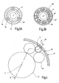
- the motor 12 is an electronically commutated motor with a stator 16, the stator poles 18 are arranged in a star shape about an axis A.
- Axis A perpendicular to the plane of the drawing defines the following directions in cylindrical coordinates.
- first motor variant an internal rotor motor with a radially disposed inside the stator 16 inner rotor 22
- second motor variant an external rotor motor with a radially outside of the stator 16 arranged outer rotor 24
- second motor variant an external rotor motor with a radially outside of the stator 16 arranged outer rotor 24
- third engine variant provided.
- inner rotor 22 and outer rotor 24 rotate about the axis A and carry along the peripheral surface facing the stator 16 permanent magnets 26, which are alternately poled in the circumferential direction.
- All of the permanent magnets 26 used in the present application preferably have a high permeability, for example by containing metals from the group of rare earths.
- An inner yoke ring 28 which is assigned to the inner rotor 22 in the first and third engine variants and to the stator 16 in the second engine variant, and to an outer yoke ring 30 which is assigned to the stator 16 in the first engine variant and to the outer rotor 24 in the second and third engine variants , close the magnetic flux. If appropriate, the two return rings 28 and 30 can simultaneously serve as carriers of the permanent magnets 26.
- the outer rotor 24 provides a larger torque due to the magnetic forces acting on a larger radius (compared to the inner rotor 22). All three engine variants are preferably formed in a hollow shaft design, ie, the area around the axis A is released.
- the number of permanent magnets 26 is selected so that their ratio to the number of stator poles 18 is not equal to 2: 3 or 3: 2, whereby the rotation of the inner rotor 22 and outer rotor 24 from the R-rotation of the magnetic field in the stator 16 deviates.
- the inner rotor 22 has ten permanent magnets 26 and the outer rotor 24 has fourteen permanent magnets 2 6.
- According to the different number of permanent magnets 26 rotate in the third engine variant (duo motor) of the inner rotor 22 and the outer rotor 24 in the present case with different speeds (5: 7) and also in opposite directions of rotation, which is indicated in the drawing by arrows.
- an axial construction can also be realized, i. the rotors (pancake) and the stator are arranged axially one behind the other.
- the gear 14 is used to suppress the speed of the motor 12 while translating the output from the engine 12 torque.
- the gear 14 is designed as a differential gear, wherein different types are described below. For each type exists both a design as a gear planetary differential gear with flat, toothed planet gears and a preferred embodiment as a friction planetary differential gear with cylindrical, smooth planetary rollers, which - as the sun - can be hollow or solid.
- the first gear stage type is a one-stage planetary differential gear, which will be described first in the friction wheel design.
- the gear stage 14 is aligned with the central axis A of the motor 12.
- Around the axis A around a sun gear 32 is arranged, on the peripheral surface of three planetary rollers 34 roll along, which in turn are surrounded by a ring gear 36.
- the ring gear 36 provides a radial bias and thus for a good rolling of the planetary rollers 34 without slippage.
- An annular web 38 carries on axial pin planetary rollers 34th
- the preferred combination of this first gear stage type is done with the third engine variant, the duo engine, but can also be done with the other engine variants, including brush-commutated motors.
- the inner rotor 22 is rotatably connected to the sun gear 32, while the outer rotor 24 is rotatably connected to the ring gear 36.
- the web 38 serves as an output of the drive unit 10.
- the respective diameters are matched in their dimensions to the speeds, torques and directions of rotation of the rotors 22 and 24.
- the axial lengths of the sun gear 32, planetary rollers 34 and ring gear 36 are selected to be so large that by means of the gear stage 14, a bearing of the inner rotor 22 and the outer rotor 24 takes place relative to the stator 16.
- the second gear stage type is a multi-stage planetary differential gear, which in turn is described in the radially layered friction wheel design, but is also possible in a gear design. Likewise, massive and / or hollow components can be used again.
- Around the axis A around a sun gear 32 is again arranged, on the peripheral surface of a layer of inner planetary rollers 34 is arranged.
- first outer planetary roller 40 and a second outer planetary roller 42 Inserted in each intermediate space are axially one behind the other arranged a first outer planetary roller 40 and a second outer planetary roller 42, each having approximately half the axial length of an inner planetary roller 34, wherein the second outer planetary roller 42 with respect to the first outer planetary roller 40 slightly smaller diameter Has, which can be realized for example by the use of cylindrical rollers on the one hand from the metric and on the other hand from the imperial standard series in a simple manner. Instead of the cylindrical shape and a different shape for the rolling elements can be used.
- This bias of the two radially layered rows of rollers ensure that all roles support each other and a concentric radially symmetrical arrangement results, which is without slippage, so that there is a high efficiency of the transmission stage 14.
- a web and thus an inner bearing of the planetary rollers is not required, but not excluded.
- the sun gear 32 may be provided at the end with radially outwardly facing ribs to secure the planetary rollers in the axial direction, which is also possible with the other types of gear stages.
- the two outer rings 44 and 46 are constructed in principle the same, so that in the following only the first outer ring 44 is described.
- the first outer ring 44 has an elastic metal ring 48 made of steel, which rests on its radially inner side of the first outer planetary rollers 40 and is formed with a smaller inner diameter than it requires the geometric arrangement of the enclosed rollers to apply the bias.
- On the radially outer side and on the two axial end faces of the metal ring 48 is located in an elastomer bed 50 of the first outer ring 44.
- the metal ring 48 and the plastic elastomeric bed 50 together ensure a very uniform contact pressure.
- the elastomer bed 50 insulates the running noise and mitigates torque surges.
- the described two-part construction of the first outer ring 44 can also be realized in the ring gear 36 or 36 'of the first gear stage type.
- a holder 52 is provided, which is designed in two parts for the purpose of assembly and the elastomer bed 50 radially on the outside and with two ribs over the front overlaps, which is also possible with the other types of gear stages.
- the metal ring 48 and the elastomer bed 50 are preferably formed continuously in the circumferential direction, but they can also be slotted or split, in particular slotted arrow shape, for example, when they are rotatably connected to the holder 52.
- the elastomer bed 50 is preferably good thermal conductivity, for example by incorporation of metallic or other thermally conductive fibers or filling cavities or cutouts with a thermally conductive material. Between the metal ring 48 and the elastomer bed 50 may also be provided a thermal paste.
- the small difference in diameter between the first outer planetary rollers 40 and the second outer planetary rollers 42 and, consequently, the inner diameters of the first outer ring 44 and the second outer ring 46 causes a difference in the rotational speeds of the two outer rings 44 and 46.
- This small rotational speed difference becomes large Reduction (eg 200) of the gear stage 14 exploited when it is connected to the motor 12.
- the preferred combination of this second gear stage type is carried out with the first or second engine variant, but can also be done with other engine variants, including brush-commutated motors.
- the first outer ring 44 more precisely its holder 52, for example, fixed to the housing, that is connected to the stator 16.
- the serving as a drive sun gear 32 is connected to the inner rotor 22 (or the outer rotor 24 or a web 3 8), while the second outer ring 46 serves as an output 54.
- the second outer ring 46 serves as an output 54.
- the second outer ring 46 serves as a hollow shaft output shaft with a bell-shaped end piece, attached to the second outer ring 46, more precisely on the holder 52.
- the second outer ring 46 rotates in the same direction to the sun gear 32nd
- the selected structure of second gear stage type makes a separate storage of the sun gear 32 and thus the inner rotor 22 (or outer rotor 24) and the second outer ring 46, ie the output 54, dispensable, but does not exclude.
- the bearing of the inner rotor 22 (or outer rotor 24) in the gear stage 14 has the advantage that it is free of play and thus causes a silent running of the inner rotor 22 (or outer rotor 24).
- the (smaller) second outer ring 46 is fixed to the housing and the (larger) first outer ring 44 the output, which causes an opposite rotation of the sun gear 32 and the first outer ring 4-4.
- the outer rings 44 and 46 are fixed to the housing and the (larger) first outer ring 44 the output, which causes an opposite rotation of the sun gear 32 and the first outer ring 4-4.
- a reversal of direction of the output can be achieved with the same direction of rotation of the sun gear 32.
- the required electronics of the motor 12 can then be constructed much simpler, which simplifies the production of the motor 12.
- the second gear stage type can be further modified by a different number of roller sets.
- one or more axially successively arranged sun gears, an equal number of inner planetary rollers in a corresponding axial arrangement, optionally a set of central planetary rollers for synchronization, one or more sets of axially successively arranged, outer planetary rollers and an equal number of outer rings in corresponding be provided axial arrangement.
- the small speed difference is tapped according to the manner described between two adjacent transmission elements.
- the third gear stage type is again a single-stage planetary differential gear, which in turn is described in a radially layered friction wheel design, but also in a gear design is possible.
- the gear stage 14 is aligned with the central axis A of the motor 12.
- About the axis A around a sun gear 32 is arranged on the peripheral surface of three planetary rollers 34 roll along.
- the ungraded planetary rollers 34 are enclosed by an annular first ring gear 36, which has a low elasticity, that is relatively stiff.
- the planetary rollers 34 are enclosed by a second ring gear 56, which has a higher elasticity and a smaller inner circumference than the first ring gear 36.
- the two ring gears 36 and 56 provide a radial bias with high contact pressure and thus for a good rolling of the planetary rollers 34 without slippage, wherein the sun gear 32 compensates for the radial forces.
- the ratio of the ring gear inner circumferences for a translation of 200 need not be 200/199, but can be chosen generous and thus tolerances insensitive.
- a web supporting the planetary rollers may be provided analogously to the first gear stage type as a drive or a bearing cage fixing the planetary rollers.
- sun gears of different elasticity can be provided in a modified embodiment, two axially successively arranged sun gears of different elasticity in combination with a ring gear or other combinations of continuous or divided sun gears and ring gears of different elasticity.
- the planetary rollers can also be stepped.
- the second ring gear 56 received by this radially outwardly enclosing elastomer bed 50, for example, a rubber ring, which in turn is disposed radially within a holder 52.
- the elastomer bed 50 can also be regarded as a further constituent of the ring gear 56 having a metal ring.
- elastic spokes for the second ring gear 56 - or an axial or radial tap possibly with the interposition of a pot with deformable walls or a damper elements having perforated disc may be provided.
- the slightly non-uniform movement of the ring gear 56 is preferably not or only slightly compensated.
- first ring gear 36 is fixed to the housing, i. connected to the stator 16.
- the serving as a drive sun gear 32 is connected to the inner rotor 22 (or the outer rotor 24), while the second ring gear 56 serves as an output 54.
- second ring gear 56 serves as an output 54.
- designed as a hollow shaft output shaft with a bell-shaped end piece on the second ring gear 56 is mounted, more precisely on the holder 52.
- the respective diameter must be at most in the same orders of magnitude, so that there is a further translation option by choosing the diameter.
- the axial lengths of the sun gear 32, planetary rollers 34 and ring gear 36 are selected to be so large that by means of the gear stage 14, a bearing of the inner rotor 22 and the outer rotor 24 takes place relative to the stator 16.
- the third gear stage type is also a separate bearing of the sun gear 32 and thus of the inner rotor 22 (or outer rotor 24) and the second ring gear 56, i. of the output 54, dispensable, but it does not exclude.
- the gear 14 may be designed as a manual transmission, by means of which in a single, always constant direction of rotation of the motor 12, the direction of rotation of the output 54 between two different Abtriebssearchmaschineen is switchable, which explained in more detail below with reference to the second gear stage type is.
- a set of inner planetary rollers 34 seated on the sun gear 32 is a set of inner planetary rollers 34 on which in turn a set of first planetary rollers 40 is disposed biased by a first outer ring 44 and axially displaced therefrom by a set of second planetary rollers 42 a second outer ring 46 is held biased.
- the second outer ring 46 forms part of the output 54.
- the axial length of the inner planetary rollers 34 is selected so that axially adjacent to the first outer ring 44 on the side facing away from the second outer ring 46 side, a third outer ring 58 is arranged, which with bias the inner planet rolls 34 directly includes.
- the outer diameter of the first outer ring 44 and the third outer ring 58 are at least approximately coincident.
- a wrap spring 60 is supported fixed to the housing at its center and otherwise wrapped with a portion of their turns around the first outer ring 44 and with another part of their turns around the third outer ring 58.
- a permanent magnet is arranged in each case as a holding magnet 61, wherein the mutually facing poles of the two holding magnets 61 repel each other.
- the holding magnets 61 preferably have a high permeability, for example by containing metals from the group of rare earths.
- a core 62 made of soft iron is arranged, around which a coil 63 which can be energized with an optional polarity is wound.
- a manual transmission with a positive solution is conceivable in a modified version.
- the holding magnets 61 can recordable manner be arranged on toothed pawls 64 which lock the respective teeth carrying a outer rings switchable. The operation is as described above.
- the locking device can also serve to lock torques in the idle state, which are initiated by the output 54. Such a lock need not take place at the gear stage 14, it may also be provided between the engine 12 and gear 14.
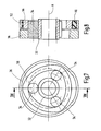
- the output shaft of the motor 12 is provided on the one hand with a motor pinion 66 which engages in an intermediate gear 67 connected to the sun gear 32, and on the other hand frictionally connected to a control disk 68 with two cams 68 '.
- two spring-loaded ratchets 64 engage at least approximately formischlüssig in the intermediate gear 67 and lock this, in particular against the output side introduced torques.
- the control disk 68 is rotated, wherein the cams 68 'come into abutment against control contours 64' of the pawls 64 and thereby dig the pawls 64 from the intermediate gear 67, as in Fig.
- the idler gear 67 can now be driven without hindrance, wherein the frictional engagement with the control disk 68 is preferably canceled.
- the control disk 68 is not frictionally engaged with a rotating axis, but rotatably with the non-rotating motor part and this in turn rotatably supported by a small angular range to the housing.
- the inventively provided drive unit 10 is not limited to a combination of a single motor 12 with a single gear stage 14. Thus, it may be useful for certain performance requirements to combine multiple engines 12, for example, to meet time-varying requirements.
- a motor carrier 70 a plurality of motor wells 71 are provided, which are each arranged around a central bearing for a common idler gear 67.
- the multi-motor 72 thus formed is then coupled by means of the intermediate gear 67 to a gear stage 14, for example to a sun gear 32 of one of the gear stage types described above.
- the type of motor commutation is irrelevant here.
- the mechanically parallel interconnected motors 12 are electrically operated normally in series. In Fig. 16 this is illustrated by two motors 12 and extendable in a conventional manner to a plurality of motors. Between the motors 12, one or more relays 74 are provided, including electronic replacement circuits are to be understood. Normally, due to the series connection, the operating voltage is distributed at least approximately uniformly over the existing motors 12.
- the drive unit 10 may be desirable for the drive unit 10 to output a higher speed and / or a higher torque. Such a situation is - in the case of use of the drive device 10 in a vehicle - a crash.
- the driven by the drive unit 10 devices should then occupy certain positions as quickly as possible in order to increase occupant protection, for which it is accepted that the drive unit 10 may subsequently be unusable.
- Another particular situation would be a quick adjustment of one or more adjusters of a vehicle seat over a large area, such as folding the backrest (free pivoting) in combination with a longitudinal adjustment to facilitate access to a rear row of seats (easy entry).
- a mechanical solution for the quick adjustment would be in the second and third gear stage type in the training as a gearbox with selectable gear ratio feasible if the difference in the geometries of the outer rings 44 and 46 or the elasticities of the ring gears 36 and 56 is sufficiently large.
- the existing in the manual transmission locking device which alternately determines exactly by switching an outer ring 44 or 46 or exactly one ring gear 36 or 56, different speeds and thus different gear ratios can be generated at the output. If the direction of rotation of the motor 12 remains the same, the direction of rotation of the output changes, which corresponds to the situation described above for the unidirectional motor. In order to produce a constant direction of rotation of the output is - except the switching of the locking device - still change the direction of rotation of the motor 12.
- the existing relay 74 are operated in the particular situation by a vehicle electronics, not shown, so that the series circuit is canceled and the motors 12 are connected in parallel.
- the power consumption of the individual motors 12 and the multi-motor 72 as a whole increases, at least in the short term, preferably until the driven devices have reached the desired positions. Thermodynamic effects can be neglected due to the short operating times.
- the control of the relay 74 can - in the case of application for a crash situation - take place before the actual crash, if the existing crash sensors of the vehicle electronics provide indications of an imminent crash. The solution is thus presave-capable.
- Fig. 17 In the case of operation of the motor 12 or multi-motor 72 with a star connection of the coils 20 is possible, as in Fig. 17 indicated switching in the special situation, the operation in a star circuit with center tap, in order to reduce the effective resistance and also to increase performance in the short term.
- the current supply with the star connection is also particularly well suited for a combination with the third engine variant and a locking device.
- One of the two rotors according to the third engine variant is mechanically blocked when the special situation by means of the locking device.
- the downstream transmission stage 14 then acts as a differential gear with higher ratio (less lesser reduction).
- the other rotor runs after switching to the center tap because of the lower resistance with higher power consumption, which then ultimately causes the desired increase in power output 54.
- the drive unit 10 provided according to the invention is used here for driving an adjuster 80 within a vehicle, wherein the drive unit 10 can also be used elsewhere.
- the adjuster 80 has in the general case two relatively movable components, between which the drive unit 10 acts with its output 54.
- the low speed of the output 54 provides a large torque.
- Means for implementing the rotational movement of the output 54 into a linear movement in the adjuster 80 may be provided. It can also be provided for each adjustment direction of the adjuster 80 own drive unit.
- adjuster 80 examples of the adjuster 80 would be in the range of vehicle seats a Lehnenne Trentseinsteller, especially in the form of a self-locking gear fitting, acting between two gear members of a four-joint seat height adjuster, a front edge of a seat cushion pivoting seat tilt adjuster, or a vehicle seat rail-longitudinally moving seat length adjuster.
- the adjuster 80 may also be a window or an exterior mirror adjuster.
- two similar, individual adjuster 80 cooperate to move a component together.
- the same individual adjusters 80 are generally present on both vehicle seat sides, which are coupled in a known solution in pairs by means of a rotatable transmission rod and are synchronized.
- a separate drive unit 10 can be provided for each individual adjuster 80 of a pair, which then for example by means of the electronics for electronic commutation of the motor 12 or - in the case of a vehicle seat - on the stiffness the structure of the vehicle seat are synchronized.
- an adjuster 80 with a load-bearing transmission is described as a preferred application of the drive unit 10 according to the invention, which is designed as a self-locking gear fitting and, for example, the inclination adjustment of a backrest of a vehicle seat is used.
- This adjuster 80 has a first fitting part 81 with a ring gear formed like a sprocket 81a and with the first fitting part 81 in gear connection, second fitting part 82 with a pronounced gear 82a, wherein the two fitting parts 81 and 82 form the load-absorbing transmission.
- the diameter of the top circle of the gear 82a is smaller than the diameter of the root circle of the ring gear 81a by about one tooth height, and the number of teeth of the gear wheel 82a is smaller than the number of teeth of the ring gear 81a.
- a relative rolling movement of the toothed wheel 82a on the ring gear 81a is possible, which manifests itself as relative rotation of the two fitting parts 81 and 82 with a superimposed wobble motion.
- a first collar 81b is formed on the first fitting part 81 concentric with the ring gear 81a, defining a second collar 82b concentric with the gear 82a concentric with the gear 82a (or instead pressing in a sleeve) which defines the central axis A defines.
- the diameter of the second collar 82b is greater than that of the first collar 81b.
- the drive unit 10 which in the present case is composed of an engine 12 of the above-described first engine variant and a transmission stage 14 of the second gear stage type described above in friction wheel design, but could also be constructed in a different combination, is arranged space-optimized in the center of the load-bearing transmission the second fitting 82 integrated, more specifically, in the second collar 82b.
- the stator 16 is pressed with its outer yoke ring 30 in the second collar 82b in the axially facing away from the first fitting part 81 half, wherein the electronics not shown is disposed within the second collar 82b on the side facing away from the first fitting 81 side.
- the inner rotor 22 is disposed within the stator 16, wherein at its inner yoke ring 28, the hollow sun gear 32 is integrally formed or mounted concentrically.
- the inner planetary rollers 34 are radially stacked on the sun gear 32, while the first outer planetary rollers 40 and the second outer planetary rollers 42 are laminated on the inner planetary rollers 34.
- the first outer ring 44 and the second outer ring 46 clamp the planetary rollers together and at the same time ensure a backlash-free mounting of the inner rotor 22.
- the first outer ring 44 is also pressed into the second collar 82b, ie, as the stator 16 is fixed to the housing, or the second collar 82b forms itself the first outer ring 44th
- the second outer ring 46 which also serves as the output 54 of the drive unit 10, is rotatable with its smaller diameter within the second collar 82b, wherein the second collar 82b is formed as a plain bearing bush or such on the axially the first fitting part 81 facing the end of the second Collar collar 82b is pressed.
- an axially projecting cam segment 85 is formed, which extends over about a quarter of the circumference.
- the driver segment 85 can also be connected to a separately formed and rotatably connected to the second outer ring 46 ring be provided.
- the eccentric 88 With the drive unit 10, the eccentric 88 is rotated, wherein the rotational speed compared to the frequency of the magnetic field of the stator 16 is greatly reduced and the torque is greatly increased. With each complete revolution of the eccentric 88 sliding along the second fitting part 82, the ring gear 81a of the first fitting part 81 is further rotated by one tooth on the toothed wheel 82a of the second fitting part 82, with the minor axis B traveling slowly about the axis A to the same extent. This then gives the previously described relative rotation with superimposed wobble, which represents the adjustment movement. Fluctuations of the torque due to the wobble can be compensated by the electronics for commutation of the motor 12, for example by a rotation angle and / or time-dependent speed.
- the drive unit 10 is formed as a hollow shaft drive, i. Both the engine 12 and the transmission stage 14, the central area around the axis A remains free, so that if necessary, but a transmission rod or the like can be installed.
- the large mass of the adjuster 80 offers advantages in the acoustic range. Due to the fixed, tight and in the preloaded friction wheel design and backlash-free connection of the small rotating mass of the inner rotor 22 to the large mass of the adjuster 80, the structure-borne sound vibrations of the inner rotor 22 are well forwarded, but due to the large mass to be accelerated only too small amplitudes.
- the large mass of the adjuster 80 provides through the contact between stator 16 and load-receiving gear also thermodynamic advantages.
- the stator 16 is mounted flat on the outside of the first fitting part 81 facing away from the second fitting part 82, wherein its first collar train 81b defines the central axis A for the drive unit 10.
- a concentric with the axis A outer rotor 24 forms the cylinder wall of a pot having an inner, also concentric to the axis A, a smaller diameter having collar which forms a sun gear 32.
- a gear stage 14 of the second or third gear stage type is spatially arranged between the sun gear 32 and the first collar ring 81b, preferably forming a first outer ring 44, and drives the eccentric cam 88, which in turn moves the second fitting part 82 in the previously described manner.
- the now defined by the second fitting part 82 minor axis B moves slowly about the axis A.
Abstract
Claims (11)
- Elément de réglage (80) pour un siège de véhicule, en particulier pour un siège de véhicule automobile, comportant au moins deux ferrures (81, 82) formant une transmission supportant la charge et mobiles l'une par rapport à l'autre au moyen d'une unité d'entraînement (10), ladite unité d'entraînement (10) comportant un moteur (12), notamment à commutation électronique, et un étage de transmission (14), et étant intégrée à la transmission supportant la charge, et le moteur (12) comportant au moins un rotor (22, 24) monté dans la transmission supportant la charge et rotatif autour d'un axe (A), caractérisé en ce qu'au moins l'étage de transmission (14) est disposé au centre d'une des ferrures (81, 82) de la transmission supportant la charge.
- Elément de réglage selon la revendication 1, caractérisé en ce que le rotor (22, 24) est monté généralement sans jeu jusqu'à la transmission supportant la charge par l'intermédiaire de l'étage de transmission (14).
- Elément de réglage selon la revendication 1 ou la revendication 2, caractérisé en ce que le moteur (12) et l'étage de transmission (14) sont disposés - au moins en majeure partie - au centre d'une des ferrures (81, 82) de la transmission supportant la charge.
- Elément de réglage selon l'une des revendications précédentes, caractérisé en ce que deux éléments de réglage (80) individuels coopèrent, une unité d'entraînement (10) étant intégrée à la transmission supportant la charge dans chaque élément de réglage (80) individuel.
- Elément de réglage selon la revendication 4, caractérisé en ce que les deux unités d'entraînement (10) sont synchronisées au moyen d'un équipement électronique pour la commutation électronique des moteurs (12).
- Elément de réglage selon l'une des revendications précédentes, caractérisé en ce que ledit élément de réglage (80) est réalisé comme ferrure de transmission autobloquante, où la première ferrure (81) et la deuxième ferrure (82) sont rotatives l'une par rapport à l'autre au moyen d'un excentrique (88) entraîné par l'unité d'entraînement (10).
- Elément de réglage selon la revendication 6, caractérisé en ce que les ferrures (81, 82) comportent chacune une collerette formée par emboutissage (81b, 82b) ou une douille rapportée, permettant d'y loger l'excentrique (88) et/ou d'y recevoir au moins une partie de l'unité d'entraînement (10).
- Elément de réglage selon la revendication 6 ou la revendication 7, caractérisé en ce que l'excentrique (88) est formé par un segment d'entraîneur (85) actionnable, deux segments en coins cintrés (86), entre les extrémités minces desquels le segment d'entraîneur (85) a prise avec un jeu, et un ressort (87) ayant prise entre les extrémités larges opposées des segments en coins (86) et écartant ceux-ci dans la direction périphérique.
- Elément de réglage selon l'une des revendications précédentes, caractérisé en ce que les composants remplissent plusieurs fonctions aux interfaces entre moteur (12), étage de transmission (14) et transmission supportant la charge, en particulier en ce que les ferrures (81, 82) sont simultanément des éléments fonctionnels du moteur (12) et/ou de l'étage de transmission (14).
- Elément de réglage selon les revendications 8 et 9, caractérisé en ce que le segment d'entraîneur (85) est formé ou rapporté sur un entraînement (54), une crémaillère (38), une bague extérieure (46) ou une couronne (56) de l'étage de transmission (14).
- Elément de réglage selon l'une des revendications précédentes, caractérisé en ce que les vitesses de rotation du ou des moteurs (12) sont commandées et/ou régulées de telle manière que la ferrure (81, 82) entraînée se déplace avec une vitesse angulaire prescrite.
Priority Applications (1)
| Application Number | Priority Date | Filing Date | Title |
|---|---|---|---|
| PL05738820T PL1735896T3 (pl) | 2004-04-15 | 2005-04-05 | Regulator do fotela pojazdu mechanicznego |
Applications Claiming Priority (2)
| Application Number | Priority Date | Filing Date | Title |
|---|---|---|---|
| DE102004019466A DE102004019466B4 (de) | 2004-04-15 | 2004-04-15 | Einstellvorrichtung für einen Fahrzeugsitz |
| PCT/DE2005/000634 WO2005100078A2 (fr) | 2004-04-15 | 2005-04-05 | Element de reglage destine a un siege de vehicule |
Publications (2)
| Publication Number | Publication Date |
|---|---|
| EP1735896A2 EP1735896A2 (fr) | 2006-12-27 |
| EP1735896B1 true EP1735896B1 (fr) | 2012-07-25 |
Family
ID=35033484
Family Applications (1)
| Application Number | Title | Priority Date | Filing Date |
|---|---|---|---|
| EP05738820A Expired - Fee Related EP1735896B1 (fr) | 2004-04-15 | 2005-04-05 | Element de reglage destine a un siege de vehicule |
Country Status (9)
| Country | Link |
|---|---|
| US (1) | US7544142B2 (fr) |
| EP (1) | EP1735896B1 (fr) |
| JP (1) | JP4589380B2 (fr) |
| KR (1) | KR101173705B1 (fr) |
| CN (1) | CN100595996C (fr) |
| BR (1) | BRPI0509864A (fr) |
| DE (1) | DE102004019466B4 (fr) |
| PL (1) | PL1735896T3 (fr) |
| WO (1) | WO2005100078A2 (fr) |
Families Citing this family (55)
| Publication number | Priority date | Publication date | Assignee | Title |
|---|---|---|---|---|
| DE102004019469A1 (de) * | 2004-04-15 | 2005-11-10 | Keiper Gmbh & Co.Kg | Antriebseinheit in einem Fahrzeug |
| DE102006005906A1 (de) | 2005-08-23 | 2007-08-30 | Keiper Gmbh & Co.Kg | Getriebestufe |
| DE102005057462B4 (de) * | 2005-12-01 | 2010-07-29 | Schukra Gerätebau AG | Sitzkomponenten-Verstellvorrichtung und -Verfahren sowie Sitz |
| DE102007009171A1 (de) | 2006-03-07 | 2007-09-20 | Keiper Gmbh & Co.Kg | Motorischer Stellantrieb für einen Fahrzeugsitz |
| DE102006023536A1 (de) | 2006-05-19 | 2007-11-29 | Keiper Gmbh & Co.Kg | Motorischer Stellantrieb für einen Fahrzeugsitz |
| DE102006023535B4 (de) | 2006-05-19 | 2008-12-18 | Keiper Gmbh & Co.Kg | Getriebestufe für einen Stellantrieb |
| DE102006042273B4 (de) * | 2006-09-08 | 2009-12-31 | Lander Automotive Gmbh | Sitzverstellvorrichtung für einen Fahrzeugsitz |
| DE102006045483B4 (de) * | 2006-09-27 | 2016-01-21 | Faurecia Autositze Gmbh | Verstellsystem für einen Fahrzeugsitz |
| US7600801B2 (en) * | 2006-12-20 | 2009-10-13 | Globe Motors, Inc. | Seat storage actuator |
| DE102007042168B4 (de) | 2007-09-05 | 2009-11-19 | Keiper Gmbh & Co. Kg | Getriebestufe für einen Stellantrieb |
| US7726742B2 (en) * | 2007-09-21 | 2010-06-01 | Lear Corporation | Vehicle seat having a recliner mechanism |
| DE102007048128A1 (de) | 2007-10-05 | 2009-04-23 | Keiper Gmbh & Co. Kg | Getriebestufe für einen Stellantrieb |
| KR101394918B1 (ko) | 2007-10-23 | 2014-05-14 | 카이퍼 게엠베하 운트 코. 카게 | 기어 스테이지 |
| DE202007018409U1 (de) | 2007-10-23 | 2008-06-26 | Keiper Gmbh & Co.Kg | Getriebestufe |
| US7969059B2 (en) * | 2008-02-20 | 2011-06-28 | Bodine Electric Company | Brush assembly having a brush wear detector and indicator for a D.C. motor |
| JP5263581B2 (ja) * | 2008-05-19 | 2013-08-14 | アイシン精機株式会社 | シート駆動装置 |
| DE102008032162B3 (de) | 2008-07-08 | 2009-12-03 | Keiper Gmbh & Co. Kg | Sitzverstelleinrichtung |
| JP5532690B2 (ja) * | 2009-06-09 | 2014-06-25 | アイシン精機株式会社 | 車両用シートリクライニング装置 |
| FR2951593B1 (fr) * | 2009-10-19 | 2012-07-20 | Faurecia Sieges Automobile | Moteur electrique pour reglage de position d'un element de siege automobile. |
| DE102009056396B4 (de) | 2009-11-26 | 2022-07-07 | Adient Luxembourg Holding S.À R.L. | Antriebssystem für einen Fahrzeugsitz |
| DE102010008880B3 (de) | 2010-02-18 | 2011-07-21 | KEIPER GmbH & Co. KG, 67657 | Antriebseinheit für einen Fahrzeugsitz |
| US8313145B2 (en) * | 2010-03-11 | 2012-11-20 | Keiper Gmbh Co. Kg | Fitting for a vehicle seat |
| DE102010054184B4 (de) | 2010-12-08 | 2024-03-07 | Adient Us Llc | Antriebssystem für einen Fahrzeugsitz |
| US20120299416A1 (en) * | 2011-05-23 | 2012-11-29 | Chen Koufeng | Gear motor and gear generator |
| WO2013006962A1 (fr) * | 2011-07-14 | 2013-01-17 | Tchervenkov Jean I | Ensemble roue définissant un moteur/générateur |
| FR2978310B1 (fr) * | 2011-07-21 | 2014-08-22 | Faurecia Sieges Automobile | Dispositif d'entrainement a moteur electrique et reducteur |
| US8579756B2 (en) * | 2011-11-25 | 2013-11-12 | Delta Kogyo Co., Ltd. | Reclining mechanism |
| DE102012212140B4 (de) * | 2012-04-20 | 2020-03-19 | Johnson Controls Gmbh | Bremsvorrichtung für eine direkt elektromechanisch aktuierte Planetengetriebeanordnung eines Sitzverstellmechanismus und Verfahren zum Betrieb einer Bremsvorrichtung |
| FR2997351B1 (fr) * | 2012-10-26 | 2016-07-08 | Faurecia Sieges D'automobile | Dispositif d'articulation motorise pour articulation de siege de vehicule |
| US11353084B2 (en) * | 2013-03-15 | 2022-06-07 | Clearmotion Acquisition I Llc | Rotary actuator driven vibration isolation |
| DE102014208076A1 (de) * | 2013-10-23 | 2015-05-07 | Johnson Controls Components Gmbh & Co. Kg | Elektrisch betriebener Lehnenversteller und Fahrzeugsitz mit einem solchen Lehnenversteller |
| JP6232983B2 (ja) * | 2013-12-03 | 2017-11-22 | アイシン精機株式会社 | 減速装置及びシート駆動装置 |
| DE102013113587B4 (de) * | 2013-12-06 | 2019-09-26 | Faurecia Autositze Gmbh | Fahrzeugsitz, insbesondere für ein Kraftfahrzeug |
| US9902295B2 (en) | 2015-08-25 | 2018-02-27 | Fisher & Company, Incorporated | Single-stage gear reduction output mechanism with a locking fork providing anti-back drive capability for automotive seat adjuster drives |
| US10024392B2 (en) | 2015-08-25 | 2018-07-17 | Fisher & Company, Incorporated | Single-stage gear reduction output mechanism having a locking gear with pin receiving guide holes and anti-back drive capability for automotive seat adjuster drives |
| US9835233B2 (en) * | 2016-01-18 | 2017-12-05 | Kongsberg Interior Systems Ii, Inc. | Gearbox for actuating a component of a vehicle seat |
| US10195975B2 (en) | 2016-01-19 | 2019-02-05 | Fisher & Company, Incorporated | Gear assembly for a seat adjuster |
| US10843591B2 (en) | 2016-01-19 | 2020-11-24 | Fisher & Company, Incorporated | Gear assembly for a seat adjuster |
| CN107284296B (zh) * | 2016-03-31 | 2023-11-17 | 上汽通用五菱汽车股份有限公司 | 多功能汽车后排座椅 |
| US10953772B2 (en) | 2016-09-08 | 2021-03-23 | Fisher & Company, Incorporated | Open architecture power length adjuster assembly for a vehicle seat and method of manufacturing the same |
| US11273506B2 (en) | 2016-09-08 | 2022-03-15 | Fisher & Company, Incorporated | Open architecture power length adjuster assembly for a vehicle seat and method of manufacturing the same |
| US11766956B2 (en) | 2016-09-08 | 2023-09-26 | Fisher & Company, Incorporated | Open architecture power length adjuster assembly for a vehicle seat and method of manufacturing the same |
| US10625630B2 (en) | 2018-07-03 | 2020-04-21 | Lear Corporation | Vehicle seating system |
| WO2020146579A1 (fr) | 2019-01-09 | 2020-07-16 | Fisher & Company, Incorporated | Ensemble rail de siège électrique |
| GB201900478D0 (en) * | 2019-01-14 | 2019-02-27 | Rolls Royce Plc | Turbomachine |
| US11760233B2 (en) | 2019-02-20 | 2023-09-19 | Fisher & Company, Incorporated | Ultra-compact power length adjuster with anti-back drive capability and pinion-rack output for a vehicle seat |
| US11059586B2 (en) * | 2019-05-29 | 2021-07-13 | The Boeing Company | Structural spacer members |
| CN110323648B (zh) * | 2019-06-03 | 2020-08-14 | 大连理工大学 | 一种滚动式集电环装置 |
| US11060582B2 (en) * | 2019-09-09 | 2021-07-13 | Chi Hua Fitness Co., Ltd. | Electric adjustable magnetic control damper |
| DE102020121921A1 (de) * | 2019-10-31 | 2021-05-06 | Adient Engineering and IP GmbH | Beschlag für einen fahrzeugsitz |
| US11485255B2 (en) | 2020-05-01 | 2022-11-01 | Fisher & Company, Incorporated | Gearbox for vehicle seat adjustment mechanism |
| US11529892B2 (en) | 2020-05-01 | 2022-12-20 | Fisher & Company, Incorporated | Gearbox for vehicle seat adjustment mechanism |
| KR20220000625A (ko) | 2020-06-26 | 2022-01-04 | 주식회사다스 | 자동차의 시트 슬라이딩 장치용 모터 |
| US11383627B2 (en) * | 2020-09-17 | 2022-07-12 | Faurecia Automotive Seating, Llc | Seat frame side member |
| CN112977186B (zh) * | 2021-03-01 | 2021-11-23 | 宁波精成车业有限公司 | 一种具有翻转温控功能的电机驱动设备 |
Family Cites Families (70)
| Publication number | Priority date | Publication date | Assignee | Title |
|---|---|---|---|---|
| US1463638A (en) | 1922-07-14 | 1923-07-31 | Siemens Schuckertwerke Gmbh | Reversing gear |
| GB601519A (en) | 1944-04-01 | 1948-05-07 | Kibbey Whitman Couse | Improvements in variable speed electric drives |
| US2864017A (en) | 1955-11-28 | 1958-12-09 | Waltscheff Dimo Dimitroff | Inducto-motive power apparatus with a plurality of rotors |
| GB879040A (en) | 1959-01-14 | 1961-10-04 | John M Perkins & Smith Ltd | Epicyclic gearing |
| JPS4948691B1 (fr) * | 1966-07-20 | 1974-12-23 | ||
| JPS497645B1 (fr) * | 1966-10-07 | 1974-02-21 | ||
| US4367424A (en) | 1981-04-29 | 1983-01-04 | The Bendix Corporation | Eccentricity modifier for epicyclic gear actuators |
| US4375047A (en) | 1981-07-23 | 1983-02-22 | General Signal Corporation | Torque compensated electrical motor |
| DE3129672C1 (de) | 1981-07-28 | 1982-10-28 | Privates Institut für physikalisch technische Auftragsforschung GmbH, 6107 Reinheim | Getriebe mit außenverzahnten und innenverzahnten Zahnrädern, das gegenüber einem auf der Abtriebsseite wirkenden Drehmoment selbsthemmend ist |
| DE3233472A1 (de) * | 1982-09-09 | 1984-03-15 | Alfred Teves Gmbh, 6000 Frankfurt | Elektromechanischer sitzversteller, insbesondere fuer kraftfahrzeugsitze |
| DE3301139A1 (de) | 1983-01-14 | 1984-07-26 | Brose Fahrzeugteile GmbH & Co KG, 8630 Coburg | Sitzverstellung, insbesondere fuer einen kraftfahrzeugsitz |
| FR2567462B1 (fr) * | 1984-07-10 | 1987-08-14 | Cousin Cie Ets A & M Freres | Articulation a vis reversible, plus specialement pour reglage de sieges de vehicules terrestres, nautiques et aeriens |
| JP2607889B2 (ja) | 1987-08-04 | 1997-05-07 | 光洋精工株式会社 | 減速電動機 |
| DE3804352A1 (de) | 1988-02-12 | 1989-08-24 | Keiper Recaro Gmbh Co | Verstellvorrichtung fuer sitze |
| US5199764A (en) | 1989-07-24 | 1993-04-06 | Fisher Dynamics Corporation | Power linear seat recliner |
| JP2542093B2 (ja) | 1989-11-21 | 1996-10-09 | 三菱電機株式会社 | 遊星歯車式減速スタ―タ装置 |
| JPH0454907A (ja) * | 1990-06-25 | 1992-02-21 | Asmo Co Ltd | シートリクライニング装置 |
| JPH0513247U (ja) * | 1991-08-07 | 1993-02-23 | 日本発条株式会社 | 座席用位置調整装置 |
| US5334898A (en) | 1991-09-30 | 1994-08-02 | Dymytro Skybyk | Polyphase brushless DC and AC synchronous machines |
| DE4325391C2 (de) | 1993-07-29 | 1997-08-21 | Keiper Recaro Gmbh Co | Verteilergetriebe für Stellvorrichtungen von Fahrzeugsitzen |
| DE9315382U1 (de) | 1993-10-12 | 1995-02-09 | Bosch Gmbh Robert | Stellantrieb mit einem elektrischen Antriebsmotor und einem diesem nachgeordneten Getriebe |
| DE4340696C1 (de) * | 1993-11-30 | 1995-06-29 | Keiper Recaro Gmbh Co | Rückenlehnenverstellvorrichtung für Sitze, insbesondere Kraftfahrzeugsitze |
| DE4341112C1 (de) | 1993-12-02 | 1995-06-29 | Erhard Buettner | Umlaufrädergetriebe mit stufenloser Drehzahlverstellung |
| DE4425193C1 (de) | 1994-07-16 | 1995-11-09 | Bosch Gmbh Robert | Drehzahlverstellbarer EC-Gleichstrommotor |
| DE19527982C2 (de) | 1995-07-31 | 2002-08-22 | Fhp Motors Gmbh | Elektronisch kommutierter Elektromotor |
| JPH0946969A (ja) | 1995-08-02 | 1997-02-14 | Kichinosuke Nagashio | 電動機ユニット |
| JPH0974713A (ja) | 1995-09-04 | 1997-03-18 | Toyota Motor Corp | 電動モータ |
| JPH09275673A (ja) | 1996-03-28 | 1997-10-21 | Tai-Haa Yan | 共通構造を有する三層電気機械構造を備えた組合せ 電力駆動装置 |
| JP3763166B2 (ja) | 1996-07-10 | 2006-04-05 | 株式会社デンソー | 減速装置 |
| DE19642665C2 (de) | 1996-10-16 | 2000-03-16 | Temic Auto Electr Motors Gmbh | Elektromotorische Verstellvorrichtung für einen Kraftfahrzeugsitz |
| DE19709852C2 (de) * | 1997-03-11 | 2003-08-21 | Keiper Gmbh & Co Kg | Getriebebaueinheit zur Verstellung von Sitzen, insbesondere Kraftfahrzeugsitzen |
| DE19734536C2 (de) | 1997-07-30 | 1999-10-28 | Brose Fahrzeugteile | Taumelgetriebe für eine Fahrzeugsitz-Verstelleinrichtung |
| DE19737269C2 (de) | 1997-08-27 | 2000-11-09 | Faure Bertrand Sitztech Gmbh | Kraftfahrzeugsitz mit elektrisch angetriebenem Drehverstellbeschlag |
| DE19737702C2 (de) | 1997-08-29 | 2001-10-18 | System Antriebstechnik Dresden | Rotorlagegeber für einen elektronisch kommutierten Innenläufermotor mit permanetmagnetbestücktem Rotor |
| DE19746595C2 (de) | 1997-10-22 | 2001-07-12 | Bosch Gmbh Robert | Antriebseinheit mit Elektromotor |
| AT408045B (de) | 1998-01-30 | 2001-08-27 | Schroedl Manfred Dipl Ing Dr | Elektrische maschine |
| EP0945963B1 (fr) | 1998-03-25 | 2003-11-05 | Nissan Motor Co., Ltd. | Moteur/générateur |
| US6097575A (en) * | 1998-07-14 | 2000-08-01 | Read-Rite Corporation | Composite slider with housing and interlocked body |
| CN2351321Y (zh) * | 1998-09-01 | 1999-12-01 | 姚巨波 | 电动多功能汽车座椅 |
| DE19846501A1 (de) | 1998-10-09 | 2000-04-13 | Bosch Gmbh Robert | Elektrischer Motor |
| DE19858233A1 (de) | 1998-12-17 | 2000-06-29 | Bosch Gmbh Robert | Elektrischer Getriebemotor für Fahrzeugaggregate |
| US6099430A (en) | 1999-08-06 | 2000-08-08 | New Venture Gear, Inc. | Clutching actuator for clutch control system in a drive line apparatus |
| JP4013448B2 (ja) | 2000-05-01 | 2007-11-28 | 株式会社デンソー | 2ロータ型同期機 |
| JP3496595B2 (ja) | 1999-10-27 | 2004-02-16 | 日産自動車株式会社 | 回転電機 |
| DE19959956A1 (de) * | 1999-12-13 | 2001-06-21 | Breed Automotive Tech | Gurtaufroller |
| DE19962225A1 (de) * | 1999-12-22 | 2001-06-28 | Breed Automotive Tech | Vorrichtung zur Verstellung der Neigung einer Rückenlehne eines Fahrzeugsitzes |
| DE29922592U1 (de) | 1999-12-22 | 2000-04-20 | Breed Automotive Tech | Vorrichtung zum Verstellen einer Kopfstütze an einer Rückenlehne eines Fahrzeugsitzes |
| DE10002485A1 (de) | 2000-01-21 | 2001-08-02 | Mannesmann Sachs Ag | Wickelkörper zur Aufnahme einer Wicklung für einen elektro-magneto-mechanischen Wandler sowie elektro-magneto-mechanischer Wandler |
| JP4332997B2 (ja) * | 2000-05-31 | 2009-09-16 | アイシン精機株式会社 | シートリクライニング装置 |
| DE10034289B4 (de) | 2000-07-14 | 2006-10-26 | Bayerische Motoren Werke Ag | Sitz |
| JP4269544B2 (ja) | 2000-09-14 | 2009-05-27 | 株式会社デンソー | 複数ロータ型同期機 |
| DE60109794T2 (de) * | 2000-09-29 | 2006-02-23 | Intier Automotive Inc., Aurora | Neigungsversteller mit planetarscheibengetriebe |
| US6547332B2 (en) | 2001-01-24 | 2003-04-15 | Fishers Dynamics Corporation | Constant engagement linear mechanism |
| JP4766765B2 (ja) | 2001-03-30 | 2011-09-07 | 富士機工株式会社 | 車両用シートリクライニング装置及びその製造方法 |
| DE10120854C1 (de) | 2001-04-27 | 2002-08-08 | Keiper Gmbh & Co | Getriebebeschlag für eine Fahrzeugsitzeinstellvorrichtung |
| JP3578451B2 (ja) | 2001-07-23 | 2004-10-20 | 日産自動車株式会社 | 駆動装置 |
| FR2829813A1 (fr) | 2001-09-14 | 2003-03-21 | Valeo Equip Electr Moteur | Reducteur a train epicycloidal notamment pour demarreur de vehicule automobile et demarreur equipe d'un tel reducteur |
| JP3560947B2 (ja) | 2001-11-06 | 2004-09-02 | 株式会社日立製作所 | 回転電機 |
| GB2383101A (en) | 2001-12-15 | 2003-06-18 | Roger David Harrison | Regenerative braking device with uni-directional clutches |
| DE10163321C1 (de) | 2001-12-21 | 2003-08-14 | Minebea Co Ltd | Spalttopfmotor |
| JP3967971B2 (ja) | 2002-07-02 | 2007-08-29 | 株式会社今仙電機製作所 | 自動車シートのリクライニング装置 |
| CN2656204Y (zh) * | 2003-07-20 | 2004-11-17 | 黄继林 | 汽车座椅角度电动调节器 |
| US20050035678A1 (en) | 2003-08-11 | 2005-02-17 | Ward Terence G. | Axial flux motor mass reduction with improved cooling |
| KR100549199B1 (ko) * | 2003-11-26 | 2006-02-02 | 주식회사다스 | 컨티뉴즐리타입 자동차용 시트 리클라이닝장치 |
| DE102004013272B3 (de) * | 2004-03-18 | 2006-01-26 | Faurecia Autositze Gmbh & Co. Kg | Neigungsverstellbeschlag für die Rückenlehne eines Kraftfahrzeugsitzes |
| JP4492176B2 (ja) | 2004-03-26 | 2010-06-30 | 株式会社デンソー | 回転式アクチュエータ |
| DE102004019465B4 (de) | 2004-04-15 | 2014-01-23 | Keiper Gmbh & Co. Kg | Antriebseinheit für einen Fahrzeugsitz |
| DE102004019463A1 (de) * | 2004-04-15 | 2005-11-10 | Keiper Gmbh & Co.Kg | Antriebseinheit für einen Fahrzeugsitz |
| DE102004019471B4 (de) * | 2004-04-15 | 2014-01-02 | Keiper Gmbh & Co. Kg | Antriebseinheit für einen Fahrzeugsitz |
| US7152922B2 (en) | 2004-05-07 | 2006-12-26 | Fisher Dynamics Corporation | Powered remote release actuator for a seat assembly |
-
2004
- 2004-04-15 DE DE102004019466A patent/DE102004019466B4/de not_active Expired - Fee Related
-
2005
- 2005-04-05 EP EP05738820A patent/EP1735896B1/fr not_active Expired - Fee Related
- 2005-04-05 WO PCT/DE2005/000634 patent/WO2005100078A2/fr active Application Filing
- 2005-04-05 BR BRPI0509864-5A patent/BRPI0509864A/pt not_active Application Discontinuation
- 2005-04-05 PL PL05738820T patent/PL1735896T3/pl unknown
- 2005-04-05 JP JP2007507659A patent/JP4589380B2/ja not_active Expired - Fee Related
- 2005-04-05 CN CN200580012146A patent/CN100595996C/zh not_active Expired - Fee Related
- 2005-04-05 KR KR1020067019144A patent/KR101173705B1/ko not_active IP Right Cessation
-
2006
- 2006-10-13 US US11/580,822 patent/US7544142B2/en not_active Expired - Fee Related
Also Published As
| Publication number | Publication date |
|---|---|
| DE102004019466B4 (de) | 2006-07-13 |
| BRPI0509864A (pt) | 2007-10-16 |
| KR101173705B1 (ko) | 2012-08-14 |
| PL1735896T3 (pl) | 2012-12-31 |
| US7544142B2 (en) | 2009-06-09 |
| EP1735896A2 (fr) | 2006-12-27 |
| DE102004019466A1 (de) | 2005-11-10 |
| US20070029893A1 (en) | 2007-02-08 |
| JP4589380B2 (ja) | 2010-12-01 |
| CN1947325A (zh) | 2007-04-11 |
| WO2005100078A2 (fr) | 2005-10-27 |
| KR20060132732A (ko) | 2006-12-21 |
| JP2007532210A (ja) | 2007-11-15 |
| WO2005100078A3 (fr) | 2006-01-19 |
| CN100595996C (zh) | 2010-03-24 |
Similar Documents
| Publication | Publication Date | Title |
|---|---|---|
| EP1735896B1 (fr) | Element de reglage destine a un siege de vehicule | |
| EP1735178B1 (fr) | Unite d'entrainement d'un element de reglage d'un siege de vehicule | |
| EP1735180B1 (fr) | Unite d'entrainement pour un siege de vehicule | |
| WO2005100081A2 (fr) | Unite d'entrainement d'un element de reglage d'un siege de vehicule | |
| EP1735899B1 (fr) | Unite d'entrainement d'un dispositif de reglage installe dans un vehicule | |
| EP1212825B8 (fr) | Mecanisme de commande pour dispositifs de reglage dans des vehicules automobiles | |
| DE10016706A1 (de) | Startvorrichtung | |
| WO2007093233A1 (fr) | Dispositif d'ajustement de la position angulaire relative entre un arbre a cames et une roue d'entrainement | |
| WO2008055687A2 (fr) | Dispositif d'entraînement comportant une machine électrique | |
| DE4302143A1 (de) | Elektromotor und Verfahren zum Betreiben des Elektromotors | |
| WO2005046030A1 (fr) | Unite d'entrainement/transmission | |
| WO2012152727A2 (fr) | Ensemble engrenage planétaire pour un mécanisme de réglage de siège et procédé de fonctionnement d'un ensemble engrenage planétaire de ce type | |
| DE102004019468B4 (de) | Antriebseinheit für einen Fahrzeugsitz | |
| DE202004020880U1 (de) | Einsteller für einen Fahrzeugsitz | |
| DE202007018455U1 (de) | Motorischer Stellantrieb für einen Fahrzeugsitz | |
| DE10056597A1 (de) | Schaltgetriebe für ein Fahrrad mit Elektromotor | |
| EP3529512A1 (fr) | Ensemble embrayage pour véhicule hybride comprenant un embrayage à friction et un embrayage centrifuge | |
| EP2838756A1 (fr) | Dispositif de freinage pour un ensemble engrenage épicycloïdal à activation électromécanique directe d'un mécanisme de réglage de siège et procédé de fonctionnement d'un dispositif de freinage | |
| EP1781940B1 (fr) | Dispositif de demarreur pour mettre en marche des moteurs a combustion interne | |
| EP1189332A2 (fr) | Moteur avec transmission harmonique | |
| DE102014015938A1 (de) | Elektromotorischer Verstellantrieb sowie Elektromotor | |
| WO2014096227A2 (fr) | Ensemble moteur |
Legal Events
| Date | Code | Title | Description |
|---|---|---|---|
| PUAI | Public reference made under article 153(3) epc to a published international application that has entered the european phase |
Free format text: ORIGINAL CODE: 0009012 |
|
| 17P | Request for examination filed |
Effective date: 20060506 |
|
| AK | Designated contracting states |
Kind code of ref document: A2 Designated state(s): DE FR GB IT PL |
|
| DAX | Request for extension of the european patent (deleted) | ||
| RBV | Designated contracting states (corrected) |
Designated state(s): DE FR GB IT PL |
|
| REG | Reference to a national code |
Ref country code: DE Ref legal event code: R079 Ref document number: 502005012939 Country of ref document: DE Free format text: PREVIOUS MAIN CLASS: H02K0007116000 Ipc: B60N0002020000 |
|
| GRAP | Despatch of communication of intention to grant a patent |
Free format text: ORIGINAL CODE: EPIDOSNIGR1 |
|
| RIC1 | Information provided on ipc code assigned before grant |
Ipc: H02K 7/116 20060101ALI20120206BHEP Ipc: B60N 2/02 20060101AFI20120206BHEP Ipc: B60N 2/235 20060101ALI20120206BHEP Ipc: B60N 2/22 20060101ALI20120206BHEP Ipc: B60N 2/225 20060101ALI20120206BHEP |
|
| GRAS | Grant fee paid |
Free format text: ORIGINAL CODE: EPIDOSNIGR3 |
|
| GRAA | (expected) grant |
Free format text: ORIGINAL CODE: 0009210 |
|
| AK | Designated contracting states |
Kind code of ref document: B1 Designated state(s): DE FR GB IT PL |
|
| REG | Reference to a national code |
Ref country code: GB Ref legal event code: FG4D Free format text: NOT ENGLISH |
|
| REG | Reference to a national code |
Ref country code: DE Ref legal event code: R096 Ref document number: 502005012939 Country of ref document: DE Effective date: 20120920 |
|
| REG | Reference to a national code |
Ref country code: PL Ref legal event code: T3 |
|
| PG25 | Lapsed in a contracting state [announced via postgrant information from national office to epo] |
Ref country code: IT Free format text: LAPSE BECAUSE OF FAILURE TO SUBMIT A TRANSLATION OF THE DESCRIPTION OR TO PAY THE FEE WITHIN THE PRESCRIBED TIME-LIMIT Effective date: 20120725 |
|
| PLBE | No opposition filed within time limit |
Free format text: ORIGINAL CODE: 0009261 |
|
| STAA | Information on the status of an ep patent application or granted ep patent |
Free format text: STATUS: NO OPPOSITION FILED WITHIN TIME LIMIT |
|
| 26N | No opposition filed |
Effective date: 20130426 |
|
| REG | Reference to a national code |
Ref country code: DE Ref legal event code: R097 Ref document number: 502005012939 Country of ref document: DE Effective date: 20130426 |
|
| GBPC | Gb: european patent ceased through non-payment of renewal fee |
Effective date: 20130405 |
|
| PG25 | Lapsed in a contracting state [announced via postgrant information from national office to epo] |
Ref country code: GB Free format text: LAPSE BECAUSE OF NON-PAYMENT OF DUE FEES Effective date: 20130405 |
|
| REG | Reference to a national code |
Ref country code: DE Ref legal event code: R081 Ref document number: 502005012939 Country of ref document: DE Owner name: JOHNSON CONTROLS COMPONENTS GMBH & CO. KG, DE Free format text: FORMER OWNER: KEIPER GMBH & CO. KG, 67657 KAISERSLAUTERN, DE Effective date: 20140710 Ref country code: DE Ref legal event code: R081 Ref document number: 502005012939 Country of ref document: DE Owner name: JOHNSON CONTROLS COMPONENTS GMBH & CO. KG, DE Free format text: FORMER OWNER: KEIPER GMBH & CO. KG, 67657 KAISERSLAUTERN, DE Effective date: 20120726 Ref country code: DE Ref legal event code: R081 Ref document number: 502005012939 Country of ref document: DE Owner name: ADIENT LUXEMBOURG HOLDING S.A.R.L., LU Free format text: FORMER OWNER: KEIPER GMBH & CO. KG, 67657 KAISERSLAUTERN, DE Effective date: 20140710 Ref country code: DE Ref legal event code: R081 Ref document number: 502005012939 Country of ref document: DE Owner name: ADIENT LUXEMBOURG HOLDING S.A.R.L., LU Free format text: FORMER OWNER: KEIPER GMBH & CO. KG, 67657 KAISERSLAUTERN, DE Effective date: 20120726 Ref country code: DE Ref legal event code: R081 Ref document number: 502005012939 Country of ref document: DE Owner name: ADIENT LUXEMBOURG HOLDING S.A R.L., LU Free format text: FORMER OWNER: KEIPER GMBH & CO. KG, 67657 KAISERSLAUTERN, DE Effective date: 20140710 Ref country code: DE Ref legal event code: R081 Ref document number: 502005012939 Country of ref document: DE Owner name: ADIENT LUXEMBOURG HOLDING S.A R.L., LU Free format text: FORMER OWNER: KEIPER GMBH & CO. KG, 67657 KAISERSLAUTERN, DE Effective date: 20120726 |
|
| REG | Reference to a national code |
Ref country code: FR Ref legal event code: PLFP Year of fee payment: 12 |
|
| PGFP | Annual fee paid to national office [announced via postgrant information from national office to epo] |
Ref country code: PL Payment date: 20160330 Year of fee payment: 12 |
|
| PGFP | Annual fee paid to national office [announced via postgrant information from national office to epo] |
Ref country code: FR Payment date: 20160421 Year of fee payment: 12 |
|
| REG | Reference to a national code |
Ref country code: DE Ref legal event code: R084 Ref document number: 502005012939 Country of ref document: DE |
|
| REG | Reference to a national code |
Ref country code: DE Ref legal event code: R082 Ref document number: 502005012939 Country of ref document: DE Representative=s name: LIEDHEGENER, RALF, DIPL.-ING., DE Ref country code: DE Ref legal event code: R081 Ref document number: 502005012939 Country of ref document: DE Owner name: ADIENT LUXEMBOURG HOLDING S.A.R.L., LU Free format text: FORMER OWNER: JOHNSON CONTROLS COMPONENTS GMBH & CO. KG, 67657 KAISERSLAUTERN, DE Ref country code: DE Ref legal event code: R081 Ref document number: 502005012939 Country of ref document: DE Owner name: ADIENT LUXEMBOURG HOLDING S.A R.L., LU Free format text: FORMER OWNER: JOHNSON CONTROLS COMPONENTS GMBH & CO. KG, 67657 KAISERSLAUTERN, DE |
|
| PGFP | Annual fee paid to national office [announced via postgrant information from national office to epo] |
Ref country code: DE Payment date: 20170430 Year of fee payment: 13 |
|
| REG | Reference to a national code |
Ref country code: FR Ref legal event code: ST Effective date: 20171229 |
|
| PG25 | Lapsed in a contracting state [announced via postgrant information from national office to epo] |
Ref country code: FR Free format text: LAPSE BECAUSE OF NON-PAYMENT OF DUE FEES Effective date: 20170502 |
|
| REG | Reference to a national code |
Ref country code: DE Ref legal event code: R082 Ref document number: 502005012939 Country of ref document: DE Representative=s name: LIEDHEGENER, RALF, DIPL.-ING., DE Ref country code: DE Ref legal event code: R081 Ref document number: 502005012939 Country of ref document: DE Owner name: ADIENT LUXEMBOURG HOLDING S.A R.L., LU Free format text: FORMER OWNER: ADIENT LUXEMBOURG HOLDING S.A.R.L., LUXEMBOURG, LU |
|
| PG25 | Lapsed in a contracting state [announced via postgrant information from national office to epo] |
Ref country code: PL Free format text: LAPSE BECAUSE OF NON-PAYMENT OF DUE FEES Effective date: 20170405 |
|
| REG | Reference to a national code |
Ref country code: DE Ref legal event code: R119 Ref document number: 502005012939 Country of ref document: DE |
|
| PG25 | Lapsed in a contracting state [announced via postgrant information from national office to epo] |
Ref country code: DE Free format text: LAPSE BECAUSE OF NON-PAYMENT OF DUE FEES Effective date: 20181101 |