EP1724468A2 - Spiralverdichter mit zwei Geschwindigkeiten - Google Patents
Spiralverdichter mit zwei Geschwindigkeiten Download PDFInfo
- Publication number
- EP1724468A2 EP1724468A2 EP05255573A EP05255573A EP1724468A2 EP 1724468 A2 EP1724468 A2 EP 1724468A2 EP 05255573 A EP05255573 A EP 05255573A EP 05255573 A EP05255573 A EP 05255573A EP 1724468 A2 EP1724468 A2 EP 1724468A2
- Authority
- EP
- European Patent Office
- Prior art keywords
- housing
- drive shaft
- scroll
- input shaft
- compressor
- Prior art date
- Legal status (The legal status is an assumption and is not a legal conclusion. Google has not performed a legal analysis and makes no representation as to the accuracy of the status listed.)
- Withdrawn
Links
- 239000012530 fluid Substances 0.000 description 9
- 238000004891 communication Methods 0.000 description 7
- 238000005192 partition Methods 0.000 description 6
- 238000010348 incorporation Methods 0.000 description 4
- 230000008901 benefit Effects 0.000 description 3
- 230000008878 coupling Effects 0.000 description 3
- 238000010168 coupling process Methods 0.000 description 3
- 238000005859 coupling reaction Methods 0.000 description 3
- 238000000034 method Methods 0.000 description 3
- 238000005086 pumping Methods 0.000 description 3
- 238000005057 refrigeration Methods 0.000 description 3
- 230000013011 mating Effects 0.000 description 2
- 239000000523 sample Substances 0.000 description 2
- 125000006850 spacer group Chemical group 0.000 description 2
- 229910000831 Steel Inorganic materials 0.000 description 1
- 238000004378 air conditioning Methods 0.000 description 1
- 230000004075 alteration Effects 0.000 description 1
- XAGFODPZIPBFFR-UHFFFAOYSA-N aluminium Chemical compound [Al] XAGFODPZIPBFFR-UHFFFAOYSA-N 0.000 description 1
- 229910052782 aluminium Inorganic materials 0.000 description 1
- 238000006073 displacement reaction Methods 0.000 description 1
- 238000005461 lubrication Methods 0.000 description 1
- 230000007246 mechanism Effects 0.000 description 1
- 230000004048 modification Effects 0.000 description 1
- 238000012986 modification Methods 0.000 description 1
- 230000000717 retained effect Effects 0.000 description 1
- 238000007789 sealing Methods 0.000 description 1
- 239000010959 steel Substances 0.000 description 1
Images

Classifications
-
- F—MECHANICAL ENGINEERING; LIGHTING; HEATING; WEAPONS; BLASTING
- F04—POSITIVE - DISPLACEMENT MACHINES FOR LIQUIDS; PUMPS FOR LIQUIDS OR ELASTIC FLUIDS
- F04C—ROTARY-PISTON, OR OSCILLATING-PISTON, POSITIVE-DISPLACEMENT MACHINES FOR LIQUIDS; ROTARY-PISTON, OR OSCILLATING-PISTON, POSITIVE-DISPLACEMENT PUMPS
- F04C28/00—Control of, monitoring of, or safety arrangements for, pumps or pumping installations specially adapted for elastic fluids
- F04C28/08—Control of, monitoring of, or safety arrangements for, pumps or pumping installations specially adapted for elastic fluids characterised by varying the rotational speed
-
- F—MECHANICAL ENGINEERING; LIGHTING; HEATING; WEAPONS; BLASTING
- F04—POSITIVE - DISPLACEMENT MACHINES FOR LIQUIDS; PUMPS FOR LIQUIDS OR ELASTIC FLUIDS
- F04C—ROTARY-PISTON, OR OSCILLATING-PISTON, POSITIVE-DISPLACEMENT MACHINES FOR LIQUIDS; ROTARY-PISTON, OR OSCILLATING-PISTON, POSITIVE-DISPLACEMENT PUMPS
- F04C18/00—Rotary-piston pumps specially adapted for elastic fluids
- F04C18/02—Rotary-piston pumps specially adapted for elastic fluids of arcuate-engagement type, i.e. with circular translatory movement of co-operating members, each member having the same number of teeth or tooth-equivalents
-
- F—MECHANICAL ENGINEERING; LIGHTING; HEATING; WEAPONS; BLASTING
- F04—POSITIVE - DISPLACEMENT MACHINES FOR LIQUIDS; PUMPS FOR LIQUIDS OR ELASTIC FLUIDS
- F04C—ROTARY-PISTON, OR OSCILLATING-PISTON, POSITIVE-DISPLACEMENT MACHINES FOR LIQUIDS; ROTARY-PISTON, OR OSCILLATING-PISTON, POSITIVE-DISPLACEMENT PUMPS
- F04C2/00—Rotary-piston machines or pumps
- F04C2/02—Rotary-piston machines or pumps of arcuate-engagement type, i.e. with circular translatory movement of co-operating members, each member having the same number of teeth or tooth-equivalents
-
- F—MECHANICAL ENGINEERING; LIGHTING; HEATING; WEAPONS; BLASTING
- F04—POSITIVE - DISPLACEMENT MACHINES FOR LIQUIDS; PUMPS FOR LIQUIDS OR ELASTIC FLUIDS
- F04C—ROTARY-PISTON, OR OSCILLATING-PISTON, POSITIVE-DISPLACEMENT MACHINES FOR LIQUIDS; ROTARY-PISTON, OR OSCILLATING-PISTON, POSITIVE-DISPLACEMENT PUMPS
- F04C29/00—Component parts, details or accessories of pumps or pumping installations, not provided for in groups F04C18/00 - F04C28/00
- F04C29/0042—Driving elements, brakes, couplings, transmissions specially adapted for pumps
- F04C29/005—Means for transmitting movement from the prime mover to driven parts of the pump, e.g. clutches, couplings, transmissions
-
- F—MECHANICAL ENGINEERING; LIGHTING; HEATING; WEAPONS; BLASTING
- F04—POSITIVE - DISPLACEMENT MACHINES FOR LIQUIDS; PUMPS FOR LIQUIDS OR ELASTIC FLUIDS
- F04C—ROTARY-PISTON, OR OSCILLATING-PISTON, POSITIVE-DISPLACEMENT MACHINES FOR LIQUIDS; ROTARY-PISTON, OR OSCILLATING-PISTON, POSITIVE-DISPLACEMENT PUMPS
- F04C18/00—Rotary-piston pumps specially adapted for elastic fluids
- F04C18/02—Rotary-piston pumps specially adapted for elastic fluids of arcuate-engagement type, i.e. with circular translatory movement of co-operating members, each member having the same number of teeth or tooth-equivalents
- F04C18/0207—Rotary-piston pumps specially adapted for elastic fluids of arcuate-engagement type, i.e. with circular translatory movement of co-operating members, each member having the same number of teeth or tooth-equivalents both members having co-operating elements in spiral form
- F04C18/0215—Rotary-piston pumps specially adapted for elastic fluids of arcuate-engagement type, i.e. with circular translatory movement of co-operating members, each member having the same number of teeth or tooth-equivalents both members having co-operating elements in spiral form where only one member is moving
Definitions
- the present invention relates to open drive scroll machines. More particularly, the present invention relates to scroll compressors which are exteriorly driven and which incorporate a unique two speed drive system for the open drive scroll machine.
- Scroll type machines are becoming more and more popular for use as compressors in both refrigeration as well as air conditioning applications due primarily to their capability for extremely efficient operation.
- these machines incorporate scroll members having a pair of intermeshed spiral wraps, one of which is caused to orbit relative to the other so as to define one or more moving chambers which progressively decrease in size as they travel from an outer suction port toward a center discharge port.
- Some type of power unit is provided which operates to drive the orbiting scroll member via a suitable drive shaft.
- the bottom or lower portion of the housing which contains the scroll members normally contains an oil sump for lubrication of the various components of the compressor.
- Scroll machines can be separated into two categories based upon the power unit which drives the scroll member.
- the first category is scroll machines which have the power unit located within the housing along with the scroll members.
- the housing containing the power unit and the scroll members can be open to the environment or it can be sealed to provide a hermetic scroll machine wherein the housing also contains the working fluid of the scroll machine.
- the second category of scroll machines is scroll machines which have the power unit separate from the housing containing the scroll members. These machines are called open drive scroll machines and the housing which contains the scroll members is normally sealed from the environment such that the housing also contains the working fluid of the scroll machine.
- the power unit for these open drive scroll machines can be provided by a drive belt and a pulley system, a gear drive system, a direct drive system or any other type of drive system.
- the above categories of scroll machines can each be further subdivided into two additional categories of whether the scroll members are positioned vertically which is most common with the hermetic compressors or whether the scroll members are positioned horizontally which is most common with the open drive type of scroll machines.
- Both the vertical and the horizontal positioned scroll machines perform satisfactorily in their respective market.
- the power unit for these scroll machines is a single speed drive or a more expensive variable speed drive system.
- Various applications for scroll machines would benefit if a scroll machine had a low speed capability and a high speed capability.
- These two speed scroll machines could be produced at a cost significantly lower than the variable speed scroll machines and thus inexpensively satisfy the market for the applications which would benefit from a scroll machine having a low capacity capability and a high speed capability.
- the present invention discloses a unique two speed drive system for an open drive horizontal scroll machine which functions to operate the scroll machine at a low speed capability when the scroll machine demand is low and a high speed capability when the scroll machine demand is high.
- a unique planetary gear system is positioned between the power unit and the drive shaft of the scroll machine to provide the two speed capability.
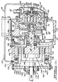
- Figure 1 is a vertical cross-section of an open drive horizontal scroll machine incorporating the unique drive system in accordance with the present invention.
- Figure 2 is a vertical cross-section of an open drive horizontal scroll machine incorporating the unique drive system in accordance with another embodiment of the present invention.
- Compressor 10 comprises a compressor body 12, a cap assembly 14, a main bearing housing 16, an oil pump assembly 18, a lower bearing assembly 20, an orbiting scroll member 22, a non-orbiting scroll member 24 and a two speed drive system 26.
- Compressor body 12 is a generally cup shaped member, preferably made from aluminum defining an internal cavity 28 within which is located main bearing housing 16, an internal bore 30 for mating with oil pump assembly 18 and lower bearing assembly 20 and a suction inlet 32 for mating with the refrigeration circuit associated with compressor 10.
- Compressor body 12, cap assembly 14 and lower bearing assembly 20 define a sealed chamber 34 within which scroll members 22 and 24 are disposed.
- Cap assembly 14 comprises an adapter plate 36, a partition 38, a cap 40, a discharge fitting 42 and a temperature probe 44.
- Adapter plate 36 is secured to compressor body 12 using a plurality of bolts 46.
- Partition 38 is welded about its periphery to adapter plate 36 at the same point that cap 40 is welded to partition 38.
- Partition 38 separates chamber 34 into a suction chamber 48 and a discharge chamber 50.
- Discharge fitting 42 extends through cap 40 and provides a discharge gas outlet from discharge chamber 50 to the refrigeration circuit associated with compressor 10.
- Temperature probe 44 extends through cap 40 and partition 38 such that it is located within a discharge recess 52 located within non-orbiting scroll member 24.
- a dynamic discharge valve assembly 54 is located within discharge recess 52 and is retained within recess 52 by a nut threadingly received within recess 52.
- Main bearing housing 16 is press fit into cavity 28 of compressor body 12 and rests against a shoulder 56 formed by cavity 28.
- the surface of main bearing housing 16 opposite to shoulder 56 is provided with a flat thrust bearing surface 58 against which is located orbiting scroll member 22 which has a usual spiral vane or wrap 60.
- Projecting opposite to wrap 60 is a cylindrical hub 62 having a journal bearing in which is rotatively disposed a drive bushing 66.
- An Oldham coupling 70 is also provided positioned between orbiting scroll member 22 and bearing housing 16. Oldham coupling 70 is keyed to orbiting scroll member 22 and non-orbiting scroll member 24 to prevent rotational movement of orbiting scroll member 22.
- Oldham coupling 70 is preferably of the type disclosed in assignee's U.S. Letters Patent 5,320,506 , the disclosure of which is hereby incorporated herein by reference.
- Non-orbiting scroll member 24 is also provided with a wrap 72 positioned in meshing engagement with wrap 60 of orbiting scroll member 22.
- Non-orbiting scroll member 24 has a centrally disposed passage which communicates with discharge recess 52 through discharge valve assembly 54 which is in turn in communication with discharge chamber 50 defined by cap 40 and partition 38.
- An annular recess 76 is also formed in non-orbiting scroll member 24 within which is disposed a seal assembly 78.
- Recesses 52 and 76 and seal assembly 78 cooperate to define axial pressure biasing chambers which receive pressurized fluid being compressed by wraps 60 and 72 so as to exert an axial biasing force on non-orbiting scroll member 24 to thereby urge the tips of respective wraps 60 and 72 into sealing engagement with the opposed end plate surfaces.
- Seal assembly 78 is preferably of the type described in greater detail in U.S. Patent No. 5,156,539 , the disclosure of which is hereby incorporated herein by reference.
- Non-orbiting scroll member 24 is designed to be mounted to bearing housing 16 in a suitable manner such as disclosed in U.S. Patent No. 4,877,382 or U.S. Patent No. 5,102,316 both disclosures of which are hereby incorporated herein by reference.
- a steel drive shaft or crankshaft 80 having an eccentric crank pin at one end thereof is rotatably journalled in a sleeve bearing 84 in main bearing housing 16 and a roller bearing 86 in lower bearing assembly 20.
- the crank pin is drivingly disposed within the inner bore of drive bushing 66.
- the crank pin has a flat on one surface which drivingly engages a flat surface (not shown) formed in a portion of the bore of drive bushing 66 to provide a radially compliant drive arrangement, such as shown in assignee's aforementioned U.S. Letters Patent 4,877,382.
- Crankshaft 80 includes an axially extending bore which intersects with a radial inlet bore and a radial outlet bore.
- the end of crankshaft 80 opposite to the crank pin extends through lower bearing assembly 20 and is adapted to be connected to two speed drives system 26 which is being used to power crank shaft 80.
- Oil pump assembly 18 is disposed within chamber 34 in concentric relationship to drive shaft 80.
- Oil pump assembly 18 comprises a housing, a pump body, a drive member and a plurality of vanes.
- the housing is secured to compressor body 12 using a plurality of bolts.
- the housing defines an oil inlet passage and an oil outlet passage.
- the pump body is secured to the housing using a plurality of bolts and thus the pump body is stationary.
- the pump body defines a pumping chamber within which the plurality of vanes are located.
- the drive member is drivingly secured to the drive shaft 80 such that rotation of drive shaft 80 causes rotation of the drive member.
- Rotation of drive shaft 80 causes rotation of the drive member which in turn causes rotation of the plurality or vanes in the pumping chamber and the pumping of oil between the inlet passage which is in communication with a supply passage which extends through compressor body 12 and which is in communication with an oil sump 102 located within sealed chamber 34 through a filter.
- the outlet passage is in communication with a supply passage which extends through compressor body 12 and is in communication with a filter chamber 106 formed by compressor body 12.
- An oil filter 108 is disposed within chamber 106 and chamber 106 is closed by a filter cap 110 which is secure to compressor body 12 using a plurality of bolts. Oil filter 108 is located between the supply passage and a return passage which leads back to oil sump 102.
- a spring 112 biases oil filter 108 away from filter cap 110 to ensure oil flows through filter 108 before entering the return passage.
- the return passage is a stepped diameter passage which restricts oil flow to increase the oil pressure thereby providing oil to the moving components of compressor 10.
- Lower bearing assembly 20 comprises roller bearing 86 and a snap ring 114.
- Roller bearing 86 is disposed between drive shaft 80 and the housing of oil pump assembly 18 and snap ring 114 positions bearing 86 against a shoulder on drive shaft 80.
- a bearing spacer and a Belville spring are positioned between two speed drive system 26 and the outer race of bearing 86 to properly locate bearing 86.
- Two speed drive system 26 comprises a planetary gear set 120, a clutch assembly 122 and an end cap assembly 124.
- Planetary gear set 120 comprises a sun gear 130, a plurality of planet gears 132 and a ring gear 134.
- Sun gear 130 is attached to drive shaft 80.
- the plurality of planet gears 132 are meshed with sun gear 130 and are attached to an input shaft 136.
- Input shaft 136 extends through end cap assembly 124 and provides for the driving input to power two speed drive system 26 and thus drive shaft 80.
- a one-way clutch 138 is disposed between input shaft 136 and sun gear 130.
- One-way clutch 138 allows sun gear 130 to rotate faster than input shaft 136 but will provide driving power from input shaft 136 to sun gear 130 when necessary as detailed below.
- Ring gear 134 is in mesh with the plurality of planet gears 132 and is rotatably disposed within compressor body 12.
- Clutch assembly 122 comprises a clutch housing 140, a piston 142 a biasing member on spring 144 and a clutch plate 146.
- Clutch housing 140 is attached to compressor body 12 and is thus prohibited from rotation with respect to compressor body 12.
- Piston 142 and compressor body 12 define a chamber 148.
- An inlet port 150 extends through compressor body 12 to provide communication with chamber 148.
- a fluid pressure line 152 extends between inlet port 150 and discharge chamber 50.
- a solenoid valve 154 controls the flow of pressurized fluid through fluid pressure line 152.
- solenoid valve 154 When low speed operation for two speed drive system 26 of compressor 10 is desired, solenoid valve 154 is activated to place chamber 148 in communication with discharge chamber 50 through pressure line 152 and inlet port 150. Pressurize fluid within chamber 148 reacts against piston 142 to move piston 142 to the left as shown in Figure 1 to release ring gear 134 for rotation.
- input power drives one member, the second member is driven to provide the output and the third member is fixed. If the third member is not fixed, no power is delivered.
- One-way clutch 138 is incorporated to provide low speed operation of two speed drive system 26.
- solenoid valve 154 When solenoid valve 154 is energized and chamber 148 is pressurized, clutch assembly 122 releases ring gear 134 for rotation.
- Sun gear 130 is no longer powered by planet gears 132 and thus sun gear 130 will begin to slow down. Sun gear 130 will slow down until one-way clutch 138 engages thus equalizing the speed between input shaft 136 and sun gear 130 resulting in a one-to-one or low speed rotation for two speed drive system 26.
- pressurized fluid within chamber 148 is released into sealed chamber 34 by solenoid valve 154.
- the release of pressurized fluid from chamber 148 causes springs 144 to again move piston 142 to the right as shown in Figure 1 engaging clutch assembly 122 to place two-speed drive system 26 in its high-speed condition.
- Sealed chamber 34 is closed by an end cover assembly 160 which comprises a cover plate 162 and a bearing cover 164.
- Bearing cover 164 defines an internal chamber 166 having a plurality of circumferentially spaced radially extending ribs which position a spacer 168 and a plurality of seals 170 between input shaft 136 and bearing cover 164.
- Input shaft 136 extends through bearing cover 164 and is adapted for connection to an external power supply by methods known well in the art.
- an open drive horizontal scroll compressor which incorporates a unique two-speed drive system in accordance with another embodiment of the present invention is illustrated and is designated generally by the reference numeral 210.
- Compressor 210 is the same as compressor 10 except that clutch assembly 122 has been replaced by clutch assembly or solenoid valve assembly 222.
- Solenoid valve assembly 222 comprises a solenoid core 224, a solenoid coil 226 and clutch plate 146.
- solenoid coil 226 is energized, thus attracting clutch plate 146 and locking it to solenoid core 224. In this locked position, rotation of ring gear 134 is prohibited. With ring gear 134 locked, power from input shaft 136 is provided to planet gears 132 which results in an increase in speed for sun gear 130. The increase in speed for sun gear 130 is facilitated by the incorporation of one-way clutch 138 which permits the faster rotation of sun gear 130. Sun gear 130 is attached to drive shaft 80 for powering compressor 210. Thus, when solenoid coil 226 is energized, planetary gear set 120 increases the speed between input shaft 136 and drive shaft 80 to provide a high-speed capability for two speed drive system 26. The amount of speed increase between input shaft 136 and drive shaft 80 will be determined by the diameter of ring gear 134 and the diameter of sun gear 130.
- solenoid coil 226 is de-energized which results in disengaging solenoid core 224 from clutch plate 146 which allows rotation of ring gear 134.
- input power drives one member, the second member is provided to the output and the third member is fixed. If the third member is not fixed, no power is delivered.
- One-way clutch 138 is incorporated to provide low speed operation of two speed drive system 26.
- solenoid coil 226 is de-energized, clutch assembly or solenoid valve 222 releases ring gear 134 for rotation.
- Sun gear 130 is no longer powered by planet gears 132 and thus, sun gear 130 will begin to slow down. Sun gear 130 will slow down until one-way clutch 138 engages, thus equalizing the speed between input shaft 136 and sun gear 130 resulting in a one-to-one or low speed rotation for two-speed drive system 26.
- solenoid coil 226 can be energized again to engage clutch plate 146 with solenoid core 224 to plate two-speed drive system 26 in its high-speed condition.
- Two-speed drive system 26 with clutch assembly 122 or solenoid valve assembly 222 can be utilized to drive any other type of open-drive positive displacement compressor. While two-speed drive system 26 with clutch assembly 122 on solenoid valve assembly 222 have been illustrated as being located within sealed chamber 34, it is within the scope of the present invention to mount two-speed drive system 26 external to the compressor or sealed chamber 34. When mounted externally to the compressor or sealed chamber 34, two-speed drive system 26 can be packaged together with a drive pulley and the drive pulley clutch.
- two-speed drive system 26 is illustrated in use with a horizontal compressor, it can be integrated into a vertical hermetic compressor, if desired.
- two-speed drive system 26 is positioned between the motor rotor and the lower bearing.
- the sun gear is attached to the crankshaft, the rotor of the motor has bearings so it can rotate on the compressor shaft with the speed differential being between the crankshaft and the rotor.
- the rotor would then drive the planetary gear housing assembly.
Landscapes
- Engineering & Computer Science (AREA)
- Mechanical Engineering (AREA)
- General Engineering & Computer Science (AREA)
- Applications Or Details Of Rotary Compressors (AREA)
- Rotary Pumps (AREA)
- Structure Of Transmissions (AREA)
Applications Claiming Priority (1)
| Application Number | Priority Date | Filing Date | Title |
|---|---|---|---|
| US11/130,347 US7841845B2 (en) | 2005-05-16 | 2005-05-16 | Open drive scroll machine |
Publications (2)
| Publication Number | Publication Date |
|---|---|
| EP1724468A2 true EP1724468A2 (de) | 2006-11-22 |
| EP1724468A3 EP1724468A3 (de) | 2013-08-14 |
Family
ID=36754238
Family Applications (1)
| Application Number | Title | Priority Date | Filing Date |
|---|---|---|---|
| EP05255573.7A Withdrawn EP1724468A3 (de) | 2005-05-16 | 2005-09-12 | Spiralverdichter mit zwei Geschwindigkeiten |
Country Status (7)
| Country | Link |
|---|---|
| US (1) | US7841845B2 (de) |
| EP (1) | EP1724468A3 (de) |
| KR (1) | KR101215898B1 (de) |
| CN (1) | CN1865706B (de) |
| AU (1) | AU2005234721A1 (de) |
| BR (1) | BRPI0504261A (de) |
| TW (1) | TWI422744B (de) |
Cited By (1)
| Publication number | Priority date | Publication date | Assignee | Title |
|---|---|---|---|---|
| EP3339645A1 (de) * | 2016-12-20 | 2018-06-27 | Mitsubishi Heavy Industries Thermal Systems, Ltd. | Hermetischer elektrischer verdichter und kühlkreislauf damit |
Families Citing this family (9)
| Publication number | Priority date | Publication date | Assignee | Title |
|---|---|---|---|---|
| JP4837331B2 (ja) * | 2005-08-11 | 2011-12-14 | 三菱電機株式会社 | スクロール流体機械の位置決め方法およびその装置、並びにスクロール流体機械の組み立て方法およびその装置 |
| FR2916813B1 (fr) * | 2007-05-29 | 2013-02-08 | Danfoss Commercial Compressors | Compresseur frigorifique a spirales a vitesse variable |
| JP5477113B2 (ja) * | 2010-03-31 | 2014-04-23 | 株式会社豊田自動織機 | 変速機付き圧縮機 |
| US9909586B2 (en) * | 2012-03-23 | 2018-03-06 | Bitzer Kuehlmaschinenbau Gmbh | Crankshaft with aligned drive and counterweight locating features |
| CN104949393A (zh) * | 2015-07-16 | 2015-09-30 | 上海威乐汽车空调器有限公司 | 一种热泵系统用涡旋压缩机 |
| CN107842501A (zh) * | 2016-09-21 | 2018-03-27 | 比亚迪股份有限公司 | 压缩机 |
| US11118514B2 (en) * | 2019-08-09 | 2021-09-14 | Hamilton Sundstrand Corporation | Turbomachine dual spool transmission systems |
| US11713720B2 (en) | 2019-08-09 | 2023-08-01 | Hamilton Sundstrand Corporation | Turbomachine dual spool transmission systems |
| CN116677602A (zh) * | 2023-07-26 | 2023-09-01 | 桂林电子科技大学 | 一种涡旋式空气悬架压缩机 |
Citations (4)
| Publication number | Priority date | Publication date | Assignee | Title |
|---|---|---|---|---|
| US4877382A (en) | 1986-08-22 | 1989-10-31 | Copeland Corporation | Scroll-type machine with axially compliant mounting |
| US5102316A (en) | 1986-08-22 | 1992-04-07 | Copeland Corporation | Non-orbiting scroll mounting arrangements for a scroll machine |
| US5156539A (en) | 1990-10-01 | 1992-10-20 | Copeland Corporation | Scroll machine with floating seal |
| US5320506A (en) | 1990-10-01 | 1994-06-14 | Copeland Corporation | Oldham coupling for scroll compressor |
Family Cites Families (143)
| Publication number | Priority date | Publication date | Assignee | Title |
|---|---|---|---|---|
| US1738645A (en) * | 1918-08-17 | 1929-12-10 | Sullivan Machinery Co | Rotary fluid-pressure motor |
| US2059830A (en) | 1935-09-05 | 1936-11-03 | Gen Electric | Variable speed dual drive |
| US2669098A (en) | 1950-01-03 | 1954-02-16 | Charles J Buell | Refrigerating system for trucks |
| US2725825A (en) | 1954-03-05 | 1955-12-06 | Yeomans Brothers Co | Liquid handling system |
| US2925723A (en) | 1955-03-31 | 1960-02-23 | Union Stock Yard & Transit Co Chicago | Turbo-refrigeration device |
| US2992769A (en) * | 1957-03-20 | 1961-07-18 | Petty Lab Inc | Rotary fluid compressors |
| NL277904A (de) | 1961-05-03 | |||
| US3211365A (en) | 1961-10-16 | 1965-10-12 | Copeland Refrigeration Corp | Compressor structure |
| DE1288615B (de) | 1963-03-27 | 1969-02-06 | Dubinsky Moisei G | Vorrichtung zur Kuehlung einer Kammer |
| US3279683A (en) | 1964-09-21 | 1966-10-18 | American Motors Corp | Motor-compressor unit |
| US3285504A (en) | 1964-12-10 | 1966-11-15 | Gen Motors Corp | Refrigerant apparatus |
| US3494145A (en) | 1968-06-10 | 1970-02-10 | Worthington Corp | Integral turbo compressor-expander system for refrigeration |
| US3924977A (en) | 1973-06-11 | 1975-12-09 | Little Inc A | Positive fluid displacement apparatus |
| US3908396A (en) | 1973-06-20 | 1975-09-30 | Carter James B Ltd | Direct cycle heating, cooling and refrigerating apparatus |
| US4431356A (en) | 1974-11-14 | 1984-02-14 | Lassota Marek J | Hermetic refrigeration rotary motor-compressor |
| US4015438A (en) | 1975-08-29 | 1977-04-05 | The Garrett Corporation | Air cycle air conditioning system for vehicles |
| US4137021A (en) | 1976-02-19 | 1979-01-30 | Lassota Marek J | Rotary compressor and process of compressing compressible fluids |
| US4137006A (en) | 1977-01-26 | 1979-01-30 | K B Southern, Inc. | Composite horizontally split casing |
| EP0005327A1 (de) * | 1978-04-19 | 1979-11-14 | CompAir Industrial Limited | Zahnradtriebwerk zum Antreiben eines Schraubenkompressors mit Mitteln zur Drehzahländerung |
| US4206596A (en) * | 1978-09-14 | 1980-06-10 | General Motors Corporation | Dual shaft gasifier spool for two shaft gas turbine engine |
| US4305192A (en) | 1978-09-27 | 1981-12-15 | Becker John H | Method of fabricating a composite horizontally split casing |
| EP0010930B1 (de) | 1978-10-30 | 1983-09-21 | Sanden Corporation | Kompressoren des Exzenterspiraltyps |
| JPS55109793A (en) | 1979-02-17 | 1980-08-23 | Sanden Corp | Displacement type fluid compressor |
| US4293281A (en) | 1979-04-13 | 1981-10-06 | Lamoreaux Charles L | Mobile air charging system |
| US4260402A (en) | 1979-05-17 | 1981-04-07 | Ingersoll-Rand Company | Housing means for defining air/oil separator and oil reservoir assembly |
| JPS6022199B2 (ja) | 1981-03-09 | 1985-05-31 | サンデン株式会社 | スクロ−ル型圧縮機 |
| JPS5862396A (ja) | 1981-10-12 | 1983-04-13 | Sanden Corp | 流体装置 |
| JPS58117376A (ja) * | 1981-12-29 | 1983-07-12 | Mitsubishi Heavy Ind Ltd | スクロ−ル型流体機械 |
| JPS5952193U (ja) | 1982-09-30 | 1984-04-05 | サンデン株式会社 | スクロ−ル型圧縮機 |
| US4551065A (en) | 1982-12-13 | 1985-11-05 | Becker John H | Composite horizontally or vertically split casing with variable casing ends |
| CA1226478A (en) | 1983-03-15 | 1987-09-08 | Sanden Corporation | Lubricating mechanism for scroll-type fluid displacement apparatus |
| JPH0631625B2 (ja) | 1984-05-25 | 1994-04-27 | 株式会社日立製作所 | スクロ−ル流体機械 |
| US4575319A (en) | 1984-08-01 | 1986-03-11 | Sanden Corporation | Method and apparatus for adjusting the angular relationship of spiral elements in a scroll type fluid displacement apparatus |
| CN1007545B (zh) * | 1985-08-24 | 1990-04-11 | 沈培基 | 摆线等距线齿轮传动副及其装置 |
| US4800782A (en) * | 1985-12-17 | 1989-01-31 | G.E. Machine Tool Limited | Accessory transmission |
| EP0429146B1 (de) | 1986-04-28 | 1993-12-08 | Sanden Corporation | Spiralteil für Spiralverdrängungsmaschine für Fluida |
| US4900238A (en) | 1987-03-20 | 1990-02-13 | Sanden Corporation | Scroll type compressor with releasably secured hermetic housing |
| JPS63158594U (de) | 1987-04-04 | 1988-10-18 | ||
| US5052096A (en) | 1988-09-23 | 1991-10-01 | Carrier Corporation | Grommet insertion method and apparatus |
| US5139256A (en) * | 1988-11-04 | 1992-08-18 | Logan Kenneth A | Ball game and net therefor |
| JPH0788822B2 (ja) | 1989-04-20 | 1995-09-27 | 株式会社日立製作所 | オイルフリー式スクロール形流体機械 |
| JP2816210B2 (ja) | 1989-12-04 | 1998-10-27 | 株式会社日立製作所 | スクロール圧縮機の給油装置 |
| US5137437A (en) | 1990-01-08 | 1992-08-11 | Hitachi, Ltd. | Scroll compressor with improved bearing |
| EP0482209B1 (de) | 1990-05-11 | 1995-11-02 | Sanyo Electric Co., Ltd | Spiralverdichter |
| US5290160A (en) | 1990-09-03 | 1994-03-01 | Mitsubishi Jukogyo Kabushiki Kaisha | Scroll type fluid machinery and assembling method of the same |
| JPH04339189A (ja) | 1991-05-15 | 1992-11-26 | Sanden Corp | スクロール型流体装置 |
| JP2596301Y2 (ja) | 1991-06-28 | 1999-06-14 | サンデン株式会社 | 流体圧縮機 |
| DE69205517T2 (de) | 1991-07-31 | 1996-04-18 | Sanden Corp | Ölzufuhrsystem für eine Spiralmaschine in horizonaler Bauweise. |
| US5172753A (en) | 1991-10-15 | 1992-12-22 | General Motors Corporation | Automobile heating system |
| JP3078369B2 (ja) | 1991-10-24 | 2000-08-21 | サンデン株式会社 | 圧縮機 |
| JPH05133375A (ja) | 1991-11-14 | 1993-05-28 | Matsushita Electric Ind Co Ltd | 電動圧縮機 |
| US5199280A (en) | 1991-11-25 | 1993-04-06 | American Standard Inc. | Co-rotational scroll compressor supercharger device |
| US5354184A (en) | 1992-02-20 | 1994-10-11 | Arthur D. Little, Inc. | Windage loss reduction arrangement for scroll fluid device |
| US5222885A (en) | 1992-05-12 | 1993-06-29 | Tecumseh Products Company | Horizontal rotary compressor oiling system |
| JP2895320B2 (ja) | 1992-06-12 | 1999-05-24 | 三菱重工業株式会社 | 横型密閉圧縮機 |
| US5447415A (en) | 1992-06-29 | 1995-09-05 | Sanden Corporation | Motor driven fluid compressor within hermetic housing |
| US5360319A (en) * | 1993-05-17 | 1994-11-01 | General Motors Corporation | Compressor assembly having control valve for triggered pressure actuated clutch |
| US5346376A (en) | 1993-08-20 | 1994-09-13 | General Motors Corporation | Axial thrust applying structure for the scrolls of a scroll type compressor |
| TW326243U (en) | 1993-09-02 | 1998-02-01 | Toyoda Automatic Loom Works | Scroll type compressor |
| JPH07109983A (ja) | 1993-10-13 | 1995-04-25 | Nippondenso Co Ltd | スクロール型圧縮機 |
| JP3260518B2 (ja) | 1993-11-04 | 2002-02-25 | 松下電器産業株式会社 | スクロール圧縮機及びその組立方法 |
| JPH07133768A (ja) | 1993-11-10 | 1995-05-23 | Toyota Autom Loom Works Ltd | スクロール型圧縮機 |
| JP3014909B2 (ja) | 1993-12-27 | 2000-02-28 | 株式会社デンソー | スクロール型圧縮機 |
| JPH0874753A (ja) | 1994-09-01 | 1996-03-19 | Mitsubishi Heavy Ind Ltd | スクロール型圧縮機 |
| US5678986A (en) | 1994-10-27 | 1997-10-21 | Sanden Corporation | Fluid displacement apparatus with lubricating mechanism |
| JP2956509B2 (ja) | 1995-01-17 | 1999-10-04 | 松下電器産業株式会社 | スクロール気体圧縮機 |
| US5535601A (en) | 1995-02-17 | 1996-07-16 | Tochigi Fugi Sangyo Kabushiki Kaisha | Air conditioning system |
| US5807089A (en) | 1995-06-09 | 1998-09-15 | Nippondenso Co., Ltd. | Scroll type compressor with a reinforced rotation preventing means |
| US5683236A (en) | 1996-03-21 | 1997-11-04 | Alliance Compressors | Anti-reverse rotation valve for scroll compressor |
| US6234769B1 (en) | 1997-07-09 | 2001-05-22 | Denso Corporation | Hybrid type compressor driven by engine and electric motor |
| US6139256A (en) | 1997-08-06 | 2000-10-31 | Solar Turbines Incorporated | Apparatus for controlling the concentricity of a member with a centering device |
| US6129531A (en) | 1997-12-22 | 2000-10-10 | Copeland Corporation | Open drive scroll machine |
| US7083397B1 (en) * | 1998-06-04 | 2006-08-01 | Scroll Technologies | Scroll compressor with motor control for capacity modulation |
| JPH11351175A (ja) | 1998-06-08 | 1999-12-21 | Denso Corp | 電動圧縮機 |
| JP2000087882A (ja) | 1998-09-11 | 2000-03-28 | Sanden Corp | スクロール型圧縮機 |
| JP2000130323A (ja) | 1998-10-29 | 2000-05-12 | Zexel Corp | ハイブリッドコンプレッサ |
| US6358349B1 (en) | 1999-07-01 | 2002-03-19 | Eagle-Picher Industries, Inc. | Method to improve adhesion between pre-cured elastomer and metal surface |
| US6315536B1 (en) | 1999-11-18 | 2001-11-13 | Copeland Corporation | Suction inlet screen and funnel for a compressor |
| JP4729773B2 (ja) | 1999-12-06 | 2011-07-20 | ダイキン工業株式会社 | スクロール型圧縮機 |
| JP2001280249A (ja) | 2000-03-31 | 2001-10-10 | Matsushita Electric Ind Co Ltd | 圧縮機および電動機 |
| JP2002188566A (ja) | 2000-10-10 | 2002-07-05 | Toyota Industries Corp | 圧縮機における冷却構造 |
| US6354821B1 (en) * | 2000-11-22 | 2002-03-12 | Scroll Technologies | Scroll compressor with dual clutch capacity modulation |
| JP2002180980A (ja) | 2000-12-08 | 2002-06-26 | Sanden Corp | スクロール型圧縮機 |
| JP2002362141A (ja) | 2001-01-09 | 2002-12-18 | Toyota Industries Corp | 車両用空調装置 |
| JP2002213377A (ja) | 2001-01-19 | 2002-07-31 | Toyota Industries Corp | スクロール型圧縮機,スクロールおよびその製造方法 |
| JP2002221170A (ja) | 2001-01-25 | 2002-08-09 | Toyota Industries Corp | スクロール圧縮機 |
| JP2003056461A (ja) | 2001-02-15 | 2003-02-26 | Denso Corp | 圧縮機の複合駆動システム |
| JP2002257063A (ja) | 2001-02-28 | 2002-09-11 | Sanden Corp | スクロール型圧縮機 |
| JP4777541B2 (ja) | 2001-06-08 | 2011-09-21 | パナソニック株式会社 | 電動機内蔵の圧縮機と、これを搭載した移動車 |
| JP2003021060A (ja) | 2001-07-10 | 2003-01-24 | Toyota Industries Corp | 圧縮機、圧縮機のバランス取り方法及び治具 |
| JP2003035261A (ja) | 2001-07-19 | 2003-02-07 | Toyota Industries Corp | 圧縮機 |
| US6659727B2 (en) | 2001-09-07 | 2003-12-09 | General Motors Corporation | Control method for a dual mode compressor drive system |
| JP4044341B2 (ja) | 2001-09-14 | 2008-02-06 | サンデン株式会社 | ハイブリッド圧縮機 |
| JP2003097438A (ja) | 2001-09-19 | 2003-04-03 | Toyota Industries Corp | ハイブリッド圧縮機におけるモータ配線の取出し構造 |
| US6685437B2 (en) * | 2001-09-21 | 2004-02-03 | Borgwarner, Inc. | Hydraulic transmission pump assembly having a differential actuation and integrated line pressure control |
| JP3854119B2 (ja) | 2001-10-09 | 2006-12-06 | 株式会社デンソー | 圧縮機制御装置 |
| US6572352B2 (en) | 2001-10-16 | 2003-06-03 | Copeland Corporation | Two-piece powdered metal suction fitting |
| US6742350B2 (en) | 2001-11-03 | 2004-06-01 | Nippon Soken, Inc. | Hybrid compressor device |
| US6644932B2 (en) | 2001-11-15 | 2003-11-11 | Visteon Global Technologies, Inc. | Hybrid electric/mechanical compressor with gear reducer |
| JP2003166467A (ja) | 2001-11-29 | 2003-06-13 | Toyota Industries Corp | 車両用回転機械 |
| JP3935006B2 (ja) | 2001-12-03 | 2007-06-20 | 松下エコシステムズ株式会社 | 発電装置 |
| US6638027B2 (en) | 2001-12-11 | 2003-10-28 | Visteon Global Technologies, Inc. | Hybrid compressor with bearing clutch assembly |
| JP3855866B2 (ja) | 2001-12-26 | 2006-12-13 | 株式会社デンソー | ハイブリッドコンプレッサ装置 |
| US6644933B2 (en) | 2002-01-02 | 2003-11-11 | Borgwarner, Inc. | Water pump with electronically controlled viscous coupling drive |
| JP3700650B2 (ja) | 2002-01-15 | 2005-09-28 | 株式会社デンソー | ハイブリッドコンプレッサおよびハイブリッドコンプレッサ装置 |
| US6761037B2 (en) | 2002-01-23 | 2004-07-13 | Sanden Corporation | Vehicle air conditioner using a hybrid compressor |
| JP4230785B2 (ja) | 2002-01-25 | 2009-02-25 | カルソニックコンプレッサー株式会社 | 気体圧縮機 |
| US6715995B2 (en) | 2002-01-31 | 2004-04-06 | Visteon Global Technologies, Inc. | Hybrid compressor control method |
| AU2003200332B2 (en) | 2002-02-08 | 2005-11-17 | Sanden Corporation | Hybrid compressor |
| JP3933492B2 (ja) | 2002-02-19 | 2007-06-20 | サンデン株式会社 | スクロール型圧縮機 |
| JP2003341352A (ja) | 2002-05-29 | 2003-12-03 | Toyota Industries Corp | ハイブリッドコンプレッサシステム |
| JP3955504B2 (ja) | 2002-06-27 | 2007-08-08 | サンデン株式会社 | 車両空調装置用ハイブリッド圧縮機の起動方法 |
| JP4526755B2 (ja) | 2002-06-27 | 2010-08-18 | サンデン株式会社 | 車両用空調装置 |
| JP4114420B2 (ja) | 2002-07-12 | 2008-07-09 | 株式会社デンソー | ハイブリッドコンプレッサ及びその制御装置 |
| JP4156955B2 (ja) | 2002-09-19 | 2008-09-24 | サンデン株式会社 | 車両空調装置用ハイブリッド圧縮機の駆動方法 |
| JP2004156532A (ja) | 2002-11-06 | 2004-06-03 | Toyota Industries Corp | スクロールコンプレッサにおける容量可変機構 |
| JP4012061B2 (ja) * | 2002-12-26 | 2007-11-21 | キヤノン株式会社 | 画像形成装置、シート処理装置、及び画像形成システム |
| EP1443201B1 (de) | 2003-01-28 | 2016-03-23 | Denso Corporation | Fluidmaschine betreibbar wie eine Pumpe oder ein Motor mit Abwärmerückgewinnungssystem |
| JP2004270614A (ja) | 2003-03-11 | 2004-09-30 | Sanden Corp | 電動圧縮機 |
| JP2004278316A (ja) | 2003-03-12 | 2004-10-07 | Toyota Industries Corp | ハイブリッドコンプレッサの制御装置 |
| JP3919686B2 (ja) | 2003-03-14 | 2007-05-30 | サンデン株式会社 | ハイブリッド圧縮機 |
| JP2004301054A (ja) | 2003-03-31 | 2004-10-28 | Toyota Industries Corp | ハイブリッドコンプレッサ |
| JP2004324591A (ja) | 2003-04-25 | 2004-11-18 | Toyota Industries Corp | ハイブリッドコンプレッサ |
| JP4039320B2 (ja) | 2003-06-17 | 2008-01-30 | 株式会社デンソー | 流体機械 |
| US7201567B2 (en) | 2003-06-20 | 2007-04-10 | Emerson Climate Technologies, Inc. | Plural compressors |
| US20050025650A1 (en) | 2003-07-29 | 2005-02-03 | David Hsia | Method for fabricating a semi-hermetic scroll compressor and its structure |
| JP2005048598A (ja) * | 2003-07-29 | 2005-02-24 | Toyota Industries Corp | 圧縮/膨張機 |
| JP4070701B2 (ja) | 2003-10-07 | 2008-04-02 | 株式会社デンソー | ハイブリッドコンプレッサ装置 |
| US6884047B1 (en) | 2003-10-20 | 2005-04-26 | Varian, Inc. | Compact scroll pump |
| JP4219262B2 (ja) | 2003-12-10 | 2009-02-04 | サンデン株式会社 | 圧縮機 |
| DE102004009073A1 (de) | 2004-02-23 | 2005-09-15 | Behr Gmbh & Co. Kg | Regelbarer Antrieb für ein Kraftfahrzeug |
| JP2005248809A (ja) | 2004-03-03 | 2005-09-15 | Denso Corp | 流体機械 |
| US20050196298A1 (en) | 2004-03-05 | 2005-09-08 | Manning John B. | Gas compressor dual drive mechanism |
| JP4722493B2 (ja) | 2004-03-24 | 2011-07-13 | 株式会社日本自動車部品総合研究所 | 流体機械 |
| JP4070740B2 (ja) | 2004-03-31 | 2008-04-02 | 株式会社デンソー | 流体機械用の切替え弁構造 |
| JP2005291037A (ja) * | 2004-03-31 | 2005-10-20 | Nippon Soken Inc | 流体機械 |
| JP4514493B2 (ja) | 2004-04-02 | 2010-07-28 | サンデン株式会社 | スクロール型流体機械 |
| JP2005307770A (ja) | 2004-04-19 | 2005-11-04 | Anest Iwata Corp | スクロール流体機械 |
| JP2005337189A (ja) | 2004-05-31 | 2005-12-08 | Anest Iwata Corp | スクロール流体機械における旋回スクロールの製造方法 |
| JP2005344548A (ja) | 2004-06-01 | 2005-12-15 | Anest Iwata Corp | スクロール流体機械 |
| JP2005351112A (ja) | 2004-06-08 | 2005-12-22 | Sanden Corp | スクロール圧縮機 |
| US7140851B2 (en) | 2004-09-07 | 2006-11-28 | Chyn Tec. International Co., Ltd. | Axial compliance mechanism of scroll compressor |
| KR100619741B1 (ko) | 2004-09-13 | 2006-09-12 | 엘지전자 주식회사 | 오일토출 저감기능을 구비한 고압식 스크롤 압축기 |
-
2005
- 2005-05-16 US US11/130,347 patent/US7841845B2/en not_active Expired - Fee Related
- 2005-09-09 TW TW094131126A patent/TWI422744B/zh not_active IP Right Cessation
- 2005-09-12 EP EP05255573.7A patent/EP1724468A3/de not_active Withdrawn
- 2005-10-03 BR BRPI0504261-5A patent/BRPI0504261A/pt not_active Application Discontinuation
- 2005-10-13 CN CN2005101135609A patent/CN1865706B/zh not_active Expired - Fee Related
- 2005-10-27 KR KR1020050101730A patent/KR101215898B1/ko not_active Expired - Fee Related
- 2005-11-21 AU AU2005234721A patent/AU2005234721A1/en not_active Abandoned
Patent Citations (4)
| Publication number | Priority date | Publication date | Assignee | Title |
|---|---|---|---|---|
| US4877382A (en) | 1986-08-22 | 1989-10-31 | Copeland Corporation | Scroll-type machine with axially compliant mounting |
| US5102316A (en) | 1986-08-22 | 1992-04-07 | Copeland Corporation | Non-orbiting scroll mounting arrangements for a scroll machine |
| US5156539A (en) | 1990-10-01 | 1992-10-20 | Copeland Corporation | Scroll machine with floating seal |
| US5320506A (en) | 1990-10-01 | 1994-06-14 | Copeland Corporation | Oldham coupling for scroll compressor |
Cited By (1)
| Publication number | Priority date | Publication date | Assignee | Title |
|---|---|---|---|---|
| EP3339645A1 (de) * | 2016-12-20 | 2018-06-27 | Mitsubishi Heavy Industries Thermal Systems, Ltd. | Hermetischer elektrischer verdichter und kühlkreislauf damit |
Also Published As
| Publication number | Publication date |
|---|---|
| US20060257273A1 (en) | 2006-11-16 |
| KR20060118309A (ko) | 2006-11-23 |
| TW200641252A (en) | 2006-12-01 |
| TWI422744B (zh) | 2014-01-11 |
| CN1865706B (zh) | 2012-02-01 |
| US7841845B2 (en) | 2010-11-30 |
| EP1724468A3 (de) | 2013-08-14 |
| KR101215898B1 (ko) | 2012-12-27 |
| CN1865706A (zh) | 2006-11-22 |
| AU2005234721A1 (en) | 2006-11-30 |
| BRPI0504261A (pt) | 2007-01-09 |
Similar Documents
| Publication | Publication Date | Title |
|---|---|---|
| EP1122436B1 (de) | Waagerechter Spiralverdichter | |
| AU2006200256B2 (en) | Scroll machine with single plate floating seal | |
| US5017108A (en) | Scroll compressor with first and second oil pumps in series | |
| US5800141A (en) | Scroll machine with reverse rotation protection | |
| EP0133625A1 (de) | Schmiersystem für einen Rotationskolbenkompressor mit spiralförmigen Eingriffselementen | |
| AU780605B2 (en) | Scroll compressor having a clearance for the oldham coupling | |
| US8747088B2 (en) | Open drive scroll compressor with lubrication system | |
| CN207195176U (zh) | 背压腔结构及具有其的涡旋式压缩机 | |
| US7841845B2 (en) | Open drive scroll machine | |
| US6315536B1 (en) | Suction inlet screen and funnel for a compressor | |
| US6179591B1 (en) | Conical hub bearing for scroll machine | |
| US6129531A (en) | Open drive scroll machine | |
| EP2653649A2 (de) | Spiralverdichter | |
| WO2017163814A1 (ja) | スクロール型圧縮機 | |
| JP5145252B2 (ja) | スクロール圧縮機及びスクロール圧縮機の給油方法 | |
| JP4681322B2 (ja) | スクロール圧縮機 | |
| JP2005201171A (ja) | 圧縮機の潤滑機構 | |
| MXPA05012962A (en) | Open drive scroll machine | |
| JP4024723B2 (ja) | ハイブリッドコンプレッサ | |
| EP0240739B1 (de) | Spiralverdichterschmiersystem | |
| JP2004027983A (ja) | スクロール型圧縮機 | |
| JP2563590B2 (ja) | スクロール圧縮機 | |
| JP2013194596A (ja) | スクロール式膨張機 | |
| JP2021017871A (ja) | 圧縮機 | |
| AU2013203937A1 (en) | Scroll machine with single plate floating seal |
Legal Events
| Date | Code | Title | Description |
|---|---|---|---|
| PUAI | Public reference made under article 153(3) epc to a published international application that has entered the european phase |
Free format text: ORIGINAL CODE: 0009012 |
|
| AK | Designated contracting states |
Kind code of ref document: A2 Designated state(s): AT BE BG CH CY CZ DE DK EE ES FI FR GB GR HU IE IS IT LI LT LU LV MC NL PL PT RO SE SI SK TR |
|
| AX | Request for extension of the european patent |
Extension state: AL BA HR MK YU |
|
| RAP1 | Party data changed (applicant data changed or rights of an application transferred) |
Owner name: EMERSON CLIMATE TECHNOLOGIES, INC. |
|
| PUAL | Search report despatched |
Free format text: ORIGINAL CODE: 0009013 |
|
| AK | Designated contracting states |
Kind code of ref document: A3 Designated state(s): AT BE BG CH CY CZ DE DK EE ES FI FR GB GR HU IE IS IT LI LT LU LV MC NL PL PT RO SE SI SK TR |
|
| AX | Request for extension of the european patent |
Extension state: AL BA HR MK YU |
|
| RIC1 | Information provided on ipc code assigned before grant |
Ipc: F04C 28/08 20060101ALI20130708BHEP Ipc: F04C 18/02 20060101AFI20130708BHEP Ipc: F04C 29/00 20060101ALI20130708BHEP |
|
| AKY | No designation fees paid | ||
| REG | Reference to a national code |
Ref country code: DE Ref legal event code: R108 |
|
| REG | Reference to a national code |
Ref country code: DE Ref legal event code: R108 Effective date: 20140423 |
|
| STAA | Information on the status of an ep patent application or granted ep patent |
Free format text: STATUS: THE APPLICATION IS DEEMED TO BE WITHDRAWN |
|
| 18D | Application deemed to be withdrawn |
Effective date: 20140215 |