US4900238A - Scroll type compressor with releasably secured hermetic housing - Google Patents
Scroll type compressor with releasably secured hermetic housing Download PDFInfo
- Publication number
- US4900238A US4900238A US07/169,983 US16998388A US4900238A US 4900238 A US4900238 A US 4900238A US 16998388 A US16998388 A US 16998388A US 4900238 A US4900238 A US 4900238A
- Authority
- US
- United States
- Prior art keywords
- center block
- shell
- housing
- scroll
- hermetically sealed
- Prior art date
- Legal status (The legal status is an assumption and is not a legal conclusion. Google has not performed a legal analysis and makes no representation as to the accuracy of the status listed.)
- Expired - Lifetime
Links
Images

Classifications
-
- C—CHEMISTRY; METALLURGY
- C23—COATING METALLIC MATERIAL; COATING MATERIAL WITH METALLIC MATERIAL; CHEMICAL SURFACE TREATMENT; DIFFUSION TREATMENT OF METALLIC MATERIAL; COATING BY VACUUM EVAPORATION, BY SPUTTERING, BY ION IMPLANTATION OR BY CHEMICAL VAPOUR DEPOSITION, IN GENERAL; INHIBITING CORROSION OF METALLIC MATERIAL OR INCRUSTATION IN GENERAL
- C23C—COATING METALLIC MATERIAL; COATING MATERIAL WITH METALLIC MATERIAL; SURFACE TREATMENT OF METALLIC MATERIAL BY DIFFUSION INTO THE SURFACE, BY CHEMICAL CONVERSION OR SUBSTITUTION; COATING BY VACUUM EVAPORATION, BY SPUTTERING, BY ION IMPLANTATION OR BY CHEMICAL VAPOUR DEPOSITION, IN GENERAL
- C23C16/00—Chemical coating by decomposition of gaseous compounds, without leaving reaction products of surface material in the coating, i.e. chemical vapour deposition [CVD] processes
- C23C16/04—Coating on selected surface areas, e.g. using masks
-
- C—CHEMISTRY; METALLURGY
- C23—COATING METALLIC MATERIAL; COATING MATERIAL WITH METALLIC MATERIAL; CHEMICAL SURFACE TREATMENT; DIFFUSION TREATMENT OF METALLIC MATERIAL; COATING BY VACUUM EVAPORATION, BY SPUTTERING, BY ION IMPLANTATION OR BY CHEMICAL VAPOUR DEPOSITION, IN GENERAL; INHIBITING CORROSION OF METALLIC MATERIAL OR INCRUSTATION IN GENERAL
- C23C—COATING METALLIC MATERIAL; COATING MATERIAL WITH METALLIC MATERIAL; SURFACE TREATMENT OF METALLIC MATERIAL BY DIFFUSION INTO THE SURFACE, BY CHEMICAL CONVERSION OR SUBSTITUTION; COATING BY VACUUM EVAPORATION, BY SPUTTERING, BY ION IMPLANTATION OR BY CHEMICAL VAPOUR DEPOSITION, IN GENERAL
- C23C16/00—Chemical coating by decomposition of gaseous compounds, without leaving reaction products of surface material in the coating, i.e. chemical vapour deposition [CVD] processes
- C23C16/22—Chemical coating by decomposition of gaseous compounds, without leaving reaction products of surface material in the coating, i.e. chemical vapour deposition [CVD] processes characterised by the deposition of inorganic material, other than metallic material
- C23C16/24—Deposition of silicon only
-
- C—CHEMISTRY; METALLURGY
- C23—COATING METALLIC MATERIAL; COATING MATERIAL WITH METALLIC MATERIAL; CHEMICAL SURFACE TREATMENT; DIFFUSION TREATMENT OF METALLIC MATERIAL; COATING BY VACUUM EVAPORATION, BY SPUTTERING, BY ION IMPLANTATION OR BY CHEMICAL VAPOUR DEPOSITION, IN GENERAL; INHIBITING CORROSION OF METALLIC MATERIAL OR INCRUSTATION IN GENERAL
- C23C—COATING METALLIC MATERIAL; COATING MATERIAL WITH METALLIC MATERIAL; SURFACE TREATMENT OF METALLIC MATERIAL BY DIFFUSION INTO THE SURFACE, BY CHEMICAL CONVERSION OR SUBSTITUTION; COATING BY VACUUM EVAPORATION, BY SPUTTERING, BY ION IMPLANTATION OR BY CHEMICAL VAPOUR DEPOSITION, IN GENERAL
- C23C16/00—Chemical coating by decomposition of gaseous compounds, without leaving reaction products of surface material in the coating, i.e. chemical vapour deposition [CVD] processes
- C23C16/44—Chemical coating by decomposition of gaseous compounds, without leaving reaction products of surface material in the coating, i.e. chemical vapour deposition [CVD] processes characterised by the method of coating
-
- C—CHEMISTRY; METALLURGY
- C30—CRYSTAL GROWTH
- C30B—SINGLE-CRYSTAL GROWTH; UNIDIRECTIONAL SOLIDIFICATION OF EUTECTIC MATERIAL OR UNIDIRECTIONAL DEMIXING OF EUTECTOID MATERIAL; REFINING BY ZONE-MELTING OF MATERIAL; PRODUCTION OF A HOMOGENEOUS POLYCRYSTALLINE MATERIAL WITH DEFINED STRUCTURE; SINGLE CRYSTALS OR HOMOGENEOUS POLYCRYSTALLINE MATERIAL WITH DEFINED STRUCTURE; AFTER-TREATMENT OF SINGLE CRYSTALS OR A HOMOGENEOUS POLYCRYSTALLINE MATERIAL WITH DEFINED STRUCTURE; APPARATUS THEREFOR
- C30B25/00—Single-crystal growth by chemical reaction of reactive gases, e.g. chemical vapour-deposition growth
- C30B25/02—Epitaxial-layer growth
- C30B25/18—Epitaxial-layer growth characterised by the substrate
-
- F—MECHANICAL ENGINEERING; LIGHTING; HEATING; WEAPONS; BLASTING
- F01—MACHINES OR ENGINES IN GENERAL; ENGINE PLANTS IN GENERAL; STEAM ENGINES
- F01C—ROTARY-PISTON OR OSCILLATING-PISTON MACHINES OR ENGINES
- F01C21/00—Component parts, details or accessories not provided for in groups F01C1/00 - F01C20/00
- F01C21/10—Outer members for co-operation with rotary pistons; Casings
-
- F—MECHANICAL ENGINEERING; LIGHTING; HEATING; WEAPONS; BLASTING
- F04—POSITIVE - DISPLACEMENT MACHINES FOR LIQUIDS; PUMPS FOR LIQUIDS OR ELASTIC FLUIDS
- F04C—ROTARY-PISTON, OR OSCILLATING-PISTON, POSITIVE-DISPLACEMENT MACHINES FOR LIQUIDS; ROTARY-PISTON, OR OSCILLATING-PISTON, POSITIVE-DISPLACEMENT PUMPS
- F04C23/00—Combinations of two or more pumps, each being of rotary-piston or oscillating-piston type, specially adapted for elastic fluids; Pumping installations specially adapted for elastic fluids; Multi-stage pumps specially adapted for elastic fluids
- F04C23/008—Hermetic pumps
-
- F—MECHANICAL ENGINEERING; LIGHTING; HEATING; WEAPONS; BLASTING
- F04—POSITIVE - DISPLACEMENT MACHINES FOR LIQUIDS; PUMPS FOR LIQUIDS OR ELASTIC FLUIDS
- F04C—ROTARY-PISTON, OR OSCILLATING-PISTON, POSITIVE-DISPLACEMENT MACHINES FOR LIQUIDS; ROTARY-PISTON, OR OSCILLATING-PISTON, POSITIVE-DISPLACEMENT PUMPS
- F04C2240/00—Components
- F04C2240/60—Shafts
- F04C2240/603—Shafts with internal channels for fluid distribution, e.g. hollow shaft
-
- Y—GENERAL TAGGING OF NEW TECHNOLOGICAL DEVELOPMENTS; GENERAL TAGGING OF CROSS-SECTIONAL TECHNOLOGIES SPANNING OVER SEVERAL SECTIONS OF THE IPC; TECHNICAL SUBJECTS COVERED BY FORMER USPC CROSS-REFERENCE ART COLLECTIONS [XRACs] AND DIGESTS
- Y10—TECHNICAL SUBJECTS COVERED BY FORMER USPC
- Y10S—TECHNICAL SUBJECTS COVERED BY FORMER USPC CROSS-REFERENCE ART COLLECTIONS [XRACs] AND DIGESTS
- Y10S417/00—Pumps
- Y10S417/902—Hermetically sealed motor pump unit
-
- Y—GENERAL TAGGING OF NEW TECHNOLOGICAL DEVELOPMENTS; GENERAL TAGGING OF CROSS-SECTIONAL TECHNOLOGIES SPANNING OVER SEVERAL SECTIONS OF THE IPC; TECHNICAL SUBJECTS COVERED BY FORMER USPC CROSS-REFERENCE ART COLLECTIONS [XRACs] AND DIGESTS
- Y10—TECHNICAL SUBJECTS COVERED BY FORMER USPC
- Y10T—TECHNICAL SUBJECTS COVERED BY FORMER US CLASSIFICATION
- Y10T29/00—Metal working
- Y10T29/49—Method of mechanical manufacture
- Y10T29/49229—Prime mover or fluid pump making
- Y10T29/49236—Fluid pump or compressor making
- Y10T29/4924—Scroll or peristaltic type
-
- Y—GENERAL TAGGING OF NEW TECHNOLOGICAL DEVELOPMENTS; GENERAL TAGGING OF CROSS-SECTIONAL TECHNOLOGIES SPANNING OVER SEVERAL SECTIONS OF THE IPC; TECHNICAL SUBJECTS COVERED BY FORMER USPC CROSS-REFERENCE ART COLLECTIONS [XRACs] AND DIGESTS
- Y10—TECHNICAL SUBJECTS COVERED BY FORMER USPC
- Y10T—TECHNICAL SUBJECTS COVERED BY FORMER US CLASSIFICATION
- Y10T29/00—Metal working
- Y10T29/49—Method of mechanical manufacture
- Y10T29/49718—Repairing
- Y10T29/49721—Repairing with disassembling
Definitions
- This invention relates to a scroll type compressor and more particularly, to a motor driven scroll compressor having the compression and drive mechanisms within a hermetically sealed container.
- Scroll type fluid displacement apparatus are well known in the prior art.
- U.S. Pat. No. 801,182 issued to Creux discloses such an apparatus which includes two scrolls, each having a circular end plate and a spiroidal or involute spiral element.
- the scrolls are maintained angularly and radially offset so that both spiral elements interfit to form a plurality of line contacts between their spiral curved surfaces to thereby seal off and define at least one pair of fluid pockets.
- the relative orbital motion of the two scrolls shifts the line contacts along the spiral curved surfaces and, as a result, the volume of the fluid pockets increases or decreases, dependent on the direction of the orbital motion.
- a scroll type fluid displacement apparatus may be used to compress, expand or pump fluids.
- U.S. Pat. No. 4,560,330 discloses such a hermetic type scroll compressor which includes a fixed scroll, orbiting scroll, rotation preventing device and driving mechanism in one sealed container.
- the essentially inseparable container is sealed by welding or other means so that leakage of refrigerant gas from the container is completely prevented.
- hermetic type scroll compressor prevents leakage of refrigerant gas from the container, this hermetic type scroll compressor can hardly be disassembled and reassembled for inspection, and repair or exchange of parts.
- a hermetic type scroll compressor includes first and second cup shaped casings and a center block therebetween.
- a fixed scroll is fixedly disposed in the first cup shaped casing and has a circular end plate from which a first wrap extends.
- An orbiting scroll has a circular end plate from which a second wrap extends. The first and second wraps interfit at an angular and radial offset to form a plurality of line contacts to define at least one pair of sealed off fluid pockets.
- a rotation preventing device is disposed between the orbiting scroll and the center block which is connected to the first and second cup shaped casings.
- a driving mechanism having a motor driven drive shaft is disposed in the second cup shaped casing and operatively connects to the orbiting scroll to effect the orbital motion of the orbiting scroll by rotation of a drive shaft while rotation of the orbiting scroll is prevented by a rotation preventing device.
- the fluid pockets shift along the spiral curved surfaces of the wraps which change the volume of the fluid pockets.
- the first housing having the first cup shaped casing, fixed scroll, orbiting scroll and rotation preventing device is built on the center block.
- the second housing having the drive shaft, motor and second cup shaped casing is also built on the center block.
- the first cup shaped casing and the second cup shaped casing are releasably and hermetically secured to each other through the center block.
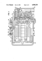
- FIG. 1 is a vertical longitudinal sectional view of a hermetic type scroll compressor in accordance with one embodiment of this invention.
- FIG. 2 is a vertical longitudinal sectional view of a hermetic type scroll compressor in accordance with another embodiment of this invention.
- FIG. 1 depicts a hermetic type scroll refrigerant compressor 1 in accordance with a first embodiment of the present invention.
- Compressor 1 includes first cup shaped casing or shell 10, second cup shaped casing or shell 20 and center block 30 which is attached to first cup shaped casing 10 and second cup shaped casing 20. Opening or bore 31 is formed in the center of center block 30 for receiving drive shaft 11. Radial projection 301 is formed in the inner peripheral surface of opening 31.
- Drive shaft 11 is rotatably supported in opening 31 by bearing 33.
- Bearing 33 firmly fits in opening 31.
- Outer ring 33a of bearing 33 is stopped at a rear end surface of radial projection 301.
- Nut 34 is screwed on drive shaft 11 and faces one end surface of inner ring 33b of bearing 33.
- Flange 111 located at one end of drive shaft 11 faces the other end surface of inner ring 33b of bearing 33. Axial motion of drive shaft 11 is thereby prevented by flange 111 and nut 34. Rotor 40a of motor 40 surrounds drive shaft 11. Rotor 40 a may be firmly inserted over drive shaft 11.
- Fixed scroll 50 includes circular end plate 51 and wrap or spiral elements 52 affixed to or extending from one end surface of end plate 51.
- Fixed scroll 50 is fixed within the inner chamber of first cup shaped casing 10 by screws 11 screwed into end plate 51 from outside of first cup shaped casing 10.
- Seal ring 11b is located between an inner surface of screw flange 11a and the outer end surface of first cup shaped casing 10 to seal the connection therebetween.
- Circular end plate 51 of fixed scroll 50 partitions the inner chamber of first cup shaped casing 10 into two chambers, such as front chamber 18 and rear chamber 19.
- Orbiting scroll 60 is disposed at the rear end side of center block 30 through later mentioned rotation preventing/thrust bearing device 45.
- Orbiting scroll 60 includes circular end plate 61 and wrap or spiral element 62 affixed to or extending from one end surface of circular end plate 61.
- Annular projection 16 is formed opposite the surface of circular end plate 61 from which spiral element 62 extends.
- Bearing 16d is disposed within the inner peripheral wall of the annular projection 16.
- Bushing 115 is attached to one end of drive shaft 11 at a radial offset through pin member 115b. Bushing 115 is inserted into annular projection 16 of orbiting scroll 60. Orbiting scroll 60 is rotatably supported by bushing 115 through bearing 16d placed on the outer peripheral surface of bushing 115.
- Rotation preventing/thrust bearing device 45 is placed between the rear end surface of center block 30 and the end surface of circular end plate 61.
- Rotation preventing/thrust bearing device 45 includes fixed ring 451 attached on the axial end surface of annular projection 302 which is formed in the rear end surface of center block 30, orbiting ring 452 attached on the end surface of circular end plate 61, and a plurality of bearing elements, such as balls 453, placed between pockets 451a, 452a formed by rings 451, 452.
- the rotation of orbiting scroll 60 during orbital motion is prevented by the interaction of balls 453 with rings 451, 452.
- the axial thrust load from orbiting scroll 60 is supported on center block 30 through balls 453. While orbiting scroll 60 orbits, the rotation of orbiting scroll 60 is prevented by rotation preventing/thrust bearing device 45.
- spiral element 62 of orbiting scroll 60 interfits spiral element 52 of fixed scroll 50 at an angular offset of 180° and at a predetermined radial offset.
- Spiral elements 62 and 52 define at least one pair of sealed off fluid pockets between their interfitting surfaces.
- Radial projection 303 formed in the outer peripheral surface of center block 30 is fixed to the axial end surface of first cup shaped casing 10 by screws 12.
- Seal ring 12a is disposed within circumferential groove 12b of annular projection 302 to form a seal between the inner wall of first cup shaped casing 10 and the outer peripheral surface of annular projection 302.
- stator 40b is held firmly between center block 30 and rear bearing unit 70.
- the inner peripheral surface of stator 40b and the outer peripheral surface of rotor 40a face each other.
- Rear bearing unit 70 and motor 40 are covered by second cup shaped casing 20.
- Flange 21a formed at opening end 21 of second cup shaped casing 20 is fixed to radial projection 303 of center block 30 by screws 14.
- Seal ring 14a is disposed within a circular groove 14b of flange 21a to form a seal between the front end surface of radial projection 303 and an axial end surface of flange 21a.
- Terminals 412a are connected to an external electrical source (not shown) through a switch (also not shown).
- Hermetic seal base 412 is insulated from terminals 412a and fixed to projection 413 which is formed on side surface of second cup shaped casing 20 by screws 414. Seal ring 414a is disposed within a circular groove 414b of projection 413 to form a seal between the rear end surface of hermetic seal base 412 and the axial end surface of projection 413.
- the refrigerant gas in the front chamber is taken into the sealed fluid pockets between the fixed scroll and orbiting scroll, then moves toward the center of the spiral wraps during the orbital motion of the orbiting scroll with a resultant volume reduction and compression, and is discharged to rear chamber 19 as through hole 56 and one-way valve 56c. Discharged gas in the rear chamber then flows to an external fluid circuit (not shown) through outlet port 10c.
- hermetic type scroll refrigerant compressor 1 is shown in accordance with another embodiment of the present invention.
- the same construction is accorded like numerals as that shown in FIG. 1.
- the description of that constructions is substantially omitted to simplify the description herein.
- Orbiting scroll 60 interfits fixed scroll 50.
- Annular projection 16 is formed opposite the surface of circular end plate 61 from which spiral element 62 is extended.
- Bearing 16d is disposed within the inner peripheral wall of the annular projection 16.
- a first center block 310 having central opening or bore 311 is disposed adjacent to rotation preventing/thrust bearing device 45.
- the first center block 310 is releasably and hermetically secured to an axial end surface of first cup shaped casing 10 by screws 12.
- Seal ring 12a is disposed within a circumferential groove 12b of annular projection 312 formed at the rear end surface of the center block 310 to form a seal between the inner wall of the first cup shaped casing 10 and the outer peripheral surface of annular projection 312.
- a first housing 100 includes the first center block 310 and the first cup shaped casing 10 having fixed scroll 50, orbiting scroll 60 and rotation preventing/thrust bearing device 45 therein.
- Compression mechanism section 110 comprises a first center block 310 and the construction to the right thereof as shown in FIG. 2.
- Second center block 320 rotatably supports drive shaft 11 in center block central opening or bore 321 through bearing 33.
- One end of drive shaft 11 is rotatably supported by rear bearing unit 70 through bearing 71.
- Stator 40b of motor 40 is held between the second center block 320 and rear bearing unit 70.
- Rear bearing unit 70 is releasably secured to the second center block 320 by screws 13.
- driving mechanism section 120 is to the left of first center block 310 as shown in FIG. 2.
- the second center block 320 is positioned firmly within second cup shaped casing 20 and against ridge 323 formed in the inner wall of the second cup shaped casing 20.
- a second housing 200 includes the driving mechanism section 120 and the second cup shaped casing 20.
- Bushing 115 is attached to one end of drive shaft 11 at a radial offset through pin member 115b.
- the first housing 100 and the second housing 200 are fitted together so that bushing 115 is inserted into annular projection 16 of circular end plate 61.
- Drive shaft 11 is attached to orbiting scroll 60 at a radial offset.
- Flange 21a formed at opening end 21 of second cup shaped casing 20 is releasably and hermetically secured to radial projection 313 of first center block 310 by screws 14 and seal ring 14a.
- Seal ring 14a is disposed within a circular groove 14b of flange 21a to form a seal between the front end surface of radial projection 313 and the axial end surface of flange 21a.
- Annular projection 322 and the recess defined by annular projection or portion 312 form an alignment mechanism for aligning drive shaft 11 with the orbiting scroll when first housing 100 and second housing 200 engage first center block 310.
- compression mechanism section 110 and driving mechanism 120 are fitted together, the facing surfaces of first center block 310 and second center block 320 form an alignment mechanism for aligning drive shaft 11 with orbiting scroll 60.
- Annular projection or portion 312 of first center block 310 includes annular recess 314 formed in an inner wall thereof. With reference to FIG. 2, recess 314 is formed at the front or left end of the inner wall which forms bore 311. Recess 314 includes abutment surface 315 which is substantially normal to the center line of shaft 11 when sections 110 and 120 are joined. Front end surface or guide surface 316 of first center block 310 extends radially outwardly from annular recess 314 for slidingly guiding second center block 320 therealong and toward annular recess 314. As can be seen while viewing FIG. 2, surface 316 is preferably frustoconical.
- Annular projection 322 of second center block 320 has an outer diameter slightly smaller than the diameter of annular recess 314, so that projection 322 may securely interfit with recess 314 when the first and second center blocks are brought into engagement.
- abutment surface 315 prevents annular projection 322, which is formed at the front or right end of second block 320, from penetrating within first cup shaped casing 10 beyond first center block 310.
- the front surface of second block 320 includes portion 324 which extends radially outwardly from annular projection 322.
- Portion 324 is shown as being frustoconical and as having a surface with a slope less than the slope of surface 316 with respect to the center line of shaft 11.
- front end surface 316 may guide or center annular projection 322 into annular recess 314.
- the facing surfaces of the first and second center blocks including projection 322 and annular recess 314 form an alignment mechanism for aligning drive shaft 11 with orbiting scroll 60.
Abstract
Description
Claims (31)
Applications Claiming Priority (4)
| Application Number | Priority Date | Filing Date | Title |
|---|---|---|---|
| JP62-67354 | 1987-03-20 | ||
| JP62067354A JPS63235682A (en) | 1987-03-20 | 1987-03-20 | Scroll type fluid device |
| JP62-67335 | 1987-03-20 | ||
| JP62067335A JP2670442B2 (en) | 1986-03-31 | 1987-03-20 | Crystal formation method |
Related Child Applications (1)
| Application Number | Title | Priority Date | Filing Date |
|---|---|---|---|
| US07/296,596 Continuation-In-Part US4940396A (en) | 1988-01-14 | 1989-01-13 | Hermatic scroll type compressor with two casings and center blocks |
Publications (1)
| Publication Number | Publication Date |
|---|---|
| US4900238A true US4900238A (en) | 1990-02-13 |
Family
ID=26408524
Family Applications (1)
| Application Number | Title | Priority Date | Filing Date |
|---|---|---|---|
| US07/169,983 Expired - Lifetime US4900238A (en) | 1987-03-20 | 1988-03-18 | Scroll type compressor with releasably secured hermetic housing |
Country Status (1)
| Country | Link |
|---|---|
| US (1) | US4900238A (en) |
Cited By (28)
| Publication number | Priority date | Publication date | Assignee | Title |
|---|---|---|---|---|
| US5000669A (en) * | 1987-09-08 | 1991-03-19 | Sanden Corporation | Hermetic scroll type compressor having two section chambers linked by inclined oil passage |
| AU618570B2 (en) * | 1988-01-14 | 1992-01-02 | Sanden Corporation | Hermetic scroll type compressor |
| US5247738A (en) * | 1991-10-24 | 1993-09-28 | Sanden Corporation | Method for assembling motor driven fluid compressor |
| US5249360A (en) * | 1991-07-29 | 1993-10-05 | Westinghouse Air Brake Company | Method of reconditioning valves |
| US5379516A (en) * | 1993-04-06 | 1995-01-10 | Carrier Corporation | Scroll compressor pump cartridge assembly |
| US5431550A (en) * | 1993-09-14 | 1995-07-11 | Sanden Corporation | Hermetic motor driven scroll apparatus having improved lubricating mechanism |
| US5443374A (en) * | 1991-10-24 | 1995-08-22 | Sanden Corporation | Motor driven fluid compressor |
| US5447415A (en) * | 1992-06-29 | 1995-09-05 | Sanden Corporation | Motor driven fluid compressor within hermetic housing |
| US5505595A (en) * | 1993-12-20 | 1996-04-09 | Sanden Corporation | Scroll type fluid displacement apparatus having axial movement regulation of the driving mechanism |
| US5533875A (en) * | 1995-04-07 | 1996-07-09 | American Standard Inc. | Scroll compressor having a frame and open sleeve for controlling gas and lubricant flow |
| US5597296A (en) * | 1994-11-30 | 1997-01-28 | Matsushita Electric Industrial Co., Ltd. | Scroll compressor having a check valve received in a stationary scroll member recess |
| US5678986A (en) * | 1994-10-27 | 1997-10-21 | Sanden Corporation | Fluid displacement apparatus with lubricating mechanism |
| US5857839A (en) * | 1993-08-10 | 1999-01-12 | Sanden Corporation | Compressor having noise and vibration reducing reed valve |
| US6129531A (en) * | 1997-12-22 | 2000-10-10 | Copeland Corporation | Open drive scroll machine |
| US6315536B1 (en) | 1999-11-18 | 2001-11-13 | Copeland Corporation | Suction inlet screen and funnel for a compressor |
| US20030013343A1 (en) * | 2001-06-08 | 2003-01-16 | Matsushita Electric Industrial Co., Ltd. | Compressor with built-in motor and mobile structure using the same |
| US20040179959A1 (en) * | 2003-03-11 | 2004-09-16 | Takehiro Hasegawa | Motor driven compressor |
| US20040208760A1 (en) * | 2003-04-15 | 2004-10-21 | Yap Zer Kai | Terminal block assembly for a hermetic compressor |
| US20050008507A1 (en) * | 2003-07-11 | 2005-01-13 | Skinner Robin G. | Bearing support and stator assembly for compressor |
| US20050129536A1 (en) * | 2003-12-10 | 2005-06-16 | Shinichi Ohtake | Compressor |
| US20050129558A1 (en) * | 2003-12-15 | 2005-06-16 | Matsushita Electric Industrial Co., Ltd. | Electric compressor and assembling method thereof |
| US20050226756A1 (en) * | 2004-04-13 | 2005-10-13 | Sanden Corporation | Compressor |
| US20050265878A1 (en) * | 2004-05-27 | 2005-12-01 | Sanden Corporation | Compressor |
| US20050271534A1 (en) * | 2004-06-08 | 2005-12-08 | Sanden Corporation | Scroll compressor and air-conditioning system for vehicle using the scroll compressor |
| US20060065012A1 (en) * | 2004-09-28 | 2006-03-30 | Sanden Corporation | Compressor |
| US20060257273A1 (en) * | 2005-05-16 | 2006-11-16 | Copeland Corporation | Open drive scroll machine |
| US20110200466A1 (en) * | 2010-02-16 | 2011-08-18 | Visteon Global Technologies, Inc. | Compact Structure For An Electric Compressor |
| EP2719862A1 (en) * | 2011-06-13 | 2014-04-16 | Sanden Corporation | Fluid machine |
Citations (14)
| Publication number | Priority date | Publication date | Assignee | Title |
|---|---|---|---|---|
| US19961A (en) * | 1858-04-13 | Improvement in revolving fire-arms | ||
| US801182A (en) * | 1905-06-26 | 1905-10-03 | Leon Creux | Rotary engine. |
| US1156700A (en) * | 1915-06-28 | 1915-10-12 | Gerald De Courcy May | Cooling and lubricating device for vacuum-pumps. |
| US1934155A (en) * | 1930-06-27 | 1933-11-07 | Frigidaire Corp | Refrigerating apparatus |
| US2178425A (en) * | 1937-02-18 | 1939-10-31 | Gen Electric | Refrigerating machine |
| US3463091A (en) * | 1966-03-23 | 1969-08-26 | Jean Delsuc | Volumetrical pump |
| US4065279A (en) * | 1976-09-13 | 1977-12-27 | Arthur D. Little, Inc. | Scroll-type apparatus with hydrodynamic thrust bearing |
| US4201521A (en) * | 1978-03-20 | 1980-05-06 | Trw Inc. | Pump and motor assembly |
| EP0059925A1 (en) * | 1981-03-03 | 1982-09-15 | Sanden Corporation | Drive mechanism for a scroll type fluid displacement apparatus |
| JPS58172485A (en) * | 1982-04-02 | 1983-10-11 | Hitachi Ltd | Scroll fluid machine |
| US4439118A (en) * | 1980-11-10 | 1984-03-27 | Sanden Corporation | Orbiting fluid displacement apparatus with counterweight attachment |
| US4560330A (en) * | 1983-10-21 | 1985-12-24 | Hitachi, Ltd. | Scroll device with suction chamber pressure relief |
| JPS61116089A (en) * | 1984-11-13 | 1986-06-03 | Nippon Soken Inc | Scroll-type vacuum pump |
| JPS61291793A (en) * | 1985-05-22 | 1986-12-22 | Mitsubishi Electric Corp | Scroll compressor |
-
1988
- 1988-03-18 US US07/169,983 patent/US4900238A/en not_active Expired - Lifetime
Patent Citations (15)
| Publication number | Priority date | Publication date | Assignee | Title |
|---|---|---|---|---|
| US19961A (en) * | 1858-04-13 | Improvement in revolving fire-arms | ||
| US801182A (en) * | 1905-06-26 | 1905-10-03 | Leon Creux | Rotary engine. |
| US1156700A (en) * | 1915-06-28 | 1915-10-12 | Gerald De Courcy May | Cooling and lubricating device for vacuum-pumps. |
| US1934155A (en) * | 1930-06-27 | 1933-11-07 | Frigidaire Corp | Refrigerating apparatus |
| US2178425A (en) * | 1937-02-18 | 1939-10-31 | Gen Electric | Refrigerating machine |
| US3463091A (en) * | 1966-03-23 | 1969-08-26 | Jean Delsuc | Volumetrical pump |
| US4065279A (en) * | 1976-09-13 | 1977-12-27 | Arthur D. Little, Inc. | Scroll-type apparatus with hydrodynamic thrust bearing |
| US4201521A (en) * | 1978-03-20 | 1980-05-06 | Trw Inc. | Pump and motor assembly |
| US4439118A (en) * | 1980-11-10 | 1984-03-27 | Sanden Corporation | Orbiting fluid displacement apparatus with counterweight attachment |
| EP0059925A1 (en) * | 1981-03-03 | 1982-09-15 | Sanden Corporation | Drive mechanism for a scroll type fluid displacement apparatus |
| US4466784A (en) * | 1981-03-03 | 1984-08-21 | Sanden Corporation | Drive mechanism for a scroll type fluid displacement apparatus |
| JPS58172485A (en) * | 1982-04-02 | 1983-10-11 | Hitachi Ltd | Scroll fluid machine |
| US4560330A (en) * | 1983-10-21 | 1985-12-24 | Hitachi, Ltd. | Scroll device with suction chamber pressure relief |
| JPS61116089A (en) * | 1984-11-13 | 1986-06-03 | Nippon Soken Inc | Scroll-type vacuum pump |
| JPS61291793A (en) * | 1985-05-22 | 1986-12-22 | Mitsubishi Electric Corp | Scroll compressor |
Cited By (41)
| Publication number | Priority date | Publication date | Assignee | Title |
|---|---|---|---|---|
| US5000669A (en) * | 1987-09-08 | 1991-03-19 | Sanden Corporation | Hermetic scroll type compressor having two section chambers linked by inclined oil passage |
| AU618570B2 (en) * | 1988-01-14 | 1992-01-02 | Sanden Corporation | Hermetic scroll type compressor |
| US5249360A (en) * | 1991-07-29 | 1993-10-05 | Westinghouse Air Brake Company | Method of reconditioning valves |
| US5247738A (en) * | 1991-10-24 | 1993-09-28 | Sanden Corporation | Method for assembling motor driven fluid compressor |
| AU649890B2 (en) * | 1991-10-24 | 1994-06-02 | Sanden Corporation | Method for assembling motor driven fluid compressor |
| US5443374A (en) * | 1991-10-24 | 1995-08-22 | Sanden Corporation | Motor driven fluid compressor |
| US5447415A (en) * | 1992-06-29 | 1995-09-05 | Sanden Corporation | Motor driven fluid compressor within hermetic housing |
| US5379516A (en) * | 1993-04-06 | 1995-01-10 | Carrier Corporation | Scroll compressor pump cartridge assembly |
| USRE35760E (en) * | 1993-04-06 | 1998-04-07 | Carrier Corporation | Method of making a scroll compressor pump cartridge subassembly |
| US5857839A (en) * | 1993-08-10 | 1999-01-12 | Sanden Corporation | Compressor having noise and vibration reducing reed valve |
| US5431550A (en) * | 1993-09-14 | 1995-07-11 | Sanden Corporation | Hermetic motor driven scroll apparatus having improved lubricating mechanism |
| US5505595A (en) * | 1993-12-20 | 1996-04-09 | Sanden Corporation | Scroll type fluid displacement apparatus having axial movement regulation of the driving mechanism |
| US5678986A (en) * | 1994-10-27 | 1997-10-21 | Sanden Corporation | Fluid displacement apparatus with lubricating mechanism |
| US5597296A (en) * | 1994-11-30 | 1997-01-28 | Matsushita Electric Industrial Co., Ltd. | Scroll compressor having a check valve received in a stationary scroll member recess |
| US5533875A (en) * | 1995-04-07 | 1996-07-09 | American Standard Inc. | Scroll compressor having a frame and open sleeve for controlling gas and lubricant flow |
| US6129531A (en) * | 1997-12-22 | 2000-10-10 | Copeland Corporation | Open drive scroll machine |
| US6315536B1 (en) | 1999-11-18 | 2001-11-13 | Copeland Corporation | Suction inlet screen and funnel for a compressor |
| US20030013343A1 (en) * | 2001-06-08 | 2003-01-16 | Matsushita Electric Industrial Co., Ltd. | Compressor with built-in motor and mobile structure using the same |
| US6866487B2 (en) * | 2001-06-08 | 2005-03-15 | Matsushita Electric Industrial Co., Ltd. | Compressor with built-in motor and mobile structure using the same |
| US20040179959A1 (en) * | 2003-03-11 | 2004-09-16 | Takehiro Hasegawa | Motor driven compressor |
| US7281910B2 (en) * | 2003-03-11 | 2007-10-16 | Sanden Corporation | Motor driven compressor |
| US20040208760A1 (en) * | 2003-04-15 | 2004-10-21 | Yap Zer Kai | Terminal block assembly for a hermetic compressor |
| US20050008507A1 (en) * | 2003-07-11 | 2005-01-13 | Skinner Robin G. | Bearing support and stator assembly for compressor |
| US7063518B2 (en) | 2003-07-11 | 2006-06-20 | Tecumseh Products Company | Bearing support and stator assembly for compressor |
| US7736136B2 (en) | 2003-12-10 | 2010-06-15 | Sanden Corporation | Compressor including separation tube engagement mechanism |
| US20050129536A1 (en) * | 2003-12-10 | 2005-06-16 | Shinichi Ohtake | Compressor |
| US20050129558A1 (en) * | 2003-12-15 | 2005-06-16 | Matsushita Electric Industrial Co., Ltd. | Electric compressor and assembling method thereof |
| US20050226756A1 (en) * | 2004-04-13 | 2005-10-13 | Sanden Corporation | Compressor |
| US7314355B2 (en) | 2004-05-27 | 2008-01-01 | Sanden Corporation | Compressor including deviated separation chamber |
| US20050265878A1 (en) * | 2004-05-27 | 2005-12-01 | Sanden Corporation | Compressor |
| US20050271534A1 (en) * | 2004-06-08 | 2005-12-08 | Sanden Corporation | Scroll compressor and air-conditioning system for vehicle using the scroll compressor |
| US7255543B2 (en) | 2004-06-08 | 2007-08-14 | Sanden Corporation | Scroll compressor and air-conditioning system for vehicle using the scroll compressor |
| US20060065012A1 (en) * | 2004-09-28 | 2006-03-30 | Sanden Corporation | Compressor |
| US7281912B2 (en) | 2004-09-28 | 2007-10-16 | Sanden Corporation | Compressor having a safety device being built in at least one of the screw plugs of the oil-separator |
| US20060257273A1 (en) * | 2005-05-16 | 2006-11-16 | Copeland Corporation | Open drive scroll machine |
| US7841845B2 (en) | 2005-05-16 | 2010-11-30 | Emerson Climate Technologies, Inc. | Open drive scroll machine |
| US20110200466A1 (en) * | 2010-02-16 | 2011-08-18 | Visteon Global Technologies, Inc. | Compact Structure For An Electric Compressor |
| US8974197B2 (en) | 2010-02-16 | 2015-03-10 | Halla Visteon Climate Control Corporation | Compact structure for an electric compressor |
| EP2719862A1 (en) * | 2011-06-13 | 2014-04-16 | Sanden Corporation | Fluid machine |
| EP2719862A4 (en) * | 2011-06-13 | 2015-01-28 | Sanden Corp | Fluid machine |
| US9546656B2 (en) | 2011-06-13 | 2017-01-17 | Sanden Holdings Corporation | Fluid machine |
Similar Documents
| Publication | Publication Date | Title |
|---|---|---|
| US4900238A (en) | Scroll type compressor with releasably secured hermetic housing | |
| US4940396A (en) | Hermatic scroll type compressor with two casings and center blocks | |
| US4990071A (en) | Scroll type fluid apparatus having two orbiting end plates linked together | |
| US4477238A (en) | Scroll type compressor with wrap portions of different axial heights | |
| US4547138A (en) | Lubricating mechanism for scroll-type fluid displacement apparatus | |
| US4626179A (en) | Axial thrust load mechanism for a scroll type fluid displacement apparatus | |
| EP0060496B1 (en) | Axial clearance adjustment mechanism for scroll type fluid displacement apparatus | |
| EP0107409B1 (en) | Scroll type compressor with lubricating system | |
| US5247738A (en) | Method for assembling motor driven fluid compressor | |
| US5779461A (en) | Scroll type fluid displacement apparatus having a control system of line contacts between spiral elements | |
| EP0106287B1 (en) | Scroll type fluid displacement apparatus | |
| CA1273326A (en) | Ball retainer for rotation preventing devices in scroll-type fluid displacement machines | |
| US4518324A (en) | Sealed type electrically operated compressor | |
| US4492543A (en) | Orbiting member fluid displacement apparatus with rotation preventing mechanism | |
| US4432708A (en) | Scroll type fluid displacement apparatus with pressure communicating passage between pockets | |
| US4411604A (en) | Scroll-type fluid displacement apparatus with cup shaped casing | |
| US4548556A (en) | Interfitting mechanism of spiral elements for scroll-type fluid displacement apparatus | |
| US4512729A (en) | Drive bearing device for a fluid displacement apparatus | |
| US4545746A (en) | Rotation-preventing device for an orbiting piston-type fluid displacement | |
| EP0283045B1 (en) | Scroll type compressor | |
| EP0012614A1 (en) | Improvements in scroll type fluid compressor units | |
| EP0539239B1 (en) | Motor driven fluid compressor | |
| US5435706A (en) | Orbiting member fluid displacement apparatus with rotation preventing mechanism | |
| EP0122068B1 (en) | Interfitting mechanism of spiral elements for scroll type fluid displacement apparatus | |
| US4575319A (en) | Method and apparatus for adjusting the angular relationship of spiral elements in a scroll type fluid displacement apparatus |
Legal Events
| Date | Code | Title | Description |
|---|---|---|---|
| AS | Assignment |
Owner name: SANDEN CORPORATION, 20 KOTOBUKI-CHO, ISESAKI-SHI, Free format text: ASSIGNMENT OF ASSIGNORS INTEREST.;ASSIGNORS:SHIMIZU, SHIGEMI;KIKUCHI, KAZUTO;TERAUCHI, KIYOSHI;REEL/FRAME:004883/0289 Effective date: 19880518 Owner name: SANDEN CORPORATION, A CORP. OF JAPAN,JAPAN Free format text: ASSIGNMENT OF ASSIGNORS INTEREST;ASSIGNORS:SHIMIZU, SHIGEMI;KIKUCHI, KAZUTO;TERAUCHI, KIYOSHI;REEL/FRAME:004883/0289 Effective date: 19880518 |
|
| STCF | Information on status: patent grant |
Free format text: PATENTED CASE |
|
| CC | Certificate of correction | ||
| FPAY | Fee payment |
Year of fee payment: 4 |
|
| FEPP | Fee payment procedure |
Free format text: PAYOR NUMBER ASSIGNED (ORIGINAL EVENT CODE: ASPN); ENTITY STATUS OF PATENT OWNER: LARGE ENTITY |
|
| FPAY | Fee payment |
Year of fee payment: 8 |
|
| FPAY | Fee payment |
Year of fee payment: 12 |