EP1705730A2 - Elektrochemische Zellen, deren Komponenten und Verfahren zu ihrer Herstellung - Google Patents
Elektrochemische Zellen, deren Komponenten und Verfahren zu ihrer Herstellung Download PDFInfo
- Publication number
- EP1705730A2 EP1705730A2 EP06011599A EP06011599A EP1705730A2 EP 1705730 A2 EP1705730 A2 EP 1705730A2 EP 06011599 A EP06011599 A EP 06011599A EP 06011599 A EP06011599 A EP 06011599A EP 1705730 A2 EP1705730 A2 EP 1705730A2
- Authority
- EP
- European Patent Office
- Prior art keywords
- side wall
- cathode
- metal strip
- bottom wall
- punch
- Prior art date
- Legal status (The legal status is an assumption and is not a legal conclusion. Google has not performed a legal analysis and makes no representation as to the accuracy of the status listed.)
- Withdrawn
Links
Images


Classifications
-
- H—ELECTRICITY
- H01—ELECTRIC ELEMENTS
- H01M—PROCESSES OR MEANS, e.g. BATTERIES, FOR THE DIRECT CONVERSION OF CHEMICAL ENERGY INTO ELECTRICAL ENERGY
- H01M12/00—Hybrid cells; Manufacture thereof
- H01M12/04—Hybrid cells; Manufacture thereof composed of a half-cell of the fuel-cell type and of a half-cell of the primary-cell type
- H01M12/06—Hybrid cells; Manufacture thereof composed of a half-cell of the fuel-cell type and of a half-cell of the primary-cell type with one metallic and one gaseous electrode
-
- H—ELECTRICITY
- H01—ELECTRIC ELEMENTS
- H01M—PROCESSES OR MEANS, e.g. BATTERIES, FOR THE DIRECT CONVERSION OF CHEMICAL ENERGY INTO ELECTRICAL ENERGY
- H01M50/00—Constructional details or processes of manufacture of the non-active parts of electrochemical cells other than fuel cells, e.g. hybrid cells
- H01M50/10—Primary casings, jackets or wrappings of a single cell or a single battery
- H01M50/102—Primary casings, jackets or wrappings of a single cell or a single battery characterised by their shape or physical structure
- H01M50/109—Primary casings, jackets or wrappings of a single cell or a single battery characterised by their shape or physical structure of button or coin shape
-
- H—ELECTRICITY
- H01—ELECTRIC ELEMENTS
- H01M—PROCESSES OR MEANS, e.g. BATTERIES, FOR THE DIRECT CONVERSION OF CHEMICAL ENERGY INTO ELECTRICAL ENERGY
- H01M50/00—Constructional details or processes of manufacture of the non-active parts of electrochemical cells other than fuel cells, e.g. hybrid cells
- H01M50/10—Primary casings, jackets or wrappings of a single cell or a single battery
- H01M50/116—Primary casings, jackets or wrappings of a single cell or a single battery characterised by the material
- H01M50/124—Primary casings, jackets or wrappings of a single cell or a single battery characterised by the material having a layered structure
- H01M50/126—Primary casings, jackets or wrappings of a single cell or a single battery characterised by the material having a layered structure comprising three or more layers
- H01M50/128—Primary casings, jackets or wrappings of a single cell or a single battery characterised by the material having a layered structure comprising three or more layers with two or more layers of only inorganic material
-
- H—ELECTRICITY
- H01—ELECTRIC ELEMENTS
- H01M—PROCESSES OR MEANS, e.g. BATTERIES, FOR THE DIRECT CONVERSION OF CHEMICAL ENERGY INTO ELECTRICAL ENERGY
- H01M50/00—Constructional details or processes of manufacture of the non-active parts of electrochemical cells other than fuel cells, e.g. hybrid cells
- H01M50/10—Primary casings, jackets or wrappings of a single cell or a single battery
- H01M50/131—Primary casings, jackets or wrappings of a single cell or a single battery characterised by physical properties, e.g. gas-permeability or size
- H01M50/134—Hardness
-
- H—ELECTRICITY
- H01—ELECTRIC ELEMENTS
- H01M—PROCESSES OR MEANS, e.g. BATTERIES, FOR THE DIRECT CONVERSION OF CHEMICAL ENERGY INTO ELECTRICAL ENERGY
- H01M50/00—Constructional details or processes of manufacture of the non-active parts of electrochemical cells other than fuel cells, e.g. hybrid cells
- H01M50/50—Current conducting connections for cells or batteries
- H01M50/543—Terminals
- H01M50/545—Terminals formed by the casing of the cells
-
- H—ELECTRICITY
- H01—ELECTRIC ELEMENTS
- H01M—PROCESSES OR MEANS, e.g. BATTERIES, FOR THE DIRECT CONVERSION OF CHEMICAL ENERGY INTO ELECTRICAL ENERGY
- H01M50/00—Constructional details or processes of manufacture of the non-active parts of electrochemical cells other than fuel cells, e.g. hybrid cells
- H01M50/10—Primary casings, jackets or wrappings of a single cell or a single battery
- H01M50/116—Primary casings, jackets or wrappings of a single cell or a single battery characterised by the material
- H01M50/124—Primary casings, jackets or wrappings of a single cell or a single battery characterised by the material having a layered structure
-
- H—ELECTRICITY
- H01—ELECTRIC ELEMENTS
- H01M—PROCESSES OR MEANS, e.g. BATTERIES, FOR THE DIRECT CONVERSION OF CHEMICAL ENERGY INTO ELECTRICAL ENERGY
- H01M50/00—Constructional details or processes of manufacture of the non-active parts of electrochemical cells other than fuel cells, e.g. hybrid cells
- H01M50/10—Primary casings, jackets or wrappings of a single cell or a single battery
- H01M50/131—Primary casings, jackets or wrappings of a single cell or a single battery characterised by physical properties, e.g. gas-permeability or size
-
- Y—GENERAL TAGGING OF NEW TECHNOLOGICAL DEVELOPMENTS; GENERAL TAGGING OF CROSS-SECTIONAL TECHNOLOGIES SPANNING OVER SEVERAL SECTIONS OF THE IPC; TECHNICAL SUBJECTS COVERED BY FORMER USPC CROSS-REFERENCE ART COLLECTIONS [XRACs] AND DIGESTS
- Y02—TECHNOLOGIES OR APPLICATIONS FOR MITIGATION OR ADAPTATION AGAINST CLIMATE CHANGE
- Y02E—REDUCTION OF GREENHOUSE GAS [GHG] EMISSIONS, RELATED TO ENERGY GENERATION, TRANSMISSION OR DISTRIBUTION
- Y02E60/00—Enabling technologies; Technologies with a potential or indirect contribution to GHG emissions mitigation
- Y02E60/10—Energy storage using batteries
Definitions
- This invention relates to air depolarized alkaline electrochemical cells and their manufacture.
- such cells have metal-containing anode materials, and air cathodes, and are commonly known as metal-air cells. More particularly, this invention relates to the composition and structure of cathode cans utilized in such cells. and in general to the cells, themselves.
- the invention addresses the efficiency of use of the three-dimensional volume available in electrical appliances, for use by such cells.
- the invention particularly addresses efficient use of non-reactive e.g. structural material in preserving as much space as possible for occupation by the electrochemically reactive.anode material used by the cell for generating electrical energy. Increased efficiency of use of non-reactive material provides an increase in the fraction of the overall volume of the cell which can be allocated to or occupied by, the electrochemically reactive anode material.
- Metal-air cells have gained significant popularity because only the anode reaction material needs packaging in the cell.
- the cathode reaction material is oxygen, which is drawn from the surrounding ambient environment.
- Such small cells are usually disc-like or pellet-like in appearance, and are about the size of garment buttons. These cells generally have diameters ranging from less than 5.8 millimeters to about 25 millimeters, and heights ranging from less than 2.0 millimeters up to about 15 millimeters-
- the small size of such cells, and the limited amount of electrochemically reactive material which can be contained in such small metal-air cells. result in a need for improving the efficiency and completeness of the electrochemical reactions, which are used in such cells for generating electrical energy, and for improving the fraction of the overall volume of such cell which can be occupied by the electroactive anode material.
- Such metal-air cells take in atmospheric oxygen, and convert the oxygen to hydroxyl ions in the air cathode by interaction with aqueous alkaline electrolyte.
- the hydroxyl ions then migrate to the anode, where they cause the metal contained in the anode to oxidize- usually the active anode material in such cells comprises zinc, although a variety of other operable anode materials are well known to those skilled in the art.
- the desired reaction in the air cathode of a metal-air cell involves the reduction of oxygen, the consumption of electrons, and the production of hydroxyl ions.
- the hydroxyl ions migrate through the aqueous alkaline electrolyte toward the anode, where oxidation occurs, forming zinc oxide.
- the port or ports extend through the bottom wall of the cathode can, and may be immediately adjacent the cathode assembly, or may preferably be separated from the cathode assembly by an air reservoir, which is typically occupied by an air diffusion member.
- the port facilitates movement of air through the bottom of the cathode can and to the cathode assembly.
- the oxygen in the air reacts with water as a chemically reactive participant in the electrochemical reaction of the cell, and thereby forms the hydroxyl ions.
- the overall electrochemical capacity of any electrochemical cell is to some extent determined by the quantity of electrochemically reactive materials which can be loaded into the cell it is important to maximize, in the cell, the size of the cavity which is devoted to containing the electrochemically reactive materials.
- contained reactive material is limited to the anode material.
- the size of any given cell is limited by the inside dimensions of the space provided in the article, namely the appliance in which, the cell will operate.
- the size of a hearing aid cell is limited to the internal dimensions of the space provided for the cell, in the hearing aid appliance.
- the internal dimensions of the space are determined by the hearing aid manufacturer, not the power cell manufacturer.
- any given appliance includes a limited amount of gross space or volume allotted to occupancy by the electrochemical cell which powers the appliance. That gross space may ultimately be divided according to four functions, all competing for portions of the gross space. A first portion of the space is used to provide clearance between the interior elements of the space and the exterior elements of the electrochemical cell.
- a second portion of the space is occupied by the structural and otherwise non-reactive elements of the electrochemical cell.
- a third portion of the space is allocated for occupation by the electrochemically reactive material in the electrochemical cell, and, in a metal-air cell, especially the anode material.
- wasted space can sometimes be described as "wasted" space, because it serves none of the above first through third functions.
- wasted space is typically found outside the cell, e.g. at corner locations, where the corner of the cell is less square than is structurally feasible, thereby wasting volume that potentially might be occupied, either directly or indirectly by electrochemically reactive material.
- Such wasted space might also be considered to be included in the space allocated to clearance because such space is typically located outside the cell.
- any increase in the third portion of the space namely the cavity in the anode can which cavity is allocated to the anode material, is necessarily gained at the expense of one or more of the other three portions of the fixed volume allocated for occupation by the cell, namely the first clearance portion, the second portion devoted to the non-reactive elements of the cell, or any fourth waste portion.
- the space so recovered can, in general, be allocated for use to hold additional amounts of electrochemically reactive anode material, thereby increasing the potential overall capacity of the cell to generate electrical energy within the limited amount of gross space or volume provided in the appliance for occupation by the cell.
- the opportunity for capturing space from the first portion, devoted to clearance relates in part to the ability of the manufacturer to control the range of outer diameters of the cathode cans from which the cells are made. To the extent the range of diameters can be reduced, nominal clearance may be reduced accordingly.
- cathode cans for use in hearing aid cells have a tendency to form an outward bulge in the diameter of the cathode can at the intersection of the side wall with the bottom wall, whereby allowance must be made in the can specification for occurrence of such bulge.
- This invention focuses on apparatus, methods, and materials for providing improved cathode cans, and wherein the cathode cans have reduced cross-section thicknesses, and reduced range of thicknesses from can to can, while maintaining suitable strength parameters to properly support the manufacture and use of such cans, and cells made therewith.
- Such cans typically have a pair of nickel layers, and a steel layer between the nickel layers.
- any change in selection of material from which the cans are to be made, or physical dimensions of such material must be carefully balanced against the fabrication requirements associated with such material as the material is used to fabricate the respective elements: as well as the requirements associated with fabrication and use of a cell utilizing such elements.
- Any change of material must, of course, be compatible with the chemical operating environment within which the cell operates.
- air depolarized cells operate in an alkaline environment, and so any material used therein must be compatible with such environment.
- It is still another object to provide can forming systems including a punch and a die wherein the clearance between the punch and die is less than the thickness of a metal strip to be formed therebetween.
- Yet another object is to provide methods of making cathode cans in a metal strip, wherein the clearance between the punch and the die is less than the thickness of the metal strip.
- a cathode can, for use in an air depolarized electrochemical cell; the cathode can comprises a bottom wall, and a circumferential side wall, extending upwardly from a lower edge of the side wall adjacent the bottom wall, and terminating at an upper, distal edge.
- the side wall has a height generally corresponding to an overall height of the cathode can of no more than about 15 mm, preferably no more than about 8 mm, and a circumference defining an overall diameter of the cathode can of no more than about 25 mm, preferably no more than about 13 mn.
- the ratio of the overall height to the overall diameter of the cathode can is about 0.1/1 to about 1/1.
- the side wall has a first strength, as measured by hardness greater than a second strength as measured by hardness, of the bottom wall.
- the strength of the side wall is related to the strength of the bottom wall as a side wall hardness of about 130 to about 185 Vickers (84-90 on the Rockwell Hardness 15T scale) is related to a bottom wall hardness of about 93-117 Vickers (77-82 on the Rockwell 15T scale).
- the ratio of the hardness of the bottom wall to the hardness of the side wall, on the Vickers scale, is preferably between about .60/1 and about 85/1.
- Preferred absolute hardness of the side wall is about 134 to about 185 on the Vickers scale and about 84 to about 90 on the Rockwell Hardness 15T scale; and preferred hardness of the bottom wall is about 93 to about 117 on the Vickers scale and about 77 to about 82 on the Rockwell 15T scale.
- the cathode can side wall preferably has an outwardly-disposed ironed surface.
- the outwardly-disposed side wall surface, as ironed, comprises a first surface finish.
- the bottom wall has a second surface finish.
- the surface finish of the side wall is preferably related to the surface finish of the bottom wall as a surface finish R A of less than 2 ⁇ in (0.051 ⁇ m) is related to a surface finish R A of about 2 ⁇ in to about 5 ⁇ in (0.051 to 0.13 ⁇ m).
- the bottom wall has a first thickness, the side wall having a second thickness no more than about 85 percent as great as the thickness of the bottom wall.
- Preferred embodiments of the can comprise first and second layers comprising nickel, and a layer of steel between the nickel layers, and can include a metal plating layer on at least one of the nickel layers such that the respective nickel layer is between the plating layer and the steel layer.
- a respective cathode can includes at least one air port in the bottom wall.
- the invention further comprehends an air depolarized electrochemical button cell having an overall height of no more than about 15 mm, preferably no more than about 8 mm, and a circumference defining an overall diameter of the cathode can of no more than about 25 mm, preferably no more than about 13 mm, the cell comprising an anode assembly, a cathode including a cathode can having a hardened side wall as described above, a separator, and an electrolyte.
- the invention comprehends a cathode can having a bottom wall, and a circumferential side wall, extending upwardly from the bottom wait-
- the side wall has a height generally corresponding to an overall height of the cathode can of no more than about 15 mm, preferably no more than about 8 mm, and a circumference defining an overall diameter of the cathode can of no more than about 25 mm, preferably no more than about 13 mm.
- the ratio of the overall height to the overall diameter of the cathode can is about 0.1/1 to about 1/1.
- the side wall has an outwardly-disposed ironed surface.
- the side wall surface, as ironed comprises a first surface finish.
- the corresponding outer surface of the bottom wall has a second surface finish.
- the surface finish of the side wall is related to the surface finish of the corresponding outwardly-disposed surface of the bottom wall as a surface finish R A of less than 2 ⁇ in (0.051 ⁇ m) is related to a surface finish R A ranging from about 2 ⁇ in to about 5 ⁇ in (0.051 to 0.13 ⁇ m).
- the surface finish of the side wall ranges from about R A 0.5 ⁇ in to about R A 1.5 ⁇ in (0.012 to 0.038 ⁇ m) and the surface finish of the bottom wall ranges from about R A 2.5 ⁇ in to about 4.5 ⁇ in (0.06 to 0.11 ⁇ m).
- the cathode can comprises first and second layers comprising nickel, and a layer of steel between the nickel layers, and may optionally include a metal plating layer on at least one of the nickel layers such that the respective nickel layer is between the plating layer and the steel layer: and typically includes at least one air port in the bottom wall.
- This second family of embodiments further comprehends an air depolarized electrochemical button cell having an overall height of no more than about 15 mm, preferably no more than about 8 mm, and a circumference defining an overall diameter of the cathode can of no more than about 25 mm, preferably no more than about 13 mm.
- the cell comprising an anode, a cathode including a cathode can having a surface finish as described above, a separator, and an electrolyte.
- a third family of embodiments of the invention comprehends a method of forming a cathode can from a metal strip having a first thickness between opposing surfaces thereof, using a punch in combination with a female die.
- the female die comprises an imt1a1-1zing land, an upstanding inner side wall, a cavity defined inwardly of the inner side wall, and a lip between the initializing land and the inner side wail.
- the method comprises urging the punch against an element of the metal strip and thus urging both the punch and the metal strip into the cavity in the female die such that the metal strip is disposed between a first outer surface of a side wall of the punch, and a second inner surface of the side wall of the female die. The metal is thus drawn about the lip of the female die.
- the lip of the female die comprises a first outer cross-sectional radius disposed toward the initializing land, and a second inner cross-sectional radius disposed toward the inner side wall.
- the first radius is disposed between the second radius and the initializing land.
- the second radius is smaller than the first radius and is disposed between the first radius and the inner side wall.
- This embodiment further comprehends moving the punch, and the corresponding element of the metal strip, into the cavity such that the outer side wall of the punch comes into facing, and thus working, relationship with the inner side wall of the female die.
- the clearance between the respective inner and outer side walls is less than the thickness of the metal strip being drawn therebetween, whereby movement of the punch into the cavity and corresponding drawing of the metal strip, along with the punch and into sliding engagement against the inner surface of the side wall, results in rubbing, surface-to-surface engagement of an outwardly-disposed surface of the metal strip against corresponding portions of the inner surface of the female die thus drawing the metal strip and working the surface of the metal strip, thereby making a cathode can precursor as an integral part of the metal strip the cathode can precursor having a bottom wall and a side wall extending upwardly from the bottom wall.
- This embodiment further comprehends, subsequent to the moving of the punch into the cavity, severing the cathode can precursor from the metal strip, thereby to form the cathode can.
- Leading and trailing edges of the element, or workpiece, being worked are cut transversely across the metal strip before the metal strip is urged into the die cavity, while retaining attachment of the element to the metal strip at opposing sides of the strip.
- the moving of the punch into the cavity works the metal strip by both thinning the metal and bending the metal.
- Such preferable cold working of the metal strip at the outwardly-disposed surface increases the smoothness of the outwardly-disposed surface of the metal strip.
- the bottom wall of the cathode can precursor has a second thickness
- the side wall 1 of the cathode can precursor has a third thickness, of about 60 percent to no more than about 85 percent, preferably about 60 percent to about 80 percent, as great as the second thickness.
- the metal strip comprises first and second layers comprising nickel, and a layer of steel between the nickel layers, and can further include the step of post-plating the cathode can with a plating material, for example and without limitation, nickel, gold, or silver, after the severing of the cathode can precursor from the metal strip, whereby the worked, outwardly-disposed surface is plated with the plating material.
- a plating material for example and without limitation, nickel, gold, or silver
- the ratio of the second radius to the first radius is about 2/1 to about 8/1, more preferably about 3/1 to about 6/1, and most preferably, about 4/1.
- the ratio of the clearance between the punch and the female die to the thickness of the metal strip, before any working of the metal strip in the invention is about 0.5/1 to about 85/1,
- the metal strip has a preferred hardness of about 93 to about 117 on the vickers scale prior to being worked in said cavity.
- That portion of the metal strip which is worked in the cavity has a worked hardness of about 130 to about 185 on the Vickers scale.
- the invention further comprehends an air depolarized electrochemical button cell comprising an anode assembly, a cathode including a cathode can fabricated according to an above-recited method, a separator and an electrolyte.
- the invention comprehends a can forming system for forming a cathode can having at least one air port in a bottom wall thereof, from a metal strip.
- the can forming system comprises a punch in combination with a female die, and a severing device.
- the female die comprises an initializing land, an upstanding inner side wall extending about a cavity, and a lip between the initializing land and the inner side wall.
- the lip of the female die comprises a first outer cross-sectional radius disposed toward the initializing land, and a second inner cross-sectional radius disposed toward the inner side wall.
- the first radius is between the second radius and the initializing land.
- the second radius is smaller than the first radius, and is disposed between the first radius and the inner side wall.
- the severing device severs the cathode can precursor from the metal strip, thereby to form the cathode can.
- the can forming system can further include the metal strip, having a thickness, and being disposed between the punch and the die as the punch, and the corresponding element of the metal strip, moves into the cavity such that the outer side wall of the punch comes into facing, and thus working, relationship with the inner side wall of the female die.
- the clearance between respective inner and outer side walls is less than the thickness of the metal strip being drawn therebetween.
- the can forming system commonly includes the metal strip having first and second layers comprising nickel, and a layer of steel between the nickel layers.
- the metal strip preferably has a hardness of about 93 to about 117 on the Vickers scale prior to being worked by the can forming system.
- that portion of the metal strip which is worked in the can forming system has a worked hardness of about 130 to about 185 on the Vickers scale.
- Typical cathode can made with the above can forming system comprises a bottom wall, having at least one air port therein, and a circumferential side wall extending upwardly from the bottom wall, the side wall having a height generally corresponding to an overall height of the cathode can of no more than about 15 mm, preferably no more than about 8 mm, and a circumference defining an overall diameter of the cathode can of no more than about 25 mm, preferably no more than about 13 mm.
- the number 10 refers to an air depolarized button cell of the invention.
- Cell 10 includes negative electrode 12, also referred to as anode 12.
- Anode 12 includes an anode can 14 and electrochemically reactive anode material 16 contained generally within the anode can.
- Anode can 14 has a top wall 18, and circumferential downwardly-depending side wall 20.
- Top wall 18 and side wall 20 have, in combination, an inner surface 22 and an outer surface 24.
- Side wall 20 has a height "HAS,” shown in FIGURE 1, generally corresponding to the overall height of the anode can, and terminates in a distal edge at circumferential anode can foot 26.
- HAS height
- Positive electrode 30 also referred to as cathode 30. includes an air cathode assembly 32, contained within cathode can 34.
- Cathode can 34 has a bottom wall 36. and a circumferential upstanding side wall 37 extending upwardly from the bottom wall.
- Bottom wall 36 has a generally flat inner surface 38, a generally flat outer surface 40, and an outer perimeter 42 defined on the flat outer surface 40,
- Bottom wall 36 has a first thickness -T1- between inner and outer surfaces 38 and 40.
- a plurality of air ports 44 extend through bottom wall 36 of the cathode can, providing avenues for transport of oxygen into the cell adjacent cathode assembly 32.
- Air reservoir 45 spaces cathode assembly 32 from bottom wall 36 and the corresponding ports 44.
- a porous diffusion layer 47 extends into air reservoir 45.
- Circumferential side wall 37 of the cathode can extends upwardly from bottom wall 36, terminates at distal edge 49, and has an inner surface 46 and an outer surface 48.
- Side wall 37 of the cathode can, as shown in FIGURE 1. has a height "HCSl.” generally corresponding to the height of the cathode can in FIGURE 1. As seen in FIGURE 1. height "HAS" of anode can side wall 20 is significantly greater than half the height "HCS1" of the cathode can side wall.
- Outer surface 40 of bottom wall 36 has a substantially flat portion extending radially outwardly to outer perimeter 42, and radially outwardly of inner surface 46 of side wall 20.
- Side wall 37 has a second thickness "T2" between inner and outer surfaces 46 and 48.
- Anode 12 is electrically insulated from cathode 30 by seal material illustrated by a seal 50.
- Seal 50 includes a circumferential side wall 52 disposed in space 53 which side wall extends over a substantial portion of height "HAS" between upstanding side wall 37 of the cathode can and downwardly-depending side wall 20 of the anode can.
- a seal foot 54 is disposed generally between foot 26 of the anode can and cathode assembly 32, and a seal top 56 where side wall 52 of seal 50 extends from between side walls 20 and 37 adjacent the top of the cell.
- the anode including anode can 14 and anode material 16, is received inside the cathode can such that the entirety of the cathode can side wall 37 is disposed radially outwardly of anode can side wall 20.
- Outer surface 58 of cell 10 is defined by portions of the outer surface 24 of the top of the anode can, outer surface 48 of side wall 37 of the cathode can, outer surface 40 of the bottom wall of the cathode can, and top 56 of seal 50.
- the anode can and the cathode can, in combination, define a top and a bottom of the cell, height "H2" of the cell of no more than about 15 mm, and maximum diameter "W2" of the cell of no more than about 25 mm.
- the ratio of the maximum height to the maximum diameter ranges from about 0.1/1 to about 1/1.
- height "H2" and maximum diameter "W2” define a right cylinder, representing an overall volume of the cell, generally ranging between about 0.06 cm 3 and about 0.60 cm 3 for hearing aid applications.
- Inner surfaces of anode can 14, cathode assembly 32, and seal foot 54, generally define a cavity 28 which contains the anode material 16.
- a cavity 28 which contains the anode material 16.
- this invention addresses the materials and structures which affect the degree of efficiency with which cell 10 fills the space allocated for the power cell in the appliance within which the cell is to be used with electrochemically reactive materials. Accordingly, the invention addresses materials, structures, and methods for improving the efficiency with which cell 10 fills space in the appliance with electrochemically reactive material.
- closing force is applied to the top and bottom of the cell being assembled.
- Bottom wall 36 receives a portion of the cell closing force.
- Such closing force pushes upwardly on the bottom wall, whereby bottom wall 36 tends to be dished upwardly, toward the interior of the cell being formed.
- Such upward dishing is undesirable for a number of reasons, including, without limitation, that such dishing reduces the usable volume inside the cell, with corresponding reduction in total cell discharge capacity, as well as giving the impression that the cell has been damaged.
- bottom wall 36 It is desirable to maintain bottom wall 36 flat, whereby the bottom wall is not dished inwardly at cell closure.
- the ability of the bottom wall to resist such inward dishing is related to, among other things, the thickness of the bottom wall, as well as to the material from which the cathode can is fabricated, and the properties of the material used in the bottom wall.
- FIGURE 2 illustrates a cathode can 34 after the cathode can is fully fabricated, and prior to the cathode can being assembled with other cell elements to form an air depolarized button cell.
- thickness "T1" of the bottom wall is greater than thickness -T2- of the side wall.
- Height “HCS2" of side wall 37 generally corresponds to the overall height of can 34, and is greater than "HCS1" of the crimped can in FIGURE 1.
- FIGURE 3 illustrates a typical cross-section of side wall 37.
- a core layer 60 of steel preferably cold rolled steel, is disposed between an inner layer 62 of nickel and an outer layer 64 of nickel.
- Inner layer 62 defines inner surface 46 of the illustrated side wall 37
- outer layer 64 defines the outer surface 48 of the illustrated side wall.
- additional layers for example a post-plated layer of nickel can be used inwardly and/or outwardly. respectively, of layers 62 and 64.
- “inwardly” and “outwardly” refer to what become inward and outward with respect to a cell when the cathode can is assembled thereinto.
- FIGURE 4 is a block diagram representation of the overall process of fabricating cathode cans 34 according to the invention- Referring now to specific processes, and to the blocks representing such processes, a generally endless strip of metal having the above described three or more layer structure is fed into a processing line for fabrication of cathode cans. At step 66, registration holes are formed in the metal strip, out of the way of forming cathode cans therefrom. At step 68. air ports are fabricated in the metal strip in registration with the registration holes, at locations which will become the bottom walls of respective cathode cans made therewith.
- leading and trailing edges of workpiece elements are cut transversely across the metal strip, while retaining attachment of the respective workpiece elements to the metal strip at opposing sides of the strip.
- individual, generally circular, work piece elements have been defined in the strip, in registration with the registration holes and the air ports, with suitable cuts at each work piece element to allow the work piece element to be further fabricated into a can.
- the work piece is connected to the continuous metal strip by suitable attachment ribbons (not shown) along the metal strip,
- Step 72 represents the novel first punch step of the invention wherein the flat work piece element is first fabricated into the shape of a cup or can as a cathode can precursor. Punch lubricants are, of course, used in the conventional manner.
- Step 74 represents the second punch step of the invention wherein the cathode can precursor is further fabricated to the preferred configuration of cathode cans of the invention.
- step 76 Further finish fabrication such as coining and flaring of the top of the cathode can is performed at step 76. Finally, the completed can is severed from the metal strip at step 78.
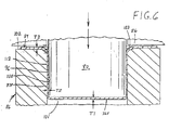
- punch 80 is aligned over female die 82.
- Metal strip 84 is disposed between punch 80 and female die 82.
- Stripper die 86 is disposed, about punch 80 so as to strip the work piece off of punch 80 as punch 80 is retracted from female die 82.
- metal strip 84 has a thickness "T3" of for example, about .15 mm.
- punch 80 has a side wall 92, and a bottom wall 94.
- Side wall 92 has an outer surface 96.
- female die 82 has a side wall 98 having an inner surface 100 facing cavity 101.
- a lip 103 is disposed between initializing land 102 and inner surface 100.
- Lip 103 includes an outer radius 104. and an inner radius 106 between outer radius 104 and inner surface 100.
- inner radius 106 is substantially smaller than outer radius 104.
- the ratio of the outer radius to the inner radius is about 2/1 to about 8/1.
- the radius is about 3//1 to about 6/1.
- the illustrated radius ratio is about 4/1.
- FIGURES 5-6 illustrates fabricating a cathode can for a size 312 (PR41) air depolarized button cell.
- the outer radius at lip 103 is about .75 mm to about 1.5 mm
- the inner radius is about -1 mm to about .5 mm.
- the diameter "D1" of the outer edge of the outer radius is about 8 mm to about 10 mm.
- the inside diameter "D2" of cavity 101. again for a PR41 cell, is about 7.68 mm to about 7.76 mm.
- the outside diameter "D3" of the outer surface of punch 80 is about .04 mm to about .055 mm. less than the diameter of the inner surface of the die.
- clearance "C1" between outer surface 96 of punch 80 and inner, surface 100 of cavity 101. which in FIGURE 6 corresponds to "T2.” is accordingly configured to be less than the thickness -T3- of metal strip 84 prior to working the metal strip.
- clearance "Cl” is typically about 65% to about 80%, preferably no more than about 85%, of the thickness of metal strip 84.
- clearance "Cl” between punch and die is about .04 mm to about .055 mm less than the unworked thickness of the metal strip.
- bottom wall 94 of the punch engages the top surface of the respective work piece element of metal strip 84. and pushes the work piece element into cavity 101 ahead of the bottom wall.
- the clearance between the outer surface of the punch and the inner surface of side wall 98 of the die is less than the thickness of the metal strip. Accordingly, as the metal strip is punched into the cavity, the metal strip is necessarily thinned.
- the mechanism for thinning the metal strip is set up by the utilization of the double radius lip 103 which defines the intersection of initializing land 102 and inner side wall 98.
- Applicants have discovered that a single small, or tight, radius as at 106 is satisfactory for creating a desired shape for the can, but risks tearing or cracking the metal being so formed: and that a single larger radius as at 108 forms without metal failure, but does not create the desired shape for the can.
- the double radius structure fabricates a satisfactory can shape while satisfactorily attenuating risk of metal failure during this first punch step 72.
- outer surface 112 of the metal strip is in sliding, frictional engagement against inner surface 100 of side wall 98.
- the outer surface of the metal strip material is cold-worked by the sliding of the outer surface of the metal strip along the interface of the metal strip with side wall 98 of die 82.
- the metal strip is under tension from the leading of bottom wall 94 of the punch, and is simultaneously under the compressive force of side walls 92 and 98 urging thinning of the metal strip in order to fit into the clearance between punch and die in cavity 101.
- outer surface 112 of the side wall precursor 37P is worked by side wall 98 of the die.
- Side wall 98 is, of course, highly polished in order to properly work metal strip 84 and to impart a desirable polished finish to the side wall.
- Typical finish on inner surface 98 is less than 2 ⁇ in (0.051 ⁇ m), whereas typical finish on metal strip 84 and bottom wall 36P of the can precursor, is greater 2 ⁇ in (0.051 ⁇ m) such as up to 5 or more ⁇ in. (0.13 ⁇ m)
- Such working of surface 112 accomplishes two results.
- the resulting surface finish R A of an exemplary side wall 37 is less than 2 ⁇ in (0.51 ⁇ m) preferably less than 1.5 ⁇ m (0.038 ⁇ m).
- the surface is such as to measure less than 1 microinch.
- the finish is so smooth as to make it difficult to detect any surface finish measurement on an instrument having a sensitivity to R A 0.1 ⁇ in (0-002 ⁇ m).
- the first punch step has transformed the flat disc-like work piece element into a cup or can having substantially, though not entirely the full height "HCS1" of the finished cathode can of the invention. Namely, the height of the can at the completion of the first punch stroke is within a few thousandths of an inch of the finished height "HCS1.”
- punch 80 is withdrawn, and the can precursor so formed is stripped from the punch by stripper die 86.
- the work piece then moves on to second punch step 74.
- the inner diameter of the cavity is larger than at the first step, and the outer diameter of the punch is smaller than punch 80 in the first step. Operation of the second punch tightens the radius of the metal about lip 103, and further forms a sharper corner at the joinder of the bottom wall and the side wall of the cathode can precursor
- ironing occurs only in combination with drawing.
- fabrication of substantially the full height of the cathode can is accomplished only in combination with steps wherein the punch moves toward the female die.
- the step which performs the ironing commences with or from the work piece element in a flat disc-like configuration.
- the hardness and formability of the metal strip represent compromises between the need to form the strip in making the cathode can and the need to crimp the distal edges of side wall 37 in closing the cell at final assembly, and the corresponding desire to obtain as much strength as possible from a minimum material thickness.
- a preferred metal strip includes a core layer of cold rolled steel, plated on opposing surfaces with layers of nickel, each of the layers being about 00165 mm to about 00.215 mm thick.
- the plated three-layer structure is preferably but not necessarily diffusion annealed such that the nickel layers are diffusion bonded to the core layer.
- the diffusion annealed three-layer strip is then temper rolled to specified thickness which, in the preferred embodiment herein is about .15 mm.
- Temper of the metal strip is adapted from the Special Temper designation suggested by supplied Thomas Steel Strip' Corporation. Warren. Ohio. USA, from whom such metal strip can be obtained.
- the preferred such metal strip is designated Temper "3 Special” by Thomas Steel Strip.
- a similarly desirable material is available from Hille & Muller, Dusseldorf, Germany, under the temper designation "LG,” Table 1 illustrates properties of a preferred metal strip having the preferred "3 Special' temper designation, as well as an alternative material having a "4" temper designation. Both temper "3 Special- and temper -4' are acceptable for forming cathode cans of the invention. Other temper designations may be acceptable, for example where the steel composition is correspondingly adjusted.
- composition of preferred steel layer 60 is AISI 1008. which is less than 0.1 percent by weight carbon.
- Other steels can be used so long as they satisfy the above noted formability and strength requirements.
- a significant advantage of the apparatus and processes disclosed herein is that the resulting cathode can has a relatively thicker bottom wall 36 and a relatively thinner side wall 37.
- bottom walls of cans made according to the invention are about .152 mm thick, with modest variation.
- the stretched and polished or ironed side walls 37 are about 0.105 mm thick, reflecting the dimension of the clearance between punch and die in the first punch step.
- the greater thickness of the bottom wall benefits the need for thickness to provide strength in the bottom wall, while the lesser thickness in the side wall provides adequate strength for two reasons.
- the side wall is subjected primarily to in-line stresses that travel along the direction of extension of the side wall.
- the side wall is strengthened, toughened, such as by hardening, by the working of the metal as the side wall is thinned.
- the absolute amount of space taken up by the side wall is reduced, whereby the grommet and anode cans can be specified with correspondingly larger inner diameters, with the result that the space occupied by the anode cavity is correspondingly enlarged.
- the enlargement of the anode cavity increases the capacity of the anode cavity to receive additional electroactive anode material, whereby the electrical watt-hour capacity of the cell is increased.
- a further advantage of the can forming system, and methods, of the invention is that the bottom corner of the cathode can is formed by a stretching process, rather than a purely punching, compressive process, whereby there is no tendency for the bottom corner of the can to bulge outwardly. Accordingly, no allowance need be made in the specification for bulging cans, whereby the specification range for cell diameter can be tightened, toward a larger average diameter, whereby the average diameters of the seal and anode can may be increased accordingly, thereby to increase the size of the anode cavity. As suggested earlier, increasing the size of the anode cavity increases the amount of electroactive anodic zinc which can be packed into the cell, resulting in an increase in the absolute amount of useful electricity which can be extracted from a cell of a given IEC standard size.
- Materials suitable for use as metal strip 84 include nickel plated steel.
- the steel layer can be for example, cold rolled steel, cold rolled mild steel, or stainless steel. Other steels may be used as desired, so long as they exhibit suitable strength in combination with suitable forming capabilities.
- the nickel can be plated or clad onto the steel core layer.
- the nickel layers are preferably generally pure nickel.
- alloys of nickel are also acceptable, such as INCONEL (INCO alloy of nickel, a non-magnetic alloy): pure nickel with minor alloying elements (NICKEL 200 and related family of NICKEL 200 alloys such as NICKEL 201, etc.), all available from Huntington Alloys, a division of INCO Huntington, West Virginia. USA
- Some noble metals can also find use as plating, cladding etc. including for example, and without limitation, gold, silver, platinum, palladium, and the like.
Applications Claiming Priority (2)
| Application Number | Priority Date | Filing Date | Title |
|---|---|---|---|
| US09/168,556 US6205831B1 (en) | 1998-10-08 | 1998-10-08 | Method for making a cathode can from metal strip |
| EP98309654A EP0993056B1 (de) | 1998-10-08 | 1998-11-25 | Elektrochemische Zellen, deren Komponenten und Verfahren zu ihrer Herstellung |
Related Parent Applications (1)
| Application Number | Title | Priority Date | Filing Date |
|---|---|---|---|
| EP98309654A Division EP0993056B1 (de) | 1998-10-08 | 1998-11-25 | Elektrochemische Zellen, deren Komponenten und Verfahren zu ihrer Herstellung |
Publications (1)
| Publication Number | Publication Date |
|---|---|
| EP1705730A2 true EP1705730A2 (de) | 2006-09-27 |
Family
ID=22611988
Family Applications (2)
| Application Number | Title | Priority Date | Filing Date |
|---|---|---|---|
| EP06011599A Withdrawn EP1705730A2 (de) | 1998-10-08 | 1998-11-25 | Elektrochemische Zellen, deren Komponenten und Verfahren zu ihrer Herstellung |
| EP98309654A Expired - Lifetime EP0993056B1 (de) | 1998-10-08 | 1998-11-25 | Elektrochemische Zellen, deren Komponenten und Verfahren zu ihrer Herstellung |
Family Applications After (1)
| Application Number | Title | Priority Date | Filing Date |
|---|---|---|---|
| EP98309654A Expired - Lifetime EP0993056B1 (de) | 1998-10-08 | 1998-11-25 | Elektrochemische Zellen, deren Komponenten und Verfahren zu ihrer Herstellung |
Country Status (3)
| Country | Link |
|---|---|
| US (2) | US6205831B1 (de) |
| EP (2) | EP1705730A2 (de) |
| DE (1) | DE69834812T2 (de) |
Cited By (2)
| Publication number | Priority date | Publication date | Assignee | Title |
|---|---|---|---|---|
| CN103378318A (zh) * | 2012-04-17 | 2013-10-30 | 株式会社杰士汤浅国际 | 装置箱体及装置箱体的制造方法 |
| CN109994661A (zh) * | 2019-05-05 | 2019-07-09 | 宁波光华电池有限公司 | 碱性锌锰电池及电池钢壳的生产工艺 |
Families Citing this family (21)
| Publication number | Priority date | Publication date | Assignee | Title |
|---|---|---|---|---|
| US6372381B1 (en) * | 1999-02-05 | 2002-04-16 | Rayovac Corporation | Duplex-coated cathode cans, and electrochemical cells made therewith |
| US20020187391A1 (en) * | 2001-06-11 | 2002-12-12 | Buckle Keith E. | Anode cans for electrochemical cells |
| US6730433B2 (en) * | 2002-01-16 | 2004-05-04 | The Gillette Company | Thin-wall anode can |
| EP1508120B1 (de) * | 2002-05-28 | 2014-08-06 | Casio Computer Co., Ltd. | Ausgabevorrichtung für zusammengesetzte bilder und ablieferungsvorrichtung für zusammengesetzte bilder |
| WO2005018020A2 (en) * | 2003-08-13 | 2005-02-24 | Hille & Müller GMBH | Plate for housing and/or lids for button cells and process for manufacturing such a plate |
| FR2866592B1 (fr) * | 2004-02-19 | 2007-06-08 | Usinor | Procede de fabrication d'une piece composite |
| TWI267236B (en) * | 2004-09-30 | 2006-11-21 | Top Yang Technology Entpr Co | Metal housing structure of electric connector and method for manufacturing the same |
| US20060159989A1 (en) * | 2005-01-19 | 2006-07-20 | Truelove & Maclean, Inc. | System and process for forming battery cans |
| JP3742422B1 (ja) * | 2005-03-17 | 2006-02-01 | 日立マクセル株式会社 | 扁平形電池 |
| JP5008306B2 (ja) * | 2006-01-05 | 2012-08-22 | 日新製鋼株式会社 | バックルベース部材のダボ出し加工方法 |
| US8499462B2 (en) | 2006-04-10 | 2013-08-06 | The Gillette Company | Cutting members for shaving razors |
| US8011104B2 (en) | 2006-04-10 | 2011-09-06 | The Gillette Company | Cutting members for shaving razors |
| DE102007018259A1 (de) * | 2007-04-13 | 2008-10-16 | Varta Microbattery Gmbh | Knopfzelle mit beschichteter Außenseite |
| DE102008018656B9 (de) * | 2008-04-11 | 2009-07-09 | Thyssenkrupp Steel Ag | Verfahren zur Herstellung von hochmaßhaltigen Halbschalen |
| JP2010069504A (ja) * | 2008-09-18 | 2010-04-02 | Sumitomo Electric Ind Ltd | プレス体 |
| US20100068614A1 (en) * | 2008-09-18 | 2010-03-18 | Koji Yamaguchi | Flat battery |
| DE102008037612B4 (de) * | 2008-11-28 | 2014-01-23 | Thyssenkrupp Steel Europe Ag | Verfahren und Werkzeugsatz zur Herstellung von flanschbehafteten, hoch maßhaltigen und tiefgezogenen Halbschalen |
| CN101869938A (zh) * | 2009-04-21 | 2010-10-27 | 鸿富锦精密工业(深圳)有限公司 | 加工设备及其加工方法,以及采用该加工方法制成的筒形件 |
| DE102009059197A1 (de) * | 2009-12-17 | 2011-06-22 | ThyssenKrupp Steel Europe AG, 47166 | Verfahren und Vorrichtung zur Herstellung eines Halbschalenteils |
| US10270142B2 (en) | 2011-11-07 | 2019-04-23 | Energizer Brands, Llc | Copper alloy metal strip for zinc air anode cans |
| JP5958565B2 (ja) * | 2015-01-14 | 2016-08-02 | Jfeスチール株式会社 | 打抜き加工方法、打抜き加工装置、および積層鉄心の製造方法 |
Family Cites Families (76)
| Publication number | Priority date | Publication date | Assignee | Title |
|---|---|---|---|---|
| DE497493C (de) * | 1926-06-22 | 1930-05-07 | Heraeus Vacuumschmelze Akt Ges | Liegende, mechanisch angetriebene Presse fuer hohen Druck |
| CH508283A (de) | 1969-05-09 | 1971-05-31 | Leclanche Sa | Alkalisches Element |
| AU456214B2 (en) | 1971-01-18 | 1974-12-12 | Timex Corporation | Primary cell case |
| US3746580A (en) | 1971-08-19 | 1973-07-17 | Esb Inc | Gas depolarizable galvanic cell |
| USRE31413E (en) | 1974-01-30 | 1983-10-11 | Gould Inc. | Gas depolarized electrochemical cells and method of assembly |
| US3897265A (en) | 1974-01-30 | 1975-07-29 | Gte Laboratories Inc | Electrochemical cells |
| DE2535269C3 (de) | 1975-08-07 | 1979-01-04 | Varta Batterie Ag, 3000 Hannover | Galvanisches Primärelement mit alkalischem Elektrolyten und einer hydrophoben Luftelektrode |
| US4041211A (en) | 1975-10-06 | 1977-08-09 | Unican Electrochemical Products Ltd. | Production of zinc-air button cell |
| FR2378363A1 (fr) | 1977-01-21 | 1978-08-18 | Accumulateurs Fixes | Generateurs electrochimiques de forme bouton |
| CH612542A5 (de) | 1977-02-26 | 1979-07-31 | Varta Batterie | |
| US4166157A (en) | 1977-07-11 | 1979-08-28 | Exxon Research & Engineering Co. | Double sealable button cell with corrosion resistant can and method |
| US4105830A (en) | 1977-08-01 | 1978-08-08 | Union Carbide Corporation | Air depolarized cell |
| JPS5481422U (de) | 1977-11-21 | 1979-06-09 | ||
| US4189526A (en) | 1978-05-05 | 1980-02-19 | Gould Inc. | Metal/oxygen cells and method for optimizing the active life properties thereof |
| CH639512A5 (de) | 1978-07-06 | 1983-11-15 | Leclanche Sa | Wasserarme alkalische primaerzelle mit langer lebensdauer. |
| JPS5840304B2 (ja) | 1978-07-10 | 1983-09-05 | 日立マクセル株式会社 | アルカリ電池 |
| JPS5512672A (en) | 1978-07-14 | 1980-01-29 | Toshiba Battery Co Ltd | Button type air cell |
| JPS5525916A (en) | 1978-08-11 | 1980-02-25 | Toshiba Battery Co Ltd | Button type air cell |
| JPS5856459B2 (ja) | 1978-12-11 | 1983-12-15 | 富士電気化学株式会社 | 偏平型密閉アルカリ電池 |
| DE2936781A1 (de) | 1979-09-12 | 1981-04-02 | Varta Batterie Ag, 3000 Hannover | Galvanisches element |
| JPS56126251A (en) | 1980-03-08 | 1981-10-03 | Ishizaki Press Kogyo Kk | Lid of battery jar and its preparing method |
| US4262062A (en) | 1980-03-24 | 1981-04-14 | Timex Corporation | Metal-air battery with environment control for intermittent high current demand |
| JPS56167265A (en) | 1980-05-26 | 1981-12-22 | Matsushita Electric Ind Co Ltd | Manufacture of battery sealing plate |
| DE3034600A1 (de) | 1980-09-13 | 1982-09-30 | Varta Batterie Ag, 3000 Hannover | Galvanische rund- oder knopfzelle |
| US4343869A (en) | 1981-02-09 | 1982-08-10 | Ray-O-Vac Corporation | Seal for metal-air batteries |
| US4369568A (en) | 1981-02-09 | 1983-01-25 | Ray-O-Vac Corporation | Method for manufacturing cells utilizing centrifuging techniques |
| CA1185318A (en) | 1981-10-26 | 1985-04-09 | Marian Wiacek | Assembly of air-depolarized cells |
| GB2110464A (en) | 1981-11-19 | 1983-06-15 | Metal Box Co Ltd | Electrically conductive component |
| US4404266A (en) | 1982-03-15 | 1983-09-13 | Union Carbide Corporation | Miniature air cells with seal |
| US4457990A (en) | 1982-03-19 | 1984-07-03 | Union Carbide Corporation | Thin miniature cell construction with reshaped gasket |
| EP0094272A1 (de) | 1982-05-12 | 1983-11-16 | Union Carbide Corporation | Zell-deckel für galvanische Zellen |
| US4507370A (en) | 1982-06-28 | 1985-03-26 | Union Carbide Corporation | Miniature galvanic cell construction providing gas channels between electrode compartments |
| JPS5914251A (ja) | 1982-07-14 | 1984-01-25 | Matsushita Electric Ind Co Ltd | 密閉式電池 |
| JPS5954170A (ja) | 1982-09-20 | 1984-03-28 | Matsushita Electric Ind Co Ltd | ボタン型電池用缶の製造法 |
| EP0118614B1 (de) | 1982-12-15 | 1987-09-09 | Hitachi Maxell Ltd. | Alkalische zelle |
| DE3314624A1 (de) | 1983-04-22 | 1984-10-25 | Varta Batterie Ag, 3000 Hannover | Luftsauerstoffzelle |
| DK8402964A (de) | 1983-06-23 | 1984-12-24 | ||
| US4591539A (en) | 1983-06-23 | 1986-05-27 | Rayovac Corporation | Metal-air cathode button cell |
| JPS6041752A (ja) | 1983-08-17 | 1985-03-05 | Matsushita Electric Ind Co Ltd | ボタン型空気電池 |
| JPS6075558A (ja) * | 1983-10-01 | 1985-04-27 | Daiwa Can Co Ltd | エキスパンド加工前のdi罐の熱処理法 |
| JPS60101858A (ja) | 1983-11-08 | 1985-06-05 | Matsushita Electric Ind Co Ltd | ボタン型アルカリ電池 |
| JPS60151957A (ja) | 1984-01-19 | 1985-08-10 | Matsushita Electric Ind Co Ltd | ボタン型アルカリ電池 |
| JPS612279A (ja) | 1984-06-14 | 1986-01-08 | Matsushita Electric Ind Co Ltd | 空気電池 |
| JPS6122563A (ja) | 1984-07-11 | 1986-01-31 | Matsushita Electric Ind Co Ltd | 密閉電池 |
| JPS6122564A (ja) | 1984-07-11 | 1986-01-31 | Matsushita Electric Ind Co Ltd | 密閉電池 |
| JPS6164063A (ja) | 1984-09-06 | 1986-04-02 | Toshiba Corp | 電池缶 |
| US5263354A (en) * | 1985-03-15 | 1993-11-23 | Saunders William T | Drawn can body methods, apparatus and products |
| JPH0665027B2 (ja) | 1985-07-08 | 1994-08-22 | 日立マクセル株式会社 | ボタン形電池の製造方法 |
| US4640874A (en) | 1985-07-29 | 1987-02-03 | Duracell Inc. | Metal/air cell |
| US4687714A (en) | 1986-02-04 | 1987-08-18 | Rayovac Corporation | Case for metal/air electrochemical cells, and cells and lantern batteries thereof |
| JPS6362170A (ja) | 1986-09-02 | 1988-03-18 | Matsushita Electric Ind Co Ltd | ボタン形空気電池 |
| US4791034A (en) | 1987-02-10 | 1988-12-13 | Rayovac Corporation | Sealing sleeve |
| JPS63294672A (ja) | 1987-05-27 | 1988-12-01 | Sony Corp | ボタン型空気亜鉛電池 |
| JPH01151150A (ja) * | 1987-12-08 | 1989-06-13 | Matsushita Electric Ind Co Ltd | 電池用正極缶の製造法 |
| JPH01154454A (ja) | 1987-12-09 | 1989-06-16 | Matsushita Electric Ind Co Ltd | ボタン形アルカリ電池 |
| ES2043917T3 (es) * | 1988-03-12 | 1994-01-01 | Karl Hehl | Herramienta de embutir para transformar chapas. |
| JPH02236949A (ja) | 1989-03-10 | 1990-09-19 | Matsushita Electric Ind Co Ltd | 空気ボタン電池 |
| JPH03297074A (ja) | 1990-04-17 | 1991-12-27 | Matsushita Electric Ind Co Ltd | 空気電池 |
| JPH04206443A (ja) | 1990-11-30 | 1992-07-28 | Matsushita Electric Ind Co Ltd | 空気電池 |
| JP2524001B2 (ja) | 1991-02-26 | 1996-08-14 | 松下電器産業株式会社 | 電池表面へのマ―キング方法 |
| JPH0529025A (ja) | 1991-07-17 | 1993-02-05 | Matsushita Electric Ind Co Ltd | ボタン形空気電池 |
| EP0617847A4 (en) | 1991-12-16 | 1996-01-24 | Matsi Inc | Collapsing foam anode backing for zinc-air battery. |
| US5279905A (en) | 1992-03-09 | 1994-01-18 | Eveready Battery Company, Inc. | Miniature zinc-air cell having an indium plated anode cupe |
| US5308711A (en) | 1993-02-09 | 1994-05-03 | Rayovac Corporation | Metal-air cathode and cell having catalytically active manganese compounds of valence state +2 |
| ES2106376T3 (es) | 1993-06-04 | 1997-11-01 | Katayama Tokushu Kogyo Kk | Vaso de baterias; chapa para formar un vaso de baterias y metodo para fabricar dicha chapa. |
| CA2100391A1 (en) | 1993-07-13 | 1995-01-14 | John Bamforth | Method for crimp closure of coin cell batteries |
| AU7925994A (en) | 1993-10-04 | 1995-05-01 | Eveready Battery Company Inc. | Process for ultrasonic sealing an anode cup into a gasket for electrochemical cells |
| EP0664169B1 (de) * | 1993-12-22 | 1999-03-10 | TOYO KOHAN Co., Ltd | Verfahren zum Formen eines metallischen Behalters |
| TW252961B (en) * | 1994-02-15 | 1995-08-01 | Toyo Seikan Kaisha Ltd | Method of producing seamless cans |
| JPH08173775A (ja) | 1994-10-24 | 1996-07-09 | Sumitomo Electric Ind Ltd | 酸素選択透過膜およびそれを用いた電池 |
| JPH08190901A (ja) | 1995-01-10 | 1996-07-23 | Hitachi Maxell Ltd | ボタン形アルカリ電池 |
| EP0732758A1 (de) * | 1995-03-15 | 1996-09-18 | Matsushita Electric Industrial Co., Ltd. | Verfahren zur Herstellung von Batteriebehältern |
| US5567538A (en) * | 1995-05-05 | 1996-10-22 | Rayovac Corporation | Metal-air cell having thin-walled anode and cathode cans |
| US5582932A (en) | 1995-05-05 | 1996-12-10 | Rayovac Corporation | Tempered thin-walled cathode can |
| US5591541A (en) | 1995-05-05 | 1997-01-07 | Rayovac Corporation | High steel content thin walled anode can |
| US6270921B1 (en) * | 2000-01-19 | 2001-08-07 | The Gillette Company | Air recovery battery |
-
1998
- 1998-10-08 US US09/168,556 patent/US6205831B1/en not_active Expired - Fee Related
- 1998-11-25 EP EP06011599A patent/EP1705730A2/de not_active Withdrawn
- 1998-11-25 DE DE69834812T patent/DE69834812T2/de not_active Expired - Fee Related
- 1998-11-25 EP EP98309654A patent/EP0993056B1/de not_active Expired - Lifetime
-
2001
- 2001-01-12 US US09/758,976 patent/US6569563B2/en not_active Expired - Lifetime
Cited By (2)
| Publication number | Priority date | Publication date | Assignee | Title |
|---|---|---|---|---|
| CN103378318A (zh) * | 2012-04-17 | 2013-10-30 | 株式会社杰士汤浅国际 | 装置箱体及装置箱体的制造方法 |
| CN109994661A (zh) * | 2019-05-05 | 2019-07-09 | 宁波光华电池有限公司 | 碱性锌锰电池及电池钢壳的生产工艺 |
Also Published As
| Publication number | Publication date |
|---|---|
| US6205831B1 (en) | 2001-03-27 |
| US20010001369A1 (en) | 2001-05-24 |
| DE69834812D1 (de) | 2006-07-20 |
| EP0993056A1 (de) | 2000-04-12 |
| US6569563B2 (en) | 2003-05-27 |
| DE69834812T2 (de) | 2006-11-23 |
| EP0993056B1 (de) | 2006-06-07 |
Similar Documents
| Publication | Publication Date | Title |
|---|---|---|
| EP0993056B1 (de) | Elektrochemische Zellen, deren Komponenten und Verfahren zu ihrer Herstellung | |
| US5658356A (en) | Metal-air cathode can having reduced corner radius and electrochemical cells made therewith | |
| US5591541A (en) | High steel content thin walled anode can | |
| US5567538A (en) | Metal-air cell having thin-walled anode and cathode cans | |
| US5582930A (en) | High energy density metal-air cell | |
| JP4491208B2 (ja) | 電池缶およびその製造方法ならびに電池 | |
| US6333124B1 (en) | Metal outer can for a battery and method of manufacturing same | |
| WO2006078690A2 (en) | System and process for forming battery cans | |
| CN101013747A (zh) | 硬币形电池 | |
| US5582932A (en) | Tempered thin-walled cathode can | |
| JP2003507861A (ja) | 金属−空気電池 | |
| CN100578841C (zh) | 薄壁阳极包壳 | |
| US6372381B1 (en) | Duplex-coated cathode cans, and electrochemical cells made therewith | |
| JPH1083800A (ja) | 電池缶とこの缶を用いた乾電池の製造方法 | |
| GB2347011A (en) | Zinc based electrochemical cell | |
| JP2946199B2 (ja) | ボタン形アルカリ電池およびその製造方法 | |
| KR20050037577A (ko) | 전지 케이스용 표면처리 강판 및 이를 사용한 전지 케이스 | |
| EP0991133A1 (de) | Elektrochemische Zellen und ihre Komponenten | |
| JPS60151957A (ja) | ボタン型アルカリ電池 | |
| JP2000011968A (ja) | ボタン形アルカリ電池 |
Legal Events
| Date | Code | Title | Description |
|---|---|---|---|
| PUAI | Public reference made under article 153(3) epc to a published international application that has entered the european phase |
Free format text: ORIGINAL CODE: 0009012 |
|
| AC | Divisional application: reference to earlier application |
Ref document number: 0993056 Country of ref document: EP Kind code of ref document: P |
|
| AK | Designated contracting states |
Kind code of ref document: A2 Designated state(s): DE FR GB |
|
| STAA | Information on the status of an ep patent application or granted ep patent |
Free format text: STATUS: THE APPLICATION HAS BEEN WITHDRAWN |
|
| 18W | Application withdrawn |
Effective date: 20070607 |